EP1715314B1 - Vorrichtung zur Detektion von Infrarotstrahlung, Lenksystem ausgestattet mit dieser Vorrichtung und selbstgesteuertes Geschoss ausgestattet mit diesem Lenksystem. - Google Patents
Vorrichtung zur Detektion von Infrarotstrahlung, Lenksystem ausgestattet mit dieser Vorrichtung und selbstgesteuertes Geschoss ausgestattet mit diesem Lenksystem. Download PDFInfo
- Publication number
- EP1715314B1 EP1715314B1 EP06290662A EP06290662A EP1715314B1 EP 1715314 B1 EP1715314 B1 EP 1715314B1 EP 06290662 A EP06290662 A EP 06290662A EP 06290662 A EP06290662 A EP 06290662A EP 1715314 B1 EP1715314 B1 EP 1715314B1
- Authority
- EP
- European Patent Office
- Prior art keywords
- casing
- titanium
- main body
- cold finger
- joined
- Prior art date
- Legal status (The legal status is an assumption and is not a legal conclusion. Google has not performed a legal analysis and makes no representation as to the accuracy of the status listed.)
- Expired - Lifetime
Links
Images

Classifications
-
- G—PHYSICS
- G01—MEASURING; TESTING
- G01J—MEASUREMENT OF INTENSITY, VELOCITY, SPECTRAL CONTENT, POLARISATION, PHASE OR PULSE CHARACTERISTICS OF INFRARED, VISIBLE OR ULTRAVIOLET LIGHT; COLORIMETRY; RADIATION PYROMETRY
- G01J5/00—Radiation pyrometry, e.g. infrared or optical thermometry
- G01J5/02—Constructional details
- G01J5/04—Casings
-
- G—PHYSICS
- G01—MEASURING; TESTING
- G01J—MEASUREMENT OF INTENSITY, VELOCITY, SPECTRAL CONTENT, POLARISATION, PHASE OR PULSE CHARACTERISTICS OF INFRARED, VISIBLE OR ULTRAVIOLET LIGHT; COLORIMETRY; RADIATION PYROMETRY
- G01J5/00—Radiation pyrometry, e.g. infrared or optical thermometry
- G01J5/02—Constructional details
- G01J5/06—Arrangements for eliminating effects of disturbing radiation; Arrangements for compensating changes in sensitivity
- G01J5/061—Arrangements for eliminating effects of disturbing radiation; Arrangements for compensating changes in sensitivity by controlling the temperature of the apparatus or parts thereof, e.g. using cooling means or thermostats
Definitions
- the invention relates to devices for detecting electromagnetic radiation, intended in particular to equip the homing devices of self-guided projectiles (missiles, rockets, etc.).
- FPA electromagnetic radiation sensor
- the cooling of the sensor mounted in a housing provided with a window transparent to the electromagnetic radiation for the transmission thereof to the sensor, is commonly provided by a heat exchanger housed in a cold finger fixed to the housing and a wall forming a support for the sensor.
- the detected radiation is generally infrared.
- the material used for the transmission window is selected from germanium, sapphire or silica.
- the housing must be perfectly sealed to maintain the vacuum in the enclosure. This sealing must be ensured not only at the junction of the various constituent parts of the housing, but also, on the one hand, at the junction of these parts with the transmission window, and on the other hand at the level of the passage of electrical connectors passing through the housing. housing and connecting the sensor to an external electronic card processing data transmitted by it (also called "proximity card").
- the housing must be structurally rigid to minimize measurement errors.
- the material in which is realized the housing must have a relatively low coefficient of thermal expansion with regard to the large temperature differences to which the appliance is subjected (from -40 ° C to + 80 ° C)
- the camera case was made of blown glass.
- the sensor connections were simply stuck in the still soft glass, and the transmission window simply sealed on the housing.
- the Kovar is entirely satisfactory with regard to the specifications mentioned above.
- the technique of sending (that is to say glass sealing) connections on Kovar is now relatively well controlled.
- Other techniques for sealing connections have also been proposed (see, for example, the patent application French FR 2 717 981 ).
- an electromagnetic wave detection apparatus for this purpose, they propose, in a first aspect, an electromagnetic wave detection apparatus, according to the features of claim 1.
- the cold finger comprises a base, from which the Dewar container protrudes, and through which the cold finger is fixed to the housing.
- fixing the cold finger to the housing is performed by laser welding.
- the sealed passages in the main body are sealed with glass to the main body.
- the window it is preferably made of germanium, but it can also be made of sapphire or silica. In addition, it is preferably attached to the opening of the bonnet by solder, for example by using a lead / indium alloy.
- the material in which the housing and the cold finger are made is for example a titanium alloy TA6V, or a titanium TA40.
- the inventors also propose, in a second aspect, a homing device equipped with such a device, as well as a self-guided projectile equipped with such a homing device.
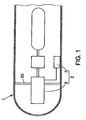
- a projectile 1 in this case a missile
- an optical homing 2 comprising a data processing unit 3 from an infrared sensor 4, and a device 5 of detection of electromagnetic radiation (in this case infrared radiation) in which this sensor 4 is mounted.
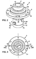
- the apparatus 5 represented in particular on figure 2 to 5 , comprises a hollow housing 6 defining an enclosure 7 in which there is a partial vacuum (10 -6 mbar approximately). This vacuum is achieved by pumping via a pipe 8 permanently fixed on the housing 6 through a hole 9 formed therein, and an outer end 10 is crushed and sealed at the end of the pumping.
- the housing 6 has a window 11 made of a material transmitting the electromagnetic radiation to which the sensor is sensitive (for the infrared, germanium, sapphire or silica will preferably be chosen).
- the apparatus further comprises a cold finger 12 comprising a base 13 sealingly attached to the housing 6, and a Dewar container 14 in the form of a hollow tube which extends axially (i.e. say perpendicular to the window) in the chamber from the base 13.
- the Dewar container 14 opens, at an upstream end, through an opening 15 and is closed, at a downstream end, by an end wall 16 having an outer face 17, located at the right of the window 11 and turned towards it.
- the infrared sensor 4 is mounted on the end wall 16 of the Dewar container 14, on the side of its outer face 17, so that it can be struck by the infrared radiation passing through the window 11.
- the sensor 4 is electrically connected to a circuit board integrated (called proximity card, not shown), mounted outside the housing 6, through connectors 18 passing through the housing 6 by sealed passages 19 lined with glass.
- each group of connectors is connected to the sensor 4 by a flexible line 20 on which electrical tracks (not visible) are screen printed for the connection of the sensor 4 to each connector 18.
- the sensor 4 can only operate at extremely low temperatures, of the order of 77 to 100 ° K.
- the apparatus 5 comprises a tubular heat exchanger (not shown) housed in the Dewar container 14, and cooling the sensor 4 by Joule Thomson effect.
- the vacuum prevailing in the enclosure aims to prevent the formation of condensation, especially on the sensor 4 and on the window 11, which would affect the transmission of radiation.
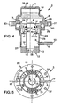
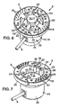
- the apparatus 5 is provided, as is visible on 4, 6 and 7, getters 21 electrically connected to the proximity card by the Intermediate connectors 22 bent through the housing 6 through sealed passages 23 also filled with glass.
- the housing 6 and the cold finger 12 are both made of titanium, for example a titanium TA40, called “pure”, or in a titanium alloy, such as a TAV6 alloy, that is to say an alloy of titanium, aluminum (whose mass percentage is between 5.5 and 6.75) and vanadium (whose mass percentage is between 3, 5 and 4.5).
- a titanium TA40 called “pure”
- a titanium alloy such as a TAV6 alloy, that is to say an alloy of titanium, aluminum (whose mass percentage is between 5.5 and 6.75) and vanadium (whose mass percentage is between 3, 5 and 4.5).
- titanium has better machinability than Kovar in particular. As a result, compared with the infrared detection apparatus made in this material, a reduction in the number of parts, to the benefit of the simplicity of the structure and assembly of the device 5.
- Fixing the flange 29 to the main body 24 and the cover 34 to the flange 29 is performed by interlocking and laser welding at the interfaces. This type of welding, combined with the material of the parts 24, 29, 34, ensures a perfect seal of the enclosure 7 (the seal being measured with helium, the leakage rate being less than 10 -10 Atm / cm 3 / s).
- the cold finger 12 consists of two parts made of the same material as the housing 6, namely, on the one hand, the base 13, which is in the form of a cylinder pierced with a bore 36, laser-welded, along an upper peripheral edge 37, to the main body 24 of the housing 6, and, secondly, the Dewar container 14, which is fitted into the bore 36 of the base 13 by being laser welded to it.
- the queusot 8 is made of copper or a copper-based alloy. It passes through the housing 6 through the hole 9; it is fixed to the casing 6 by brazing on an outer edge of the hole 9.
- the connectors 18, 22, made of a nickel-plated iron / nickel alloy, are fixed to the main body 24 of the housing 6 by means of spraying, that is to say by sealing, in the holes, glass sleeves 38, 39 enclosing the connectors 18, 22 to thereby form the sealed passages 19, 23.
- Each getter 21 comprises a cylindrical body 40 made of an absorbent alloy (it is for example an alloy of iron, zirconia and vanadium) fitted on a metal pin 41 of molybdenum, welded to an upper end 42 to the connector 22 and fixed at a lower end 43 to the housing 6 by means of an arc welding.
- Each getter 21 is activated by circulation in its pin 41 of a low intensity electric current from the proximity card.
- the window 11 is in turn fixed to the housing 6 (more precisely on an edge 44 of the opening 35 formed in the cover 34) by means of a lead / indium solder under a hydrogenated argon atmosphere at a temperature of 250 ° C. About C, after local metallization of chromium titanium or gold. It should be noted that this technique is particularly suitable when the window 11 is germanium, its attachment to the housing 6 being both solid and waterproof.
- the materials of the cold finger 12 and of the casing 6 are identical, they also have identical thermal expansion coefficients, so that, on the one hand, the temperature variations do not cause any stress at the level of the laser welds. the seal is thus permanently ensured (it should be noted that the life expectancy of the missile is 25 years, which takes into account the duration of its storage) and, on the other hand, the positioning of the cold finger 12 is both precise and stable.
- titanium has excellent corrosion resistance, particularly with respect to Kovar. This aspect is important when the apparatus 5 is immersed in an unsealed environment.
Landscapes
- Physics & Mathematics (AREA)
- General Physics & Mathematics (AREA)
- Spectroscopy & Molecular Physics (AREA)
- Photometry And Measurement Of Optical Pulse Characteristics (AREA)
- Aiming, Guidance, Guns With A Light Source, Armor, Camouflage, And Targets (AREA)
- Geophysics And Detection Of Objects (AREA)
Claims (10)
- Gerät (5) zur Detektion von elektromagnetischen Wellen, das umfasst:- ein Gehäuse (6), das einen Vakuumraum (7) definiert und durch Montage von mehreren Stücken gebildet ist, von denen drei (24, 29, 34) aus Titan oder aus einer Titanlegierung bestehen, wobei zwei von ihnen (29, 34) durch Laserschweißen aneinander befestigt sind, und- einen kalten Finger (12) mit einem röhrenförmigen Dewar-Gefäß (14) aus Titan oder einer Titanlegierung, das sich in den Raum (7) erstreckt, während er dicht am Gehäuse (6) auf der Höhe eines Endes des Dewar-Gefäßes (14) befestigt ist, dessen anderes Ende durch eine Endwand (16) verschlossen ist, an der ein Sensor (4) für elektromagnetische Wellen angebracht ist;wobei die zwei Stücke (29, 34) des Gehäuses (6), die aneinander (29, 34) befestigt sind, folgende sind:- ein Flansch (29) zur Befestigung des Geräts (5) an einem Träger (30) außerhalb des Gehäuses (6); und- eine Haube (34), die mit einer Öffnung (35) versehen ist, die direkt über dem Sensor (4) liegt und dicht mit einem Fenster (11) verschlossen ist, das für die elektromagnetische Strahlung durchlässig ist, für die der Sensor (4) empfindlich ist;wobei dieses Gerät (5) dadurch gekennzeichnet ist, dass das dritte der drei Stücke (24, 29, 34) aus Titan oder einer Titanlegierung, die zusammengefügt sind, um das Gehäuse (6) zu bilden, ein Hauptkörper (24) ist, der mit dichten Durchgängen (19, 23) für Verbindungselemente (18, 22) zur Verbindung des Sensors (4) mit einer elektronischen Karte außerhalb des Gehäuses (6) ausgestattet ist;
dass der Flansch (29) am einen und anderen der zwei anderen Stücke (24, 34) aus Titan oder einer Titanlegierung des Gehäuses (6) durch Laserschweißen befestigt ist, und die Endwand (16) des kalten Fingers (12) auch aus Titan oder einer Titanlegierung besteht, so dass der kalte Finger (12) und das Gehäuse (6) alle beide aus Titan oder einer Titanlegierung hergestellt sind, wobei die Materialien des kalten Fingers (12) und des Gehäuses (6) identisch sind,
und dass der kalte Finger (12) außerdem einen Sockel (13) umfasst, der auch aus Titan oder einer Titanlegierung, vorzugsweise aus demselben Material wie das Gehäuse (6) und/oder das Dewar-Gefäß (14) besteht, und in Form eines Zylinders vorliegt, der mit einer zentralen Bohrung (36) durchbohrt ist und dicht durch Laserschweißen einerseits am Hauptkörper (24) des Gehäuses (6), entlang eines Umfangsrandes (37) des Sockels (13) und andererseits am Dewar-Gefäß (14), das in die Bohrung (36) des Sockels (13) eingefügt ist, befestigt ist, so dass das Dewar-Gefäß (14) sich vorstehend vom Sockel (13) erstreckt. - Gerät (5) nach Anspruch 1, dadurch gekennzeichnet, dass:- der Hauptkörper (24) einen röhrenförmigen Abschnitt (25), der das Dewar-Gefäß (14) umgibt, und einen Kranz (26) aus einem Stück mit dem röhrenförmigen Abschnitt (25) umfasst, in den Löcher (27, 28) für die dichten Durchgänge (19, 23) der Verbindungselemente (18, 22) gebohrt sind; und/oder- der Befestigungsflansch (29) einen Kranz (31) umfasst, in den Befestigungslöcher (32) und eine Rille (33) zur Positionierung gebohrt sind, die mit einem Stück zusammenwirken kann, das vorstehend am äußeren Träger (30) vorgesehen ist.
- Gerät (5) nach einem der Ansprüche 1 oder 2, dadurch gekennzeichnet, dass die dichten Durchgänge (19, 23) im Hauptkörper (24) mit Glas (38, 39), das auf den Hauptkörper (24) aufgesiegelt ist, oder mit Keramikplättchen, die an den Hauptkörper (24) hartgelötet sind und die Verbindungselemente (18, 22) einspannen, verkleidet sind.
- Gerät (5) nach einem der Ansprüche 1 bis 3, dadurch gekennzeichnet, dass die Befestigung des Flanschs (29) am Hauptkörper (24) und der Haube (34) am Flansch (29) durch Einfügen und Laserschweißen auf der Höhe der Grenzflächen durchgeführt ist.
- Gerät (5) nach einem der Ansprüche 1 bis 4, dadurch gekennzeichnet, dass das Fenster (11) in der Öffnung (35) der Haube (34) durch Hartlöten befestigt ist, das eine Blei/Indium-Legierung einsetzt.
- Gerät (5) nach einem der Ansprüche 1 bis 5, dadurch gekennzeichnet, dass das Fenster (11) aus Germanium, Saphir oder Siliziumdioxid hergestellt ist.
- Gerät (5) nach einem der Ansprüche 1 bis 6, dadurch gekennzeichnet, dass das Gehäuse (6) und der kalte Finger (12) aus einer Titanlegierung TA6V hergestellt sind.
- Gerät (5) nach einem der Ansprüche 1 bis 7, dadurch gekennzeichnet, dass das Gehäuse (6) und der kalte Finger (12) aus Titan TA40 hergestellt sind.
- Zielsuchkopf (2), der mit einem Gerät (5) nach einem der Ansprüche 1 bis 8 ausgestattet ist.
- Selbstgesteuertes Projektil (1) mit einem Zielsuchkopf (2), der mit einem Gerät (5) nach einem der Ansprüche 1 bis 8 ausgestattet ist.
Applications Claiming Priority (1)
| Application Number | Priority Date | Filing Date | Title |
|---|---|---|---|
| FR0504097A FR2884915A1 (fr) | 2005-04-22 | 2005-04-22 | Appareil de detection de rayonnement infrarouge, autodirecteurequipe d'un tel appareil et projectile autoguide equipe d'un tel autodirecteur. |
Publications (2)
| Publication Number | Publication Date |
|---|---|
| EP1715314A1 EP1715314A1 (de) | 2006-10-25 |
| EP1715314B1 true EP1715314B1 (de) | 2011-09-28 |
Family
ID=35447952
Family Applications (1)
| Application Number | Title | Priority Date | Filing Date |
|---|---|---|---|
| EP06290662A Expired - Lifetime EP1715314B1 (de) | 2005-04-22 | 2006-04-21 | Vorrichtung zur Detektion von Infrarotstrahlung, Lenksystem ausgestattet mit dieser Vorrichtung und selbstgesteuertes Geschoss ausgestattet mit diesem Lenksystem. |
Country Status (5)
| Country | Link |
|---|---|
| EP (1) | EP1715314B1 (de) |
| AT (1) | ATE526564T1 (de) |
| ES (1) | ES2372613T3 (de) |
| FR (1) | FR2884915A1 (de) |
| IL (1) | IL175060A (de) |
Cited By (1)
| Publication number | Priority date | Publication date | Assignee | Title |
|---|---|---|---|---|
| CN103575404A (zh) * | 2013-11-05 | 2014-02-12 | 国家电网公司 | 一种用于gis的可拆装内置式红外测温装置 |
Families Citing this family (1)
| Publication number | Priority date | Publication date | Assignee | Title |
|---|---|---|---|---|
| CN107340061B (zh) * | 2017-05-31 | 2020-01-24 | 中国电子科技集团公司第十一研究所 | 一种红外探测器冷箱 |
Family Cites Families (5)
| Publication number | Priority date | Publication date | Assignee | Title |
|---|---|---|---|---|
| US4954708A (en) * | 1989-08-23 | 1990-09-04 | Santa Barbara Research Center | Low distortion focal plane platform |
| US5187939A (en) * | 1991-06-03 | 1993-02-23 | Hughes Aircraft Company | Rapid cooldown dewar |
| US5198671A (en) * | 1991-06-17 | 1993-03-30 | Rockwell International Corporation | Apparatus for large area infrared focal plane |
| US5598966A (en) * | 1994-07-19 | 1997-02-04 | Santa Barbara Research Center | Brazed lower vacuum housing for a dewar |
| US6070414A (en) * | 1998-04-03 | 2000-06-06 | Raytheon Company | Cryogenic cooler with mechanically-flexible thermal interface |
-
2005
- 2005-04-22 FR FR0504097A patent/FR2884915A1/fr not_active Withdrawn
-
2006
- 2006-04-20 IL IL175060A patent/IL175060A/en active IP Right Grant
- 2006-04-21 ES ES06290662T patent/ES2372613T3/es not_active Expired - Lifetime
- 2006-04-21 AT AT06290662T patent/ATE526564T1/de not_active IP Right Cessation
- 2006-04-21 EP EP06290662A patent/EP1715314B1/de not_active Expired - Lifetime
Cited By (2)
| Publication number | Priority date | Publication date | Assignee | Title |
|---|---|---|---|---|
| CN103575404A (zh) * | 2013-11-05 | 2014-02-12 | 国家电网公司 | 一种用于gis的可拆装内置式红外测温装置 |
| CN103575404B (zh) * | 2013-11-05 | 2016-01-20 | 国家电网公司 | 一种用于gis的可拆装内置式红外测温装置 |
Also Published As
| Publication number | Publication date |
|---|---|
| ES2372613T3 (es) | 2012-01-24 |
| EP1715314A1 (de) | 2006-10-25 |
| ATE526564T1 (de) | 2011-10-15 |
| IL175060A0 (en) | 2006-08-20 |
| FR2884915A1 (fr) | 2006-10-27 |
| IL175060A (en) | 2010-12-30 |
Similar Documents
| Publication | Publication Date | Title |
|---|---|---|
| EP1139358B1 (de) | Elektrisches Schaltgerät mit einer Vakuumröhre und eine flexible elektrische Verbindung | |
| CN104159423B (zh) | 气密性密封的光电或电光部件及其生产方法 | |
| EP0488863A1 (de) | Pyrotechnischer Detonator mit Koaxialverbindungen | |
| FR2711014A1 (fr) | Lampe à quartz à deux extrémités et procédé de fabrication de cette lampe. | |
| FR2784183A1 (fr) | Palpeur de temperature | |
| EP0229549A1 (de) | Hermetischer Koaxialsteckverbinder | |
| FR2772983A1 (fr) | Dispositif a ampoule a decharge electrique | |
| EP1715314B1 (de) | Vorrichtung zur Detektion von Infrarotstrahlung, Lenksystem ausgestattet mit dieser Vorrichtung und selbstgesteuertes Geschoss ausgestattet mit diesem Lenksystem. | |
| FR2633465A1 (fr) | Oscillateur ultrastable fonctionnant a pression atmospherique et sous vide | |
| EP1067356A1 (de) | Optischer Zünder mit einem Gradientenindex-Glasstab | |
| EP0004220B1 (de) | Sonnenenergiekollektor | |
| EP0526315B1 (de) | Pyrotechnisch getriebener elektrischer Schalter | |
| FR2539249A1 (fr) | Boitier a dissipation thermique elevee notamment pour microelectronique | |
| EP2751822A1 (de) | Anordnung für langfristige stromspeicherung mit einem zwischenverbindungsteil | |
| FR2813662A1 (fr) | Evaporateur capillaire pour boucle de transfert | |
| EP3052909A1 (de) | Flexible bestückte leiterplatte mit geringer emissivität | |
| FR3133949A1 (fr) | Connecteur électrique | |
| FR2710982A1 (fr) | Source de lumière thermique dans un boîtier métallique. | |
| EP4291862B1 (de) | System zur detektion elektromagnetischer strahlung und kühlverfahren | |
| FR2721380A1 (fr) | Four électrique de cuisson. | |
| FR2587797A1 (fr) | Dispositif de retenue pour un getter amorce electriquement, gyroscope a laser contenant un tel dispositif et procede de retenue d'un getter dans un tel gyroscope a laser | |
| FR2512272A1 (fr) | Lampe a vapeur de metal alcalin haute pression | |
| WO2009083534A1 (fr) | Refroidissement d'un tube générateur de rayons x | |
| US9233430B2 (en) | Mounted optical component, method for the production thereof and use of same | |
| EP0237801A1 (de) | Laser mit mindestens einer Abdichtung |
Legal Events
| Date | Code | Title | Description |
|---|---|---|---|
| PUAI | Public reference made under article 153(3) epc to a published international application that has entered the european phase |
Free format text: ORIGINAL CODE: 0009012 |
|
| AK | Designated contracting states |
Kind code of ref document: A1 Designated state(s): AT BE BG CH CY CZ DE DK EE ES FI FR GB GR HU IE IS IT LI LT LU LV MC NL PL PT RO SE SI SK TR |
|
| AX | Request for extension of the european patent |
Extension state: AL BA HR MK YU |
|
| 17P | Request for examination filed |
Effective date: 20070223 |
|
| 17Q | First examination report despatched |
Effective date: 20070321 |
|
| AKX | Designation fees paid |
Designated state(s): AT BE BG CH CY CZ DE DK EE ES FI FR GB GR HU IE IS IT LI LT LU LV MC NL PL PT RO SE SI SK TR |
|
| GRAP | Despatch of communication of intention to grant a patent |
Free format text: ORIGINAL CODE: EPIDOSNIGR1 |
|
| RIN1 | Information on inventor provided before grant (corrected) |
Inventor name: ROSELLO, JEROME Inventor name: COURSAGET, FRANCOIS |
|
| GRAS | Grant fee paid |
Free format text: ORIGINAL CODE: EPIDOSNIGR3 |
|
| GRAA | (expected) grant |
Free format text: ORIGINAL CODE: 0009210 |
|
| AK | Designated contracting states |
Kind code of ref document: B1 Designated state(s): AT BE BG CH CY CZ DE DK EE ES FI FR GB GR HU IE IS IT LI LT LU LV MC NL PL PT RO SE SI SK TR |
|
| REG | Reference to a national code |
Ref country code: GB Ref legal event code: FG4D Free format text: NOT ENGLISH |
|
| REG | Reference to a national code |
Ref country code: CH Ref legal event code: EP |
|
| REG | Reference to a national code |
Ref country code: IE Ref legal event code: FG4D |
|
| REG | Reference to a national code |
Ref country code: NL Ref legal event code: T3 |
|
| REG | Reference to a national code |
Ref country code: DE Ref legal event code: R096 Ref document number: 602006024670 Country of ref document: DE Effective date: 20111208 |
|
| REG | Reference to a national code |
Ref country code: ES Ref legal event code: FG2A Ref document number: 2372613 Country of ref document: ES Kind code of ref document: T3 Effective date: 20120124 |
|
| PG25 | Lapsed in a contracting state [announced via postgrant information from national office to epo] |
Ref country code: LT Free format text: LAPSE BECAUSE OF FAILURE TO SUBMIT A TRANSLATION OF THE DESCRIPTION OR TO PAY THE FEE WITHIN THE PRESCRIBED TIME-LIMIT Effective date: 20110928 Ref country code: FI Free format text: LAPSE BECAUSE OF FAILURE TO SUBMIT A TRANSLATION OF THE DESCRIPTION OR TO PAY THE FEE WITHIN THE PRESCRIBED TIME-LIMIT Effective date: 20110928 Ref country code: SE Free format text: LAPSE BECAUSE OF FAILURE TO SUBMIT A TRANSLATION OF THE DESCRIPTION OR TO PAY THE FEE WITHIN THE PRESCRIBED TIME-LIMIT Effective date: 20110928 |
|
| LTIE | Lt: invalidation of european patent or patent extension |
Effective date: 20110928 |
|
| PG25 | Lapsed in a contracting state [announced via postgrant information from national office to epo] |
Ref country code: GR Free format text: LAPSE BECAUSE OF FAILURE TO SUBMIT A TRANSLATION OF THE DESCRIPTION OR TO PAY THE FEE WITHIN THE PRESCRIBED TIME-LIMIT Effective date: 20111229 Ref country code: SI Free format text: LAPSE BECAUSE OF FAILURE TO SUBMIT A TRANSLATION OF THE DESCRIPTION OR TO PAY THE FEE WITHIN THE PRESCRIBED TIME-LIMIT Effective date: 20110928 Ref country code: CY Free format text: LAPSE BECAUSE OF FAILURE TO SUBMIT A TRANSLATION OF THE DESCRIPTION OR TO PAY THE FEE WITHIN THE PRESCRIBED TIME-LIMIT Effective date: 20110928 Ref country code: LV Free format text: LAPSE BECAUSE OF FAILURE TO SUBMIT A TRANSLATION OF THE DESCRIPTION OR TO PAY THE FEE WITHIN THE PRESCRIBED TIME-LIMIT Effective date: 20110928 Ref country code: AT Free format text: LAPSE BECAUSE OF FAILURE TO SUBMIT A TRANSLATION OF THE DESCRIPTION OR TO PAY THE FEE WITHIN THE PRESCRIBED TIME-LIMIT Effective date: 20110928 |
|
| REG | Reference to a national code |
Ref country code: AT Ref legal event code: MK05 Ref document number: 526564 Country of ref document: AT Kind code of ref document: T Effective date: 20110928 |
|
| REG | Reference to a national code |
Ref country code: IE Ref legal event code: FD4D |
|
| PG25 | Lapsed in a contracting state [announced via postgrant information from national office to epo] |
Ref country code: CZ Free format text: LAPSE BECAUSE OF FAILURE TO SUBMIT A TRANSLATION OF THE DESCRIPTION OR TO PAY THE FEE WITHIN THE PRESCRIBED TIME-LIMIT Effective date: 20110928 Ref country code: SK Free format text: LAPSE BECAUSE OF FAILURE TO SUBMIT A TRANSLATION OF THE DESCRIPTION OR TO PAY THE FEE WITHIN THE PRESCRIBED TIME-LIMIT Effective date: 20110928 Ref country code: IS Free format text: LAPSE BECAUSE OF FAILURE TO SUBMIT A TRANSLATION OF THE DESCRIPTION OR TO PAY THE FEE WITHIN THE PRESCRIBED TIME-LIMIT Effective date: 20120128 |
|
| PG25 | Lapsed in a contracting state [announced via postgrant information from national office to epo] |
Ref country code: PT Free format text: LAPSE BECAUSE OF FAILURE TO SUBMIT A TRANSLATION OF THE DESCRIPTION OR TO PAY THE FEE WITHIN THE PRESCRIBED TIME-LIMIT Effective date: 20120130 Ref country code: RO Free format text: LAPSE BECAUSE OF FAILURE TO SUBMIT A TRANSLATION OF THE DESCRIPTION OR TO PAY THE FEE WITHIN THE PRESCRIBED TIME-LIMIT Effective date: 20110928 Ref country code: EE Free format text: LAPSE BECAUSE OF FAILURE TO SUBMIT A TRANSLATION OF THE DESCRIPTION OR TO PAY THE FEE WITHIN THE PRESCRIBED TIME-LIMIT Effective date: 20110928 |
|
| PG25 | Lapsed in a contracting state [announced via postgrant information from national office to epo] |
Ref country code: IE Free format text: LAPSE BECAUSE OF FAILURE TO SUBMIT A TRANSLATION OF THE DESCRIPTION OR TO PAY THE FEE WITHIN THE PRESCRIBED TIME-LIMIT Effective date: 20110928 Ref country code: DK Free format text: LAPSE BECAUSE OF FAILURE TO SUBMIT A TRANSLATION OF THE DESCRIPTION OR TO PAY THE FEE WITHIN THE PRESCRIBED TIME-LIMIT Effective date: 20110928 |
|
| PLBE | No opposition filed within time limit |
Free format text: ORIGINAL CODE: 0009261 |
|
| STAA | Information on the status of an ep patent application or granted ep patent |
Free format text: STATUS: NO OPPOSITION FILED WITHIN TIME LIMIT |
|
| PG25 | Lapsed in a contracting state [announced via postgrant information from national office to epo] |
Ref country code: PL Free format text: LAPSE BECAUSE OF FAILURE TO SUBMIT A TRANSLATION OF THE DESCRIPTION OR TO PAY THE FEE WITHIN THE PRESCRIBED TIME-LIMIT Effective date: 20110928 |
|
| 26N | No opposition filed |
Effective date: 20120629 |
|
| REG | Reference to a national code |
Ref country code: DE Ref legal event code: R097 Ref document number: 602006024670 Country of ref document: DE Effective date: 20120629 |
|
| BERE | Be: lapsed |
Owner name: SAGEM DEFENSE SECURITE Effective date: 20120430 |
|
| PG25 | Lapsed in a contracting state [announced via postgrant information from national office to epo] |
Ref country code: MC Free format text: LAPSE BECAUSE OF NON-PAYMENT OF DUE FEES Effective date: 20120430 |
|
| REG | Reference to a national code |
Ref country code: CH Ref legal event code: PL |
|
| PGFP | Annual fee paid to national office [announced via postgrant information from national office to epo] |
Ref country code: ES Payment date: 20120410 Year of fee payment: 7 |
|
| PG25 | Lapsed in a contracting state [announced via postgrant information from national office to epo] |
Ref country code: LI Free format text: LAPSE BECAUSE OF NON-PAYMENT OF DUE FEES Effective date: 20120430 Ref country code: CH Free format text: LAPSE BECAUSE OF NON-PAYMENT OF DUE FEES Effective date: 20120430 Ref country code: BE Free format text: LAPSE BECAUSE OF NON-PAYMENT OF DUE FEES Effective date: 20120430 |
|
| PG25 | Lapsed in a contracting state [announced via postgrant information from national office to epo] |
Ref country code: BG Free format text: LAPSE BECAUSE OF FAILURE TO SUBMIT A TRANSLATION OF THE DESCRIPTION OR TO PAY THE FEE WITHIN THE PRESCRIBED TIME-LIMIT Effective date: 20111228 |
|
| PG25 | Lapsed in a contracting state [announced via postgrant information from national office to epo] |
Ref country code: TR Free format text: LAPSE BECAUSE OF FAILURE TO SUBMIT A TRANSLATION OF THE DESCRIPTION OR TO PAY THE FEE WITHIN THE PRESCRIBED TIME-LIMIT Effective date: 20110928 |
|
| PG25 | Lapsed in a contracting state [announced via postgrant information from national office to epo] |
Ref country code: LU Free format text: LAPSE BECAUSE OF NON-PAYMENT OF DUE FEES Effective date: 20120421 |
|
| REG | Reference to a national code |
Ref country code: ES Ref legal event code: FD2A Effective date: 20140609 |
|
| PG25 | Lapsed in a contracting state [announced via postgrant information from national office to epo] |
Ref country code: HU Free format text: LAPSE BECAUSE OF FAILURE TO SUBMIT A TRANSLATION OF THE DESCRIPTION OR TO PAY THE FEE WITHIN THE PRESCRIBED TIME-LIMIT Effective date: 20060421 |
|
| PG25 | Lapsed in a contracting state [announced via postgrant information from national office to epo] |
Ref country code: ES Free format text: LAPSE BECAUSE OF NON-PAYMENT OF DUE FEES Effective date: 20130422 |
|
| REG | Reference to a national code |
Ref country code: FR Ref legal event code: CA Effective date: 20140805 |
|
| REG | Reference to a national code |
Ref country code: FR Ref legal event code: PLFP Year of fee payment: 10 |
|
| PGFP | Annual fee paid to national office [announced via postgrant information from national office to epo] |
Ref country code: NL Payment date: 20150319 Year of fee payment: 10 |
|
| PGFP | Annual fee paid to national office [announced via postgrant information from national office to epo] |
Ref country code: DE Payment date: 20150319 Year of fee payment: 10 |
|
| PGFP | Annual fee paid to national office [announced via postgrant information from national office to epo] |
Ref country code: IT Payment date: 20150325 Year of fee payment: 10 |
|
| REG | Reference to a national code |
Ref country code: FR Ref legal event code: PLFP Year of fee payment: 11 |
|
| REG | Reference to a national code |
Ref country code: DE Ref legal event code: R119 Ref document number: 602006024670 Country of ref document: DE |
|
| REG | Reference to a national code |
Ref country code: NL Ref legal event code: MM Effective date: 20160501 |
|
| PG25 | Lapsed in a contracting state [announced via postgrant information from national office to epo] |
Ref country code: DE Free format text: LAPSE BECAUSE OF NON-PAYMENT OF DUE FEES Effective date: 20161101 Ref country code: NL Free format text: LAPSE BECAUSE OF NON-PAYMENT OF DUE FEES Effective date: 20160501 |
|
| PG25 | Lapsed in a contracting state [announced via postgrant information from national office to epo] |
Ref country code: IT Free format text: LAPSE BECAUSE OF NON-PAYMENT OF DUE FEES Effective date: 20160421 |
|
| REG | Reference to a national code |
Ref country code: FR Ref legal event code: CD Owner name: SAGEM DEFENSE SECURITE, FR Effective date: 20170126 |
|
| REG | Reference to a national code |
Ref country code: FR Ref legal event code: PLFP Year of fee payment: 12 |
|
| REG | Reference to a national code |
Ref country code: FR Ref legal event code: PLFP Year of fee payment: 13 |
|
| PGFP | Annual fee paid to national office [announced via postgrant information from national office to epo] |
Ref country code: GB Payment date: 20250424 Year of fee payment: 20 |
|
| PGFP | Annual fee paid to national office [announced via postgrant information from national office to epo] |
Ref country code: FR Payment date: 20250422 Year of fee payment: 20 |