EP1715200A2 - Ball joint connection - Google Patents
Ball joint connection Download PDFInfo
- Publication number
- EP1715200A2 EP1715200A2 EP06002018A EP06002018A EP1715200A2 EP 1715200 A2 EP1715200 A2 EP 1715200A2 EP 06002018 A EP06002018 A EP 06002018A EP 06002018 A EP06002018 A EP 06002018A EP 1715200 A2 EP1715200 A2 EP 1715200A2
- Authority
- EP
- European Patent Office
- Prior art keywords
- ball
- vehicle component
- joint
- facing
- ball joint
- Prior art date
- Legal status (The legal status is an assumption and is not a legal conclusion. Google has not performed a legal analysis and makes no representation as to the accuracy of the status listed.)
- Granted
Links
Images

Classifications
-
- F—MECHANICAL ENGINEERING; LIGHTING; HEATING; WEAPONS; BLASTING
- F16—ENGINEERING ELEMENTS AND UNITS; GENERAL MEASURES FOR PRODUCING AND MAINTAINING EFFECTIVE FUNCTIONING OF MACHINES OR INSTALLATIONS; THERMAL INSULATION IN GENERAL
- F16C—SHAFTS; FLEXIBLE SHAFTS; ELEMENTS OR CRANKSHAFT MECHANISMS; ROTARY BODIES OTHER THAN GEARING ELEMENTS; BEARINGS
- F16C11/00—Pivots; Pivotal connections
- F16C11/04—Pivotal connections
- F16C11/06—Ball-joints; Other joints having more than one degree of angular freedom, i.e. universal joints
- F16C11/0604—Construction of the male part
-
- F—MECHANICAL ENGINEERING; LIGHTING; HEATING; WEAPONS; BLASTING
- F16—ENGINEERING ELEMENTS AND UNITS; GENERAL MEASURES FOR PRODUCING AND MAINTAINING EFFECTIVE FUNCTIONING OF MACHINES OR INSTALLATIONS; THERMAL INSULATION IN GENERAL
- F16C—SHAFTS; FLEXIBLE SHAFTS; ELEMENTS OR CRANKSHAFT MECHANISMS; ROTARY BODIES OTHER THAN GEARING ELEMENTS; BEARINGS
- F16C11/00—Pivots; Pivotal connections
- F16C11/04—Pivotal connections
- F16C11/06—Ball-joints; Other joints having more than one degree of angular freedom, i.e. universal joints
- F16C11/0695—Mounting of ball-joints, e.g. fixing them to a connecting rod
-
- B—PERFORMING OPERATIONS; TRANSPORTING
- B60—VEHICLES IN GENERAL
- B60G—VEHICLE SUSPENSION ARRANGEMENTS
- B60G2204/00—Indexing codes related to suspensions per se or to auxiliary parts
- B60G2204/40—Auxiliary suspension parts; Adjustment of suspensions
- B60G2204/416—Ball or spherical joints
-
- F—MECHANICAL ENGINEERING; LIGHTING; HEATING; WEAPONS; BLASTING
- F16—ENGINEERING ELEMENTS AND UNITS; GENERAL MEASURES FOR PRODUCING AND MAINTAINING EFFECTIVE FUNCTIONING OF MACHINES OR INSTALLATIONS; THERMAL INSULATION IN GENERAL
- F16C—SHAFTS; FLEXIBLE SHAFTS; ELEMENTS OR CRANKSHAFT MECHANISMS; ROTARY BODIES OTHER THAN GEARING ELEMENTS; BEARINGS
- F16C2326/00—Articles relating to transporting
- F16C2326/01—Parts of vehicles in general
Definitions
- the invention relates to a ball joint connection according to the type specified in the preamble of claim 1.
- a generic ball joint connection is in the DE 199 50 281 B4 described. It has a ball stud with a ball joint, wherein the cylindrical shank of the ball stud extends from one side of a component through a through hole disposed therein to the other side and is axially fixed therein, wherein in the wall of the through hole, a continuous axially parallel groove is arranged.
- a further ball joint connection in which a ball joint having a ball pin is guided in a through-opening having a component.
- the guided in the component ball pin has a conical portion and an end portion of the pin is provided with a thread, via which the ball pin is detachably connectable to the component.
- the thread of the pin protrudes into the passage opening and it has in its foot region an undercut formed by an annular recess.
- the invention has the object of developing a ball joint connection according to the type specified in the preamble of claim 1 while avoiding the disadvantages mentioned in such a way that the risk of cracking and premature failure of the component is reduced.
- the invention is based on the finding that by a targeted reduction of the stresses caused by a radial force acting on the joint ball in the edge region of the joint ball facing the joint ball Through hole / opening of the component, the risk of cracking in this area is reduced and thus a longer life of the component is ensured.
- the ball joint connection comprises a ball stud with a ball joint, wherein the ball stud is guided via a bush in a through hole of a vehicle component and is detachably connected to the vehicle component.
- the bushing has a bushing flange in an end region facing the ball joint, wherein the bushing flange rests on a contact surface of the vehicle component.
- a gap extending in the axial direction is arranged between the end region of the vehicle component facing the joint ball and the end region of the bush facing the joint ball.
- the bushing flange is pot-shaped, having a bottom and wall region, and only the wall region of the pot-shaped bushing flange rests on the contact surface of the vehicle component that corresponds to it.
- the wall region of the bushing flange and the contact surface of the vehicle component are formed conically.
- the conical configuration of these surfaces proves to be advantageous because these production technology are easy to manufacture.
- the wall portion of the bushing flange and the contact surface of the vehicle component are formed dome-shaped.
- the dome-shaped design proves to be advantageous, as a result, a larger contact area between the wall portion of the Buchsenflansches and the vehicle component is available, causing a further reduction of the local stress level in the joint ball facing edge region of the through hole of the vehicle component.
- a gap extending in the axial direction is also arranged between the end region of the vehicle component facing the joint ball and the end region of the bush facing the joint ball.
- an additional voltage displacement is due in a particularly advantageous manner, since, as already stated, the voltages occurring are displaced by the edge of the through hole of the vehicle component facing the ball joint in the interior of the vehicle component through the gap.
- the gap arranged between the end of the vehicle component facing the joint ball and the end region of the bush facing the joint ball is formed by a radially circumferential groove.
- the groove is preferably introduced into the end region of the vehicle component facing the joint ball and / or into the end region of the bush facing the joint ball.
- the gap in the axial direction considered a length of about 1/4 to 1/3 of the diameter of the through hole and in the radial direction considers a width of about 0.1 mm to 2 mm, but in particular 1 mm.
- the ball stud has a conical or cylindrical outer lateral surface and the bush has a cylindrical or conical inner lateral surface corresponding thereto.
- a screw connection is arranged in a region of the ball pin opposite the joint ball, via which the ball pin is detachably connected to the vehicle component.
- the bushing is preferably pressed or screwed into the vehicle component.
- the socket and the vehicle component are made of different components, in particular the bush made of steel and the component made of aluminum.
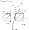
- ball joint connection essentially comprises a ball pin 12 with a ball joint 14, via a socket 16 in a through hole 18 of a Vehicle component 20 is guided and releasably connected to the vehicle component 20.
- the bushing 16 has a bushing flange 22 and is arranged in the through hole 18 such that the bushing flange 22 of the bush rests on an associated contact surface 24 of the vehicle component 20.
- the ball-and-socket joint 10 known from the prior art proves to be disadvantageous, since a radial force F R acting on the joint ball 14 leads to a stress concentration in the edge region of the through-bore 18 facing the joint ball 14, symbolized here by reference number 26. This stress concentration in the region 26 can lead to cracking and thus premature failure of the vehicle component 20.
- a gap 27 extending in the axial direction a is arranged between the end region of the vehicle component 20 facing the joint ball 14 and the end region of the bush 16 facing the joint ball 14.
- the inventive arrangement of the gap 27 ensures that the stresses caused by radial forces F R are no longer concentrated on the region 26 of the vehicle component 20, but are displaced into a region 29 in the interior of the vehicle component 20.
- the gap 29 is formed by a, only introduced into the bush 16, radially encircling groove 31.
- the groove 31 can also be formed by a groove 31 which is arranged only in the vehicle component 20 or by two oppositely disposed respectively in the bushing 16 and the vehicle component 20.
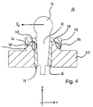
- the bushing flange 22 is pot-shaped, ie the bushing flange 22 comprises a bottom region 28 and a wall region 30 and only the wall region 30 of the cup-shaped bushing flange 22 lies on the correspondingly formed contact surface 24 of the vehicle component 20 on, while between the end face of the vehicle component 20 and the bottom portion 28 of the cup-shaped bushing flange 22, a gap 32 remains.
- the embodiment according to the invention of the bushing flange 22 and the associated contact surface 24 ensures that the stresses caused by radial forces F R are no longer concentrated exclusively on the region 26 of the vehicle component 20 but are additionally distributed over a further region 34 of the vehicle component 20.
- the resulting stress distribution thus reduces the local stresses in the region 26 and thus prevents crack formation in this region, so that a longer service life of the vehicle component 20 is ensured.
- the wall portion 30 of the cup-shaped bushing flange 22 and the corresponding thereto formed contact surface 24 of the vehicle component 20 are formed cone-shaped.
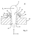
- FIG. 4 A further embodiment of the ball joint connection 10 according to the invention is shown in FIG. 4.
- the pot-shaped bushing flange 22 is designed differently in the case of the ball joint connection 10 shown in FIG. 3.
- the wall portion 30 of the Buchsenflansches 22 and the corresponding thereto formed contact surface 24 of the vehicle component 20 are formed dome-shaped.
- bushing flange 22 and contact surface 24 of the vehicle component 20 ensures that the bottom portion 28 of the Buchsenflansches 22 does not rest on the end face of the contact surface 24 of the vehicle component 20, but are positively connected to each other only via the Kalotten vom.
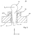
- FIG. 5 A further embodiment of the ball and socket joint 10 according to the invention is shown in FIG. 5.
- a gap 27 which has already been described above and which extends in the axial direction a is arranged ,
- the gap 38 causes an additional stress displacement of the stresses caused by the radial force F R in the region 29 in the interior of the vehicle component 20. This ensures a uniform distribution of stress over the entire vehicle component 20, which increases the risk of cracking in the vehicle component 20 additionally reduces and thus contributes to an increase in the service life of the vehicle component 20.
- the gap 27 has a length of about 1/4 to 1/3 of the diameter of the through hole 18 while viewed in the radial direction r, the gap 27 has a thickness of preferably 1mm.
- the illustrated ball pin 12 has a conical outer surface and the bush 16 has a conical inner surface which corresponds to it.
- the outer circumferential surface of the ball pin 12 and the correspondingly formed inner circumferential surface of the sleeve 16 may also be cylindrical.
- the bushing 16 is made of steel and the vehicle component 20 is made of aluminum, and the bush 16 guided in the through hole 18 of the vehicle component 20 is pressed into the vehicle component 20.
- the socket 16 may also be screwed into the vehicle component 20.
- the releasable connection of the ball pin 12 with the vehicle component 20 is in the ball joint connection 10 shown in FIGS. 2 to 5 according to the invention realized in each case by a, not shown here for clarity, screw that in an opposing ball 14 opposite portion of the ball pin 12th is arranged.
- the invention is characterized in that the local stress peaks in the region of the joint ball 14 facing edge region of the vehicle component 20 are degraded by targeted structural measures, whereby the risk of cracking minimized and thus a longer life of the vehicle component 20 is ensured.
Landscapes
- Engineering & Computer Science (AREA)
- General Engineering & Computer Science (AREA)
- Mechanical Engineering (AREA)
- Pivots And Pivotal Connections (AREA)
Abstract
Description
Die Erfindung betrifft eine Kugelgelenkverbindung gemäß der im Oberbegriff des Anspruchs 1 angegebenen Art.The invention relates to a ball joint connection according to the type specified in the preamble of claim 1.
Eine gattungsgemäße Kugelgelenkverbindung ist in der
In der
Als nachteilig erweist sich bei den bekannten Kugelgelenkverbindungen die ungünstige Krafteinleitung und der daraus resultierende ungünstige Spannungsverlauf im Bauteil, da die durch eine an der Gelenkkugel angreifenden Radialkraft resultierenden Spannungen sich auf den der Gelenkkugel zugewandten Randbereich der Durchgangsbohrung/ -öffnung des Bauteils konzentrieren. Diese Spannungskonzentration im Randbereich des Bauteils kann zu Rissbildung und somit zu einem frühzeitigen Versagen des Bauteils in diesem Bereich führen.A disadvantage is found in the known ball joint compounds the unfavorable force and the resulting unfavorable voltage curve in the component, since the stresses resulting from acting on the joint ball radial force stresses focus on the joint ball facing edge region of the through hole / opening of the component. This stress concentration in the edge region of the component can lead to cracking and thus to premature failure of the component in this area.
Der Erfindung liegt die Aufgabe zugrunde, eine Kugelgelenkverbindung gemäß der im Oberbegriff des Anspruchs 1 angegebenen Art unter Vermeidung der genannten Nachteile derart weiterzubilden, dass die Gefahr zur Rissbildung und zu einem frühzeitigen Versagen des Bauteils vermindert wird.The invention has the object of developing a ball joint connection according to the type specified in the preamble of claim 1 while avoiding the disadvantages mentioned in such a way that the risk of cracking and premature failure of the component is reduced.
Diese Aufgabe wird durch die kennzeichnenden Merkmale des Anspruchs 1 in Verbindung mit seinen Oberbegriffsmerkmalen gelöst.This object is achieved by the characterizing features of claim 1 in conjunction with its preamble features.
Eine weitere Lösung der Aufgabe ist in den kennzeichnenden Merkmalen des Anspruchs 2 in Verbindung mit den Oberbegriffsmerkmalen des Anspruches 1 angegeben.A further solution of the problem is specified in the characterizing features of claim 2 in conjunction with the preamble features of claim 1.
Die Unteransprüche bilden vorteilhafte Weiterbildungen der Erfindung.The dependent claims form advantageous developments of the invention.
Der Erfindung liegt die Erkenntnis zugrunde, dass durch eine gezielte Reduktion der durch eine an der Gelenkkugel angreifende Radialkraft hervorgerufenen Spannungen in dem der Gelenkkugel zugewandten Randbereich der Durchgangsbohrung/ -öffnung des Bauteils die Gefahr einer Rissbildung in diesem Bereich vermindert wird und damit eine längere Lebensdauer des Bauteils gewährleistet ist.The invention is based on the finding that by a targeted reduction of the stresses caused by a radial force acting on the joint ball in the edge region of the joint ball facing the joint ball Through hole / opening of the component, the risk of cracking in this area is reduced and thus a longer life of the component is ensured.
Hierfür umfasst die Kugelgelenkverbindung einen Kugelzapfen mit einer Gelenkkugel, wobei der Kugelzapfen über eine Buchse in einer Durchgangsbohrung eines Fahrzeugbauteiles geführt ist und lösbar mit dem Fahrzeugbauteil verbunden ist. Die Buchse weist in einem der Gelenkkugel zugewandten Endbereich einen Buchsenflansch auf, wobei der Buchsenflansch auf einer Kontaktfläche des Fahrzeugbauteils aufliegt. Erfindungsgemäß ist zwischen dem der Gelenkkugel zugewandten Endbereich des Fahrzeugbauteils und dem der Gelenkkugel zugewandten Endbereich der Buchse ein in axiale Richtung verlaufender Spalt angeordnet. Auf eine einfache Art und Weise ist nunmehr eine Spannungsreduktion in dem der Gelenkkugel zugewandten Randbereich der Durchgangsbohrung des Fahrzeugbauteils gewährleistet, da durch den erfindungsgemäß angeordneten Spalt die durch eine an der Gelenkkugel angreifende Radialkraft hervorgerufenen Spannungen von dem der Gelenkkugel zugewandten Randbereich der Durchgangsbohrung des Fahrzeugbauteils in das Innere des Fahrzeugbauteils verlagert werden. Als Folge davon ergibt sich eine gleichmäßige, großflächige Spannungsverteilung aus dem Randbereich des Fahrzeugbauteils ins Bauteilinnere. Die gleichmäßige Spannungsverteilung reduziert die Gefahr einer Rissbildung in dem der Gelenkkugel zugewandten Randbereich der Durchgangsbohrung des Fahrzeugbauteils und wirkt sich somit positiv auf die Lebensdauer des Fahrzeugbauteils aus. Durch den erfindungsgemäß angeordneten Spalt und die dadurch bedingte Aussparung im Randbereich der Verbindung wird zudem noch in Vorteilhafterweise eine Gewichts- und Kostenreduktion erzielt.For this purpose, the ball joint connection comprises a ball stud with a ball joint, wherein the ball stud is guided via a bush in a through hole of a vehicle component and is detachably connected to the vehicle component. The bushing has a bushing flange in an end region facing the ball joint, wherein the bushing flange rests on a contact surface of the vehicle component. According to the invention, a gap extending in the axial direction is arranged between the end region of the vehicle component facing the joint ball and the end region of the bush facing the joint ball. In a simple way, a stress reduction in the joint ball facing edge region of the through hole of the vehicle component is guaranteed, as caused by a radial force acting on the joint ball stresses caused by the radial force acting on the joint ball of the joint ball facing edge region of the through hole of the vehicle component in the Interior of the vehicle component to be relocated. As a result, a uniform, large-scale stress distribution results from the edge region of the vehicle component into the component interior. The uniform stress distribution reduces the risk of cracking in the edge region of the through hole of the vehicle component facing the joint ball and thus has a positive effect on the service life of the vehicle component. By the inventively arranged gap and thereby Conditional recess in the edge region of the connection is also still achieved advantageously a weight and cost reduction.
Nach einer zweiten erfindungsgemäßen Lösung ist der Buchsenflansch topfförmig, einen Boden- und Wandbereich aufweisend, ausgebildet und lediglich der Wandbereich des topfförmig ausgebildeten Buchsenflansches liegt auf der dazu korrespondierend ausgebildeten Kontaktfläche des Fahrzeugbauteils auf. Hierdurch ist auf eine einfache Art und Weise eine Spannungsreduktion in dem der Gelenkkugel zugewandten Randbereich der Durchgangsbohrung des Fahrzeugbauteils gewährleistet, da die durch eine an der Gelenkkugel angreifende Radialkraft hervorgerufenen Spannungen sich nicht ausschließlich auf den der Gelenkkugel zugewandten Randbereich der Durchgangsbohrung des Fahrzeugbauteils konzentrieren, sondern sich zusätzlich auf den Wandbereich des Buchsenflansches verteilen. Die Folge daraus sind niedrigere lokale Spannungen in dem Fahrzeugbauteil, was die Gefahr einer Rissbildung reduziert und somit einer längeren Lebensdauer des Fahrzeugbauteils gewährleistet.According to a second solution according to the invention, the bushing flange is pot-shaped, having a bottom and wall region, and only the wall region of the pot-shaped bushing flange rests on the contact surface of the vehicle component that corresponds to it. As a result, a stress reduction in the joint ball facing edge region of the through hole of the vehicle component is ensured in a simple manner, as caused by a radial force acting on the joint ball stresses are not concentrated exclusively on the joint ball facing edge region of the through hole of the vehicle component, but themselves additionally distribute to the wall area of the bushing flange. The consequence of this is lower local stresses in the vehicle component, which reduces the risk of cracking and thus ensures a longer service life of the vehicle component.
Gemäß einer Ausführungsform der Erfindung sind hierbei der Wandbereich des Buchsenflansches und die Kontaktfläche des Fahrzeugbauteils kegelförmig ausgebildet. Die kegelförmige Ausgestaltung dieser Flächen erweist sich als vorteilhaft, da diese fertigungstechnisch einfach herzustellen sind.According to one embodiment of the invention, in this case the wall region of the bushing flange and the contact surface of the vehicle component are formed conically. The conical configuration of these surfaces proves to be advantageous because these production technology are easy to manufacture.
Gemäß einer anderen Ausführungsform der Erfindung sind der Wandbereich des Buchsenflansches und die Kontaktfläche des Fahrzeugbauteils kalottenförmig ausgebildet.According to another embodiment of the invention, the wall portion of the bushing flange and the contact surface of the vehicle component are formed dome-shaped.
Die kalottenförmige Ausbildung erweist sich als vorteilhaft, da hierdurch eine größere Kontaktfläche zwischen dem Wandbereich des Buchsenflansches und dem Fahrzeugbauteil zur Verfügung steht, was einer weitere Senkung des lokalen Spannungsniveaus in dem der Gelenkkugel zugewandten Randbereich der Durchgangsbohrung des Fahrzeugbauteils bedingt.The dome-shaped design proves to be advantageous, as a result, a larger contact area between the wall portion of the Buchsenflansches and the vehicle component is available, causing a further reduction of the local stress level in the joint ball facing edge region of the through hole of the vehicle component.
Vorzugsweise ist auch bei der zweiten erfindungsgemäßen Lösung zwischen dem der Gelenkkugel zugewandten Endbereich des Fahrzeugbauteils und dem der Gelenkkugel zugewandten Endbereich der Buchse ein in axialer Richtung verlaufender Spalt angeordnet. Durch den Spalt ist in einer besonders vorteilhaften Weise eine zusätzliche Spannungsverlagerung bedingt, da, wie bereits dargelegt wurde, durch den Spalt die auftretendenden Spannungen von dem der Gelenkkugel zugewandten Randbereich der Durchgangsbohrung des Fahrzeugbauteils in das Innere des Fahrzeugbauteils verlagert werden.Preferably, in the second solution according to the invention, a gap extending in the axial direction is also arranged between the end region of the vehicle component facing the joint ball and the end region of the bush facing the joint ball. Through the gap, an additional voltage displacement is due in a particularly advantageous manner, since, as already stated, the voltages occurring are displaced by the edge of the through hole of the vehicle component facing the ball joint in the interior of the vehicle component through the gap.
Der Einfachheithalber ist der zwischen dem der Gelenkkugel zugewandten Endbereich des Fahrzeugbauteils und dem der Gelenkkugel zugewandten Endbereich der Buchse angeordnete Spalt durch eine radial umlaufende Nut gebildet. Vorzugsweise ist dabei die Nut in den der Gelenkkugel zugewandten Endbereich des Fahrzeugbauteils und/oder in den der Gelenkkugel zugewandten Endbereich der Buchse eingebracht.For the sake of simplicity, the gap arranged between the end of the vehicle component facing the joint ball and the end region of the bush facing the joint ball is formed by a radially circumferential groove. In this case, the groove is preferably introduced into the end region of the vehicle component facing the joint ball and / or into the end region of the bush facing the joint ball.
Um die durch den Spalt beabsichtigte Spannungsreduzierung zu gewährleisten, weist der Spalt in axiale Richtung betrachtet eine Länge von etwa 1/4 bis 1/3 des Durchmessers der Durchgangsbohrung und in radiale Richtung betrachtet eine Breite von etwa 0,1 mm bis 2 mm, insbesondere aber 1 mm, auf.In order to ensure the intended by the gap voltage reduction, the gap in the axial direction considered a length of about 1/4 to 1/3 of the diameter of the through hole and in the radial direction considers a width of about 0.1 mm to 2 mm, but in particular 1 mm.
Vorzugsweise weist der Kugelzapfen eine konische oder zylindrische Außenmantelfläche und die Buchse eine dazu korrespondierend ausgebildete zylindrische oder konische Innenmantelfläche auf.Preferably, the ball stud has a conical or cylindrical outer lateral surface and the bush has a cylindrical or conical inner lateral surface corresponding thereto.
Gemäß einer weiteren Ausführungsform der Erfindung ist in einem der Gelenkkugel gegenüberliegende Bereich des Kugelzapfens eine Schraubverbindung angeordnet, über die der Kugelzapfen lösbar mit dem Fahrzeugbauteil verbunden ist.According to a further embodiment of the invention, a screw connection is arranged in a region of the ball pin opposite the joint ball, via which the ball pin is detachably connected to the vehicle component.
Um einen sicheren Sitz der Buchse in dem Fahrzeugbauteil zu gewährleisten, ist die Buchse vorzugsweise in das Fahrzeugbauteil eingepresst oder eingeschraubt.In order to ensure a secure fit of the bushing in the vehicle component, the bushing is preferably pressed or screwed into the vehicle component.
Vorzugsweise sind die Buchse und das Fahrzeugbauteil aus unterschiedlichen Bauteilen gefertigt, insbesondere die Buchse aus Stahl und das Bauteil aus Aluminium.Preferably, the socket and the vehicle component are made of different components, in particular the bush made of steel and the component made of aluminum.
Weitere Vorteile, Merkmale und Anwendungsmöglichkeiten der vorliegenden Erfindung ergeben sich aus der nachfolgenden Beschreibung in Verbindung mit den in der Zeichnung dargestellten Ausführungsbeispielen.Further advantages, features and applications of the present invention will become apparent from the following description in conjunction with the embodiments illustrated in the drawings.
Die Erfindung wird im folgenden anhand der in der Zeichnung dargestellten Ausführungsbeispielen näher beschrieben. In der Beschreibung, in den Ansprüchen und in der Zeichnung werden die in der hinten angeführten Liste der Bezugszeichen verwendeten Begriffe und zugeordnete Bezugszeichen verwendet.The invention is described below with reference to the embodiments illustrated in the drawings. In the description, in the claims and in the drawing, the terms and associated reference numerals used in the list of reference numerals recited below are used.
In der Zeichnung bedeutet:
- Fig. 1
- eine schematische Schnittdarstellung einer Kugelgelenkverbindung nach dem Stand der Technik;
- Fig. 2
- eine schematische Schnittdarstellung einer erfindungsgemäßen Kugelgelenkverbindung, bei der zwischen Buchse und Fahrzeugbauteil ein Spalt angeordnet ist;
- Fig. 3
- eine schematische Schnittdarstellung einer weiteren erfindungsgemäßen Kugelgelenkverbindung, bei der der Wandbereich des Buchsenflansches und die Kontaktfläche des Fahrzeugbauteils kegelförmig ausgebildet sind;
- Fig.4
- eine weitere Ausführungsform der erfindungsgmäßen Kugelgelenkverbindung, bei der der Wandbereich des Buchsenflansches und die Kontaktfläche des Fahrzeugbauteils kalottenförmig ausgebildet sind;
- Fig. 5
- die Kugelgelenkverbindung aus Fig. 4, wobei zwischen Buchse und Fahrzeugbauteil zusätzlich ein Spalt angeordnet ist.
- Fig. 1
- a schematic sectional view of a ball joint connection according to the prior art;
- Fig. 2
- a schematic sectional view of a ball joint connection according to the invention, in which a gap is arranged between the socket and the vehicle component;
- Fig. 3
- a schematic sectional view of another ball joint connection according to the invention, in which the wall portion of the Buchsenflansches and the contact surface of the vehicle component are formed conically;
- Figure 4
- a further embodiment of erfindungsgmäßen ball joint connection, in which the wall portion of the bushing flange and the contact surface of the vehicle component are formed dome-shaped;
- Fig. 5
- the ball joint of Fig. 4, wherein between the socket and vehicle component additionally a gap is arranged.
Die in Fig. 1 in einer vereinfachten Schnittdarstellung mehr oder minder schematisch dargestellte, insgesamt mit der Bezugsziffer 10 bezeichnete, Kugelgelenkverbindung nach dem Stand der Technik umfasst im Wesentlichen einen Kugelzapfen 12 mit einer Gelenkkugel 14, der über eine Buchse 16 in einer Durchgangsbohrung 18 eines Fahrzeugbauteils 20 geführt und lösbar mit dem Fahrzeugbauteil 20 verbunden ist. Die Buchse 16 weist einen Buchsenflansch 22 auf und ist so in der Durchgangsbohrung 18 angeordnet, dass der Buchsenflansch 22 der Buchse auf einer zugeordneten Kontaktfläche 24 des Fahrzeugbauteils 20 aufliegt.The illustrated in Fig. 1 in a simplified sectional view more or less schematically, generally designated by the
Die aus dem Stand der Technik bekannte Kugelgelenkverbindung 10 erweist sich als nachteilig, da eine an der Gelenkkugel 14 angreifende Radialkraft FR zu einer Spannungskonzentration in dem der Gelenkkugel 14 zugewandten Randbereich der Durchgangsbohrung 18, vorliegend durch Bezugszeichen 26 symbolisiert, führt. Diese Spannungskonzentration in dem Bereich 26 kann zu einer Rissbildung und somit einem frühzeitigen Versagen des Fahrzeugbauteils 20 führen.The ball-and-
Zur Vermeidung dieser Nachteile ist gemäß einer ersten erfindungsgemäßen Kugelgelenkverbindung 10 nach Fig. 2 zwischen dem der Gelenkkugel 14 zugewandten Endbereich des Fahrzeugbauteils 20 und dem der Gelenkkugel 14 zugewandten Endbereich der Buchse 16 ein in axiale Richtung a verlaufender Spalt 27 angeordnet. Durch die erfindungsgemäße Anordnung des Spaltes 27 ist sichergestellt, dass die durch Radialkräfte FR hervorgerufenen Spannungen sich nicht mehr auf den Bereich 26 des Fahrzeugbauteils 20 konzentrieren, sondern in einen Bereich 29 im Innern des Fahrzeugbauteils 20 verlagert werden. Als Folge davon ergibt sich eine gleichmäßige Spannungsverteilung über das gesamte Fahrzeugbauteil 20, was die Gefahr einer Rissbildung in dem Fahrzeugbauteil 20 reduziert, sodass eine längere Lebensdauer des Fahrzeugbauteils 20 gewährleistet ist.To avoid these disadvantages, according to a first ball and
Gemäß dem dargestellten Ausführungsbeispiel in Fig. 2 ist der Spalt 29 durch eine, lediglich in die Buchse 16 eingebrachte, radial umlaufende Nut 31 gebildet. Die Nut 31 kann aber auch durch eine lediglich in das Fahrzeugbauteil 20 oder durch zwei gegenüberliegend angeordnete, jeweils in die Buchse 16 und das Fahrzeugbauteil 20 eingebrachte Nut 31 gebildet sein.According to the illustrated embodiment in Fig. 2, the
Gemäß einer zweiten erfindungsgemäßen Kugelgelenkverbindung 10 nach Fig. 3 ist der Buchsenflansch 22 topfförmig ausgebildet, d.h., der Buchsenflansch 22 umfasst einen Bodenbereich 28 und einen Wandbereich 30 und lediglich der Wandbereich 30 des topfförmig ausgebildeten Buchsenflansches 22 liegt auf der korrespondierend ausgebildeten Kontaktfläche 24 des Fahrzeugbauteils 20 auf, während zwischen der Stirnfläche des Fahrzeugbauteils 20 und dem Bodenbereich 28 des topfförmig ausgebildeten Buchsenflansches 22 ein Spalt 32 verbleibt.According to a second ball-and-
Durch die erfindungsgemäße Ausgestaltung des Buchsenflansches 22 und der zugeordneten Kontaktfläche 24 ist sichergestellt, dass die durch Radialkräfte FR hervorgerufenen Spannungen sich nicht mehr ausschließlich auf den Bereich 26 des Fahrzeugbauteils 20 konzentrieren, sondern sich zusätzlich auf einen weiteren Bereich 34 des Fahrzeugbauteils 20 verteilen. Die dadurch erzielte Spannungsverteilung reduziert somit die lokalen Spannungen in dem Bereich 26 und beugt damit einer Rissbildung in diesem Bereich vor, sodass eine längere Lebensdauer des Fahrzeugbauteils 20 gewährleistet ist.The embodiment according to the invention of the
Bei dem in Fig. 3 dargestellten Ausführungsbeispiel sind der Wandbereich 30 des topfförmigen Buchsenflansches 22 und die dazu korrespondierend ausgebildete Kontaktfläche 24 des Fahrzeugbauteils 20 kegelförmig ausgebildet.In the embodiment shown in Fig. 3, the
Eine weiteres Ausführungsbeispiel der erfindungsgemäßen Kugelgelenkverbindung 10 ist in Fig. 4 dargestellt. Im Unterschied zu Fig. 3 ist bei der in Fig. 3 dargestellten Kugelgelenkverbindung 10 der topfförmige Buchsenflansch 22 anders ausgebildet. Entsprechend dieser Ausführungsform sind der Wandbereich 30 des Buchsenflansches 22 und die dazu korrespondierend ausgebildete Kontaktfläche 24 des Fahrzeugbauteils 20 kalottenförmig ausgebildet. Auch bei dieser Ausgestaltung von Buchsenflansch 22 und Kontaktfläche 24 des Fahrzeugbauteils 20 ist gewährleistet, dass der Bodenbereich 28 des Buchsenflansches 22 nicht auf der Stirnfläche der Kontaktfläche 24 des Fahrzeugbauteils 20 aufliegt, sondern lediglich über die Kalottenflächen formschlüssig miteinander verbunden sind. Die bereits oben geschilderten Vorteile treten entsprechend auch bei dieser Ausführungsform aus.A further embodiment of the ball
Eine weitere Ausführungsform der erfindungsgemäßen Kugelgelenkverbindung 10 zeigt Fig. 5. Hierbei ist zwischen dem der Gelenkkugel 14 zugewandten Endbereich des Fahrzeugbauteils 20 und dem der Gelenkkugel 14 zugewandten Endbereich der Buchse 16 zusätzlich ein, bereits weiter oben beschriebener, in axiale Richtung a verlaufender Spalt 27 angeordnet.A further embodiment of the ball and socket joint 10 according to the invention is shown in FIG. 5. In this case, between the end region of the
Wie bereits ausgeführt wurde, bedingt der Spalt 38 eine zusätzliche Spannungsverlagerung der durch die Radialkraft FR hervorgerufenen Spannungen in den Bereich 29 im Innern des Fahrzeugbauteils 20. Hierdurch ist eine gleichmäßige Spannungsverteilung über das gesamte Fahrzeugbauteil 20 gewährleistet, was die Gefahr einer Rissbildung in dem Fahrzeugbauteil 20 zusätzlich reduziert und damit zu einer Erhöhung der Lebensdauer des Fahrzeugbauteils 20 beiträgt.As already stated, the gap 38 causes an additional stress displacement of the stresses caused by the radial force F R in the
In axiale Richtung a betrachtet weist der Spalt 27 eine Länge von etwa 1/4 bis 1/3 des Durchmessers der Durchgangsbohrung 18 auf während in radiale Richtung r betrachtet der Spalt 27 eine Dicke von vorzugsweise 1mm aufweist.Viewed in the axial direction a, the gap 27 has a length of about 1/4 to 1/3 of the diameter of the through
Wie aus den Fig. 2 bis 5 der erfindungsgemäßen Kugelgelenkverbindung 10 ersichtlich ist, weist der dargestellte Kugelzapfen 12 eine konische Außenmantelfläche und die Buchse 16 eine dazu korrespondierend ausgebildete konische Innenmantelfläche auf. Die Außenmantelfläche des Kugelzapfens 12 und die dazu korrespondierend ausgebildete Innenmantelfläche der Buchse 16 können aber auch zylindrisch ausgebildet sein.As can be seen from FIGS. 2 to 5 of the ball-and-
In den oben beschriebenen Ausführungsspielen der Kugelgelenkverbindung 10 ist die Buchse 16 aus Stahl und das Fahrzeugbauteil 20 aus Aluminium gefertigt und die in der Durchgangsbohrung 18 des Fahrzeugbauteils 20 geführten Buchse 16 ist in das Fahrzeugbauteil 20 eingepresst. Die Buchse 16 kann jedoch auch in das Fahrzeugbauteil 20 eingeschraubt sein.In the above-described embodiments of the ball
Die lösbare Verbindung des Kugelzapfens 12 mit dem Fahrzeugbauteil 20 ist bei der in den Fig. 2 bis 5 dargestellten erfindungsgemäßen Kugelgelenkverbindung 10 jeweils durch eine, hier aus Gründen der Übersichtlichkeit nicht dargestellte, Schraubverbindung realisiert, die in einem der Gelenkkugel 14 gegenüberliegenden Bereich des Kugelzapfens 12 angeordnet ist.The releasable connection of the
Die Erfindung zeichnet sich dadurch aus, dass durch gezielte konstruktive Maßnahmen die lokalen Spannungsspitzen im Bereich des der Gelenkkugel 14 zugewandeten Randbereich des Fahrzeugbauteils 20 abgebaut werden, wodurch die Gefahr einer Rissbildung minimiert und somit eine höhere Lebensdauer des Fahrzeugbauteils 20 gewährleistet wird.The invention is characterized in that the local stress peaks in the region of the
- 1010
- KugelgelenkverbindungBall joint
- 1212
- Kugelzapfenball pin
- 1414
- Gelenkkugeljoint ball
- 1616
- BuchseRifle
- 1818
- DurchgangsbohrungThrough Hole
- 2020
- Fahrzeugbauteilvehicle component
- 2222
- Buchsenflanschbushing flange
- 2424
- Kontaktfläche des FahrzeugbauteilsContact surface of the vehicle component
- 2626
- Bereich der SpannungskonzentrationRange of stress concentration
- 2727
- Spaltgap
- 2828
- Bodenbereich des BuchsenflanschesBottom area of the bushing flange
- 2929
- Bereich im Innern des FahrzeugbauteilsArea inside the vehicle component
- 3030
- Wandbereich des BuchsenflanschesWall area of the bushing flange
- 3131
- umlaufende Nutcircumferential groove
- 3232
- Spalt zwischen Stirnfläche des Fahrzeugbauteils und Bodenbereich des BuchsenflanschesGap between the end face of the vehicle component and the bottom portion of the bushing flange
- 3434
- weiterer Bereich des Fahrzeugbauteilsfurther area of the vehicle component
- FR F R
- Radialkraftradial force
- aa
- axiale Richtungaxial direction
- rr
- radiale Richtungradial direction
Claims (12)
Applications Claiming Priority (2)
| Application Number | Priority Date | Filing Date | Title |
|---|---|---|---|
| DE102005018153 | 2005-04-20 | ||
| DE102005039402A DE102005039402B3 (en) | 2005-04-20 | 2005-08-20 | Ball joint |
Publications (3)
| Publication Number | Publication Date |
|---|---|
| EP1715200A2 true EP1715200A2 (en) | 2006-10-25 |
| EP1715200A3 EP1715200A3 (en) | 2008-01-23 |
| EP1715200B1 EP1715200B1 (en) | 2011-05-04 |
Family
ID=36729338
Family Applications (1)
| Application Number | Title | Priority Date | Filing Date |
|---|---|---|---|
| EP06002018A Not-in-force EP1715200B1 (en) | 2005-04-20 | 2006-02-01 | Ball joint connection |
Country Status (2)
| Country | Link |
|---|---|
| EP (1) | EP1715200B1 (en) |
| DE (2) | DE102005039402B3 (en) |
Cited By (1)
| Publication number | Priority date | Publication date | Assignee | Title |
|---|---|---|---|---|
| CN113428221A (en) * | 2021-07-09 | 2021-09-24 | 重庆长安汽车股份有限公司 | Flexible connecting structure of automobile steering pull rod |
Families Citing this family (3)
| Publication number | Priority date | Publication date | Assignee | Title |
|---|---|---|---|---|
| DE102008061511A1 (en) | 2008-12-10 | 2010-06-17 | Daimler Ag | Ball joint arrangement for motor vehicle, has force transmission element accommodated in recess of structural component i.e. housing, and receiving opening provided to receive ball pin that is provided adjacent to ball joint |
| DE102010023470A1 (en) | 2010-06-11 | 2011-12-15 | Dr. Ing. H.C. F. Porsche Aktiengesellschaft | Support structure for pivot pin for motor vehicle, is guided in through hole by bushing, where passing guide is formed in axial guide section between bushing and pivot pin |
| DE102011001498A1 (en) | 2011-03-23 | 2012-09-27 | Dr. Ing. H.C. F. Porsche Aktiengesellschaft | Support and guide structure for motor car, has pivot pin has supporting portion that is formed in axial distance from conical seat for supporting lateral force, bending moment or tilting moment of conical seat |
Citations (2)
| Publication number | Priority date | Publication date | Assignee | Title |
|---|---|---|---|---|
| DE19622047C2 (en) | 1995-06-02 | 2002-02-14 | Toyota Motor Co Ltd | Ball joint with an extended service life |
| DE19950281B4 (en) | 1999-10-19 | 2004-02-05 | Sachsenring Fahrzeugtechnik Gmbh | ball joint |
Family Cites Families (4)
| Publication number | Priority date | Publication date | Assignee | Title |
|---|---|---|---|---|
| DE931929C (en) * | 1952-06-28 | 1955-08-18 | Ehrenreich & Cie A | Adjustable steering lever, especially for motor vehicles |
| JPH0443622Y2 (en) * | 1988-03-04 | 1992-10-15 | ||
| DE3842609A1 (en) * | 1988-12-17 | 1990-06-21 | Stabilus Gmbh | Ball-headed pivot of a ball-and-socket joint |
| DE20120096U1 (en) * | 2001-12-10 | 2002-03-21 | Sachsenring Fahrzeugtechnik GmbH, 08058 Zwickau | Sealing for a ball joint |
-
2005
- 2005-08-20 DE DE102005039402A patent/DE102005039402B3/en not_active Expired - Fee Related
-
2006
- 2006-02-01 EP EP06002018A patent/EP1715200B1/en not_active Not-in-force
- 2006-02-01 DE DE502006009421T patent/DE502006009421D1/en active Active
Patent Citations (2)
| Publication number | Priority date | Publication date | Assignee | Title |
|---|---|---|---|---|
| DE19622047C2 (en) | 1995-06-02 | 2002-02-14 | Toyota Motor Co Ltd | Ball joint with an extended service life |
| DE19950281B4 (en) | 1999-10-19 | 2004-02-05 | Sachsenring Fahrzeugtechnik Gmbh | ball joint |
Cited By (1)
| Publication number | Priority date | Publication date | Assignee | Title |
|---|---|---|---|---|
| CN113428221A (en) * | 2021-07-09 | 2021-09-24 | 重庆长安汽车股份有限公司 | Flexible connecting structure of automobile steering pull rod |
Also Published As
| Publication number | Publication date |
|---|---|
| DE502006009421D1 (en) | 2011-06-16 |
| EP1715200A3 (en) | 2008-01-23 |
| DE102005039402B3 (en) | 2006-11-02 |
| EP1715200B1 (en) | 2011-05-04 |
Similar Documents
| Publication | Publication Date | Title |
|---|---|---|
| EP1727647B1 (en) | Centering pin | |
| DE4033763C2 (en) | Device for securing a nut received in an opening in a panel | |
| EP2783119B1 (en) | Device for introducing force into a component of fibre composite material | |
| DE2424262A1 (en) | THREADLESS CLAMPING DEVICE | |
| DE102012107546A1 (en) | tooling | |
| EP3206898B1 (en) | Connecting arrangement for a stabilizer of a vehicle | |
| DE202008000982U1 (en) | Threaded insert and vehicle part | |
| DE102013215291A1 (en) | Threaded bush for screwing in | |
| EP1715200B1 (en) | Ball joint connection | |
| DE2143379A1 (en) | Torque transmitting flexible coupling | |
| DE102008055518A1 (en) | joint | |
| WO2015120976A1 (en) | Machine element | |
| EP1741953B1 (en) | Vibration damper with rebound stop spring element | |
| DE202004012473U1 (en) | Metallic cutting ring | |
| EP3642501B1 (en) | Connection comprising a hollow shaft, a shaft and a collar on the hollow shaft; planetary gear | |
| DE202004016599U1 (en) | Combination of convex nut and concave compensating washer to be used for bolt inserted in slightly inclined position into curved work-piece | |
| EP1226894B1 (en) | Device for connecting a tool head to a clamping shaft | |
| DE102004029581B4 (en) | Central joint for a wishbone of motor vehicles | |
| DE1961980B2 (en) | Hub attachment | |
| EP3428496A1 (en) | Operating element and assembly comprising a control element | |
| EP3624286B1 (en) | Base lower part for electroinstallation devices | |
| DE202016101870U1 (en) | Stator for eccentric screw machine | |
| DE19724242C2 (en) | mother | |
| DE19823475A1 (en) | Automotive fixture joining esp. cylinder head valve cover to a cylinder head | |
| DE102022115093A1 (en) | Ultrasonic welding system with clamping device |
Legal Events
| Date | Code | Title | Description |
|---|---|---|---|
| PUAI | Public reference made under article 153(3) epc to a published international application that has entered the european phase |
Free format text: ORIGINAL CODE: 0009012 |
|
| AK | Designated contracting states |
Kind code of ref document: A2 Designated state(s): AT BE BG CH CY CZ DE DK EE ES FI FR GB GR HU IE IS IT LI LT LU LV MC NL PL PT RO SE SI SK TR |
|
| AX | Request for extension of the european patent |
Extension state: AL BA HR MK YU |
|
| PUAL | Search report despatched |
Free format text: ORIGINAL CODE: 0009013 |
|
| AK | Designated contracting states |
Kind code of ref document: A3 Designated state(s): AT BE BG CH CY CZ DE DK EE ES FI FR GB GR HU IE IS IT LI LT LU LV MC NL PL PT RO SE SI SK TR |
|
| AX | Request for extension of the european patent |
Extension state: AL BA HR MK YU |
|
| 17P | Request for examination filed |
Effective date: 20080723 |
|
| AKX | Designation fees paid |
Designated state(s): DE FR GB IT |
|
| 17Q | First examination report despatched |
Effective date: 20080908 |
|
| GRAP | Despatch of communication of intention to grant a patent |
Free format text: ORIGINAL CODE: EPIDOSNIGR1 |
|
| GRAS | Grant fee paid |
Free format text: ORIGINAL CODE: EPIDOSNIGR3 |
|
| GRAA | (expected) grant |
Free format text: ORIGINAL CODE: 0009210 |
|
| AK | Designated contracting states |
Kind code of ref document: B1 Designated state(s): DE FR GB IT |
|
| REG | Reference to a national code |
Ref country code: GB Ref legal event code: FG4D Free format text: NOT ENGLISH |
|
| REF | Corresponds to: |
Ref document number: 502006009421 Country of ref document: DE Date of ref document: 20110616 Kind code of ref document: P |
|
| REG | Reference to a national code |
Ref country code: DE Ref legal event code: R096 Ref document number: 502006009421 Country of ref document: DE Effective date: 20110616 |
|
| PLBE | No opposition filed within time limit |
Free format text: ORIGINAL CODE: 0009261 |
|
| STAA | Information on the status of an ep patent application or granted ep patent |
Free format text: STATUS: NO OPPOSITION FILED WITHIN TIME LIMIT |
|
| 26N | No opposition filed |
Effective date: 20120207 |
|
| REG | Reference to a national code |
Ref country code: DE Ref legal event code: R097 Ref document number: 502006009421 Country of ref document: DE Effective date: 20120207 |
|
| REG | Reference to a national code |
Ref country code: FR Ref legal event code: PLFP Year of fee payment: 10 |
|
| REG | Reference to a national code |
Ref country code: FR Ref legal event code: PLFP Year of fee payment: 11 |
|
| REG | Reference to a national code |
Ref country code: FR Ref legal event code: PLFP Year of fee payment: 12 |
|
| PGFP | Annual fee paid to national office [announced via postgrant information from national office to epo] |
Ref country code: FR Payment date: 20170221 Year of fee payment: 12 Ref country code: DE Payment date: 20170228 Year of fee payment: 12 |
|
| PGFP | Annual fee paid to national office [announced via postgrant information from national office to epo] |
Ref country code: GB Payment date: 20170221 Year of fee payment: 12 |
|
| PGFP | Annual fee paid to national office [announced via postgrant information from national office to epo] |
Ref country code: IT Payment date: 20170228 Year of fee payment: 12 |
|
| REG | Reference to a national code |
Ref country code: DE Ref legal event code: R119 Ref document number: 502006009421 Country of ref document: DE |
|
| GBPC | Gb: european patent ceased through non-payment of renewal fee |
Effective date: 20180201 |
|
| REG | Reference to a national code |
Ref country code: FR Ref legal event code: ST Effective date: 20181031 |
|
| PG25 | Lapsed in a contracting state [announced via postgrant information from national office to epo] |
Ref country code: DE Free format text: LAPSE BECAUSE OF NON-PAYMENT OF DUE FEES Effective date: 20180901 |
|
| PG25 | Lapsed in a contracting state [announced via postgrant information from national office to epo] |
Ref country code: IT Free format text: LAPSE BECAUSE OF NON-PAYMENT OF DUE FEES Effective date: 20180201 Ref country code: GB Free format text: LAPSE BECAUSE OF NON-PAYMENT OF DUE FEES Effective date: 20180201 Ref country code: FR Free format text: LAPSE BECAUSE OF NON-PAYMENT OF DUE FEES Effective date: 20180228 |