EP1715160A1 - Aircraft engine nacelle inlet having electrical ice protection system - Google Patents
Aircraft engine nacelle inlet having electrical ice protection system Download PDFInfo
- Publication number
- EP1715160A1 EP1715160A1 EP06005410A EP06005410A EP1715160A1 EP 1715160 A1 EP1715160 A1 EP 1715160A1 EP 06005410 A EP06005410 A EP 06005410A EP 06005410 A EP06005410 A EP 06005410A EP 1715160 A1 EP1715160 A1 EP 1715160A1
- Authority
- EP
- European Patent Office
- Prior art keywords
- cowling
- inlet
- aircraft engine
- engine nacelle
- electrical
- Prior art date
- Legal status (The legal status is an assumption and is not a legal conclusion. Google has not performed a legal analysis and makes no representation as to the accuracy of the status listed.)
- Granted
Links
- 238000010438 heat treatment Methods 0.000 claims abstract description 16
- 238000000034 method Methods 0.000 claims description 7
- 238000009825 accumulation Methods 0.000 claims description 5
- 230000004323 axial length Effects 0.000 claims 2
- 239000012774 insulation material Substances 0.000 claims 1
- 238000009413 insulation Methods 0.000 description 9
- 230000003628 erosive effect Effects 0.000 description 4
- 238000013461 design Methods 0.000 description 3
- 230000015572 biosynthetic process Effects 0.000 description 2
- 239000004020 conductor Substances 0.000 description 2
- 239000007769 metal material Substances 0.000 description 2
- 238000012986 modification Methods 0.000 description 2
- 230000004048 modification Effects 0.000 description 2
- 238000013459 approach Methods 0.000 description 1
- 239000011248 coating agent Substances 0.000 description 1
- 238000000576 coating method Methods 0.000 description 1
- 239000002131 composite material Substances 0.000 description 1
- 125000004122 cyclic group Chemical class 0.000 description 1
- 230000000694 effects Effects 0.000 description 1
- 239000011888 foil Substances 0.000 description 1
- 238000012423 maintenance Methods 0.000 description 1
- 239000000463 material Substances 0.000 description 1
- 239000000203 mixture Substances 0.000 description 1
- 239000002985 plastic film Substances 0.000 description 1
- 229920006255 plastic film Polymers 0.000 description 1
- 238000011160 research Methods 0.000 description 1
- 229910000679 solder Inorganic materials 0.000 description 1
- 239000003381 stabilizer Substances 0.000 description 1
- 239000000758 substrate Substances 0.000 description 1
- 238000011144 upstream manufacturing Methods 0.000 description 1
Images



Classifications
-
- F—MECHANICAL ENGINEERING; LIGHTING; HEATING; WEAPONS; BLASTING
- F02—COMBUSTION ENGINES; HOT-GAS OR COMBUSTION-PRODUCT ENGINE PLANTS
- F02C—GAS-TURBINE PLANTS; AIR INTAKES FOR JET-PROPULSION PLANTS; CONTROLLING FUEL SUPPLY IN AIR-BREATHING JET-PROPULSION PLANTS
- F02C7/00—Features, components parts, details or accessories, not provided for in, or of interest apart form groups F02C1/00 - F02C6/00; Air intakes for jet-propulsion plants
- F02C7/04—Air intakes for gas-turbine plants or jet-propulsion plants
- F02C7/047—Heating to prevent icing
-
- B—PERFORMING OPERATIONS; TRANSPORTING
- B64—AIRCRAFT; AVIATION; COSMONAUTICS
- B64D—EQUIPMENT FOR FITTING IN OR TO AIRCRAFT; FLIGHT SUITS; PARACHUTES; ARRANGEMENT OR MOUNTING OF POWER PLANTS OR PROPULSION TRANSMISSIONS IN AIRCRAFT
- B64D15/00—De-icing or preventing icing on exterior surfaces of aircraft
- B64D15/12—De-icing or preventing icing on exterior surfaces of aircraft by electric heating
-
- B—PERFORMING OPERATIONS; TRANSPORTING
- B64—AIRCRAFT; AVIATION; COSMONAUTICS
- B64D—EQUIPMENT FOR FITTING IN OR TO AIRCRAFT; FLIGHT SUITS; PARACHUTES; ARRANGEMENT OR MOUNTING OF POWER PLANTS OR PROPULSION TRANSMISSIONS IN AIRCRAFT
- B64D29/00—Power-plant nacelles, fairings or cowlings
- B64D29/08—Inspection panels for power plants
-
- B—PERFORMING OPERATIONS; TRANSPORTING
- B64—AIRCRAFT; AVIATION; COSMONAUTICS
- B64D—EQUIPMENT FOR FITTING IN OR TO AIRCRAFT; FLIGHT SUITS; PARACHUTES; ARRANGEMENT OR MOUNTING OF POWER PLANTS OR PROPULSION TRANSMISSIONS IN AIRCRAFT
- B64D33/00—Arrangement in aircraft of power plant parts or auxiliaries not otherwise provided for
- B64D33/02—Arrangement in aircraft of power plant parts or auxiliaries not otherwise provided for of combustion air intakes
- B64D2033/0233—Arrangement in aircraft of power plant parts or auxiliaries not otherwise provided for of combustion air intakes comprising de-icing means
-
- B—PERFORMING OPERATIONS; TRANSPORTING
- B64—AIRCRAFT; AVIATION; COSMONAUTICS
- B64D—EQUIPMENT FOR FITTING IN OR TO AIRCRAFT; FLIGHT SUITS; PARACHUTES; ARRANGEMENT OR MOUNTING OF POWER PLANTS OR PROPULSION TRANSMISSIONS IN AIRCRAFT
- B64D33/00—Arrangement in aircraft of power plant parts or auxiliaries not otherwise provided for
- B64D33/02—Arrangement in aircraft of power plant parts or auxiliaries not otherwise provided for of combustion air intakes
- B64D2033/0266—Arrangement in aircraft of power plant parts or auxiliaries not otherwise provided for of combustion air intakes specially adapted for particular type of power plants
- B64D2033/0273—Arrangement in aircraft of power plant parts or auxiliaries not otherwise provided for of combustion air intakes specially adapted for particular type of power plants for jet engines
-
- Y—GENERAL TAGGING OF NEW TECHNOLOGICAL DEVELOPMENTS; GENERAL TAGGING OF CROSS-SECTIONAL TECHNOLOGIES SPANNING OVER SEVERAL SECTIONS OF THE IPC; TECHNICAL SUBJECTS COVERED BY FORMER USPC CROSS-REFERENCE ART COLLECTIONS [XRACs] AND DIGESTS
- Y02—TECHNOLOGIES OR APPLICATIONS FOR MITIGATION OR ADAPTATION AGAINST CLIMATE CHANGE
- Y02T—CLIMATE CHANGE MITIGATION TECHNOLOGIES RELATED TO TRANSPORTATION
- Y02T50/00—Aeronautics or air transport
- Y02T50/60—Efficient propulsion technologies, e.g. for aircraft
Definitions
- the invention relates to ice protection systems for aircraft, and more specifically relates to an aircraft equipped with a low power high efficiency electrical ice protection system.
- the leading edges that is, the portions of the aircraft that meet and break the airstream impinging on the aircraft, are heated to prevent the formation of ice or to loosen accumulated ice.
- the loosened ice is blown from the structural members by the airstream passing over the aircraft.
- heating is accomplished by placing an electrothermal pad(s), including heating elements, over the leading edges of the aircraft, or by incorporating the heating elements into the structural members of the aircraft.
- Electrical energy for each heating element is derived from a generating source driven by one or more of the aircraft engines. The electrical energy is intermittently or continuously supplied to provide heat sufficient to prevent the formation of ice or to loosen accumulating ice.
- the heating elements may be configured as ribbons, i.e. interconnected conductive segments that are mounted on a flexible backing. When applied to a wing or other airfoil surface, the segments are arranged in strips or zones extending spanwise or chordwise along the aircraft wing or airfoil. When applied to the engine inlet the heating elements can be applied either in the circumferential or radial orientation.
- One of these strips known as a spanwise parting strip, is disposed along a spanwise axis which commonly coincides with a stagnation line that develops during flight.
- Other strips known as chordwise parting strips, are disposed at the ends of the spanwise parting strip and are aligned along chordwise axes.
- Other zones, known as spanwise shedding zones typically are positioned on either side of the spanwise parting strip at a location intermediate the chordwise parting strips.
- an electrical current is transmitted continuously through the parting strips so that the parting strips are heated continuously to a temperature above 32 degrees Fahrenheit.
- current is transmitted intermittently so that the spanwise shedding zones are heated intermittently to a temperature above about 32 degrees Fahrenheit.
- One problem associated with providing such electrothermal ice protection systems on the nacelle inlets of aircraft engines involves providing sufficient numbers of access openings in the inner or outer barrels of the engine inlet for accessing and servicing the heating equipment such as heater elements and associated components. Providing such access openings proximate to the leading edge of the nacelle inlet can create non-smooth interruptions or protuberances along the otherwise smooth aerodynamic surface of the engine inlet. These interruptions or protuberances can interfere with the desired natural laminar airflow into and around the engine inlets, and may contribute to the creation of unwanted noise and drag.
- thermal ice protection system for the nacelle inlet of an aircraft engine that provides effective ice protection action, that includes a plurality of conveniently positioned service access openings for use in servicing and maintaining the ice protection system components, and that maintains a smooth aerodynamic inlet shape that results in substantially natural laminar airflow along the critical surfaces of the inlet.
- the present invention is directed to an electric ice protection system for an aircraft engine nacelle having an inner barrel and an outer barrel.
- the ice protection system comprises an engine inlet cowling having an outer lip configured for engagement with at least a portion of the outer barrel, an inner lip configured for engagement with at least a portion of the inner barrel, and a leading edge extending between the outer and inner lips; at least one parting strip electrical heater attached to the cowling proximate to the leading edge; and a plurality of shed zone electrical heaters arranged side by side on either side of the parting strip electrical heater.
- the present invention is directed to an aircraft engine nacelle comprising an inner support comprising an outer barrel portion, an inner barrel portion, and a forward wall connecting the outer and inner barrel portions; and a removable inlet cowling attachable to the inner support, the removable inlet cowling having an outer lip, an inner lip, and a leading edge extending between the outer and inner lips, and at least one ice protection electrical heater associated with the leading edge portion of the removable inlet cowling.
- the present invention is directed to an aircraft engine nacelle heater assembly for an aircraft engine nacelle having an inner barrel, an outer barrel, a forward wall connecting the inner and outer barrels, and a first electrical connector on the forward wall.
- the heater assembly comprises an inlet cowling removably connectable to an aircraft engine nacelle and configured to cover at least a portion of the inner barrel and at least a portion of the outer barrel, when connected to said aircraft engine nacelle; and at least one ice protection electrical heater associated with the inlet cowling, the ice protection electrical heater including a second electrical connector; wherein the second electrical connector is configured to connect to the first electrical connector, when the inlet cowling covers the inner and outer barrel portions.
- the present invention is directed to a method of preventing ice accumulation on an aircraft engine nacelle inlet having an airflow stagnation line therealong.
- the method comprises continuously heating the aircraft engine nacelle inlet along a stagnation line that extends at least partly along a circumference of said aircraft engine nacelle inlet; and sequentially heating the aircraft engine nacelle inlet within spaced zones on each side of the stagnation line so as to prevent ice buildup on the aircraft engine inlet.
- FIG 1 shows a portion of an aircraft engine nacelle 100 equipped with one embodiment of a nacelle inlet thermal ice protection assembly 10 according to the invention.
- the engine nacelle 100 includes a substantially cylindrical inner barrel 102 and a concentric outer barrel 104.
- the nacelle inlet assembly 10 is disposed on the forward edges of the engine's nacelle inner and outer barrels 102, 104.
- the nacelle inlet assembly 10 has a smooth aerodynamic shape that substantially promotes natural laminar airflow along the forwardmost surfaces of the engine nacelle 100.
- the nacelle inlet assembly 10 includes a removable inlet cowling 40.
- the inlet cowling 40 includes an inner lip 16, an outer lip 14, and a leading edge portion 12 connecting the two.
- the aft edge 18 of the outer lip 14 mates with the nacelle inlet assembly 10 along a split line 60.
- the aft edge 18 and split line 60 are positioned a substantial distance downstream of the leading edge portion 12, thereby providing a smooth, aerodynamic surface on the outer lip 14 between the leading edge 12 and the split line 60.
- the lip cowling 40 may be a single continuous 360° airfoil that covers an entire engine inlet, or may comprise a plurality of separable, arcuate cowling segments placed in a circumferential arrangement.
- the separable cowling segments have airfoil cross-sections that are placed side by side in a circumferential arrangement.
- the nacelle inlet assembly 10 further includes a forward support 30.
- the support 30 may be substantially permanently connected to the inner and outer barrels 102, 104 of the aircraft engine nacelle 100, or may be integrally constructed therewith.
- the forward support 30 provides strength and rigidity to the nacelle inlet assembly 10.
- the forward support 30 includes an inner barrel portion 32, an outer barrel portion 36 and a forward wall portion 34 connecting the inner and outer barrel portions.
- the forward support 30 may house a plurality of spaced ice protection electrical heater switch boxes 28 for relaying electric power to the ice protection system's heaters, which are described in detail below.
- electric power from a pylon electrical junction box 20 may be supplied to one or more control boxes 26 via power feeder harness 24, and may be supplied from the control box 26 to the heater switch boxes 28 via power supply harnesses 27.
- the outer barrel portion 36 of the forward support 30 includes a plurality of circumferentially spaced service access openings 38 therethrough.
- Each of the service access openings 38 is located proximate to one or more associated heater switch boxes 28, and provides access to at least one of the heater switch boxes 28 from outside the outer barrel portion 36.
- the inlet cowling 40 is connected to the forward support 30 along both aft edges 18, 19 by pluralities of suitable removable fasteners 50.
- the fasteners 50 may include bolts, rivets, or other suitable fasteners having substantially flush profiles.
- the fasteners are of a type that is easily installed and removed by service personnel.
- the inlet cowling 40 substantially conforms to the shape of the forward support 30 except for a ice protection electrical heater pocket 80 formed between the leading edge 12 of the cowling 40 and the forward wall 34 of the forward support 30.
- the pocket 80 provides space for a plurality of ice protection ribbon heaters 70a, 70b, 70c, 72 mounted on the inner surface of the leading edge 12 of the inlet cowling 40, as well as for an electrical connector 76 which connects to electrical connector 74 mounted on the forward wall 34.
- the first and second electrical connectors 74, 76 automatically connect to one another, making a plug and socket-type connection, when the inlet cowling 40 is adjusted from a first position in which it is separated from the inner and outer barrel portions to a second position in which it covers the inner and outer barrel portions.
- connectors 74 and 76 may be electrically connected (or disconnected) by manually attaching (or detaching) a cable extending between the two. Electric power is supplied to the heaters 70a, 70b, 70c, 72 from the heater switch boxes 28 via heater supply harness 29 and electrical connectors 74.
- the electrical connectors 74 are mounted on the forward wall 34 of the forward support 30.
- the inner barrel portion 32 of the forward support 30 may include an acoustic portion 33, known to those skilled in the act, for attenuating engine noise.
- the aft edge 19 of the inner lip 16 adjoins the forward support 30 at a position that is immediately forward (or upstream of) of the acoustic portion 33.
- Figures 4 and 5 show the maintenance and service access features of the nacelle inlet assembly 10.
- the service access openings 38 are uncovered, and various ice protection electrical heating equipment such as the heater switch boxes 28, heater supply harnesses 29, power supply harnesses 27, and electrical connectors 74 can be easily accessed by service personnel extending his or her hand 150 through the service access openings 38.
- the removed inlet cowling 40 provides ready access to the ice protection electrical heaters 70a, 70b, 70c, 72, and associated electrical connectors 76 mounted on the inside surfaces of the cowling 40. If required, the removable inlet cowling 40 can be easily replaced with a second inlet cowling 40, and can be separated from an associated engine nacelle 100 for remote service or repair.
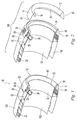
- Figures 6 and 7 show one possible arrangement for the ice protection electrical heaters 70a, 70b, 70c, and 72.
- one or more parting strip heaters 72 are provided along an inner surface of the leading edge 12 of the removable cowling 40.
- each parting strip heater 72 is positioned to be substantially coincident with an airflow stagnation line along the engine inlet's leading edge 12.
- a plurality of shed zone heaters 70a, 70b, 70c are provided in substantially side by side relation along the inside surface of the leading edge 12, thereby substantially covering the entire inside surface of the leading edge 12.
- adjacent shed zone heaters may abut one another if they are electrically isolated from each other, more preferably, they are spaced apart from one another by a gap of between about 0.04" to about 0.5"; other gap spacings may also be employed.
- power can be supplied substantially constantly to the parting strip heater(s) 72 to provide more or less continuous ice protection along the airflow stagnation line.
- Power also can be intermittently supplied to the shed zone heaters 70a, 70b, and 70c to shed accumulated ice on either side of the stagnation line.
- pulses of electrical power may be supplied in sequence to shed zone heaters 70a, to shed zone heaters 70b, to shed zone heaters 70c, again to shed zone heaters 70a, etc.
- the distribution of electric power to the various heaters 70a, 70b, 70c, and 72 is controlled by one or more electrical supply control boxes 26. This cyclic rationing of electric power between the various shed zone heaters 70a, 70b, 70c acts to minimize the amount of electric power that must be derived from an aircraft's finite electrical generation capacity, while effectively providing ice protection to the engine inlet's leading edge 12.
- all shed zone heaters designated 70a are active for a first period of time, then all shed zone heaters designated 70b are active for a second period of time and finally all shed zone heater designated 70c are active during a third period of time. It is further understood that these three periods of time need not necessarily be of equal duration and that they need not necessarily be contiguous- i.e., there may be some intervening periods during which none of these three sets of shed zone heaters is on. It is also understood that other numbers of sets of heaters may be provided - for instance, two sets, four sets, or five sets, etc.
- Figure 8 shows one possible arrangement for installing the heaters 70a, 70b, 70c, 72 on the inner surface of the inlet cowling 40.
- a parting strip heater 72 is mounted on the inner surface of the lip cowling 40 proximate to the underside of the airflow stagnation line at the leading edge 12.
- a plurality of shed zone heating pads 70a, 70b, 70c are applied over the parting strip heater 72 such that the heater pads 70a, 70b, 70c cover substantial portions of the inside surface of the leading edge 12 on each side of the parting strip heater 72.
- the heaters 70a, 70b, 70c, 72 may be any type of substantially flat, foil, or ribbon heater capable of supplying sufficient heat energy to the cowling 40 to effectively de-ice the cowling 40 while in service.
- the heating elements 70a, 70b, 70c, 72 may be configured as "ribbons", i.e. interconnected conductive sections, that are mounted on a flexible backing.
- the low-power electric heaters 70a, 70b, 70c, 72 may be like the ice protection electrical heaters described in U.S. Patent No. 5,475,204 , assigned to Goodrich Corporation.
- the ice protection electrical heaters 70a, 70b, 70c, 72 may be like those described in U.S. Patent Application Serial No. 10/840,736 , filed on May 6, 2004.
- the disclosures of U.S. Patent No. 5,475,204 and U.S. Patent Application Serial No. 10/840,736 are hereby incorporated by reference in their entireties.
- adjacent portions of the inlet cowling may be sequentially heated by alternatingly supplying current to the plurality of electrical ribbon heaters.
- Suitable electric wiring 74 supplies electric power to the ice protection electrical heaters 70a, 70b, 70c, 72 from one or more heater switch boxes 28.
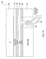
- Figure 9a shows a cross-section of an inlet cowling 40a in which the ice protection electrical heater is spaced apart from the ice 950 by one or more layers.
- the structural skin 904 of the cowling 40a provides support for the layers above. These layers include a first insulation layer 906, a heater layer 908 atop the first insulation layer, a second insulation layer 910 atop the heater layer 908, and an erosion shield 912 atop the second insulation layer 910. Heat from the heater layer 908 passes through the second insulation layer 910 and the erosion shield to melt the ice 950.
- the thickness of the inlet cowling is on the order of 0.1" - 0.2".
- the structural skin 904 is formed of a metallic or composite material having a thickness between about 0.02" and 0.10";
- the first insulation layer 906 is formed of an electrically inert (i.e., electrically insulative) material having a thickness between about 0.01" and 0.04";
- the heater layer 908 comprises electrical heaters formed of a metallic or conductive material on a nonconductive plastic film or other substrate and having a thickness between about 0.005" and 0.020";
- the second insulation layer 910 is formed of an electrically inert (i.e., electrically insulative) but thermally conductive material having a thickness between about 0.01" and 0.04";
- the erosion shield 912 comprises a thermally conductive metallic skin or coating having a thickness between about 0.002" and 0.020".
- the ice protection electrical heaters 908 may be mounted on the outer surface. When positioned on the outer surface, the ice protection electrical heaters are more directly exposed to the ice and so the energy efficiency of the system may improve. Through holes may be formed in some of the underlying layers of the cowling 40 at spaced apart intervals to accommodate wires and other connections to deliver current to the ice protection electrical heaters.
- Figure 9b shows a cross-section of an inlet cowling 40b in which the heater forms the outer surface of the cowling 40b. Again, the structural skin 924 of the cowling 40b provides support for the layers above.
- These layers include a first insulation layer 926, and a heater layer 928 atop the first insulation layer 924, all having substantially the same composition and thickness ranges discussed above with respect to Fig. 9a. In this instance, however, the heater layer 928 is exposed to the elements and so must also serve as the erosion shield.
- a wire or cable 930 provides current to the heater layers 908, 928.
- the wire is connected to the heater via an electrical solder connection 932, as seen in these figures. It is understood in these figures that each of the heater layers may comprise multiple individual ice protection electrical heaters.
- Engine inlets in accordance with the present invention may realize efficient ice protection with lower weight inlet structure, as compared to a conventional hot air thermal anti-ice (TAI) system. Furthermore, eliminating the pressures and temperatures associated with a traditional TAI system simplifies certain aspects of nacelle design. For instance, traditional split lines between the inlet major components are driven by the thermal anti-ice system and the acoustic requirements. The electrical system of the present invention generally does not rely upon these limitations and may therefore allow for these locations to be optimized for other design criteria. As an example, moving the traditional split line between the inlet lip and the outer barrel aft improves the aerodynamic performance of the inlet and allows the lip to be incorporated into a design that promotes natural laminar flow while also covering an access opening.
- TAI hot air thermal anti-ice
Landscapes
- Engineering & Computer Science (AREA)
- Chemical & Material Sciences (AREA)
- Combustion & Propulsion (AREA)
- Aviation & Aerospace Engineering (AREA)
- Mechanical Engineering (AREA)
- General Engineering & Computer Science (AREA)
- Wind Motors (AREA)
- Structures Of Non-Positive Displacement Pumps (AREA)
Abstract
Description
- This application is related to
U.S. Patent Application No. 11/111,834 - The invention relates to ice protection systems for aircraft, and more specifically relates to an aircraft equipped with a low power high efficiency electrical ice protection system.
- The accumulation of ice on aircraft wings and other structural members in flight is a danger that is well known. Such "structural members" include any aircraft surface susceptible to icing during flight, including wings, stabilizers, rotors, and so forth. Ice accumulation on aircraft engine nacelle inlets also can be problematic. Attempts have been made since the earliest days of flight to overcome the problem of ice accumulation. While a variety of techniques have been proposed for removing ice from aircraft during flight, these techniques have had various drawbacks that have stimulated continued research activities. One approach that has been used is so-called thermal ice protection. In thermal ice protection, the leading edges, that is, the portions of the aircraft that meet and break the airstream impinging on the aircraft, are heated to prevent the formation of ice or to loosen accumulated ice. The loosened ice is blown from the structural members by the airstream passing over the aircraft.
- In one form of thermal ice protection, heating is accomplished by placing an electrothermal pad(s), including heating elements, over the leading edges of the aircraft, or by incorporating the heating elements into the structural members of the aircraft. Electrical energy for each heating element is derived from a generating source driven by one or more of the aircraft engines. The electrical energy is intermittently or continuously supplied to provide heat sufficient to prevent the formation of ice or to loosen accumulating ice.
- With some commonly employed thermal ice protection systems, the heating elements may be configured as ribbons, i.e. interconnected conductive segments that are mounted on a flexible backing. When applied to a wing or other airfoil surface, the segments are arranged in strips or zones extending spanwise or chordwise along the aircraft wing or airfoil. When applied to the engine inlet the heating elements can be applied either in the circumferential or radial orientation. One of these strips, known as a spanwise parting strip, is disposed along a spanwise axis which commonly coincides with a stagnation line that develops during flight. Other strips, known as chordwise parting strips, are disposed at the ends of the spanwise parting strip and are aligned along chordwise axes. Other zones, known as spanwise shedding zones, typically are positioned on either side of the spanwise parting strip at a location intermediate the chordwise parting strips.
- In one preferred form of ice protection, an electrical current is transmitted continuously through the parting strips so that the parting strips are heated continuously to a temperature above 32 degrees Fahrenheit. In the spanwise shedding zones, on the other hand, current is transmitted intermittently so that the spanwise shedding zones are heated intermittently to a temperature above about 32 degrees Fahrenheit.
- One problem associated with providing such electrothermal ice protection systems on the nacelle inlets of aircraft engines involves providing sufficient numbers of access openings in the inner or outer barrels of the engine inlet for accessing and servicing the heating equipment such as heater elements and associated components. Providing such access openings proximate to the leading edge of the nacelle inlet can create non-smooth interruptions or protuberances along the otherwise smooth aerodynamic surface of the engine inlet. These interruptions or protuberances can interfere with the desired natural laminar airflow into and around the engine inlets, and may contribute to the creation of unwanted noise and drag.
- Therefore, there is a need for a thermal ice protection system for the nacelle inlet of an aircraft engine that provides effective ice protection action, that includes a plurality of conveniently positioned service access openings for use in servicing and maintaining the ice protection system components, and that maintains a smooth aerodynamic inlet shape that results in substantially natural laminar airflow along the critical surfaces of the inlet.
- In one aspect, the present invention is directed to an electric ice protection system for an aircraft engine nacelle having an inner barrel and an outer barrel. The ice protection system comprises an engine inlet cowling having an outer lip configured for engagement with at least a portion of the outer barrel, an inner lip configured for engagement with at least a portion of the inner barrel, and a leading edge extending between the outer and inner lips; at least one parting strip electrical heater attached to the cowling proximate to the leading edge; and a plurality of shed zone electrical heaters arranged side by side on either side of the parting strip electrical heater.
- In another aspect, the present invention is directed to an aircraft engine nacelle comprising an inner support comprising an outer barrel portion, an inner barrel portion, and a forward wall connecting the outer and inner barrel portions; and a removable inlet cowling attachable to the inner support, the removable inlet cowling having an outer lip, an inner lip, and a leading edge extending between the outer and inner lips, and at least one ice protection electrical heater associated with the leading edge portion of the removable inlet cowling.
- In yet another aspect, the present invention is directed to an aircraft engine nacelle heater assembly for an aircraft engine nacelle having an inner barrel, an outer barrel, a forward wall connecting the inner and outer barrels, and a first electrical connector on the forward wall. The heater assembly comprises an inlet cowling removably connectable to an aircraft engine nacelle and configured to cover at least a portion of the inner barrel and at least a portion of the outer barrel, when connected to said aircraft engine nacelle; and at least one ice protection electrical heater associated with the inlet cowling, the ice protection electrical heater including a second electrical connector; wherein the second electrical connector is configured to connect to the first electrical connector, when the inlet cowling covers the inner and outer barrel portions.
- In still another aspect, the present invention is directed to a method of preventing ice accumulation on an aircraft engine nacelle inlet having an airflow stagnation line therealong. The method comprises continuously heating the aircraft engine nacelle inlet along a stagnation line that extends at least partly along a circumference of said aircraft engine nacelle inlet; and sequentially heating the aircraft engine nacelle inlet within spaced zones on each side of the stagnation line so as to prevent ice buildup on the aircraft engine inlet.
-
- Figure 1 is a perspective view of a portion of an aircraft engine having a nacelle inlet thermal ice protection system according to the invention;
- Figure 2 is a perspective view of the aircraft engine of Figure 1 with the inlet cowling detached;
- Figure 3 is an enlarged perspective view of a forward portion of the aircraft engine of Figures 1 and 2;
- Figure 4 is a cross-sectional view of a nacelle inlet for an aircraft engine according to the invention;
- Figure 5 is an exploded cross-sectional view of the nacelle inlet of Figure 4 with the inlet cowling detached;
- Figure 6 is a rear perspective view of a portion of an aircraft engine showing an ice protection electrical heater arrangement on the inner surface of an inlet cowling;
- Figure 7 is a front perspective view an inlet cowling showing the ice protection electrical heater arrangement of Figure 6;
- Figure 8 is a rear perspective view of the inlet cowling of Figure 7 showing placement of ice protection electrical heaters on an inner surface of the inlet;
- Figure 9a shows a cross-sectional view of a cowling in which the heater is part of an inner layer of the cowling; and
- Figure 9b shows a cross-sectional view of a cowling in which the heater is part of an outer layer of the cowling.
- Figure 1 shows a portion of an
aircraft engine nacelle 100 equipped with one embodiment of a nacelle inlet thermalice protection assembly 10 according to the invention. Theengine nacelle 100 includes a substantially cylindricalinner barrel 102 and a concentricouter barrel 104. Thenacelle inlet assembly 10 is disposed on the forward edges of the engine's nacelle inner andouter barrels nacelle inlet assembly 10 has a smooth aerodynamic shape that substantially promotes natural laminar airflow along the forwardmost surfaces of theengine nacelle 100.
As shown in Figure 2, thenacelle inlet assembly 10 includes a removable inlet cowling 40. The inlet cowling 40 includes aninner lip 16, anouter lip 14, and a leadingedge portion 12 connecting the two. Theaft edge 18 of theouter lip 14 mates with thenacelle inlet assembly 10 along asplit line 60. Theaft edge 18 andsplit line 60 are positioned a substantial distance downstream of the leadingedge portion 12, thereby providing a smooth, aerodynamic surface on theouter lip 14 between the leadingedge 12 and thesplit line 60. The lip cowling 40 may be a single continuous 360° airfoil that covers an entire engine inlet, or may comprise a plurality of separable, arcuate cowling segments placed in a circumferential arrangement. In one embodiment, the separable cowling segments have airfoil cross-sections that are placed side by side in a circumferential arrangement. - As shown in Figures 2 and 3, the
nacelle inlet assembly 10 further includes aforward support 30. Thesupport 30 may be substantially permanently connected to the inner andouter barrels aircraft engine nacelle 100, or may be integrally constructed therewith. Theforward support 30 provides strength and rigidity to thenacelle inlet assembly 10. As shown in Figure 3, theforward support 30 includes aninner barrel portion 32, anouter barrel portion 36 and aforward wall portion 34 connecting the inner and outer barrel portions. Theforward support 30 may house a plurality of spaced ice protection electricalheater switch boxes 28 for relaying electric power to the ice protection system's heaters, which are described in detail below. As shown in Figure 6, electric power from a pylonelectrical junction box 20 may be supplied to one ormore control boxes 26 viapower feeder harness 24, and may be supplied from thecontrol box 26 to theheater switch boxes 28 viapower supply harnesses 27. - As shown in Figures 2 and 3, the
outer barrel portion 36 of theforward support 30 includes a plurality of circumferentially spacedservice access openings 38 therethrough. Each of theservice access openings 38 is located proximate to one or more associatedheater switch boxes 28, and provides access to at least one of theheater switch boxes 28 from outside theouter barrel portion 36. - As shown in Figures 1 and 4, when the
inlet cowling 40 is installed on theforward support 30, theouter lip 14 covers each of the respectiveservice access openings 38 in theouter barrel portion 36 of theforward support 30. Therefore, this arrangement precludes the need for an individual cover for each service access opening 38. This arrangement also provides a continuous smoothaerodynamic lip surface 14 proximate to the leadingedge 12 that helps promote natural laminar airflow across the nacelle during flight. - As shown in Figures 1, 2 and 3, the
inlet cowling 40 is connected to theforward support 30 along both aft edges 18, 19 by pluralities of suitableremovable fasteners 50. For example, thefasteners 50 may include bolts, rivets, or other suitable fasteners having substantially flush profiles. Preferably, the fasteners are of a type that is easily installed and removed by service personnel. - Further details of the
nacelle inlet assembly 10 are shown in Figures 4 and 5. As shown in Figure 4, theinlet cowling 40 substantially conforms to the shape of theforward support 30 except for a ice protectionelectrical heater pocket 80 formed between theleading edge 12 of thecowling 40 and theforward wall 34 of theforward support 30. Thepocket 80 provides space for a plurality of iceprotection ribbon heaters edge 12 of theinlet cowling 40, as well as for anelectrical connector 76 which connects toelectrical connector 74 mounted on theforward wall 34. - The first and second
electrical connectors inlet cowling 40 is adjusted from a first position in which it is separated from the inner and outer barrel portions to a second position in which it covers the inner and outer barrel portions. Alternatively,connectors heaters heater switch boxes 28 viaheater supply harness 29 andelectrical connectors 74. In the embodiment shown, theelectrical connectors 74 are mounted on theforward wall 34 of theforward support 30. - As shown in Figure 4, the
inner barrel portion 32 of theforward support 30 may include anacoustic portion 33, known to those skilled in the act, for attenuating engine noise. In the arrangement shown, theaft edge 19 of theinner lip 16 adjoins theforward support 30 at a position that is immediately forward (or upstream of) of theacoustic portion 33. - Figures 4 and 5 show the maintenance and service access features of the
nacelle inlet assembly 10. With theinlet cowling 40 removed, theservice access openings 38 are uncovered, and various ice protection electrical heating equipment such as theheater switch boxes 28, heater supply harnesses 29, power supply harnesses 27, andelectrical connectors 74 can be easily accessed by service personnel extending his or herhand 150 through theservice access openings 38. In addition, the removedinlet cowling 40 provides ready access to the ice protectionelectrical heaters electrical connectors 76 mounted on the inside surfaces of thecowling 40. If required, theremovable inlet cowling 40 can be easily replaced with asecond inlet cowling 40, and can be separated from an associatedengine nacelle 100 for remote service or repair. - Figures 6 and 7 show one possible arrangement for the ice protection
electrical heaters parting strip heaters 72 are provided along an inner surface of the leadingedge 12 of theremovable cowling 40. Preferably, eachparting strip heater 72 is positioned to be substantially coincident with an airflow stagnation line along the engine inlet's leadingedge 12. Second, a plurality of shedzone heaters edge 12, thereby substantially covering the entire inside surface of the leadingedge 12. Although adjacent shed zone heaters may abut one another if they are electrically isolated from each other, more preferably, they are spaced apart from one another by a gap of between about 0.04" to about 0.5"; other gap spacings may also be employed. In this arrangement, power can be supplied substantially constantly to the parting strip heater(s) 72 to provide more or less continuous ice protection along the airflow stagnation line. - Power also can be intermittently supplied to the shed
zone heaters zone heaters 70a, to shedzone heaters 70b, to shedzone heaters 70c, again to shedzone heaters 70a, etc. The distribution of electric power to thevarious heaters supply control boxes 26. This cyclic rationing of electric power between the various shedzone heaters edge 12. - It is understood that one may operate the heating system such that all shed zone heaters designated 70a are active for a first period of time, then all shed zone heaters designated 70b are active for a second period of time and finally all shed zone heater designated 70c are active during a third period of time. It is further understood that these three periods of time need not necessarily be of equal duration and that they need not necessarily be contiguous- i.e., there may be some intervening periods during which none of these three sets of shed zone heaters is on. It is also understood that other numbers of sets of heaters may be provided - for instance, two sets, four sets, or five sets, etc.
- Figure 8 shows one possible arrangement for installing the
heaters inlet cowling 40. In this arrangement, aparting strip heater 72 is mounted on the inner surface of thelip cowling 40 proximate to the underside of the airflow stagnation line at theleading edge 12. Next, a plurality of shedzone heating pads parting strip heater 72 such that theheater pads edge 12 on each side of theparting strip heater 72. Theheaters cowling 40 to effectively de-ice thecowling 40 while in service. Theheating elements electric heaters U.S. Patent No. 5,475,204 , assigned to Goodrich Corporation. Alternatively, the ice protectionelectrical heaters U.S. Patent Application Serial No. 10/840,736 , filed on May 6, 2004. The disclosures ofU.S. Patent No. 5,475,204 andU.S. Patent Application Serial No. 10/840,736 are hereby incorporated by reference in their entireties. And so, when in use, adjacent portions of the inlet cowling may be sequentially heated by alternatingly supplying current to the plurality of electrical ribbon heaters. Suitableelectric wiring 74 supplies electric power to the ice protectionelectrical heaters heater switch boxes 28. - Figure 9a shows a cross-section of an
inlet cowling 40a in which the ice protection electrical heater is spaced apart from theice 950 by one or more layers. Thestructural skin 904 of thecowling 40a provides support for the layers above. These layers include afirst insulation layer 906, aheater layer 908 atop the first insulation layer, asecond insulation layer 910 atop theheater layer 908, and anerosion shield 912 atop thesecond insulation layer 910. Heat from theheater layer 908 passes through thesecond insulation layer 910 and the erosion shield to melt theice 950. - In one embodiment, the thickness of the inlet cowling is on the order of 0.1" - 0.2". The
structural skin 904 is formed of a metallic or composite material having a thickness between about 0.02" and 0.10"; thefirst insulation layer 906 is formed of an electrically inert (i.e., electrically insulative) material having a thickness between about 0.01" and 0.04"; theheater layer 908 comprises electrical heaters formed of a metallic or conductive material on a nonconductive plastic film or other substrate and having a thickness between about 0.005" and 0.020"; thesecond insulation layer 910 is formed of an electrically inert (i.e., electrically insulative) but thermally conductive material having a thickness between about 0.01" and 0.04"; and theerosion shield 912 comprises a thermally conductive metallic skin or coating having a thickness between about 0.002" and 0.020". - Instead of being mounted on the inner surface of the
inlet cowling 40 as shown in Figs. 4-6, the ice protectionelectrical heaters 908 may be mounted on the outer surface. When positioned on the outer surface, the ice protection electrical heaters are more directly exposed to the ice and so the energy efficiency of the system may improve. Through holes may be formed in some of the underlying layers of thecowling 40 at spaced apart intervals to accommodate wires and other connections to deliver current to the ice protection electrical heaters. Figure 9b shows a cross-section of aninlet cowling 40b in which the heater forms the outer surface of thecowling 40b. Again, thestructural skin 924 of thecowling 40b provides support for the layers above. These layers include afirst insulation layer 926, and aheater layer 928 atop thefirst insulation layer 924, all having substantially the same composition and thickness ranges discussed above with respect to Fig. 9a. In this instance, however, theheater layer 928 is exposed to the elements and so must also serve as the erosion shield. - In both Figs. 9a and 9b, a wire or
cable 930 provides current to the heater layers 908, 928. preferably, the wire is connected to the heater via anelectrical solder connection 932, as seen in these figures. It is understood in these figures that each of the heater layers may comprise multiple individual ice protection electrical heaters. - Engine inlets in accordance with the present invention may realize efficient ice protection with lower weight inlet structure, as compared to a conventional hot air thermal anti-ice (TAI) system. Furthermore, eliminating the pressures and temperatures associated with a traditional TAI system simplifies certain aspects of nacelle design. For instance, traditional split lines between the inlet major components are driven by the thermal anti-ice system and the acoustic requirements. The electrical system of the present invention generally does not rely upon these limitations and may therefore allow for these locations to be optimized for other design criteria. As an example, moving the traditional split line between the inlet lip and the outer barrel aft improves the aerodynamic performance of the inlet and allows the lip to be incorporated into a design that promotes natural laminar flow while also covering an access opening.
- The above description of various embodiments of the invention is intended to describe and illustrate various aspects of the invention, and is not intended to limit the invention thereto. Persons of ordinary skill in the art will understand that certain modifications may be made to the described embodiments without departing from the invention. All such modifications are intended to be within the scope of the appended claims.
Claims (20)
- An electric ice protection system for an aircraft engine nacelle having an inner barrel and an outer barrel, the ice protection system comprising:an engine inlet cowling having an outer lip configured for engagement with at least a portion of the outer barrel, an inner lip configured for engagement with at least a portion of the inner barrel, and a leading edge extending between the outer and inner lips;at least one parting strip electrical heater attached to the cowling proximate to the leading edge; anda plurality of shed zone electrical heaters arranged side by side on either side of the parting strip electrical heater.
- The electric ice protection system according to claim 1, further comprising:at least one heater controller configured to selectively supply pulses of electrical power to the shed zone electrical heaters.
- The electric ice protection system according to claim 1, wherein an axial length of the outer lip is greater than an axial length of the inner lip.
- The low power electric ice protection system according to claim 1, wherein the cowling comprises a plurality of cowling segments placed in a circumferential arrangement.
- The electric ice protection system according to claim 1, wherein the cowling is removably connectable to the inner and outer barrels.
- The electric ice protection system according to claim 1, wherein the at least one parting strip electrical heater, and the plurality of shed zone electrical heaters are arranged on an inner surface of the cowling.
- The electric ice protection system according to claim 1, wherein the at least one parting strip electrical heater, and the plurality of shed zone electrical heaters are arranged on an outer surface of the cowling.
- The electric ice protection system according to claim 1, wherein the cowling has an aerodynamic profile that promotes laminar airflow across the outer lip.
- An aircraft engine nacelle comprising:an inner support comprising an outer barrel portion, an inner barrel portion, and a forward wall extending between the outer and inner barrel portions; anda removable inlet cowling attachable to the inner support, the removable inlet cowling having an outer lip, an inner lip, and a leading edge extending between the outer and inner lips, and at least one ice protection electrical heater associated with the leading edge of the removable inlet cowling.
- The aircraft engine nacelle according to claim 9, wherein the inlet cowling is configured to cover at least a portion of the outer barrel portion and at least a portion of the inner barrel portion.
- The aircraft engine nacelle according to claim 9, wherein the inner barrel portion comprises an acoustic insulation material.
- The aircraft engine nacelle according to claim 9, further comprising:at least one heater switch box located between the inner barrel portion and the outer barrel portion.
- An aircraft engine nacelle according to claim 9, wherein the inlet cowling is removably connected to the inner support.
- The aircraft engine nacelle according to claim 9, wherein the forward wall of the inner support and the leading edge of the inlet cowling define a space therebetween.
- The aircraft engine nacelle according to claim 14, further comprising:a first electrical connector associated with the inner support and a second electrical connector associated with the inlet cowling, and whereinattaching the inlet cowling to the inner support automatically causes the first and second electrical connectors to form an electrical connection within said space.
- An aircraft engine nacelle heater assembly for an aircraft engine nacelle having an inner barrel, an outer barrel, a forward wall extending between the inner and outer barrels, and a first electrical connector on the forward wall, the heater assembly comprising:an inlet cowling removably connectable to an aircraft engine nacelle and configured to cover at least a portion of the inner barrel and at least a portion of the outer barrel, when connected to said aircraft engine nacelle; andat least one ice protection electrical heater associated with the inlet cowling, the ice protection electrical heater including a second electrical connector;wherein the second electrical connector is configured to connect to the first electrical connector, when the inlet cowling covers the inner and outer barrel portions.
- The aircraft engine nacelle heater assembly according to claim 16, wherein the inlet cowling and the forward wall define therebetween an interior space, when the inlet cowling covers the inner and outer barrel portions.
- The aircraft engine nacelle heater assembly according to claim 17, wherein the first and second electrical connectors automatically connect to one another, when the inlet cowling is adjusted from a first position in which it is separated from the inner and outer barrel portions to a second position in which it covers the inner and outer barrel portions.
- A method of preventing ice accumulation on an aircraft engine nacelle inlet having an airflow stagnation line therealong, the method comprising:continuously heating the aircraft engine nacelle inlet along a stagnation line that extends at least partly along a circumference of said aircraft engine nacelle inlet; andsequentially heating the aircraft engine nacelle inlet within spaced zones on each side of the stagnation line so as to prevent ice buildup on the aircraft engine inlet.
- The method according to claim 19, comprising alternatingly supplying current to a plurality of ribbon heaters in said spaced zones.
Applications Claiming Priority (1)
| Application Number | Priority Date | Filing Date | Title |
|---|---|---|---|
| US11/111,835 US7513458B2 (en) | 2005-04-22 | 2005-04-22 | Aircraft engine nacelle inlet having electrical ice protection system |
Publications (2)
| Publication Number | Publication Date |
|---|---|
| EP1715160A1 true EP1715160A1 (en) | 2006-10-25 |
| EP1715160B1 EP1715160B1 (en) | 2009-08-12 |
Family
ID=36127301
Family Applications (1)
| Application Number | Title | Priority Date | Filing Date |
|---|---|---|---|
| EP06005410A Expired - Lifetime EP1715160B1 (en) | 2005-04-22 | 2006-03-16 | Aircraft engine nacelle inlet having electrical ice protection system |
Country Status (4)
| Country | Link |
|---|---|
| US (1) | US7513458B2 (en) |
| EP (1) | EP1715160B1 (en) |
| AT (1) | ATE439511T1 (en) |
| DE (1) | DE602006008374D1 (en) |
Cited By (12)
| Publication number | Priority date | Publication date | Assignee | Title |
|---|---|---|---|---|
| FR2898869A1 (en) * | 2006-03-24 | 2007-09-28 | Aircelle Sa | ELECTRIC DEGIVER NACELLE AIR INLET LAUNDRY |
| FR2908738A1 (en) * | 2006-11-16 | 2008-05-23 | Airbus France Sas | AIRCRAFT ATTACK RIDGE. |
| EP1935783A1 (en) * | 2006-12-19 | 2008-06-25 | Honeywell International Inc. | Ice protection system including a plurality of segmented sub-areas and a cyclic diverter valve |
| FR2927061A1 (en) * | 2008-02-01 | 2009-08-07 | Aircelle Sa | LOCKING SYSTEM FOR AIR INTAKE STRUCTURE OF A TURBOJET NACELLE |
| WO2011127995A1 (en) * | 2010-04-12 | 2011-10-20 | Siemens Aktiengesellschaft | Fixation of a heating mat to a blade of a wind turbine |
| EP2110314A3 (en) * | 2008-04-16 | 2012-12-12 | United Technologies Corporation | De-icing system for engine inlet and method of preventing ice formation |
| WO2014170609A1 (en) * | 2013-04-19 | 2014-10-23 | Aircelle | Nacelle for an aircraft turbojet engine with an extended front lip |
| EP2069624B1 (en) * | 2006-10-02 | 2016-04-20 | Aircelle | Removable air intake structure for turbojet engine nacelle |
| FR3050176A1 (en) * | 2016-04-15 | 2017-10-20 | Snecma | NACELLE FOR PROPULSIVE ASSEMBLY |
| FR3060651A1 (en) * | 2016-12-20 | 2018-06-22 | Airbus Operations | AIR INTAKE STRUCTURE FOR AN AIRCRAFT NACELLE |
| EP3501989A1 (en) * | 2017-12-21 | 2019-06-26 | The Boeing Company | Integrated lightning protection and electrical de-icing for aerodynamic structures |
| EP3747775A1 (en) * | 2019-06-04 | 2020-12-09 | Rohr, Inc. | Nacelle with a translatable inlet for an aircraft propulsion system |
Families Citing this family (24)
| Publication number | Priority date | Publication date | Assignee | Title |
|---|---|---|---|---|
| ES2341794T3 (en) * | 2005-08-25 | 2010-06-28 | Gkn Aerospace Services Limited | AUXILIARY WING OF THE WING ATTACK OF THE WING OF AN AIRPLANE. |
| DE102006050534B4 (en) * | 2006-10-26 | 2013-12-12 | Airbus Operations Gmbh | Conduit system for an aircraft, in particular an aircraft |
| US8006934B2 (en) * | 2008-03-31 | 2011-08-30 | United Technologies Corporation | Heating architecture for a composite fairing |
| US20100123044A1 (en) * | 2008-11-17 | 2010-05-20 | Botura Galdemir C | Aircraft Ice Protection System |
| US20110233340A1 (en) * | 2010-03-29 | 2011-09-29 | Christy Daniel P | Aircraft ice protection system |
| US8746622B2 (en) * | 2010-06-08 | 2014-06-10 | Textron Innovations Inc. | Aircraft de-icing system and method |
| US8919494B2 (en) | 2012-07-31 | 2014-12-30 | Rohr, Inc. | Electric heater for integration into an aircraft acoustic panel |
| US9627874B2 (en) * | 2012-09-12 | 2017-04-18 | Unison Industries, Llc | Mounting device and method of assembling the same |
| GB201306674D0 (en) * | 2013-04-12 | 2013-05-29 | Rolls Royce Plc | Rigid Raft for a Gas Turbine Engine |
| US10662877B2 (en) * | 2016-10-03 | 2020-05-26 | Rohr, Inc. | Embedded aircraft heater repair |
| US10655539B2 (en) * | 2017-10-16 | 2020-05-19 | Rolls-Royce North America Technologies Inc. | Aircraft anti-icing system |
| DE102017125763A1 (en) * | 2017-11-03 | 2019-05-09 | Airbus Operations Gmbh | Method for producing an aircraft fuselage |
| FR3079818A1 (en) * | 2018-04-10 | 2019-10-11 | Airbus Operations (S.A.S.) | AIRCRAFT ENGINE NACELLE WITH A FROST PROTECTIVE SYSTEM AND METHOD FOR PROTECTING THE SAME |
| US20190360399A1 (en) * | 2018-05-25 | 2019-11-28 | Rolls-Royce Corporation | System and method to promote early and differential ice shedding |
| EP4305653A1 (en) | 2021-03-12 | 2024-01-17 | Essex Industries, Inc. | Rocker switch |
| EP4309200A1 (en) | 2021-03-15 | 2024-01-24 | Essex Industries, Inc. | Five-position switch |
| FR3126964B1 (en) * | 2021-09-13 | 2023-08-04 | Safran Nacelles | Nacelle for an aircraft propulsion system comprising an access space closed off by a cowling with tangential clamping |
| US11975847B2 (en) | 2022-03-16 | 2024-05-07 | General Electric Company | Ice protection systems for aircraft |
| CN116696550A (en) * | 2023-07-14 | 2023-09-05 | 中国航发沈阳发动机研究所 | Aeroengine air inlet casing fairing |
| US12600487B2 (en) | 2023-08-08 | 2026-04-14 | Rohr, Inc. | Segmented nacelle inlet lip with electric anti-icing system |
| US12326113B2 (en) | 2023-08-08 | 2025-06-10 | Rohr, Inc. | Segmented nacelle inlet lip with electric anti-icing system |
| US12296971B2 (en) | 2023-08-08 | 2025-05-13 | Rohr, Inc. | Segmented nacelle inlet lip with electric anti-icing system |
| US12280884B2 (en) | 2023-08-08 | 2025-04-22 | Rohr, Inc. | Outer barrel support structure for nacelle inlet structure |
| US12365466B1 (en) | 2024-01-23 | 2025-07-22 | General Electric Company | Power switching system of an anti-ice system for use with a main power supply and an auxiliary power supply |
Citations (8)
| Publication number | Priority date | Publication date | Assignee | Title |
|---|---|---|---|---|
| GB1247071A (en) * | 1969-01-24 | 1971-09-22 | Rolls Royce | An aircraft engine nose cowl |
| GB1314162A (en) * | 1969-05-08 | 1973-04-18 | Secr Defence | Intake anti-icing system for gas turbine engines |
| GB2259287A (en) * | 1991-09-04 | 1993-03-10 | Rolls Royce Plc | Apparatus for and method of de-icing a surface |
| EP0680878A1 (en) * | 1994-04-13 | 1995-11-08 | The B.F. Goodrich Company | Electrothermal deicing system |
| US5475204A (en) | 1990-06-01 | 1995-12-12 | The B. F. Goodrich Company | Electrical heater de-icer |
| US6227492B1 (en) * | 1999-08-06 | 2001-05-08 | Bell Helicopter Textron Inc. | Redundant ice management system for aircraft |
| US6328258B1 (en) * | 1998-12-21 | 2001-12-11 | Aerospatial Natra | Air intake structure for aircraft engine |
| US20070075188A1 (en) | 2004-05-06 | 2007-04-05 | Paul Stoner | Low power, pulsed, electro-thermal ice protection system |
Family Cites Families (15)
| Publication number | Priority date | Publication date | Assignee | Title |
|---|---|---|---|---|
| US3397302A (en) * | 1965-12-06 | 1968-08-13 | Harry W. Hosford | Flexible sheet-like electric heater |
| GB1117843A (en) | 1966-02-25 | 1968-06-26 | Rolls Royce | Improvements relating to anti-icing heating apparatus |
| DE2443224C3 (en) * | 1974-09-10 | 1979-02-22 | Licentia Patent-Verwaltungs-Gmbh, 6000 Frankfurt | Process for deicing engine, wing and tail unit systems on missiles |
| AT383931B (en) * | 1982-11-11 | 1987-09-10 | Hans Oppitz | SURFACE HEATING ELEMENT, IN PARTICULAR FOR COVERING OR HEATING CEILINGS |
| US4826108A (en) * | 1987-07-16 | 1989-05-02 | The B. F. Goodrich Company | De-icer |
| US5098037A (en) * | 1989-11-06 | 1992-03-24 | The B. F. Goodrich Company | Structural airfoil having integral expulsive system |
| US5248116A (en) * | 1992-02-07 | 1993-09-28 | The B. F. Goodrich Company | Airfoil with integral de-icer using overlapped tubes |
| US5361183A (en) * | 1993-06-30 | 1994-11-01 | Alliedsignal Inc. | Ground fault protection for electrothermal de-icing applications |
| US5427332A (en) * | 1993-11-10 | 1995-06-27 | The B. F. Goodrich Company | Modular ice protection assembly |
| US5657951A (en) * | 1995-06-23 | 1997-08-19 | The B.F. Goodrich Company | Electrothermal de-icing system |
| US6027075A (en) * | 1997-06-16 | 2000-02-22 | Trustees Of Dartmouth College | Systems and methods for modifying ice adhesion strength |
| US6279856B1 (en) * | 1997-09-22 | 2001-08-28 | Northcoast Technologies | Aircraft de-icing system |
| US6237874B1 (en) * | 1997-09-22 | 2001-05-29 | Northcoast Technologies | Zoned aircraft de-icing system and method |
| US6725542B1 (en) * | 1999-09-17 | 2004-04-27 | Alan R Maguire | Method of assembling a gas turbine engine and nacelle |
| US7588212B2 (en) * | 2003-07-08 | 2009-09-15 | Rohr Inc. | Method and apparatus for noise abatement and ice protection of an aircraft engine nacelle inlet lip |
-
2005
- 2005-04-22 US US11/111,835 patent/US7513458B2/en not_active Expired - Fee Related
-
2006
- 2006-03-16 EP EP06005410A patent/EP1715160B1/en not_active Expired - Lifetime
- 2006-03-16 DE DE602006008374T patent/DE602006008374D1/en not_active Expired - Lifetime
- 2006-03-16 AT AT06005410T patent/ATE439511T1/en not_active IP Right Cessation
Patent Citations (8)
| Publication number | Priority date | Publication date | Assignee | Title |
|---|---|---|---|---|
| GB1247071A (en) * | 1969-01-24 | 1971-09-22 | Rolls Royce | An aircraft engine nose cowl |
| GB1314162A (en) * | 1969-05-08 | 1973-04-18 | Secr Defence | Intake anti-icing system for gas turbine engines |
| US5475204A (en) | 1990-06-01 | 1995-12-12 | The B. F. Goodrich Company | Electrical heater de-icer |
| GB2259287A (en) * | 1991-09-04 | 1993-03-10 | Rolls Royce Plc | Apparatus for and method of de-icing a surface |
| EP0680878A1 (en) * | 1994-04-13 | 1995-11-08 | The B.F. Goodrich Company | Electrothermal deicing system |
| US6328258B1 (en) * | 1998-12-21 | 2001-12-11 | Aerospatial Natra | Air intake structure for aircraft engine |
| US6227492B1 (en) * | 1999-08-06 | 2001-05-08 | Bell Helicopter Textron Inc. | Redundant ice management system for aircraft |
| US20070075188A1 (en) | 2004-05-06 | 2007-04-05 | Paul Stoner | Low power, pulsed, electro-thermal ice protection system |
Cited By (25)
| Publication number | Priority date | Publication date | Assignee | Title |
|---|---|---|---|---|
| US8540185B2 (en) | 2006-03-24 | 2013-09-24 | Aircelle | Modular air inlet lip with electric defrosting for a turbojet pod |
| WO2007122307A1 (en) * | 2006-03-24 | 2007-11-01 | Aircelle | Air inlet lip for a pod with electric defrosting |
| FR2898869A1 (en) * | 2006-03-24 | 2007-09-28 | Aircelle Sa | ELECTRIC DEGIVER NACELLE AIR INLET LAUNDRY |
| EP2069624B1 (en) * | 2006-10-02 | 2016-04-20 | Aircelle | Removable air intake structure for turbojet engine nacelle |
| FR2908738A1 (en) * | 2006-11-16 | 2008-05-23 | Airbus France Sas | AIRCRAFT ATTACK RIDGE. |
| WO2008059169A3 (en) * | 2006-11-16 | 2008-08-07 | Airbus France | Aircraft leading edge |
| US8733688B2 (en) | 2006-11-16 | 2014-05-27 | Airbus Operations S.A.S. | Aircraft leading edge |
| US7575196B2 (en) | 2006-12-19 | 2009-08-18 | Honeywell International Inc. | Ice protection system and method including a plurality of segmented sub-areas and a cyclic diverter valve |
| EP1935783A1 (en) * | 2006-12-19 | 2008-06-25 | Honeywell International Inc. | Ice protection system including a plurality of segmented sub-areas and a cyclic diverter valve |
| WO2009101273A1 (en) * | 2008-02-01 | 2009-08-20 | Aircelle | Locking system for air intake structure for turbojet engine nacelle |
| RU2500586C2 (en) * | 2008-02-01 | 2013-12-10 | Эрсель | Turbojet nacelle air intake lock system |
| FR2927061A1 (en) * | 2008-02-01 | 2009-08-07 | Aircelle Sa | LOCKING SYSTEM FOR AIR INTAKE STRUCTURE OF A TURBOJET NACELLE |
| EP2110314A3 (en) * | 2008-04-16 | 2012-12-12 | United Technologies Corporation | De-icing system for engine inlet and method of preventing ice formation |
| US9341164B2 (en) | 2010-04-12 | 2016-05-17 | Siemens Aktiengesellschaft | Fixation of a heating mat to a blade of a wind turbine |
| WO2011127995A1 (en) * | 2010-04-12 | 2011-10-20 | Siemens Aktiengesellschaft | Fixation of a heating mat to a blade of a wind turbine |
| FR3004700A1 (en) * | 2013-04-19 | 2014-10-24 | Aircelle Sa | NACELLE FOR AIRCRAFT AIRCRAFT AIRCRAFT WITH EXTENDED LIP |
| WO2014170609A1 (en) * | 2013-04-19 | 2014-10-23 | Aircelle | Nacelle for an aircraft turbojet engine with an extended front lip |
| US9969499B2 (en) | 2013-04-19 | 2018-05-15 | Aircelle | Nacelle for an aircraft turbojet engine with an extended front lip |
| FR3050176A1 (en) * | 2016-04-15 | 2017-10-20 | Snecma | NACELLE FOR PROPULSIVE ASSEMBLY |
| FR3060651A1 (en) * | 2016-12-20 | 2018-06-22 | Airbus Operations | AIR INTAKE STRUCTURE FOR AN AIRCRAFT NACELLE |
| US10836503B2 (en) | 2016-12-20 | 2020-11-17 | Airbus Operations (S.A.S.) | Air intake structure for an aircraft nacelle |
| EP3501989A1 (en) * | 2017-12-21 | 2019-06-26 | The Boeing Company | Integrated lightning protection and electrical de-icing for aerodynamic structures |
| US10669033B2 (en) | 2017-12-21 | 2020-06-02 | The Boeing Company | Integrated lightning protection and electrical de-icing for aerodynamic structures |
| US11059594B2 (en) | 2017-12-21 | 2021-07-13 | The Boeing Company | Integrated lightning protection and electrical de-icing for aerodynamic structures |
| EP3747775A1 (en) * | 2019-06-04 | 2020-12-09 | Rohr, Inc. | Nacelle with a translatable inlet for an aircraft propulsion system |
Also Published As
| Publication number | Publication date |
|---|---|
| US7513458B2 (en) | 2009-04-07 |
| ATE439511T1 (en) | 2009-08-15 |
| EP1715160B1 (en) | 2009-08-12 |
| US20060237590A1 (en) | 2006-10-26 |
| DE602006008374D1 (en) | 2009-09-24 |
Similar Documents
| Publication | Publication Date | Title |
|---|---|---|
| US7469862B2 (en) | Aircraft engine nacelle inlet having access opening for electrical ice protection system | |
| US7513458B2 (en) | Aircraft engine nacelle inlet having electrical ice protection system | |
| EP1893484B1 (en) | Anti-icing and de-icing system for aircraft engine pod with resistive mat | |
| US11121557B2 (en) | Power distribution system for aircraft | |
| CN110723294B (en) | Aircraft anti-icing system and method of manufacturing the same | |
| CN101903241B (en) | Anti-icing system for multi-segment aircraft components | |
| CN101415607B (en) | Air inlet lip for an electro-thermal deicing pod | |
| US5947418A (en) | Device for heating an aerofoil | |
| CA2379258C (en) | Redundant de-icing/anti-icing system for aircraft | |
| US11485500B2 (en) | Temperature monitoring unit for aircraft wing structure and associated installation method | |
| BR102013017906A2 (en) | one-component ice protection system and one-component ice protection method on an aircraft | |
| AU9662698A (en) | De-ice and anti-ice system and method for aircraft surfaces | |
| WO2001008973A1 (en) | Zoned aircraft de-icing system and method | |
| US20090230239A1 (en) | Ice protection power supply | |
| EP4301659B1 (en) | System and method for generating electrical energy from thermal waste energy and removing thermal waste energy in an aircraft | |
| RU2527411C2 (en) | Antiicing device, in particular for aircraft nacelle | |
| CN110356573A (en) | Aircraft engine nacelle and its icing protection method | |
| CN104918854A (en) | Electric de-icing device for turbojet engine nacelle | |
| FR2887519A1 (en) | ANTI-FRICTION AND DEFROSTING SYSTEM OF AN AIRCRAFT ENGINE NACELLE WITH RESISTIVE CARPETS | |
| EP4480824A1 (en) | Chordwise ice protection heater | |
| EP1204551B1 (en) | Aircraft de-icing system | |
| EP4371871B1 (en) | Heated leading-edge structure for an aircraft | |
| EP3990351B1 (en) | A leading-edge arrangement for an aircraft | |
| EP3998212A1 (en) | An aircraft with an ice protection system and a method of de-icing an aircraft with an ice protection system |
Legal Events
| Date | Code | Title | Description |
|---|---|---|---|
| PUAI | Public reference made under article 153(3) epc to a published international application that has entered the european phase |
Free format text: ORIGINAL CODE: 0009012 |
|
| 17P | Request for examination filed |
Effective date: 20060316 |
|
| AK | Designated contracting states |
Kind code of ref document: A1 Designated state(s): AT BE BG CH CY CZ DE DK EE ES FI FR GB GR HU IE IS IT LI LT LU LV MC NL PL PT RO SE SI SK TR |
|
| AX | Request for extension of the european patent |
Extension state: AL BA HR MK YU |
|
| 17Q | First examination report despatched |
Effective date: 20070321 |
|
| AKX | Designation fees paid |
Designated state(s): AT BE BG CH CY CZ DE DK EE ES FI FR GB GR HU IE IS IT LI LT LU LV MC NL PL PT RO SE SI SK TR |
|
| GRAP | Despatch of communication of intention to grant a patent |
Free format text: ORIGINAL CODE: EPIDOSNIGR1 |
|
| GRAS | Grant fee paid |
Free format text: ORIGINAL CODE: EPIDOSNIGR3 |
|
| GRAA | (expected) grant |
Free format text: ORIGINAL CODE: 0009210 |
|
| AK | Designated contracting states |
Kind code of ref document: B1 Designated state(s): AT BE BG CH CY CZ DE DK EE ES FI FR GB GR HU IE IS IT LI LT LU LV MC NL PL PT RO SE SI SK TR |
|
| REG | Reference to a national code |
Ref country code: GB Ref legal event code: FG4D |
|
| REG | Reference to a national code |
Ref country code: CH Ref legal event code: EP |
|
| REG | Reference to a national code |
Ref country code: IE Ref legal event code: FG4D |
|
| REF | Corresponds to: |
Ref document number: 602006008374 Country of ref document: DE Date of ref document: 20090924 Kind code of ref document: P |
|
| LTIE | Lt: invalidation of european patent or patent extension |
Effective date: 20090812 |
|
| PG25 | Lapsed in a contracting state [announced via postgrant information from national office to epo] |
Ref country code: IS Free format text: LAPSE BECAUSE OF FAILURE TO SUBMIT A TRANSLATION OF THE DESCRIPTION OR TO PAY THE FEE WITHIN THE PRESCRIBED TIME-LIMIT Effective date: 20091212 Ref country code: AT Free format text: LAPSE BECAUSE OF FAILURE TO SUBMIT A TRANSLATION OF THE DESCRIPTION OR TO PAY THE FEE WITHIN THE PRESCRIBED TIME-LIMIT Effective date: 20090812 Ref country code: ES Free format text: LAPSE BECAUSE OF FAILURE TO SUBMIT A TRANSLATION OF THE DESCRIPTION OR TO PAY THE FEE WITHIN THE PRESCRIBED TIME-LIMIT Effective date: 20091123 Ref country code: LT Free format text: LAPSE BECAUSE OF FAILURE TO SUBMIT A TRANSLATION OF THE DESCRIPTION OR TO PAY THE FEE WITHIN THE PRESCRIBED TIME-LIMIT Effective date: 20090812 Ref country code: FI Free format text: LAPSE BECAUSE OF FAILURE TO SUBMIT A TRANSLATION OF THE DESCRIPTION OR TO PAY THE FEE WITHIN THE PRESCRIBED TIME-LIMIT Effective date: 20090812 Ref country code: SE Free format text: LAPSE BECAUSE OF FAILURE TO SUBMIT A TRANSLATION OF THE DESCRIPTION OR TO PAY THE FEE WITHIN THE PRESCRIBED TIME-LIMIT Effective date: 20090812 |
|
| NLV1 | Nl: lapsed or annulled due to failure to fulfill the requirements of art. 29p and 29m of the patents act | ||
| PG25 | Lapsed in a contracting state [announced via postgrant information from national office to epo] |
Ref country code: SI Free format text: LAPSE BECAUSE OF FAILURE TO SUBMIT A TRANSLATION OF THE DESCRIPTION OR TO PAY THE FEE WITHIN THE PRESCRIBED TIME-LIMIT Effective date: 20090812 Ref country code: LV Free format text: LAPSE BECAUSE OF FAILURE TO SUBMIT A TRANSLATION OF THE DESCRIPTION OR TO PAY THE FEE WITHIN THE PRESCRIBED TIME-LIMIT Effective date: 20090812 Ref country code: NL Free format text: LAPSE BECAUSE OF FAILURE TO SUBMIT A TRANSLATION OF THE DESCRIPTION OR TO PAY THE FEE WITHIN THE PRESCRIBED TIME-LIMIT Effective date: 20090812 Ref country code: PL Free format text: LAPSE BECAUSE OF FAILURE TO SUBMIT A TRANSLATION OF THE DESCRIPTION OR TO PAY THE FEE WITHIN THE PRESCRIBED TIME-LIMIT Effective date: 20090812 |
|
| PG25 | Lapsed in a contracting state [announced via postgrant information from national office to epo] |
Ref country code: PT Free format text: LAPSE BECAUSE OF FAILURE TO SUBMIT A TRANSLATION OF THE DESCRIPTION OR TO PAY THE FEE WITHIN THE PRESCRIBED TIME-LIMIT Effective date: 20091212 Ref country code: BG Free format text: LAPSE BECAUSE OF FAILURE TO SUBMIT A TRANSLATION OF THE DESCRIPTION OR TO PAY THE FEE WITHIN THE PRESCRIBED TIME-LIMIT Effective date: 20091112 |
|
| PG25 | Lapsed in a contracting state [announced via postgrant information from national office to epo] |
Ref country code: CZ Free format text: LAPSE BECAUSE OF FAILURE TO SUBMIT A TRANSLATION OF THE DESCRIPTION OR TO PAY THE FEE WITHIN THE PRESCRIBED TIME-LIMIT Effective date: 20090812 Ref country code: DK Free format text: LAPSE BECAUSE OF FAILURE TO SUBMIT A TRANSLATION OF THE DESCRIPTION OR TO PAY THE FEE WITHIN THE PRESCRIBED TIME-LIMIT Effective date: 20090812 Ref country code: RO Free format text: LAPSE BECAUSE OF FAILURE TO SUBMIT A TRANSLATION OF THE DESCRIPTION OR TO PAY THE FEE WITHIN THE PRESCRIBED TIME-LIMIT Effective date: 20090812 Ref country code: EE Free format text: LAPSE BECAUSE OF FAILURE TO SUBMIT A TRANSLATION OF THE DESCRIPTION OR TO PAY THE FEE WITHIN THE PRESCRIBED TIME-LIMIT Effective date: 20090812 |
|
| PG25 | Lapsed in a contracting state [announced via postgrant information from national office to epo] |
Ref country code: SK Free format text: LAPSE BECAUSE OF FAILURE TO SUBMIT A TRANSLATION OF THE DESCRIPTION OR TO PAY THE FEE WITHIN THE PRESCRIBED TIME-LIMIT Effective date: 20090812 |
|
| PLBE | No opposition filed within time limit |
Free format text: ORIGINAL CODE: 0009261 |
|
| STAA | Information on the status of an ep patent application or granted ep patent |
Free format text: STATUS: NO OPPOSITION FILED WITHIN TIME LIMIT |
|
| PG25 | Lapsed in a contracting state [announced via postgrant information from national office to epo] |
Ref country code: BE Free format text: LAPSE BECAUSE OF FAILURE TO SUBMIT A TRANSLATION OF THE DESCRIPTION OR TO PAY THE FEE WITHIN THE PRESCRIBED TIME-LIMIT Effective date: 20090812 |
|
| 26N | No opposition filed |
Effective date: 20100517 |
|
| PG25 | Lapsed in a contracting state [announced via postgrant information from national office to epo] |
Ref country code: MC Free format text: LAPSE BECAUSE OF NON-PAYMENT OF DUE FEES Effective date: 20100331 Ref country code: GR Free format text: LAPSE BECAUSE OF FAILURE TO SUBMIT A TRANSLATION OF THE DESCRIPTION OR TO PAY THE FEE WITHIN THE PRESCRIBED TIME-LIMIT Effective date: 20091113 |
|
| REG | Reference to a national code |
Ref country code: CH Ref legal event code: PL |
|
| PG25 | Lapsed in a contracting state [announced via postgrant information from national office to epo] |
Ref country code: IE Free format text: LAPSE BECAUSE OF NON-PAYMENT OF DUE FEES Effective date: 20100316 |
|
| PG25 | Lapsed in a contracting state [announced via postgrant information from national office to epo] |
Ref country code: LI Free format text: LAPSE BECAUSE OF NON-PAYMENT OF DUE FEES Effective date: 20100331 Ref country code: CH Free format text: LAPSE BECAUSE OF NON-PAYMENT OF DUE FEES Effective date: 20100331 |
|
| PG25 | Lapsed in a contracting state [announced via postgrant information from national office to epo] |
Ref country code: IT Free format text: LAPSE BECAUSE OF FAILURE TO SUBMIT A TRANSLATION OF THE DESCRIPTION OR TO PAY THE FEE WITHIN THE PRESCRIBED TIME-LIMIT Effective date: 20090812 |
|
| PG25 | Lapsed in a contracting state [announced via postgrant information from national office to epo] |
Ref country code: CY Free format text: LAPSE BECAUSE OF FAILURE TO SUBMIT A TRANSLATION OF THE DESCRIPTION OR TO PAY THE FEE WITHIN THE PRESCRIBED TIME-LIMIT Effective date: 20090812 |
|
| PG25 | Lapsed in a contracting state [announced via postgrant information from national office to epo] |
Ref country code: HU Free format text: LAPSE BECAUSE OF FAILURE TO SUBMIT A TRANSLATION OF THE DESCRIPTION OR TO PAY THE FEE WITHIN THE PRESCRIBED TIME-LIMIT Effective date: 20100213 Ref country code: LU Free format text: LAPSE BECAUSE OF NON-PAYMENT OF DUE FEES Effective date: 20100316 |
|
| PG25 | Lapsed in a contracting state [announced via postgrant information from national office to epo] |
Ref country code: TR Free format text: LAPSE BECAUSE OF FAILURE TO SUBMIT A TRANSLATION OF THE DESCRIPTION OR TO PAY THE FEE WITHIN THE PRESCRIBED TIME-LIMIT Effective date: 20090812 |
|
| REG | Reference to a national code |
Ref country code: DE Ref legal event code: R082 Ref document number: 602006008374 Country of ref document: DE Representative=s name: ANDRAE WESTENDORP PATENTANWAELTE PARTNERSCHAFT, DE |
|
| REG | Reference to a national code |
Ref country code: FR Ref legal event code: PLFP Year of fee payment: 11 |
|
| REG | Reference to a national code |
Ref country code: FR Ref legal event code: PLFP Year of fee payment: 12 |
|
| REG | Reference to a national code |
Ref country code: FR Ref legal event code: PLFP Year of fee payment: 13 |
|
| PGFP | Annual fee paid to national office [announced via postgrant information from national office to epo] |
Ref country code: GB Payment date: 20190222 Year of fee payment: 14 Ref country code: DE Payment date: 20190219 Year of fee payment: 14 |
|
| PGFP | Annual fee paid to national office [announced via postgrant information from national office to epo] |
Ref country code: FR Payment date: 20190220 Year of fee payment: 14 |
|
| REG | Reference to a national code |
Ref country code: DE Ref legal event code: R082 Ref document number: 602006008374 Country of ref document: DE |
|
| REG | Reference to a national code |
Ref country code: DE Ref legal event code: R119 Ref document number: 602006008374 Country of ref document: DE |
|
| PG25 | Lapsed in a contracting state [announced via postgrant information from national office to epo] |
Ref country code: FR Free format text: LAPSE BECAUSE OF NON-PAYMENT OF DUE FEES Effective date: 20200331 Ref country code: DE Free format text: LAPSE BECAUSE OF NON-PAYMENT OF DUE FEES Effective date: 20201001 |
|
| GBPC | Gb: european patent ceased through non-payment of renewal fee |
Effective date: 20200316 |
|
| PG25 | Lapsed in a contracting state [announced via postgrant information from national office to epo] |
Ref country code: GB Free format text: LAPSE BECAUSE OF NON-PAYMENT OF DUE FEES Effective date: 20200316 |