EP1714920B1 - Chain conveyor - Google Patents
Chain conveyor Download PDFInfo
- Publication number
- EP1714920B1 EP1714920B1 EP05103194A EP05103194A EP1714920B1 EP 1714920 B1 EP1714920 B1 EP 1714920B1 EP 05103194 A EP05103194 A EP 05103194A EP 05103194 A EP05103194 A EP 05103194A EP 1714920 B1 EP1714920 B1 EP 1714920B1
- Authority
- EP
- European Patent Office
- Prior art keywords
- chain
- track
- guide elements
- lateral surfaces
- recess
- Prior art date
- Legal status (The legal status is an assumption and is not a legal conclusion. Google has not performed a legal analysis and makes no representation as to the accuracy of the status listed.)
- Active
Links
Images


Classifications
-
- B—PERFORMING OPERATIONS; TRANSPORTING
- B65—CONVEYING; PACKING; STORING; HANDLING THIN OR FILAMENTARY MATERIAL
- B65G—TRANSPORT OR STORAGE DEVICES, e.g. CONVEYORS FOR LOADING OR TIPPING, SHOP CONVEYOR SYSTEMS OR PNEUMATIC TUBE CONVEYORS
- B65G17/00—Conveyors having an endless traction element, e.g. a chain, transmitting movement to a continuous or substantially-continuous load-carrying surface or to a series of individual load-carriers; Endless-chain conveyors in which the chains form the load-carrying surface
- B65G17/30—Details; Auxiliary devices
- B65G17/38—Chains or like traction elements; Connections between traction elements and load-carriers
- B65G17/385—Chains or like traction elements; Connections between traction elements and load-carriers adapted to follow three-dimensionally curved paths
-
- B—PERFORMING OPERATIONS; TRANSPORTING
- B65—CONVEYING; PACKING; STORING; HANDLING THIN OR FILAMENTARY MATERIAL
- B65G—TRANSPORT OR STORAGE DEVICES, e.g. CONVEYORS FOR LOADING OR TIPPING, SHOP CONVEYOR SYSTEMS OR PNEUMATIC TUBE CONVEYORS
- B65G21/00—Supporting or protective framework or housings for endless load-carriers or traction elements of belt or chain conveyors
- B65G21/20—Means incorporated in, or attached to, framework or housings for guiding load-carriers, traction elements or loads supported on moving surfaces
- B65G21/22—Rails or the like engaging sliding elements or rollers attached to load-carriers or traction elements
Definitions
- the present invention relates to a chain conveyor comprising a track and a conveyor chain, said track comprising at least one sliding surface that supports the chain and at least one portion curved in the plane of the sliding surface, said chain having links comprising an upper carrying surface and a lower supporting surface which contacts said sliding surface, and a connecting system including at least two spaced eyes on one side of the link, at least one eye situated between said spaced eyes on the opposite side of the link and a hinge pin extending through said eyes, the hinge pins and the hinge eyes being designed such that the chain is capable of flexing in the plane of transport defined by the carrying surfaces of the successive links, said track comprising at least one recess and the chain links comprising guide elements protruding downwards from the supporting surface into said recess, wherein the at least one recess of the track comprises two lateral surfaces extending downward from said sliding surface and parallel to one another and the guide elements are located adjacent to said two opposite lateral surfaces in the curved portion of the track.
- the recess is formed by one or several grooves in said sliding surface.
- Such bent or curved chain conveyors are for example known from the documents EP 0 286 173 B2 , EP 0 207 577 or DE 85 30 825 U1 . They have chains capable of being curved in their main plane, i.e. of being flexed about an axis that runs perpendicular to the carrying surface of the chain links.
- the chain links comprise substantially rectangular carrying surfaces. These may be covered with an anti-skid pad of synthetic material with a thickness between 20% and 100% of the chain pitch, the latter being the space comprised between two successive axes.
- the conveyor chain further comprises a connecting system which may be located between the carrying surface and the supporting surface.
- Said connecting system comprises at least two eyes placed on both sides of the link. Hinge pins are used for articulating adjacent links.
- the chains run on a track with at least one recess or groove. Guide elements on the lower surface of the chain links project into said groove.
- a conveyor chain of this type may be used for transporting bottles, cans, boxes and similar containers.
- the systems proposed thus far have either used hook-like projections underneath the support surface of the links which engage with guiding rails in the track or magnets located on the guide under the zone of the hinge in order to generate a magnetic field (as can be seen in European patent 0 286 173 B2 ).
- the magnetic field then attracts either the chain links or the hinge pins and provides a firm contact with the gliding surface of the track.
- the hook-like projections tend to get jammed in the curved region and thus lead to excessive wear.
- the track has to be disassembled in order to insert the chain links with the projecting portions of the hook-like projections into the track. It is not possible to simply take a chain link out of the track since the projecting portions of the chain link engages in a correspondingly formed recess in the track.
- the object of the present invention is to overcome the shortcomings of the conveyor chains of the prior art.
- the recess or groove in the track has two opposite lateral surfaces that extend parallel to the centre line of the track. These lateral surfaces are almost contacted by the guide elements underneath the supporting surface, i.e. the guide elements extend with little play adjacent to the opposite lateral surfaces.
- the play between the guide elements and the lateral surfaces may be for example 0.1 mm in order to avoid blocking or jamming of the guide elements.
- One single guide element may be arranged closely adjacent to the two opposite lateral surfaces of one groove.
- two guide elements may be provided inside one groove and each guide element extends adjacent to one of the two lateral surfaces of one groove.
- Each guide element may extend closely adjacent to at least one lateral surface of the respective groove, such that at least two opposite lateral surfaces co-operate with little play with the guide elements.
- the term "opposite lateral surfaces” designates two surfaces with normals pointing in opposite directions. According to the invention, it is proposed to keep the guide elements closely adjacent to the lateral surfaces of the groove on two opposite sides with very little play (e.g. 0.1 mm).
- the zones where the guide elements approach the lateral surfaces are at a vertical distance from the supporting surface so that tilting of the chain links results in a physical contact between the guide elements and the two opposite lateral surfaces. This contact prevents further tilting. Lifting of the outer edge of the chain in a curved portion of the track is thus prevented without any additional magnetic force acting on the chain links.
- each chain link can be provided in its centre with one straight and round guide pin as a guide element and the track can be provided with one groove for said guide pins.
- the width of the groove corresponds to the diameter of the guide pins so that they are guided in the groove with little play.
- the horizontal projection of the lateral surface of the guide elements may be arched with respect to the lateral surface of the groove.
- the curvature of the lateral surface of the guide element can correspond to the curvature of the corresponding surface of the groove in the curved region of the track.
- a convex outer surface of the guide element provides an enlarged contact area with the lateral surface of the groove and thus reduces friction and abrasion in case of contact between the guide element and the lateral surface of the groove due to lifting forces in the curved portion of the track.
- the distance between the two lateral guide surfaces of the groove or grooves in the track can be chosen such that the guide elements do not block or jam in the curved region of the track. If the two opposite lateral surfaces of the groove are located between the guide elements, the distance between the two opposite lateral surfaces in said curved portion should be slightly smaller than in a straight portion of the track. If, however, the guide elements are located between said two opposite lateral surfaces, the distance between the two opposite lateral surfaces in said curved portion can be slightly larger than in a straight portion of the track.
- the shape of the groove may be adjusted in the curved region of the track in order to avoid jamming.
- the width of the two grooves and the distance between their centre line can be adjusted so that the guide elements stay in close contact with the respective walls of the grooves maintaining a small play for good guidance and avoiding jamming throughout the curved region of the track.
- the guide elements as well as the lateral surfaces of the groove preferably extend downwards from and perpendicularly to the sliding surface of the track or the supporting surface of the link.
- a conveyor chain of the type explained in the introductory paragraph and described in EP 0 286 173 B2 is provided which, according to the invention, is characterised by the fact that the links employ a straight guiding system which prevents lateral lifting of the chain and at the same time reduces costs and facilitates its installation, maintenance and replacement.
- the straight guide elements can easily be inserted into and removed from the grooves in the track.
- each chain link has the guide elements.
- the chain may comprise one or more links without guide elements. These links are guided and kept in contact with the track due to the guide elements of the adjacent chain links.
- the invention further refers to a bent or straight segment for a chain conveyor, comprising at least one guiding track and at least one conveyor chain, wherein the guiding track has at least one sliding surface and a guiding groove which preferably receives only the guide element of the chain.
- the hinge pin of the latter remains preferably located above the carrying surface of the bent or straight segment.
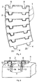
- Fig. 1 is a perspective top view of the carrying surface of a chain link according to a first embodiment of the invention.
- Fig. 2 is a perspective bottom view of the supporting surface of the chain link of Fig. 1 .
- Fig. 3 is a front view of the chain link of Fig. 1 .
- Fig. 4 is a plan view of the carrying surfaces of several chain links of Fig. 1 joined together.
- Fig. 5 is a front view of the chain link of Fig. 1 before insertion of its guide elements into the groove of the track.
- Fig. 6 is a front view of the chain link of Fig. 5 with the inserted guide elements.
- Fig. 7 is a front view of a second embodiment of a chain link.
- Fig. 8 is a plan view corresponding to Fig. 4 of the second embodiment.
- Fig. 9 is a front view of the second embodiment with the guide element inserted in the groove of the track.
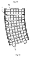
- Figs. 10 and 11 shows the chain link of Figs. 1-6 with an alternative carrying surface.
- Figs. 12 and 13 shows the chain link of Figs. 1-6 with a further embodiment of the carrying surface.
- Fig. 1 shows a chain link 1 made of synthetic material and comprising a substantially rectangular carrying surface 2 and two spaced apart eyes 4 on one edge of said carrying surface 2.
- the opposite edge of the link 1 comprises three eyes 16-18 with two recesses 8 between said eyes 16-18.
- the two eyes 4 on one chain link 1 are inserted into the recesses 8 of the adjacent chain link 1 so that the eyes 4 are located between said eyes 16, 17 and 17, 18.
- a hinge pin 5 is inserted through the bores of the eyes 16-18.
- the hinge pin 5 connects two adjacent chain links 1 pivotally about the axis of the hinge pin 5.
- the hinge pin 5 extends almost over the entire width of the chain links 1.
- the eyes 4, 16-18 for the hinge pin 5 and the pin 5 itself are located within the thickness of the chain link 1 and do not protrude above the carrying surface 2 or below the supporting surface 3 of the link 1.
- the hinge pins 5 and the hinge eyes or bores are designed such that the chain is capable of being flexed in the plane of transport.
- the plane of transport is defined by the carrying surfaces 2 of the successive links 1.
- the projecting eyes 4 are smaller than the recesses 8 so that are capable of slightly tilting inside the recesses 8.
- the projecting eyes 4 comprise elongated bores 20 which are represented in dashed lines in Fig. 4 .
- the elongated bores 20 extend through the major part of the length of the projecting eyes 4.
- the hinge pins 5 can slide inside the elongated bores 20 when the chain link 1 is rotated with respect to the adjacent chain link 1 in the horizontal plane of transport.
- Fig. 2 shows the chain link 1 of Fig. 1 as seen from below, whereby the supporting surface 3 and the location of the eyes 4 and of the hinge pins 5 with respect to the same may be appreciated.
- Fig. 2 further shows two projecting guide elements 9 which protrude from the supporting surface 3.
- said two guide elements 9 are straight projections protruding downwards from the supporting surface 3.
- the guide elements 9 extend perpendicularly with respect to the supporting surface 3 and they are located in the end-regions of the central eye 17 of the hinge link 1.
- Said projections or guide elements 9 serve to laterally guide the chain by engaging in the guiding recesses or grooves 7 of the track 6 (see Figs. 5 and 6 ).
- the two parallel guiding grooves 7 have a substantially rectangular shape and extend perpendicularly to the sliding surface 15 of the track 6. Note that it is also possible to provide guiding recesses with different shape.
- the guiding recesses may be open at the outside if the sliding surface is comprised between two guiding recesses.
- Fig. 5 shows that the guide elements 9 of the chain link 1 may easily be inserted into the grooves 7 of the track.
- the supporting surface 3 of the chain link 1 rests on a sliding surface 15 of the track and the guide elements 9 extend inside the grooves 7 of the track with little play with respect to the straight lateral surfaces 13, 14 of the two grooves 7.
- the guide elements 9 Due to the contact of the guide elements 9 with the lateral surfaces 13, 14 of the grooves 7 in the curved region of the track, the guide elements 9 prevent the chain links 1 from tilting and keep the outer edge of the links 1 on the sliding surface 15 of the track.
- the straight guide elements 9 within the straight grooves 7 ensure that the orientation of the chain link 1 remains parallel to the sliding surface 15 of the track.
- the shape of the guide elements 9 and the shape of the grooves 7 have to be such that the guide elements 9 remain inside the grooves 7 with little play with respect to the lateral surfaces 13, 14 of the grooves.
- the grooves 7 may be somewhat larger in the curved region of the track than the width of the guide elements 9. This accounts for the rotation of the guide elements 9 inside the grooves 7 as the chain is bent and the links 1 are rotated horizontally.
- lateral is meant lateral with respect to the central line of the chain in the direction of transportation.
- opposite is directed to surfaces with parallel normals that point in opposite directions.
- the guide elements may have a shape which ensures that their extension inside the two grooves 7 remains the same in the curved region of the track as compared to the straight region of the track.
- the distances of the two grooves 7 in the curved region may be smaller than in the straight region.
- Figs. 7 to 9 show a second embodiment of the present invention.
- the chain links 1 correspond to those of Figs. 1-6 and identical elements are identified by identical reference numbers.
- only one round guide element 9' is provided in the middle of each chain link 1.
- the guide element 9' has the form of a round pin protruding from the supporting surface 3 of the chain links 1'.
- the track has only one central groove 7' in the middle of the sliding surface 15. The width of this central groove 7' is less than 1 mm larger than the diameter of the round guide element 9' so that the guide element 9' is guided between both lateral surfaces of this groove 7' with little play.
- Figs. 10 and 11 show another embodiment of the chain 1 of Figs. 1-6 .
- the carrying surface 2 is essentially covered with a rubber strip that forms a pad 19.
- the pad 19 may be fastened to the chain link by chemical bonding (e.g. glue) or by mechanical means (e.g. screws). Rubber, by virtue of its anti-skid properties, prevents the transported product sliding off the conveyor chain, which is especially important in the bent sections of the track 6. It is obvious that rubber may be replaced by any other material with anti-skid properties without leaving the scope of the invention.
- Figs. 12 and 13 show a further embodiment of the chain of Figs. 1- 6 .
- the carrying surface 2 of the chain links 1 is provided with a support member 11 protruding upwards in a substantially perpendicular direction on each of its lateral edges.
- One or more axes 12 (two in the example illustrated in the figures) pass through said support member 11, extending in directions substantially parallel to the carrying surface 2.
- the axes 12 carry cylindrical rollers 10. These rollers 10 constitute the actual contact surface for products transported by the conveyor chain in this embodiment. As they can freely rotate about the axes 12, the rollers 10 reduce friction caused by the transported product and help absorb excessive stress exerted on the chain, thereby reducing its wear.
Abstract
Description
- The present invention relates to a chain conveyor comprising a track and a conveyor chain,
said track comprising at least one sliding surface that supports the chain and at least one portion curved in the plane of the sliding surface,
said chain having links comprising an upper carrying surface and a lower supporting surface which contacts said sliding surface, and a connecting system including at least two spaced eyes on one side of the link, at least one eye situated between said spaced eyes on the opposite side of the link and a hinge pin extending through said eyes,
the hinge pins and the hinge eyes being designed such that the chain is capable of flexing in the plane of transport defined by the carrying surfaces of the successive links,
said track comprising at least one recess and
the chain links comprising guide elements protruding downwards from the supporting surface into said recess, wherein the at least one recess of the track comprises two lateral surfaces extending downward from said sliding surface and parallel to one another and the guide elements are located adjacent to said two opposite lateral surfaces in the curved portion of the track. - In most cases the recess is formed by one or several grooves in said sliding surface.
- Such bent or curved chain conveyors are for example known from the documents
EP 0 286 173 B2 ,EP 0 207 577 orDE 85 30 825 U1 . They have chains capable of being curved in their main plane, i.e. of being flexed about an axis that runs perpendicular to the carrying surface of the chain links. The chain links comprise substantially rectangular carrying surfaces. These may be covered with an anti-skid pad of synthetic material with a thickness between 20% and 100% of the chain pitch, the latter being the space comprised between two successive axes. - The conveyor chain further comprises a connecting system which may be located between the carrying surface and the supporting surface. Said connecting system comprises at least two eyes placed on both sides of the link. Hinge pins are used for articulating adjacent links. The chains run on a track with at least one recess or groove. Guide elements on the lower surface of the chain links project into said groove.
- According to all three of the above documents a substantial distance or play is kept between the guide elements and the lateral surfaces of the groove in the curved portion of the track. This distance or play avoids blocking of the chain in said curved portion. The chain links are firmly pressed against the sliding surface in the curved portion of the track by magnetic elements in order to avoid lifting or tilting of the chain links in said curved portions of the track.
- A conveyor chain of this type may be used for transporting bottles, cans, boxes and similar containers.
- In order to keep the links from being lifted off the track, the systems proposed thus far have either used hook-like projections underneath the support surface of the links which engage with guiding rails in the track or magnets located on the guide under the zone of the hinge in order to generate a magnetic field (as can be seen in
European patent 0 286 173 B2 ). The magnetic field then attracts either the chain links or the hinge pins and provides a firm contact with the gliding surface of the track. - However, the hook-like projections tend to get jammed in the curved region and thus lead to excessive wear. Further, the track has to be disassembled in order to insert the chain links with the projecting portions of the hook-like projections into the track. It is not possible to simply take a chain link out of the track since the projecting portions of the chain link engages in a correspondingly formed recess in the track.
- Said magnetic means for avoiding lateral lifting off of the conveyor chain on the track in a bend present various disadvantages. The decelerating and retaining effects exerted on the chain by this magnetic attraction, independently of the weight transported and the speed, substantially increase the wear of the elements used.
-
WO 2004/052759 A1 discloses a claim modular and a modular chain conveyor. - The object of the present invention is to overcome the shortcomings of the conveyor chains of the prior art.
- This object is attained by the features of the characterising portion of
claim 1. - In other words, the recess or groove in the track has two opposite lateral surfaces that extend parallel to the centre line of the track. These lateral surfaces are almost contacted by the guide elements underneath the supporting surface, i.e. the guide elements extend with little play adjacent to the opposite lateral surfaces. The play between the guide elements and the lateral surfaces may be for example 0.1 mm in order to avoid blocking or jamming of the guide elements. One single guide element may be arranged closely adjacent to the two opposite lateral surfaces of one groove. Alternatively, two guide elements may be provided inside one groove and each guide element extends adjacent to one of the two lateral surfaces of one groove. In another alternative embodiment, there may be a plurality of grooves and a plurality of guide elements, each guide element protruding into one groove. Each guide element may extend closely adjacent to at least one lateral surface of the respective groove, such that at least two opposite lateral surfaces co-operate with little play with the guide elements. The term "opposite lateral surfaces" designates two surfaces with normals pointing in opposite directions. According to the invention, it is proposed to keep the guide elements closely adjacent to the lateral surfaces of the groove on two opposite sides with very little play (e.g. 0.1 mm). The zones where the guide elements approach the lateral surfaces are at a vertical distance from the supporting surface so that tilting of the chain links results in a physical contact between the guide elements and the two opposite lateral surfaces. This contact prevents further tilting. Lifting of the outer edge of the chain in a curved portion of the track is thus prevented without any additional magnetic force acting on the chain links.
- Since the two opposite lateral surfaces of the guide elements extend downwards from said sliding surface and parallel to one another, the guide elements of the chain links may simply be inserted by a linear movement in a direction parallel to the planes of the lateral surfaces. The lateral surfaces of the grooves or recesses may extend perpendicularly to the sliding surface so that the chain links can be lowered in a vertical direction onto the sliding surface while introducing the guide elements into the grooves.
- Preferably, the guide elements also comprise parallel lateral surfaces which extend perpendicularly to the supporting surface. Thus, straight vertical guide elements can be easily inserted into straight vertical grooves of the track. During operation the straight guide elements project into straight grooves and extend closely adjacent to the lateral walls of said grooves in the curved portion of the track. This avoids tilting of the chain link about the horizontal centre line of the chain.
- In one basic embodiment, each chain link can be provided in its centre with one straight and round guide pin as a guide element and the track can be provided with one groove for said guide pins. The width of the groove corresponds to the diameter of the guide pins so that they are guided in the groove with little play.
- In another embodiment, two guide elements are located underneath the supporting surface. These two guide elements run in two separate grooves in the track. They can either contact the two inner lateral surfaces of the two grooves or the two outer lateral surfaces of the two grooves or both. The shape of the guide elements and/or the distance between the lateral guide surfaces of the groove have to be adapted so that there is almost physical contact between the guide elements and the lateral surfaces of the groove without any jamming in the curved region of the track.
- The horizontal projection of the lateral surface of the guide elements may be arched with respect to the lateral surface of the groove. The curvature of the lateral surface of the guide element can correspond to the curvature of the corresponding surface of the groove in the curved region of the track. A convex outer surface of the guide element provides an enlarged contact area with the lateral surface of the groove and thus reduces friction and abrasion in case of contact between the guide element and the lateral surface of the groove due to lifting forces in the curved portion of the track.
- As an alternative to shaping the lateral surfaces of the guide elements, the distance between the two lateral guide surfaces of the groove or grooves in the track can be chosen such that the guide elements do not block or jam in the curved region of the track. If the two opposite lateral surfaces of the groove are located between the guide elements, the distance between the two opposite lateral surfaces in said curved portion should be slightly smaller than in a straight portion of the track. If, however, the guide elements are located between said two opposite lateral surfaces, the distance between the two opposite lateral surfaces in said curved portion can be slightly larger than in a straight portion of the track.
- If two guide elements contact the lateral surfaces of two grooves on both sides with little play, then the shape of the groove may be adjusted in the curved region of the track in order to avoid jamming. Depending on the shape of the two guide elements and the distance between these guide elements, the width of the two grooves and the distance between their centre line can be adjusted so that the guide elements stay in close contact with the respective walls of the grooves maintaining a small play for good guidance and avoiding jamming throughout the curved region of the track.
- The guide elements as well as the lateral surfaces of the groove preferably extend downwards from and perpendicularly to the sliding surface of the track or the supporting surface of the link.
- Preferably, a conveyor chain of the type explained in the introductory paragraph and described in
EP 0 286 173 B2 is provided which, according to the invention, is characterised by the fact that the links employ a straight guiding system which prevents lateral lifting of the chain and at the same time reduces costs and facilitates its installation, maintenance and replacement. The straight guide elements can easily be inserted into and removed from the grooves in the track. - The hinge pins may be made of nonmagnetic stainless steel, magnetic steel and even synthetic material. At least two eyes on one end of the link and one eye in the intermediate space between the two lateral eyes are provided. The hinge pin is preferably embraced by at least three spaced apart eyes connected with one of the links and by at least two eyes in the intermediate space between the spaced apart eyes. At least one guide projecting downwards from the underside of the chain link laterally guides the chain with respect to the tracks by running inside the groove of said chain conveyor. The hinge pin is preferably located between the carrying surface and the supporting surface, i.e. within the thickness of the chain link. It preferably extends at least over 50% and most preferably over 100% of the width of the chain link.
- Advantageously, the upper face of the carrying surface is covered with a material with anti-skid properties so as to avoid the transported product sliding off the conveyor chain. Alternatively, the surface where the transported product actually comes into contact with the chain may consist of rollers so as to reduce friction and absorb stress.
- Note that it is not necessary that each chain link has the guide elements. The chain may comprise one or more links without guide elements. These links are guided and kept in contact with the track due to the guide elements of the adjacent chain links.
- The invention further refers to a bent or straight segment for a chain conveyor, comprising at least one guiding track and at least one conveyor chain, wherein the guiding track has at least one sliding surface and a guiding groove which preferably receives only the guide element of the chain. The hinge pin of the latter remains preferably located above the carrying surface of the bent or straight segment.
- The manner of execution of the invention as well as the advantages resulting therefrom will be more clearly understood with the help of the following description of preferred embodiments of the invention with reference to the accompanying drawings.
-
Fig. 1 is a perspective top view of the carrying surface of a chain link according to a first embodiment of the invention. -
Fig. 2 is a perspective bottom view of the supporting surface of the chain link ofFig. 1 . -
Fig. 3 is a front view of the chain link ofFig. 1 . -
Fig. 4 is a plan view of the carrying surfaces of several chain links ofFig. 1 joined together. -
Fig. 5 is a front view of the chain link ofFig. 1 before insertion of its guide elements into the groove of the track. -
Fig. 6 is a front view of the chain link ofFig. 5 with the inserted guide elements. -
Fig. 7 is a front view of a second embodiment of a chain link. -
Fig. 8 is a plan view corresponding toFig. 4 of the second embodiment. -
Fig. 9 is a front view of the second embodiment with the guide element inserted in the groove of the track. -
Figs. 10 and 11 shows the chain link ofFigs. 1-6 with an alternative carrying surface. -
Figs. 12 and 13 shows the chain link ofFigs. 1-6 with a further embodiment of the carrying surface. - Referring first to
Figs. 1-6 , a first embodiment of the invention is illustrated.Fig. 1 shows achain link 1 made of synthetic material and comprising a substantially rectangular carryingsurface 2 and two spaced aparteyes 4 on one edge of said carryingsurface 2. The opposite edge of thelink 1 comprises three eyes 16-18 with tworecesses 8 between said eyes 16-18. The twoeyes 4 on onechain link 1 are inserted into therecesses 8 of theadjacent chain link 1 so that theeyes 4 are located between saideyes hinge pin 5 is inserted through the bores of the eyes 16-18. Thehinge pin 5 connects twoadjacent chain links 1 pivotally about the axis of thehinge pin 5. Thehinge pin 5 extends almost over the entire width of the chain links 1. Theeyes 4, 16-18 for thehinge pin 5 and thepin 5 itself are located within the thickness of thechain link 1 and do not protrude above the carryingsurface 2 or below the supportingsurface 3 of thelink 1. - Further, as can be seen in
Fig. 4 , the hinge pins 5 and the hinge eyes or bores are designed such that the chain is capable of being flexed in the plane of transport. The plane of transport is defined by the carryingsurfaces 2 of thesuccessive links 1. The projectingeyes 4 are smaller than therecesses 8 so that are capable of slightly tilting inside therecesses 8. The projectingeyes 4 comprise elongated bores 20 which are represented in dashed lines inFig. 4 . The elongated bores 20 extend through the major part of the length of the projectingeyes 4. The hinge pins 5 can slide inside the elongated bores 20 when thechain link 1 is rotated with respect to theadjacent chain link 1 in the horizontal plane of transport. -
Fig. 2 shows thechain link 1 ofFig. 1 as seen from below, whereby the supportingsurface 3 and the location of theeyes 4 and of the hinge pins 5 with respect to the same may be appreciated.Fig. 2 further shows two projectingguide elements 9 which protrude from the supportingsurface 3. - As shown in
Fig. 3 , said twoguide elements 9 are straight projections protruding downwards from the supportingsurface 3. Theguide elements 9 extend perpendicularly with respect to the supportingsurface 3 and they are located in the end-regions of thecentral eye 17 of thehinge link 1. Said projections or guideelements 9 serve to laterally guide the chain by engaging in the guiding recesses orgrooves 7 of the track 6 (seeFigs. 5 and6 ). The twoparallel guiding grooves 7 have a substantially rectangular shape and extend perpendicularly to the slidingsurface 15 of the track 6. Note that it is also possible to provide guiding recesses with different shape. The guiding recesses may be open at the outside if the sliding surface is comprised between two guiding recesses. -
Fig. 5 shows that theguide elements 9 of thechain link 1 may easily be inserted into thegrooves 7 of the track. The supportingsurface 3 of thechain link 1 rests on a slidingsurface 15 of the track and theguide elements 9 extend inside thegrooves 7 of the track with little play with respect to the straight lateral surfaces 13, 14 of the twogrooves 7. - Due to the contact of the
guide elements 9 with the lateral surfaces 13, 14 of thegrooves 7 in the curved region of the track, theguide elements 9 prevent thechain links 1 from tilting and keep the outer edge of thelinks 1 on the slidingsurface 15 of the track. Thestraight guide elements 9 within thestraight grooves 7 ensure that the orientation of thechain link 1 remains parallel to the slidingsurface 15 of the track. - Good results are obtained if the
guide elements 9 are guided by the lateral surfaces 13, 14 of thegrooves 7 on both sides. However, it is sufficient if only twoopposite surfaces grooves 7, i.e. the twoouter surfaces 13 or theinner surfaces 14, contact theguide element 9 with little play. - The shape of the
guide elements 9 and the shape of thegrooves 7 have to be such that theguide elements 9 remain inside thegrooves 7 with little play with respect to the lateral surfaces 13, 14 of the grooves. Thegrooves 7 may be somewhat larger in the curved region of the track than the width of theguide elements 9. This accounts for the rotation of theguide elements 9 inside thegrooves 7 as the chain is bent and thelinks 1 are rotated horizontally. In order to stabilise the chain links 1 on the slidingsurface 15 of the track it is only necessary to maintain a punctual or linear contact zone between theguide elements 9 and two opposite lateral surfaces of thegrooves 7. In the present description, by "lateral" is meant lateral with respect to the central line of the chain in the direction of transportation. The term "opposite" is directed to surfaces with parallel normals that point in opposite directions. - Alternatively, the guide elements may have a shape which ensures that their extension inside the two
grooves 7 remains the same in the curved region of the track as compared to the straight region of the track. The distances of the twogrooves 7 in the curved region, however, may be smaller than in the straight region. - It is also possible to provide a different number of grooves on the track, e.g. one groove or three grooves. As long as two opposite lateral surfaces, i.e. surfaces which extend generally in the direction of transportation, are contacted by the guide elements at a certain distance underneath the sliding
surface 15, thechain link 1 will be prevented from tilting. -
Figs. 7 to 9 show a second embodiment of the present invention. The chain links 1 correspond to those ofFigs. 1-6 and identical elements are identified by identical reference numbers. According to this second embodiment, only oneround guide element 9' is provided in the middle of eachchain link 1. Theguide element 9' has the form of a round pin protruding from the supportingsurface 3 of the chain links 1'. The track has only one central groove 7' in the middle of the slidingsurface 15. The width of this central groove 7' is less than 1 mm larger than the diameter of theround guide element 9' so that theguide element 9' is guided between both lateral surfaces of this groove 7' with little play. -
Figs. 10 and 11 show another embodiment of thechain 1 ofFigs. 1-6 . In this embodiment, the carryingsurface 2 is essentially covered with a rubber strip that forms apad 19. Thepad 19 may be fastened to the chain link by chemical bonding (e.g. glue) or by mechanical means (e.g. screws). Rubber, by virtue of its anti-skid properties, prevents the transported product sliding off the conveyor chain, which is especially important in the bent sections of the track 6. It is obvious that rubber may be replaced by any other material with anti-skid properties without leaving the scope of the invention. -
Figs. 12 and 13 show a further embodiment of the chain ofFigs. 1- 6 . In this embodiment, the carryingsurface 2 of the chain links 1 is provided with a support member 11 protruding upwards in a substantially perpendicular direction on each of its lateral edges. One or more axes 12 (two in the example illustrated in the figures) pass through said support member 11, extending in directions substantially parallel to the carryingsurface 2. Theaxes 12 carrycylindrical rollers 10. Theserollers 10 constitute the actual contact surface for products transported by the conveyor chain in this embodiment. As they can freely rotate about theaxes 12, therollers 10 reduce friction caused by the transported product and help absorb excessive stress exerted on the chain, thereby reducing its wear. - Obviously, a person skilled in the art may come up with certain variants of the embodiments described herein without leaving the scope of the invention as set out in the claims.
- Reference numbers:
- 1
- chain link
- 2
- carrying surface
- 3
- supporting surface
- 4
- eye
- 5
- hinge pin
- 6
- track
- 7,7'
- recess, groove
- 8
- recess
- 9,9'
- guide element
- 10
- roller
- 11
- support member
- 12
- axis
- 13
- lateral surface
- 14
- lateral surface
- 15
- sliding surface
- 16
- outer eye
- 17
- central eye
- 18
- outer eye
- 19
- pad
- 20
- elongated bore
Claims (10)
- A chain conveyor comprising a track and a conveyor chain,
said track comprising at least one sliding surface (15) that supports the chain and at least one portion curved in the plane of the sliding surface (15),
said chain having links (1) comprising an upper carrying surface (2) and a lower supporting surface (3) which contacts said sliding surface (15), and a connecting system including at least two spaced eyes (4) on one side of the link (1), at least one eye (17) situated between said spaced eyes (4) on the opposite side of the link (1) and a hinge pin (5) extending through said eyes (4,17),
the hinge pins (5) and the hinge eyes (4,16-18) being designed such that the chain is capable of flexing in the plane of transport defined by the carrying surfaces (2) of the successive links (1),
said track comprising at least one recess (7,7') and
said chain links (1) comprising guide elements (9,9') protruding downwards from the supporting surface (3) into said recess (7,7'),
wherein the at least one recess (7,7') of the track comprises two opposite lateral surfaces (13,14) extending downwards from said sliding surface (15) and parallel to one another and the guide elements (9,9') are located adjacent to said two opposite lateral surfaces (13,14) in the curved portion of the track, characterized in that the guide elements (9,9') are located adjacent to said two opposite lateral surfaces (13,14) in the curved portion of the track with little play, and that the zones where the guide elements (9,9') approach the lateral surfaces (13,14) are at a vertical distance from the supporting surface (3) so that the tilting of the chain links results in a physical contact between the guide elements (9,9') and the two opposite lateral surfaces (13,14), which contact prevents further tilting. - A chain conveyor according to claim 1, characterized in that the guide elements (9,9') comprise lateral surfaces extending downwards from said supporting surface (3) and parallel to one another.
- A chain conveyor according to claim 1 or 2, characterized in that the lateral surfaces (13,14) of the recesses (7,7') extend perpendicularly to said sliding surface (15).
- A chain conveyor according to any one of the preceding claims, characterized in that the horizontal projection of the lateral surface of the guide elements (9') is arched with respect to the lateral surface (13,14) of the recess (7') towards the centre of the track.
- A chain conveyor according to any one of the preceding claims, characterized in that the two opposite lateral surfaces (14) are located between the guide elements (9) and the distance between the two opposite lateral surfaces (14) in said curved portion is slightly smaller than in a straight portion of the track.
- A chain conveyor according to any one of the preceding claims, characterized in that the guide elements (9) are located, between said two opposite lateral surfaces (14) and the distance between the two opposite lateral surfaces (14) in said curved portion is slightly larger than in a straight portion of the track.
- A chain conveyor according to any one of the preceding claims, characterized in that the carrying surfaces (2) comprise at least one of the following features:they are substantially rectangular shape,they are made of synthetic material or rubber,their thickness equals between 20% and 100% of the pitch of the chain,- they are composed of a pad (19) bonded to the upper surface of the chain link (1),- they are provided with rolling elements (10) for the reduction of frictional forces.
- A chain conveyor according to any one of the preceding claims, characterized in that the connecting system comprises at least one of the following features:it is located between the carrying surface (2) and the supporting surface (3),it extends at least over 50% of the width of the chain link (1),its hinge pins (5) are made of nonmagnetic stainless steel,its hinge pins (5) are made of magnetic steel,its hinge pins (5) are made of synthetic material.
- A chain conveyor according to any one of the preceding claims, characterized in that the track comprises at least one of the following features:at least one groove (7,7') which forms the recess of the track;the lateral surfaces (13,14) of the at least one recess (7,7') extend downwards from and perpendicularly to the sliding surface (15);two parallel grooves (7) for receiving one guide element (9) each.
- A chain conveyor according to any one of the preceding claims, characterized in that at least one chain link without a guide element is arranged between two chain links (1) having guide elements (9,9').
Priority Applications (4)
| Application Number | Priority Date | Filing Date | Title |
|---|---|---|---|
| ES05103194T ES2349085T3 (en) | 2005-04-20 | 2005-04-20 | CHAIN CONVEYOR |
| DE602005022276T DE602005022276D1 (en) | 2005-04-20 | 2005-04-20 | chain conveyors |
| AT05103194T ATE473936T1 (en) | 2005-04-20 | 2005-04-20 | CHAIN CONVEYOR |
| EP05103194A EP1714920B1 (en) | 2005-04-20 | 2005-04-20 | Chain conveyor |
Applications Claiming Priority (1)
| Application Number | Priority Date | Filing Date | Title |
|---|---|---|---|
| EP05103194A EP1714920B1 (en) | 2005-04-20 | 2005-04-20 | Chain conveyor |
Publications (2)
| Publication Number | Publication Date |
|---|---|
| EP1714920A1 EP1714920A1 (en) | 2006-10-25 |
| EP1714920B1 true EP1714920B1 (en) | 2010-07-14 |
Family
ID=35229635
Family Applications (1)
| Application Number | Title | Priority Date | Filing Date |
|---|---|---|---|
| EP05103194A Active EP1714920B1 (en) | 2005-04-20 | 2005-04-20 | Chain conveyor |
Country Status (4)
| Country | Link |
|---|---|
| EP (1) | EP1714920B1 (en) |
| AT (1) | ATE473936T1 (en) |
| DE (1) | DE602005022276D1 (en) |
| ES (1) | ES2349085T3 (en) |
Families Citing this family (1)
| Publication number | Priority date | Publication date | Assignee | Title |
|---|---|---|---|---|
| ITBO20130715A1 (en) * | 2013-12-23 | 2015-06-24 | Bett Sistemi Srl | ARTICULATED KNIT CONVEYOR BELT. |
Family Cites Families (3)
| Publication number | Priority date | Publication date | Assignee | Title |
|---|---|---|---|---|
| DE10019051A1 (en) * | 2000-04-18 | 2001-10-25 | Flexon Systemplast Gmbh | Curve guidance for a conveyor chain |
| DE10027229A1 (en) * | 2000-05-31 | 2001-12-06 | Flexon Systemplast Gmbh | Conveyor chain comprises elements which incorporate inner and/or outer side guide surfaces made of a material whose coefficient of friction is lower than the coefficient of friction of the rest of the chain element material |
| NL1022132C2 (en) * | 2002-12-10 | 2004-06-11 | Mcc Nederland | Chain module and modular chain conveyor. |
-
2005
- 2005-04-20 EP EP05103194A patent/EP1714920B1/en active Active
- 2005-04-20 ES ES05103194T patent/ES2349085T3/en active Active
- 2005-04-20 AT AT05103194T patent/ATE473936T1/en not_active IP Right Cessation
- 2005-04-20 DE DE602005022276T patent/DE602005022276D1/en active Active
Also Published As
| Publication number | Publication date |
|---|---|
| ATE473936T1 (en) | 2010-07-15 |
| ES2349085T3 (en) | 2010-12-27 |
| EP1714920A1 (en) | 2006-10-25 |
| DE602005022276D1 (en) | 2010-08-26 |
Similar Documents
| Publication | Publication Date | Title |
|---|---|---|
| EP2509895B1 (en) | Conveyor transfer system with floating transfer platform | |
| CN101395075B (en) | Conveyor switch | |
| US7963389B2 (en) | Conveyor | |
| US4760908A (en) | Sorter conveyor | |
| US6758328B2 (en) | Chain for three-dimensional transfer line | |
| DK169212B1 (en) | Chain conveyor, conveyor chain and a curve segment for forming such a chain conveyor track | |
| US8011496B2 (en) | Conveyor means for articles | |
| US10046914B1 (en) | Chain link, conveyor chain and conveyor apparatus | |
| US9902569B2 (en) | Sorting system having cover plates closing gaps between support structures | |
| KR20040010515A (en) | Cross conveyor chain device | |
| US5014625A (en) | Linear motor driven trolley conveyor | |
| CA2316995C (en) | Curved conveyor | |
| US6415905B1 (en) | Transport device | |
| US6805234B2 (en) | Roller conveyor | |
| US4765455A (en) | Chain conveyor reducing longitudinal contact pressure between conveyed articles | |
| US20060021847A1 (en) | Roller conveyor | |
| EP1714920B1 (en) | Chain conveyor | |
| US5960938A (en) | Conveyor for cantilevered loads | |
| US6481567B2 (en) | Conveyor system with intermediate drive and related method | |
| US20050109579A1 (en) | Pallet conveyor | |
| US4732266A (en) | Bearing construction for mounting carriers on an endless chain elevator | |
| EP0697005B1 (en) | Transport device with load carriers for the transport of goods | |
| AU2018294386B2 (en) | Conveying device having two conveying carts and cover for covering a space between the two conveying carts | |
| CN110626712A (en) | Belt tracking device and system | |
| EP1209100A1 (en) | Conveyor for conveying bulk material |
Legal Events
| Date | Code | Title | Description |
|---|---|---|---|
| PUAI | Public reference made under article 153(3) epc to a published international application that has entered the european phase |
Free format text: ORIGINAL CODE: 0009012 |
|
| AK | Designated contracting states |
Kind code of ref document: A1 Designated state(s): AT BE BG CH CY CZ DE DK EE ES FI FR GB GR HU IE IS IT LI LT LU MC NL PL PT RO SE SI SK TR |
|
| AX | Request for extension of the european patent |
Extension state: AL BA HR LV MK YU |
|
| 17P | Request for examination filed |
Effective date: 20070424 |
|
| AKX | Designation fees paid |
Designated state(s): AT BE BG CH CY CZ DE DK EE ES FI FR GB GR HU IE IS IT LI LT LU MC NL PL PT RO SE SI SK TR |
|
| 17Q | First examination report despatched |
Effective date: 20070918 |
|
| GRAP | Despatch of communication of intention to grant a patent |
Free format text: ORIGINAL CODE: EPIDOSNIGR1 |
|
| GRAC | Information related to communication of intention to grant a patent modified |
Free format text: ORIGINAL CODE: EPIDOSCIGR1 |
|
| GRAS | Grant fee paid |
Free format text: ORIGINAL CODE: EPIDOSNIGR3 |
|
| GRAA | (expected) grant |
Free format text: ORIGINAL CODE: 0009210 |
|
| AK | Designated contracting states |
Kind code of ref document: B1 Designated state(s): AT BE BG CH CY CZ DE DK EE ES FI FR GB GR HU IE IS IT LI LT LU MC NL PL PT RO SE SI SK TR |
|
| REG | Reference to a national code |
Ref country code: GB Ref legal event code: FG4D |
|
| REG | Reference to a national code |
Ref country code: CH Ref legal event code: EP |
|
| REG | Reference to a national code |
Ref country code: IE Ref legal event code: FG4D |
|
| REF | Corresponds to: |
Ref document number: 602005022276 Country of ref document: DE Date of ref document: 20100826 Kind code of ref document: P |
|
| REG | Reference to a national code |
Ref country code: NL Ref legal event code: VDEP Effective date: 20100714 |
|
| LTIE | Lt: invalidation of european patent or patent extension |
Effective date: 20100714 |
|
| REG | Reference to a national code |
Ref country code: ES Ref legal event code: FG2A Effective date: 20101214 |
|
| PG25 | Lapsed in a contracting state [announced via postgrant information from national office to epo] |
Ref country code: FI Free format text: LAPSE BECAUSE OF FAILURE TO SUBMIT A TRANSLATION OF THE DESCRIPTION OR TO PAY THE FEE WITHIN THE PRESCRIBED TIME-LIMIT Effective date: 20100714 Ref country code: LT Free format text: LAPSE BECAUSE OF FAILURE TO SUBMIT A TRANSLATION OF THE DESCRIPTION OR TO PAY THE FEE WITHIN THE PRESCRIBED TIME-LIMIT Effective date: 20100714 Ref country code: AT Free format text: LAPSE BECAUSE OF FAILURE TO SUBMIT A TRANSLATION OF THE DESCRIPTION OR TO PAY THE FEE WITHIN THE PRESCRIBED TIME-LIMIT Effective date: 20100714 Ref country code: NL Free format text: LAPSE BECAUSE OF FAILURE TO SUBMIT A TRANSLATION OF THE DESCRIPTION OR TO PAY THE FEE WITHIN THE PRESCRIBED TIME-LIMIT Effective date: 20100714 |
|
| PG25 | Lapsed in a contracting state [announced via postgrant information from national office to epo] |
Ref country code: PT Free format text: LAPSE BECAUSE OF FAILURE TO SUBMIT A TRANSLATION OF THE DESCRIPTION OR TO PAY THE FEE WITHIN THE PRESCRIBED TIME-LIMIT Effective date: 20101115 Ref country code: BG Free format text: LAPSE BECAUSE OF FAILURE TO SUBMIT A TRANSLATION OF THE DESCRIPTION OR TO PAY THE FEE WITHIN THE PRESCRIBED TIME-LIMIT Effective date: 20101014 Ref country code: CY Free format text: LAPSE BECAUSE OF FAILURE TO SUBMIT A TRANSLATION OF THE DESCRIPTION OR TO PAY THE FEE WITHIN THE PRESCRIBED TIME-LIMIT Effective date: 20100714 Ref country code: IS Free format text: LAPSE BECAUSE OF FAILURE TO SUBMIT A TRANSLATION OF THE DESCRIPTION OR TO PAY THE FEE WITHIN THE PRESCRIBED TIME-LIMIT Effective date: 20101114 Ref country code: PL Free format text: LAPSE BECAUSE OF FAILURE TO SUBMIT A TRANSLATION OF THE DESCRIPTION OR TO PAY THE FEE WITHIN THE PRESCRIBED TIME-LIMIT Effective date: 20100714 Ref country code: SI Free format text: LAPSE BECAUSE OF FAILURE TO SUBMIT A TRANSLATION OF THE DESCRIPTION OR TO PAY THE FEE WITHIN THE PRESCRIBED TIME-LIMIT Effective date: 20100714 |
|
| PG25 | Lapsed in a contracting state [announced via postgrant information from national office to epo] |
Ref country code: BE Free format text: LAPSE BECAUSE OF FAILURE TO SUBMIT A TRANSLATION OF THE DESCRIPTION OR TO PAY THE FEE WITHIN THE PRESCRIBED TIME-LIMIT Effective date: 20100714 Ref country code: SE Free format text: LAPSE BECAUSE OF FAILURE TO SUBMIT A TRANSLATION OF THE DESCRIPTION OR TO PAY THE FEE WITHIN THE PRESCRIBED TIME-LIMIT Effective date: 20100714 |
|
| PG25 | Lapsed in a contracting state [announced via postgrant information from national office to epo] |
Ref country code: DK Free format text: LAPSE BECAUSE OF FAILURE TO SUBMIT A TRANSLATION OF THE DESCRIPTION OR TO PAY THE FEE WITHIN THE PRESCRIBED TIME-LIMIT Effective date: 20100714 |
|
| PLBE | No opposition filed within time limit |
Free format text: ORIGINAL CODE: 0009261 |
|
| STAA | Information on the status of an ep patent application or granted ep patent |
Free format text: STATUS: NO OPPOSITION FILED WITHIN TIME LIMIT |
|
| PG25 | Lapsed in a contracting state [announced via postgrant information from national office to epo] |
Ref country code: RO Free format text: LAPSE BECAUSE OF FAILURE TO SUBMIT A TRANSLATION OF THE DESCRIPTION OR TO PAY THE FEE WITHIN THE PRESCRIBED TIME-LIMIT Effective date: 20100714 Ref country code: IT Free format text: LAPSE BECAUSE OF FAILURE TO SUBMIT A TRANSLATION OF THE DESCRIPTION OR TO PAY THE FEE WITHIN THE PRESCRIBED TIME-LIMIT Effective date: 20100714 Ref country code: CZ Free format text: LAPSE BECAUSE OF FAILURE TO SUBMIT A TRANSLATION OF THE DESCRIPTION OR TO PAY THE FEE WITHIN THE PRESCRIBED TIME-LIMIT Effective date: 20100714 Ref country code: SK Free format text: LAPSE BECAUSE OF FAILURE TO SUBMIT A TRANSLATION OF THE DESCRIPTION OR TO PAY THE FEE WITHIN THE PRESCRIBED TIME-LIMIT Effective date: 20100714 Ref country code: EE Free format text: LAPSE BECAUSE OF FAILURE TO SUBMIT A TRANSLATION OF THE DESCRIPTION OR TO PAY THE FEE WITHIN THE PRESCRIBED TIME-LIMIT Effective date: 20100714 |
|
| 26N | No opposition filed |
Effective date: 20110415 |
|
| REG | Reference to a national code |
Ref country code: DE Ref legal event code: R097 Ref document number: 602005022276 Country of ref document: DE Effective date: 20110415 |
|
| PG25 | Lapsed in a contracting state [announced via postgrant information from national office to epo] |
Ref country code: MC Free format text: LAPSE BECAUSE OF NON-PAYMENT OF DUE FEES Effective date: 20110430 |
|
| REG | Reference to a national code |
Ref country code: CH Ref legal event code: PL |
|
| PG25 | Lapsed in a contracting state [announced via postgrant information from national office to epo] |
Ref country code: CH Free format text: LAPSE BECAUSE OF NON-PAYMENT OF DUE FEES Effective date: 20110430 Ref country code: LI Free format text: LAPSE BECAUSE OF NON-PAYMENT OF DUE FEES Effective date: 20110430 |
|
| REG | Reference to a national code |
Ref country code: IE Ref legal event code: MM4A |
|
| PG25 | Lapsed in a contracting state [announced via postgrant information from national office to epo] |
Ref country code: IE Free format text: LAPSE BECAUSE OF NON-PAYMENT OF DUE FEES Effective date: 20110420 |
|
| PG25 | Lapsed in a contracting state [announced via postgrant information from national office to epo] |
Ref country code: LU Free format text: LAPSE BECAUSE OF NON-PAYMENT OF DUE FEES Effective date: 20110420 |
|
| PG25 | Lapsed in a contracting state [announced via postgrant information from national office to epo] |
Ref country code: TR Free format text: LAPSE BECAUSE OF FAILURE TO SUBMIT A TRANSLATION OF THE DESCRIPTION OR TO PAY THE FEE WITHIN THE PRESCRIBED TIME-LIMIT Effective date: 20100714 |
|
| PG25 | Lapsed in a contracting state [announced via postgrant information from national office to epo] |
Ref country code: HU Free format text: LAPSE BECAUSE OF FAILURE TO SUBMIT A TRANSLATION OF THE DESCRIPTION OR TO PAY THE FEE WITHIN THE PRESCRIBED TIME-LIMIT Effective date: 20100714 |
|
| PG25 | Lapsed in a contracting state [announced via postgrant information from national office to epo] |
Ref country code: GR Free format text: LAPSE BECAUSE OF FAILURE TO SUBMIT A TRANSLATION OF THE DESCRIPTION OR TO PAY THE FEE WITHIN THE PRESCRIBED TIME-LIMIT Effective date: 20100714 |
|
| REG | Reference to a national code |
Ref country code: FR Ref legal event code: PLFP Year of fee payment: 12 |
|
| REG | Reference to a national code |
Ref country code: FR Ref legal event code: PLFP Year of fee payment: 13 |
|
| REG | Reference to a national code |
Ref country code: FR Ref legal event code: PLFP Year of fee payment: 14 |
|
| PGFP | Annual fee paid to national office [announced via postgrant information from national office to epo] |
Ref country code: FR Payment date: 20230425 Year of fee payment: 19 Ref country code: ES Payment date: 20230503 Year of fee payment: 19 Ref country code: DE Payment date: 20230425 Year of fee payment: 19 |
|
| PGFP | Annual fee paid to national office [announced via postgrant information from national office to epo] |
Ref country code: GB Payment date: 20230420 Year of fee payment: 19 |