EP1714842A1 - Seatbelt retractor assembly - Google Patents
Seatbelt retractor assembly Download PDFInfo
- Publication number
- EP1714842A1 EP1714842A1 EP06005280A EP06005280A EP1714842A1 EP 1714842 A1 EP1714842 A1 EP 1714842A1 EP 06005280 A EP06005280 A EP 06005280A EP 06005280 A EP06005280 A EP 06005280A EP 1714842 A1 EP1714842 A1 EP 1714842A1
- Authority
- EP
- European Patent Office
- Prior art keywords
- actuator
- seatbelt retractor
- open slot
- retractor assembly
- contacting portion
- Prior art date
- Legal status (The legal status is an assumption and is not a legal conclusion. Google has not performed a legal analysis and makes no representation as to the accuracy of the status listed.)
- Granted
Links
- 230000001133 acceleration Effects 0.000 claims description 7
- 230000000284 resting effect Effects 0.000 claims description 2
- 230000003068 static effect Effects 0.000 claims description 2
- 239000002991 molded plastic Substances 0.000 claims 1
- 239000000463 material Substances 0.000 description 5
- 230000000694 effects Effects 0.000 description 4
- 230000009467 reduction Effects 0.000 description 4
- 230000004044 response Effects 0.000 description 3
- 230000005484 gravity Effects 0.000 description 2
- 230000010355 oscillation Effects 0.000 description 2
- 239000004033 plastic Substances 0.000 description 2
- 229920003023 plastic Polymers 0.000 description 2
- -1 polypropylene Polymers 0.000 description 2
- 239000004677 Nylon Substances 0.000 description 1
- 239000004698 Polyethylene Substances 0.000 description 1
- 239000004743 Polypropylene Substances 0.000 description 1
- 229910000831 Steel Inorganic materials 0.000 description 1
- 125000000218 acetic acid group Chemical group C(C)(=O)* 0.000 description 1
- XAGFODPZIPBFFR-UHFFFAOYSA-N aluminium Chemical compound [Al] XAGFODPZIPBFFR-UHFFFAOYSA-N 0.000 description 1
- 229910052782 aluminium Inorganic materials 0.000 description 1
- 238000010586 diagram Methods 0.000 description 1
- 238000001746 injection moulding Methods 0.000 description 1
- 238000011089 mechanical engineering Methods 0.000 description 1
- 229920001778 nylon Polymers 0.000 description 1
- 229920000573 polyethylene Polymers 0.000 description 1
- 229920001155 polypropylene Polymers 0.000 description 1
- 230000004043 responsiveness Effects 0.000 description 1
- 230000035945 sensitivity Effects 0.000 description 1
- 239000007779 soft material Substances 0.000 description 1
- 239000000243 solution Substances 0.000 description 1
- 239000010959 steel Substances 0.000 description 1
- 239000011800 void material Substances 0.000 description 1
Images


Classifications
-
- B—PERFORMING OPERATIONS; TRANSPORTING
- B60—VEHICLES IN GENERAL
- B60R—VEHICLES, VEHICLE FITTINGS, OR VEHICLE PARTS, NOT OTHERWISE PROVIDED FOR
- B60R22/00—Safety belts or body harnesses in vehicles
- B60R22/34—Belt retractors, e.g. reels
- B60R22/36—Belt retractors, e.g. reels self-locking in an emergency
- B60R22/40—Belt retractors, e.g. reels self-locking in an emergency responsive only to vehicle movement
Definitions
- a seatbelt for a passenger vehicle typically has a seatbelt retractor assembly that serves to retract the belt into its housing.
- the belt is wound upon a spool in the housing.
- the spool winds a retraction spring, which later retracts the unused portion of the belt onto the spool or withdraws the belt into its housing when not in use.
- the seatbelt retractor has a lock that prevents the seatbelt from extending further from its housing.
- the lock may be actuated by an inertial sensor, which responds to changes in vehicle speed during the crash. When a large deceleration is detected, the inertial sensor triggers the lock of the seatbelt retractor to lock the spool and secures the safety belt in place during the crash.
- the inertial sensor has an inertial sensor mass that moves in response to changes in speed of the vehicle.
- This mass is mechanically linked to the lock by an actuator.
- the actuator moves and causes movement of a locking pawl that locks the lock when the mass has moved in excess of a predetermined amount.
- the actuator rests on a surface of the mass. This surface is typically angled so that movement of the mass causes rapid movement of the actuator and consequently the locking pawl. While rapid movement of the components of the inertial sensor and lock are desirable for safety, this same feature causes undesirable noise during normal vehicle operation.
- Another source of retractor rattle involves intermittent contact between the sensor actuator and the sensor mass as the actuator bounces on the guide surface of the sensor mass, a rattle noise can be heard.
- this noise can be reduced by cushioning the guide surface with a soft material. This, however, can reduce the sensitivity of the sensor mass by creating undesirable friction between the contacting surfaces of the actuator and the guide surface.
- noise absorbing wraps around the retractor assembly have been added which reduce audible noise levels in the passenger compartment of the vehicle.
- This need is met by a seatbelt retractor assembly according to Claim 1 that has an inertial sensor that detects changes in vehicle speed.
- the inertial sensor has an inertial sensor mass, which is linked to a seatbelt retractor locking pawl by an actuator.
- the actuator moves with the mass by riding on its surface.
- the inventor has discovered that a significant amount of noise arises from movement of the actuator and components linked to it. Accordingly, in contrast to conventional designs, the actuator is modified to add a slight springiness to the contact sensor portion in a manner that removes objectionable high frequency noise.
- the inventive seatbelt retractor assembly has a seatbelt retractor, an actuator for locking and unlocking the seatbelt retractor, and an inertial sensor mass for detecting changes in vehicle acceleration.
- the inertial sensor mass has a guide surface for interacting with the actuator. The guide surface is movable between an unlocking position wherein the actuator unlocks the seatbelt retractor and a locking position wherein the actuator locks the seatbelt retractor.
- the actuator has a pivotal actuator arm with a surface contacting portion resting on the guide surface of the sensor mass and an open slot above the surface contacting portion.
- the surface contacting portion is connected to the pivotal actuator arm by a beam structure.
- the surface contacting portion has a generally rounded or substantially hemispherical protruding bottom for contacting the guide surface.
- the open slot above the surface contacting portion extends above the generally rounded bottom portion and the beam structure.
- the connecting beam structure has a spring rate K beam , K beam being sufficient to keep the open slot open during normal sensor vibration.
- K beam being sufficient to keep the open slot open during normal sensor vibration.
- This enables the beam to be sufficiently spring like and is designed to have an oscillating frequency f defined in Elements of Vibration Analysis, L. Meirovitch, 1986 by f 1 2 ⁇ K beam m eff , wherein m eff equals F static /gravity, as seen in Fig 3A.
- the actuator can be made of plastic and molded as a unitary structure having an effective mass m eff with the open slot geometry optimally selected by using the parameter K beam m eff ; the value of this determines the cutoff frequency f for impact noise, accordingly the spring rate K beam and effective mass m eff are determined to be at or below this cutoff frequency f.
- This actuator with a spring like cushioned surface contacting portion dramatically reduces rattle noises above the cutoff frequency, f which can be as low as the designer wishes however is typically kept above 300 Hz.
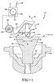
- FIG. 1 is a side view of an inventive seatbelt retractor assembly 10.
- the seatbelt retractor assembly 10 has a seatbelt retractor 14, which houses a seatbelt 18 as shown.
- the seatbelt retractor assembly 10 has a locking pawl 22, which is selectively engageable with a locking wheel 28.
- the locking wheel 28 has teeth to engage the locking pawl 22.
- the seatbelt retractor 14 prevents the seatbelt 18 from extending further from seatbelt retractor 14.
- the seatbelt retractor 14 has an inertial sensor, here an inertial sensor mass 30, which is responsive to vehicle acceleration.
- the inertial sensor mass 30 rests on a sensor housing 24, here shown schematically, and tips in the direction of either arrow P or arrow Q in response to vehicle acceleration.
- the inertial sensor mass 30 is linked to the locking pawl 22 by an actuator 26, an arm, which causes the locking pawl 22 to engage or disengage the locking wheel 28 depending upon the position of the inertial sensor mass 30. While the locking pawl 22 is shown schematically as a separate component from the actuator 26, the locking pawl 22 and actuator 26 may, in fact, be a single part.
- the actuator 26 interacts with a guide surface 34 through an actuator surface contacting portion 54.
- the actuator surface contacting portion 54 has an actuator curvature 58.
- the actuator curvature 58 as illustrated is generally a hemispherical surface or approximates a rounded protruding bottom which directly contacts the guide surface 34.
- An open slot 57 is shown above the surface contacting portion 54 and a beam structure 56 as shown.
- Figure 1 illustrates the inertial sensor mass 30 in an unlocking position.
- the actuator 26 maintains the locking pawl 22 in an unlocked condition, allowing the seatbelt 18 to be withdrawn from the seatbelt retractor 14.
- the actuator 26 is pivotally mounted by a pivot 19 so as to rotate in the direction of arrow R in response to movement of the inertial sensor mass 30 in the direction of arrow P or in the direction of arrow Q.
- the inertial sensor mass 30 responds by moving either in the direction of arrow P or in the direction of arrow Q. In either direction, the actuator 26 moves in the direction of arrow R.
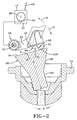
- the inertial sensor mass 30 is shown having moved in the direction of arrow P from the unlocking position 38 shown in Figure 1 to a locking position 42. Movement of the inertial sensor mass 30 has caused the actuator 26 to move in the direction of arrow R from the position shown in Figure 1. This movement of the actuator 26 causes the locking pawl 22 to engage the teeth of the locking wheel 28. The return movement of the inertial sensor mass 30 in the direction of arrow Q towards the unlocking position 38 causes a return of the actuator 26 in the direction of arrow S to the position shown in Figure 1.
- the guide surface 34 is located on a wide portion 46 above a narrow portion 50. While the figures show a particular shape of an exemplary sensor mass 30 upon which guide surface 34 sits, guide surface 34 may be implemented as any shape such as a sphere or cone shape.
- actuator 26 can occasionally "jump" in direction R, momentarily losing contact between guide surface 34 and surface contacting portion 54. When actuator 26 rebounds back in direction S, contact will be re-established. Such intermittent contact can produce an audible rattle noise, which this invention seeks to eliminate.
- Beam structure 56 reduces the rattle noise by softening the contact between actuator 26 and guide surface 34.
- the underlying principle of the invention can best be understood by using a spring-mass analogy.
- the open slot 57 provides space for a limited amount of deflection of the actuator surface contacting portion 54 and the beam structure 56 relative to the actuator arm 25 of the actuator 26.
- the surface contacting portion 54 has a force F applied tending to put a load on the beam structure 56 to deflect it in the direction X.
- This load can be due to the static weight of the actuator 26 and it can also be due to impacts between the actuator 26 and the sensor 30.
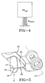
- Figure 4 shows an idealized spring-mass system analogous to the invention.
- An equivalent mass, m eff is supported by a spring whose spring rate is K beam .
- This is equivalent to the actuator of figure 5 where the effective mass of the actuator 26 is supported by beam structure 56.
- the beam structure 56 can have more complicated geometry in which case more sophisticated analysis is required to compute the oscillation frequency f.
- Symbol F refers to a force and f to a frequency.
- the ratio of effective mass to contact stiffness indicates contact sharpness or impact stiffness.
- noise reductions can be easily accomplished by adjusting the open slot length defining the beam length (I), the beam thickness (c) or beam width (b).
- the geometry of the beam structure 56 can be adjusted to change the overall spring rate up or down as required to achieve the desired oscillator frequency to achieve a reduction in actuator rattle noise.
- the actuator 26 is shown in a perspective view showing the actuator arm 25, the pivot axis 19, the open slot 57 with the surface contacting portion 54 and beam structure 56.
- the actuator can be formed as unitary single piece structure by injection molding a plastic material.
- the actuator is made of acetyl, polypropylene, nylon or polyethylene or similar light weight easily molded material.
- the choice of materials could be almost any material including steel and aluminum as long as the desired spring like cushioning effect is achieved to reduce the contact noise.
- the open slot 57 is shown as a straight grooved opening in the actuator it is understood the shape of the opening can be varied to any variety of openings including wavy, triangular or curved with the resultant underlying beam structure optionally having an adjacent corresponding shape.
- the important aspect is that the open slot 57 provides a cushioning effect by providing a spring like beam structure 56 capable of minute deflections under normal vibrational inputs from a moving vehicle. Under an acceleration sufficient to create a locking of the seatbelt retractor the gap in the actuator 26 at the open slot 57 will close or otherwise be sufficiently small as to allow timely locking of the device. This also creates a lower impact noise as the actuator 26 moves to a locking engagement as shown in figure 2.
- open slot 57 refers to a void volume. In the embodiment described in figures 1 and 5 the open slot 57 was located directly above the surface contacting portion 54 and extending inwardly above the beam structure 56, the open slot 57 providing a gap sufficient to allow a flexure of the portions 54 and 56 and being completely open across the entire width of the surface contacting portion 54 and beam structure 56 during normal driving conditions.
- open slot 57 is shown generally extending horizontally it is understood the open slot can be inclined or even bent extending above the surface contacting portion 54 into the actuator arm 25 to define a beam structure 56 of any desired geometric shape. Additionally, open slot 57 may have more complicated geometry such as a sawtooth pattern, for example. One skilled in the art will realize the usefulness of a nonplanar open slot.
- a second embodiment of the invention is shown wherein the actuator 26 has an open slot 57 that extends substantially vertically with an optional short enlarged end 59 such that the beam structure 56 as shown forms a relatively thin hinge which can reduce the impact noise upon locking into the lock position 42 as well as providing a spring like effect during normal driving conditions.
- the open slot 57 is at least partially closed in the locked position and the flexibility of the beam structure 56 is sufficient to provide a noise reduction under normal driving condition use as well.
- the open slot 57, 59 is above the surface contacting portion 54 but offset or located inwardly and extending generally vertically cutting across the width of the actuator arm 25.
Landscapes
- Engineering & Computer Science (AREA)
- Mechanical Engineering (AREA)
- Automotive Seat Belt Assembly (AREA)
- Details Of Garments (AREA)
Abstract
Description
- A seatbelt for a passenger vehicle typically has a seatbelt retractor assembly that serves to retract the belt into its housing. The belt is wound upon a spool in the housing. When the belt is drawn or protracted from its housing, the spool winds a retraction spring, which later retracts the unused portion of the belt onto the spool or withdraws the belt into its housing when not in use.
- In a crash the seatbelt retractor has a lock that prevents the seatbelt from extending further from its housing. The lock may be actuated by an inertial sensor, which responds to changes in vehicle speed during the crash. When a large deceleration is detected, the inertial sensor triggers the lock of the seatbelt retractor to lock the spool and secures the safety belt in place during the crash.
- The inertial sensor has an inertial sensor mass that moves in response to changes in speed of the vehicle. This mass is mechanically linked to the lock by an actuator. When the mass moves, the actuator moves and causes movement of a locking pawl that locks the lock when the mass has moved in excess of a predetermined amount. The actuator rests on a surface of the mass. This surface is typically angled so that movement of the mass causes rapid movement of the actuator and consequently the locking pawl. While rapid movement of the components of the inertial sensor and lock are desirable for safety, this same feature causes undesirable noise during normal vehicle operation. Another source of retractor rattle involves intermittent contact between the sensor actuator and the sensor mass as the actuator bounces on the guide surface of the sensor mass, a rattle noise can be heard. Typically, this noise can be reduced by cushioning the guide surface with a soft material. This, however, can reduce the sensitivity of the sensor mass by creating undesirable friction between the contacting surfaces of the actuator and the guide surface. As an alternative noise absorbing wraps around the retractor assembly have been added which reduce audible noise levels in the passenger compartment of the vehicle. These solutions increase cost and in some cases reduce the inertial sensor's responsiveness.
- A need therefore exists for a seatbelt retractor that reduces noise from the foregoing moveable parts. This need is met by a seatbelt retractor assembly according to
Claim 1 that has an inertial sensor that detects changes in vehicle speed. The inertial sensor has an inertial sensor mass, which is linked to a seatbelt retractor locking pawl by an actuator. The actuator moves with the mass by riding on its surface. The inventor has discovered that a significant amount of noise arises from movement of the actuator and components linked to it. Accordingly, in contrast to conventional designs, the actuator is modified to add a slight springiness to the contact sensor portion in a manner that removes objectionable high frequency noise. - The inventive seatbelt retractor assembly has a seatbelt retractor, an actuator for locking and unlocking the seatbelt retractor, and an inertial sensor mass for detecting changes in vehicle acceleration. The inertial sensor mass has a guide surface for interacting with the actuator. The guide surface is movable between an unlocking position wherein the actuator unlocks the seatbelt retractor and a locking position wherein the actuator locks the seatbelt retractor.
The actuator has a pivotal actuator arm with a surface contacting portion resting on the guide surface of the sensor mass and an open slot above the surface contacting portion. - The surface contacting portion is connected to the pivotal actuator arm by a beam structure. The surface contacting portion has a generally rounded or substantially hemispherical protruding bottom for contacting the guide surface. The open slot above the surface contacting portion extends above the generally rounded bottom portion and the beam structure.
- The connecting beam structure has a spring rate Kbeam, Kbeam being sufficient to keep the open slot open during normal sensor vibration. This enables the beam to be sufficiently spring like and is designed to have an oscillating frequency f defined in Elements of Vibration Analysis, L. Meirovitch, 1986 by

- The actuator can be made of plastic and molded as a unitary structure having an effective mass meff with the open slot geometry optimally selected by using the parameter

- Figure 1 is a side view of the inventive seatbelt retractor, showing a first embodiment inertial sensor mass, actuator and seatbelt retractor in an unlocked position.
- Figure 2 is a side view of the inventive seatbelt retractor, showing a first embodiment inertial sensor mass, actuator and seatbelt retractor in a locked position.
- Figure 3 outlines the engineering parameters in designing the actuator.
- Figure 3A illustrates the actuator of the present invention and the relationship between Fstatic and meff.
- Figure 4 is a schematic spring mass.
- Figure 5 illustrates a perspective view of the actuator.
- Figure 6 illustrates a second embodiment of the invention.
- Figure 1 is a side view of an inventive
seatbelt retractor assembly 10. The seatbeltretractor assembly 10 has aseatbelt retractor 14, which houses aseatbelt 18 as shown. Like conventional seatbelt retractors, the seatbeltretractor assembly 10 has alocking pawl 22, which is selectively engageable with alocking wheel 28. Thelocking wheel 28 has teeth to engage thelocking pawl 22. When thelocking pawl 22 is engaged with thelocking wheel 22, theseatbelt retractor 14 prevents theseatbelt 18 from extending further from seatbeltretractor 14. - As shown, the
seatbelt retractor 14 has an inertial sensor, here aninertial sensor mass 30, which is responsive to vehicle acceleration. Theinertial sensor mass 30 rests on asensor housing 24, here shown schematically, and tips in the direction of either arrow P or arrow Q in response to vehicle acceleration. Theinertial sensor mass 30 is linked to thelocking pawl 22 by anactuator 26, an arm, which causes thelocking pawl 22 to engage or disengage thelocking wheel 28 depending upon the position of theinertial sensor mass 30. While thelocking pawl 22 is shown schematically as a separate component from theactuator 26, thelocking pawl 22 andactuator 26 may, in fact, be a single part. As shown in Figures 1 and 2, theactuator 26 interacts with aguide surface 34 through an actuatorsurface contacting portion 54. The actuatorsurface contacting portion 54 has anactuator curvature 58. Theactuator curvature 58 as illustrated is generally a hemispherical surface or approximates a rounded protruding bottom which directly contacts theguide surface 34. At the near zero vehicle acceleration theactuator 26 contacts theguide surface 34 at thecontact point 100. Anopen slot 57 is shown above thesurface contacting portion 54 and abeam structure 56 as shown. - Figure 1 illustrates the
inertial sensor mass 30 in an unlocking position. When in this position, theactuator 26 maintains thelocking pawl 22 in an unlocked condition, allowing theseatbelt 18 to be withdrawn from theseatbelt retractor 14. Theactuator 26 is pivotally mounted by apivot 19 so as to rotate in the direction of arrow R in response to movement of theinertial sensor mass 30 in the direction of arrow P or in the direction of arrow Q. In the event of a quick acceleration or deceleration of a vehicle, such as in a crash, theinertial sensor mass 30 responds by moving either in the direction of arrow P or in the direction of arrow Q. In either direction, theactuator 26 moves in the direction of arrow R. - As shown in Figure 2, the
inertial sensor mass 30 is shown having moved in the direction of arrow P from theunlocking position 38 shown in Figure 1 to alocking position 42. Movement of theinertial sensor mass 30 has caused theactuator 26 to move in the direction of arrow R from the position shown in Figure 1. This movement of theactuator 26 causes thelocking pawl 22 to engage the teeth of thelocking wheel 28. The return movement of theinertial sensor mass 30 in the direction of arrow Q towards theunlocking position 38 causes a return of theactuator 26 in the direction of arrow S to the position shown in Figure 1. - The first embodiment of the invention will now be explained in detail with reference to Figure 1. As shown in Figure 1, the
guide surface 34 is located on awide portion 46 above anarrow portion 50. While the figures show a particular shape of anexemplary sensor mass 30 upon whichguide surface 34 sits,guide surface 34 may be implemented as any shape such as a sphere or cone shape. Under small amplitude vibration loading,actuator 26 can occasionally "jump" in direction R, momentarily losing contact betweenguide surface 34 andsurface contacting portion 54. When actuator 26 rebounds back in direction S, contact will be re-established. Such intermittent contact can produce an audible rattle noise, which this invention seeks to eliminate.Beam structure 56 reduces the rattle noise by softening the contact betweenactuator 26 and guidesurface 34. Ifbeam structure 56 is made to be softer, the intermittent contact noise becomes quieter. Ifbeam structure 56 is made to be stiffer, the intermittent contact noise becomes louder. Ifopen slot 57 is removed completely, (i.e. in the absence of this invention) then there is no cushion at all and the intermittent contact noise would be as loud as possible.Open slot 57 is sized to be large enough that deflections ofbeam structure 56 due to vehicle vibrations will be unimpeded. Under higher loads, however, such as may occur during a rapid change in vehicle speed,open slot 57 is small enough to restrictbeam structure 56 so that rapid locking can still occur with thesensor mass 30 tilting in the direction P or Q as shown in figure 2. - With reference to figures 3, 3A and 4, the underlying principle of the invention can best be understood by using a spring-mass analogy. In other words the
open slot 57 provides space for a limited amount of deflection of the actuatorsurface contacting portion 54 and thebeam structure 56 relative to theactuator arm 25 of theactuator 26. - As shown in figure 3 the
surface contacting portion 54 has a force F applied tending to put a load on thebeam structure 56 to deflect it in the direction X. This load can be due to the static weight of theactuator 26 and it can also be due to impacts between the actuator 26 and thesensor 30. - Using classical beam theory, an idealized beam stiffness can be computed as follows: The beam structure as found in Marks'Standard Handbook of Mechanical Engineering, 10th edition, has a thickness (c) and a width (b) and a length (I). Accordingly the beam structure acts like a leaf spring wherein the spring rate or spring constant


- Figure 3A shows a Free Body Diagram associated with the
actuator 26. Considering the sum of the torques about thepivot 19, it is seen that the actuator contact force, Fstatic, must equal meff * g where meff is the equivalent mass ofactuator 26 if the CG (center of gravity) of theactuator 26 were placed directly over theactuator contact point 100; thus meff = Fstatic /g. - Figure 4 shows an idealized spring-mass system analogous to the invention. An equivalent mass, meff is supported by a spring whose spring rate is Kbeam. This is equivalent to the actuator of figure 5 where the effective mass of the
actuator 26 is supported bybeam structure 56. This means that the oscillation frequency (f) of theactuator 26 can be assumed to meet the equation
Note that thebeam structure 56 can have more complicated geometry in which case more sophisticated analysis is required to compute the oscillation frequency f. Symbol F refers to a force and f to a frequency. The ratio of effective mass to contact stiffness indicates contact sharpness or impact stiffness. Accordingly the spring effect of theopen slot 57 andbeam structure 56 acts much like a low pass filter, wherein noise reduction were observed wherein (f) = 300 Hz, (more typically (f) will be greater than 300 Hz generally 1000 Hz ― 1500 Hz however (f) can be designed to be as high as 20,000 Hz ― the upper frequency limit of human hearing―and still have some remaining benefit). These noise reductions can be easily accomplished by adjusting the open slot length defining the beam length (I), the beam thickness (c) or beam width (b). In other words the geometry of thebeam structure 56 can be adjusted to change the overall spring rate up or down as required to achieve the desired oscillator frequency to achieve a reduction in actuator rattle noise. - With reference to figure 5, the
actuator 26 is shown in a perspective view showing theactuator arm 25, thepivot axis 19, theopen slot 57 with thesurface contacting portion 54 andbeam structure 56. As shown the actuator can be formed as unitary single piece structure by injection molding a plastic material. Preferably the actuator is made of acetyl, polypropylene, nylon or polyethylene or similar light weight easily molded material. The choice of materials could be almost any material including steel and aluminum as long as the desired spring like cushioning effect is achieved to reduce the contact noise. - While the
open slot 57 is shown as a straight grooved opening in the actuator it is understood the shape of the opening can be varied to any variety of openings including wavy, triangular or curved with the resultant underlying beam structure optionally having an adjacent corresponding shape. The important aspect is that theopen slot 57 provides a cushioning effect by providing a spring likebeam structure 56 capable of minute deflections under normal vibrational inputs from a moving vehicle. Under an acceleration sufficient to create a locking of the seatbelt retractor the gap in theactuator 26 at theopen slot 57 will close or otherwise be sufficiently small as to allow timely locking of the device. This also creates a lower impact noise as theactuator 26 moves to a locking engagement as shown in figure 2. - As used herein the term
open slot 57 refers to a void volume. In the embodiment described in figures 1 and 5 theopen slot 57 was located directly above thesurface contacting portion 54 and extending inwardly above thebeam structure 56, theopen slot 57 providing a gap sufficient to allow a flexure of theportions surface contacting portion 54 andbeam structure 56 during normal driving conditions. - While the
open slot 57 is shown generally extending horizontally it is understood the open slot can be inclined or even bent extending above thesurface contacting portion 54 into theactuator arm 25 to define abeam structure 56 of any desired geometric shape. Additionally,open slot 57 may have more complicated geometry such as a sawtooth pattern, for example. One skilled in the art will realize the usefulness of a nonplanar open slot. - With reference to figure 6 a second embodiment of the invention is shown wherein the
actuator 26 has anopen slot 57 that extends substantially vertically with an optional short enlarged end 59 such that thebeam structure 56 as shown forms a relatively thin hinge which can reduce the impact noise upon locking into thelock position 42 as well as providing a spring like effect during normal driving conditions. - Preferably the
open slot 57 is at least partially closed in the locked position and the flexibility of thebeam structure 56 is sufficient to provide a noise reduction under normal driving condition use as well. As shown theopen slot 57, 59 is above thesurface contacting portion 54 but offset or located inwardly and extending generally vertically cutting across the width of theactuator arm 25.
Claims (12)
- A seatbelt retractor assembly (10) comprising:a seatbelt retractor (14);an actuator (26) for locking and unlocking the seatbelt retractor (14);an inertial sensor mass (30) for detecting changes in vehicle acceleration, the inertial sensor mass (30) having a guide surface (34) for interacting with the actuator (26);the guide surface (34) is movable between an unlocking position wherein the actuator (26) unlocks the seatbelt retractor (14) and a locking position wherein the actuator (26) locks the seatbelt retractor (14); andwherein the actuator (26) has a pivotal actuator arm (25) with a surface contacting portion (54) resting on the guide surface (34) and an open slot (57) above the surface contacting portion (54).
- A seatbelt retractor assembly (10) according to claim 1 wherein the surface contacting portion (54) has a generally rounded protruding bottom for contacting the guide surface (34).
- A seatbelt retractor assembly (10) according to claim 2 wherein the surface contacting portion (54) is connected to the pivotal actuator arm (25) by a beam structure (56).
- A seatbelt retractor assembly (10) according to claim 3 wherein the open slot (57) above the surface contacting portion (54) extends above the generally rounded protruding bottom and the beam structure (56).
- A seatbelt retractor assembly (10) according to Claim any of claims 1 - 4 wherein the beam structure (56) has a spring rate Kbeam, wherein Kbeam is sufficient to keep the open slot (57) open during normal sensor vibration.
- A seatbelt retractor assembly (10) according to any of Claims 2 - 5 wherein the open slot (57) is located above the generally rounded protruding bottom.
- A seatbelt retractor assembly (10) according to Claim 6 wherein the open slot (57) extends into the actuator arm (25).
- A seatbelt retractor assembly (10) according to any of Claims 1 - 7 wherein the actuator (26) has an oscillating frequency f defined as

- A seatbelt retractor assembly (10) according to Claim 7 wherein the actuator (26) has an effective mass meff of less than 150 grams.
- A seatbelt retractor assembly (10) according to any of Claims 1 - 9 wherein the actuator (26) is a molded plastic component.
- A seatbelt retractor assembly (10) according to any of claims 3 - 10 wherein the open slot (57) extends substantially vertically and is located above but offset inwardly relative to the contacting surface portion.
- A seatbelt retractor assembly (10) according to claim 11 wherein the open slot (57) has an enlarged open end above the beam structure (56).
Applications Claiming Priority (1)
| Application Number | Priority Date | Filing Date | Title |
|---|---|---|---|
| US11/107,154 US7455256B2 (en) | 2005-04-18 | 2005-04-18 | Seatbelt retractor having a cushioned sensor actuator |
Publications (2)
| Publication Number | Publication Date |
|---|---|
| EP1714842A1 true EP1714842A1 (en) | 2006-10-25 |
| EP1714842B1 EP1714842B1 (en) | 2007-12-05 |
Family
ID=36677972
Family Applications (1)
| Application Number | Title | Priority Date | Filing Date |
|---|---|---|---|
| EP06005280A Expired - Lifetime EP1714842B1 (en) | 2005-04-18 | 2006-03-15 | Seatbelt retractor assembly |
Country Status (4)
| Country | Link |
|---|---|
| US (1) | US7455256B2 (en) |
| EP (1) | EP1714842B1 (en) |
| AT (1) | ATE380134T1 (en) |
| DE (1) | DE602006000290T2 (en) |
Families Citing this family (18)
| Publication number | Priority date | Publication date | Assignee | Title |
|---|---|---|---|---|
| US7263750B2 (en) | 2005-06-09 | 2007-09-04 | Amsafe, Inc. | Buckle assembly having single release for multiple belt connectors |
| WO2010037103A1 (en) | 2008-09-29 | 2010-04-01 | Amsafe, Inc. | Tensioning apparatuses for occupant restraint systems and associated systems and methods |
| US8469401B2 (en) | 2009-02-23 | 2013-06-25 | Amsafe, Inc. | Seat harness pretensioner |
| US8393645B2 (en) | 2009-11-02 | 2013-03-12 | Amsafe Commercial Products, Inc. | Devices for adjusting tension in seat belts and other restraint system webs, and associated methods |
| US8683666B2 (en) | 2009-11-04 | 2014-04-01 | Amsafe Commercial Products, Inc. | Restraint system buckle components having tactile surfaces, and associated methods of use and manufacture |
| US8627554B1 (en) | 2010-05-03 | 2014-01-14 | Amsafe, Inc. (Phoenix Group) | Buckle assemblies with swivel and dual release features and associated methods of use and manufacture |
| US8777323B2 (en) | 2010-07-20 | 2014-07-15 | Amsafe, Inc. | Restraint harnesses and associated methods of use and manufacture |
| USD655223S1 (en) | 2010-09-15 | 2012-03-06 | Amsafe Commercial Products, Inc. | Buckle assembly |
| USD661619S1 (en) | 2010-09-15 | 2012-06-12 | Amsafe Commercial Products, Inc. | Buckle assembly |
| US8979129B2 (en) * | 2011-04-22 | 2015-03-17 | Tk Holdings Inc. | Seat belt retractor |
| US9022483B2 (en) | 2012-06-07 | 2015-05-05 | Shield Restraint Systems, Inc. | Seatbelt buckle tongue assembly |
| US8708370B1 (en) | 2012-07-23 | 2014-04-29 | John Barker | Safety enhancement for a safety belt |
| EP2958453A4 (en) | 2013-02-19 | 2016-07-27 | Amsafe Inc | Buckle assemblies with lift latches and associated methods and systems |
| US9277788B2 (en) | 2013-02-19 | 2016-03-08 | Amsafe, Inc. | Dual release buckle assemblies and associated systems and methods |
| WO2016100566A1 (en) | 2014-12-16 | 2016-06-23 | Shield Restraint Systems, Inc. | Web adjusters for use with restraint systems and associated methods of use and manufacture |
| US10604259B2 (en) | 2016-01-20 | 2020-03-31 | Amsafe, Inc. | Occupant restraint systems having extending restraints, and associated systems and methods |
| US9814282B2 (en) | 2016-02-02 | 2017-11-14 | Shield Restraint Systems, Inc. | Harsh environment buckle assemblies and associated systems and methods |
| US10611334B2 (en) | 2017-02-07 | 2020-04-07 | Shield Restraint Systems, Inc. | Web adjuster |
Citations (4)
| Publication number | Priority date | Publication date | Assignee | Title |
|---|---|---|---|---|
| US3930622A (en) * | 1974-06-13 | 1976-01-06 | American Safety Equipment Corporation | Energy storing safety belt retractor |
| WO1987006545A1 (en) * | 1986-04-30 | 1987-11-05 | Autoliv Development Ab | Meshing means, controlled by an inertia body, for toothed control wheels in locking devices for vehicle safety belts |
| US5507449A (en) * | 1994-08-12 | 1996-04-16 | Trw Vehicle Safety Systems Inc. | Seat belt retractor with noise suppression |
| DE19758495A1 (en) * | 1997-08-12 | 1999-02-25 | Hs Tech & Design | Seat belt retractor |
Family Cites Families (7)
| Publication number | Priority date | Publication date | Assignee | Title |
|---|---|---|---|---|
| US4166592A (en) * | 1975-10-03 | 1979-09-04 | Gateway Industries | Seat belt retractor |
| US4040576A (en) * | 1975-12-10 | 1977-08-09 | The Firestone Tire & Rubber Company | Retractor lock and pawl saddle therefor |
| US4084840A (en) * | 1976-02-23 | 1978-04-18 | Allied Chemical Corporation | Vehicle sensitive retractor |
| JPS5646768Y2 (en) * | 1977-11-02 | 1981-11-02 | ||
| US4760975A (en) * | 1987-06-30 | 1988-08-02 | Gateway Industries, Inc. | Seat belt retractor |
| GB9215855D0 (en) * | 1992-07-25 | 1992-09-09 | Bsrd Ltd | Improvements to emergency locking passenger safety belt mechanisms |
| DE19835673A1 (en) * | 1998-08-06 | 2000-02-10 | Takata Europ Gmbh | Seat belt device with acceleration sensor |
-
2005
- 2005-04-18 US US11/107,154 patent/US7455256B2/en not_active Expired - Fee Related
-
2006
- 2006-03-15 DE DE602006000290T patent/DE602006000290T2/en not_active Expired - Lifetime
- 2006-03-15 AT AT06005280T patent/ATE380134T1/en not_active IP Right Cessation
- 2006-03-15 EP EP06005280A patent/EP1714842B1/en not_active Expired - Lifetime
Patent Citations (4)
| Publication number | Priority date | Publication date | Assignee | Title |
|---|---|---|---|---|
| US3930622A (en) * | 1974-06-13 | 1976-01-06 | American Safety Equipment Corporation | Energy storing safety belt retractor |
| WO1987006545A1 (en) * | 1986-04-30 | 1987-11-05 | Autoliv Development Ab | Meshing means, controlled by an inertia body, for toothed control wheels in locking devices for vehicle safety belts |
| US5507449A (en) * | 1994-08-12 | 1996-04-16 | Trw Vehicle Safety Systems Inc. | Seat belt retractor with noise suppression |
| DE19758495A1 (en) * | 1997-08-12 | 1999-02-25 | Hs Tech & Design | Seat belt retractor |
Non-Patent Citations (1)
| Title |
|---|
| L. MEIROVITCH, ELEMENTS OF VIBRATION ANALYSIS, 1986 |
Also Published As
| Publication number | Publication date |
|---|---|
| ATE380134T1 (en) | 2007-12-15 |
| DE602006000290T2 (en) | 2008-11-27 |
| US7455256B2 (en) | 2008-11-25 |
| US20060231666A1 (en) | 2006-10-19 |
| EP1714842B1 (en) | 2007-12-05 |
| DE602006000290D1 (en) | 2008-01-17 |
Similar Documents
| Publication | Publication Date | Title |
|---|---|---|
| EP1714842B1 (en) | Seatbelt retractor assembly | |
| US7416150B2 (en) | Overmolded inertia sensor mass for a seat belt retractor | |
| US5443224A (en) | Emergency locking passenger safety belt mechanisms | |
| JP4384609B2 (en) | Child vehicle seat | |
| US6164581A (en) | Low noise self-compensating vehicle sensor and retractor | |
| JP2008156841A (en) | Lid body locking structure of storage box for vehicle | |
| JP4488598B2 (en) | Seat belt guide | |
| JP4727081B2 (en) | Seat belt guide | |
| US6578810B2 (en) | Seat slide apparatus | |
| EP1707454B1 (en) | Seatbelt retractor assembly | |
| US8388040B2 (en) | Lock-out device for vehicle compartment with lid | |
| JP2007045317A (en) | Retractor for seat belt | |
| JP2018108820A (en) | Lock mechanism for belt retractor | |
| JP2002362312A (en) | Seat belt device | |
| US6971718B2 (en) | Child safety seat | |
| JP5735635B2 (en) | Seat belt device | |
| US6688547B1 (en) | Self compensating inertia sensor | |
| JPH11165659A (en) | Seat belt mounting structure in cab | |
| JP2012250617A (en) | Attaching part structure of vehicle sensor for seat belt retractor | |
| KR100463155B1 (en) | Center console box for automobile | |
| JPH081159Y2 (en) | Car seat belt equipment | |
| JPH1134799A (en) | Body acceleration sensor for seat belt | |
| JP3633334B2 (en) | Seat belt retractor | |
| KR101741809B1 (en) | Seat Belt Locking Apparatus | |
| EP3984836A1 (en) | A vehicle-sensitive sensor and self-locking belt-retractor |
Legal Events
| Date | Code | Title | Description |
|---|---|---|---|
| PUAI | Public reference made under article 153(3) epc to a published international application that has entered the european phase |
Free format text: ORIGINAL CODE: 0009012 |
|
| AK | Designated contracting states |
Kind code of ref document: A1 Designated state(s): AT BE BG CH CY CZ DE DK EE ES FI FR GB GR HU IE IS IT LI LT LU LV MC NL PL PT RO SE SI SK TR |
|
| AX | Request for extension of the european patent |
Extension state: AL BA HR MK YU |
|
| 17P | Request for examination filed |
Effective date: 20070424 |
|
| AKX | Designation fees paid |
Designated state(s): AT BE BG CH CY CZ DE DK EE ES FI FR GB GR HU IE IS IT LI LT LU LV MC NL PL PT RO SE SI SK TR |
|
| GRAP | Despatch of communication of intention to grant a patent |
Free format text: ORIGINAL CODE: EPIDOSNIGR1 |
|
| GRAS | Grant fee paid |
Free format text: ORIGINAL CODE: EPIDOSNIGR3 |
|
| GRAA | (expected) grant |
Free format text: ORIGINAL CODE: 0009210 |
|
| AK | Designated contracting states |
Kind code of ref document: B1 Designated state(s): AT BE BG CH CY CZ DE DK EE ES FI FR GB GR HU IE IS IT LI LT LU LV MC NL PL PT RO SE SI SK TR |
|
| REG | Reference to a national code |
Ref country code: GB Ref legal event code: FG4D |
|
| REG | Reference to a national code |
Ref country code: IE Ref legal event code: FG4D |
|
| REG | Reference to a national code |
Ref country code: CH Ref legal event code: EP |
|
| REF | Corresponds to: |
Ref document number: 602006000290 Country of ref document: DE Date of ref document: 20080117 Kind code of ref document: P |
|
| PG25 | Lapsed in a contracting state [announced via postgrant information from national office to epo] |
Ref country code: CH Free format text: LAPSE BECAUSE OF FAILURE TO SUBMIT A TRANSLATION OF THE DESCRIPTION OR TO PAY THE FEE WITHIN THE PRESCRIBED TIME-LIMIT Effective date: 20071205 Ref country code: ES Free format text: LAPSE BECAUSE OF FAILURE TO SUBMIT A TRANSLATION OF THE DESCRIPTION OR TO PAY THE FEE WITHIN THE PRESCRIBED TIME-LIMIT Effective date: 20080316 Ref country code: LI Free format text: LAPSE BECAUSE OF FAILURE TO SUBMIT A TRANSLATION OF THE DESCRIPTION OR TO PAY THE FEE WITHIN THE PRESCRIBED TIME-LIMIT Effective date: 20071205 Ref country code: NL Free format text: LAPSE BECAUSE OF FAILURE TO SUBMIT A TRANSLATION OF THE DESCRIPTION OR TO PAY THE FEE WITHIN THE PRESCRIBED TIME-LIMIT Effective date: 20071205 Ref country code: SE Free format text: LAPSE BECAUSE OF FAILURE TO SUBMIT A TRANSLATION OF THE DESCRIPTION OR TO PAY THE FEE WITHIN THE PRESCRIBED TIME-LIMIT Effective date: 20080305 |
|
| PG25 | Lapsed in a contracting state [announced via postgrant information from national office to epo] |
Ref country code: FI Free format text: LAPSE BECAUSE OF FAILURE TO SUBMIT A TRANSLATION OF THE DESCRIPTION OR TO PAY THE FEE WITHIN THE PRESCRIBED TIME-LIMIT Effective date: 20071205 Ref country code: SI Free format text: LAPSE BECAUSE OF FAILURE TO SUBMIT A TRANSLATION OF THE DESCRIPTION OR TO PAY THE FEE WITHIN THE PRESCRIBED TIME-LIMIT Effective date: 20071205 Ref country code: LT Free format text: LAPSE BECAUSE OF FAILURE TO SUBMIT A TRANSLATION OF THE DESCRIPTION OR TO PAY THE FEE WITHIN THE PRESCRIBED TIME-LIMIT Effective date: 20071205 Ref country code: LV Free format text: LAPSE BECAUSE OF FAILURE TO SUBMIT A TRANSLATION OF THE DESCRIPTION OR TO PAY THE FEE WITHIN THE PRESCRIBED TIME-LIMIT Effective date: 20071205 Ref country code: PL Free format text: LAPSE BECAUSE OF FAILURE TO SUBMIT A TRANSLATION OF THE DESCRIPTION OR TO PAY THE FEE WITHIN THE PRESCRIBED TIME-LIMIT Effective date: 20071205 |
|
| NLV1 | Nl: lapsed or annulled due to failure to fulfill the requirements of art. 29p and 29m of the patents act | ||
| REG | Reference to a national code |
Ref country code: CH Ref legal event code: PL |
|
| PG25 | Lapsed in a contracting state [announced via postgrant information from national office to epo] |
Ref country code: AT Free format text: LAPSE BECAUSE OF FAILURE TO SUBMIT A TRANSLATION OF THE DESCRIPTION OR TO PAY THE FEE WITHIN THE PRESCRIBED TIME-LIMIT Effective date: 20071205 |
|
| PG25 | Lapsed in a contracting state [announced via postgrant information from national office to epo] |
Ref country code: CZ Free format text: LAPSE BECAUSE OF FAILURE TO SUBMIT A TRANSLATION OF THE DESCRIPTION OR TO PAY THE FEE WITHIN THE PRESCRIBED TIME-LIMIT Effective date: 20071205 Ref country code: IS Free format text: LAPSE BECAUSE OF FAILURE TO SUBMIT A TRANSLATION OF THE DESCRIPTION OR TO PAY THE FEE WITHIN THE PRESCRIBED TIME-LIMIT Effective date: 20080405 |
|
| ET | Fr: translation filed | ||
| PG25 | Lapsed in a contracting state [announced via postgrant information from national office to epo] |
Ref country code: RO Free format text: LAPSE BECAUSE OF FAILURE TO SUBMIT A TRANSLATION OF THE DESCRIPTION OR TO PAY THE FEE WITHIN THE PRESCRIBED TIME-LIMIT Effective date: 20071205 Ref country code: BE Free format text: LAPSE BECAUSE OF FAILURE TO SUBMIT A TRANSLATION OF THE DESCRIPTION OR TO PAY THE FEE WITHIN THE PRESCRIBED TIME-LIMIT Effective date: 20071205 Ref country code: SK Free format text: LAPSE BECAUSE OF FAILURE TO SUBMIT A TRANSLATION OF THE DESCRIPTION OR TO PAY THE FEE WITHIN THE PRESCRIBED TIME-LIMIT Effective date: 20071205 |
|
| PG25 | Lapsed in a contracting state [announced via postgrant information from national office to epo] |
Ref country code: PT Free format text: LAPSE BECAUSE OF FAILURE TO SUBMIT A TRANSLATION OF THE DESCRIPTION OR TO PAY THE FEE WITHIN THE PRESCRIBED TIME-LIMIT Effective date: 20080505 |
|
| PLBE | No opposition filed within time limit |
Free format text: ORIGINAL CODE: 0009261 |
|
| STAA | Information on the status of an ep patent application or granted ep patent |
Free format text: STATUS: NO OPPOSITION FILED WITHIN TIME LIMIT |
|
| PG25 | Lapsed in a contracting state [announced via postgrant information from national office to epo] |
Ref country code: MC Free format text: LAPSE BECAUSE OF NON-PAYMENT OF DUE FEES Effective date: 20080331 Ref country code: DK Free format text: LAPSE BECAUSE OF FAILURE TO SUBMIT A TRANSLATION OF THE DESCRIPTION OR TO PAY THE FEE WITHIN THE PRESCRIBED TIME-LIMIT Effective date: 20071205 |
|
| 26N | No opposition filed |
Effective date: 20080908 |
|
| PG25 | Lapsed in a contracting state [announced via postgrant information from national office to epo] |
Ref country code: IE Free format text: LAPSE BECAUSE OF NON-PAYMENT OF DUE FEES Effective date: 20080317 Ref country code: EE Free format text: LAPSE BECAUSE OF FAILURE TO SUBMIT A TRANSLATION OF THE DESCRIPTION OR TO PAY THE FEE WITHIN THE PRESCRIBED TIME-LIMIT Effective date: 20071205 Ref country code: GR Free format text: LAPSE BECAUSE OF FAILURE TO SUBMIT A TRANSLATION OF THE DESCRIPTION OR TO PAY THE FEE WITHIN THE PRESCRIBED TIME-LIMIT Effective date: 20080306 |
|
| PG25 | Lapsed in a contracting state [announced via postgrant information from national office to epo] |
Ref country code: BG Free format text: LAPSE BECAUSE OF FAILURE TO SUBMIT A TRANSLATION OF THE DESCRIPTION OR TO PAY THE FEE WITHIN THE PRESCRIBED TIME-LIMIT Effective date: 20080305 |
|
| PG25 | Lapsed in a contracting state [announced via postgrant information from national office to epo] |
Ref country code: CY Free format text: LAPSE BECAUSE OF FAILURE TO SUBMIT A TRANSLATION OF THE DESCRIPTION OR TO PAY THE FEE WITHIN THE PRESCRIBED TIME-LIMIT Effective date: 20071205 |
|
| PGFP | Annual fee paid to national office [announced via postgrant information from national office to epo] |
Ref country code: FR Payment date: 20100318 Year of fee payment: 5 Ref country code: IT Payment date: 20100324 Year of fee payment: 5 |
|
| PGFP | Annual fee paid to national office [announced via postgrant information from national office to epo] |
Ref country code: GB Payment date: 20100208 Year of fee payment: 5 |
|
| PG25 | Lapsed in a contracting state [announced via postgrant information from national office to epo] |
Ref country code: LU Free format text: LAPSE BECAUSE OF NON-PAYMENT OF DUE FEES Effective date: 20080315 Ref country code: HU Free format text: LAPSE BECAUSE OF FAILURE TO SUBMIT A TRANSLATION OF THE DESCRIPTION OR TO PAY THE FEE WITHIN THE PRESCRIBED TIME-LIMIT Effective date: 20080606 |
|
| PG25 | Lapsed in a contracting state [announced via postgrant information from national office to epo] |
Ref country code: TR Free format text: LAPSE BECAUSE OF FAILURE TO SUBMIT A TRANSLATION OF THE DESCRIPTION OR TO PAY THE FEE WITHIN THE PRESCRIBED TIME-LIMIT Effective date: 20071205 |
|
| PGFP | Annual fee paid to national office [announced via postgrant information from national office to epo] |
Ref country code: DE Payment date: 20100331 Year of fee payment: 5 |
|
| GBPC | Gb: european patent ceased through non-payment of renewal fee |
Effective date: 20110315 |
|
| REG | Reference to a national code |
Ref country code: FR Ref legal event code: ST Effective date: 20111130 |
|
| PG25 | Lapsed in a contracting state [announced via postgrant information from national office to epo] |
Ref country code: FR Free format text: LAPSE BECAUSE OF NON-PAYMENT OF DUE FEES Effective date: 20110331 Ref country code: DE Free format text: LAPSE BECAUSE OF NON-PAYMENT OF DUE FEES Effective date: 20111001 |
|
| REG | Reference to a national code |
Ref country code: DE Ref legal event code: R119 Ref document number: 602006000290 Country of ref document: DE Effective date: 20111001 |
|
| PG25 | Lapsed in a contracting state [announced via postgrant information from national office to epo] |
Ref country code: IT Free format text: LAPSE BECAUSE OF NON-PAYMENT OF DUE FEES Effective date: 20110315 Ref country code: GB Free format text: LAPSE BECAUSE OF NON-PAYMENT OF DUE FEES Effective date: 20110315 |