EP1713367B1 - Oberflächenreiniger ohne sprühwirkung - Google Patents
Oberflächenreiniger ohne sprühwirkung Download PDFInfo
- Publication number
- EP1713367B1 EP1713367B1 EP05705325A EP05705325A EP1713367B1 EP 1713367 B1 EP1713367 B1 EP 1713367B1 EP 05705325 A EP05705325 A EP 05705325A EP 05705325 A EP05705325 A EP 05705325A EP 1713367 B1 EP1713367 B1 EP 1713367B1
- Authority
- EP
- European Patent Office
- Prior art keywords
- cleaning fluid
- cleaning
- discharge
- base plate
- jet assembly
- Prior art date
- Legal status (The legal status is an assumption and is not a legal conclusion. Google has not performed a legal analysis and makes no representation as to the accuracy of the status listed.)
- Expired - Lifetime
Links
Images




Classifications
-
- A—HUMAN NECESSITIES
- A47—FURNITURE; DOMESTIC ARTICLES OR APPLIANCES; COFFEE MILLS; SPICE MILLS; SUCTION CLEANERS IN GENERAL
- A47L—DOMESTIC WASHING OR CLEANING; SUCTION CLEANERS IN GENERAL
- A47L11/00—Machines for cleaning floors, carpets, furniture, walls, or wall coverings
- A47L11/34—Machines for treating carpets in position by liquid, foam, or vapour, e.g. by steam
-
- A—HUMAN NECESSITIES
- A47—FURNITURE; DOMESTIC ARTICLES OR APPLIANCES; COFFEE MILLS; SPICE MILLS; SUCTION CLEANERS IN GENERAL
- A47L—DOMESTIC WASHING OR CLEANING; SUCTION CLEANERS IN GENERAL
- A47L11/00—Machines for cleaning floors, carpets, furniture, walls, or wall coverings
- A47L11/02—Floor surfacing or polishing machines
- A47L11/03—Floor surfacing or polishing machines characterised by having provisions for supplying cleaning or polishing agents
-
- A—HUMAN NECESSITIES
- A47—FURNITURE; DOMESTIC ARTICLES OR APPLIANCES; COFFEE MILLS; SPICE MILLS; SUCTION CLEANERS IN GENERAL
- A47L—DOMESTIC WASHING OR CLEANING; SUCTION CLEANERS IN GENERAL
- A47L11/00—Machines for cleaning floors, carpets, furniture, walls, or wall coverings
- A47L11/29—Floor-scrubbing machines characterised by means for taking-up dirty liquid
- A47L11/30—Floor-scrubbing machines characterised by means for taking-up dirty liquid by suction
- A47L11/302—Floor-scrubbing machines characterised by means for taking-up dirty liquid by suction having rotary tools
- A47L11/305—Floor-scrubbing machines characterised by means for taking-up dirty liquid by suction having rotary tools the tools being disc brushes
-
- A—HUMAN NECESSITIES
- A47—FURNITURE; DOMESTIC ARTICLES OR APPLIANCES; COFFEE MILLS; SPICE MILLS; SUCTION CLEANERS IN GENERAL
- A47L—DOMESTIC WASHING OR CLEANING; SUCTION CLEANERS IN GENERAL
- A47L11/00—Machines for cleaning floors, carpets, furniture, walls, or wall coverings
- A47L11/40—Parts or details of machines not provided for in groups A47L11/02 - A47L11/38, or not restricted to one of these groups, e.g. handles, arrangements of switches, skirts, buffers, levers
- A47L11/4036—Parts or details of the surface treating tools
- A47L11/4044—Vacuuming or pick-up tools; Squeegees
-
- A—HUMAN NECESSITIES
- A47—FURNITURE; DOMESTIC ARTICLES OR APPLIANCES; COFFEE MILLS; SPICE MILLS; SUCTION CLEANERS IN GENERAL
- A47L—DOMESTIC WASHING OR CLEANING; SUCTION CLEANERS IN GENERAL
- A47L11/00—Machines for cleaning floors, carpets, furniture, walls, or wall coverings
- A47L11/40—Parts or details of machines not provided for in groups A47L11/02 - A47L11/38, or not restricted to one of these groups, e.g. handles, arrangements of switches, skirts, buffers, levers
- A47L11/4077—Skirts or splash guards
-
- A—HUMAN NECESSITIES
- A47—FURNITURE; DOMESTIC ARTICLES OR APPLIANCES; COFFEE MILLS; SPICE MILLS; SUCTION CLEANERS IN GENERAL
- A47L—DOMESTIC WASHING OR CLEANING; SUCTION CLEANERS IN GENERAL
- A47L11/00—Machines for cleaning floors, carpets, furniture, walls, or wall coverings
- A47L11/40—Parts or details of machines not provided for in groups A47L11/02 - A47L11/38, or not restricted to one of these groups, e.g. handles, arrangements of switches, skirts, buffers, levers
- A47L11/408—Means for supplying cleaning or surface treating agents
- A47L11/4088—Supply pumps; Spraying devices; Supply conduits
Definitions
- the present invention relates to a tool for cleaning surfaces, and in particular to an apparatus and method of delivering cleaning fluid for cleaning flooring surfaces, wall surfaces and upholstery.
- Another category of carpeting and upholstery cleaning apparatuses and methods use a rotating device wherein the entire machine is transported over the carpeting while a cleaning head is rotated about a vertical axis.
- these machines include a plurality of arms, each of having one or more spray nozzles or a vacuum source providing a more intense scrubbing action since, in general, more scrubbing surfaces contact the carpet.
- U.S. Pat. No. 4,137,600 granted to Albishausen on February 6, 1970 which discloses a cleaning apparatus wherein the cleaning fluid is changed into a liquid curtain by a baffle within the cleaning head
- U.S. Pat. No. 4,335,486 granted to Kochte on January 22, 1982 which discloses a surface cleaning machine wherein the cleaning fluid is deposited upon the surface of the carpet pile from a wick like device wetted with the cleaning fluid
- U.S. Pat. No. 6,243,914 which was granted June 12, 2001 , to the inventor of the present patent application, discloses a cleaning head for carpets, walls or upholstery, having a rigid open-bottomed main body that defines a surface subjected to the cleaning process.
- a fluid-applying device which includes a slot at an acute angle to the plane of the bottom of the body located adjacent the plane of the bottom of the body, the slot configured such that the fluid is applied in a thin sheet that flows out of the slot and into the upper portion of the surface to be cleaned and subsequently into the vacuum source for recovery.
- the cleaning head is alternatively multiply embodied in a plurality of arms which are rotated about a hub.
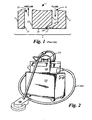
- Figure 1 is a cross-sectional view that illustrates one of four separate embodiments of the cleaning head disclosed in U.S. Pat. No. 6,243,914 wherein the cleaning head 1 for applying cleaning fluid without the inherent problems of spray either escaping or unduly penetrating the carpeting.
- Front and back surfaces 3, 5 of the cleaning head 1 combine with opposing end panels (not shown) to define a rectangular lip 7 which defines a surface contact area of the surface to be cleaned, which is momentarily subjected to the cleaning environment generated by the cleaning head 1.
- Securely mounted to an interior portion of the cleaning head 1 is a downwardly open fluid supply chamber 9 formed between a first wall 11 terminating in a head surface 13 and a second wall 15 terminating in an inwardly turned foot 17.
- the fluid supply chamber 9 terminates in an angled slot or groove 19 adjacent to the head surface 13 and oriented at an obtuse angle thereto, i.e., an acute angle to the surface to be cleaned.
- Walls 21 and 23 combine with opposing end panels (not shown) to form a vacuum chamber 25 that is spaced away from the fluid supply chamber 9 by the width of the head surface 13.
- cleaning fluid is supplied in a steady stream downwardly through the fluid supply chamber 9 between the walls 11 and 15 and flows outwardly through the angled slot 19 past the foot 17 and is drawn in a sheet across the head surface 13 by a vacuum formed in the vacuum chamber 25, whereby it is applied uniformly to the carpeting or other surface to be cleaned.
- the fluid is removed from the cleaned surface by vacuum in the vacuum chamber 25.
- the utilization of a sheet of fluid which flows down the fluid supply chamber 9 and across the head surface 13 eliminates the cooling of the fluid that results from atomizing caused by prior art spray nozzles.
- the utilization of a sheet of fluid also reduces the amount of fluid being used for a given cleaning job, and eliminates over spray of the cleaning fluid should the cleaning head 1 be inadvertently moved from the surface to be cleaned or tilted so one edge is raised.
- the present invention provides improvements to the cleaning head disclosed in U.S. Pat. No. 6,243,914 .
- the present invention provides novel improvements on the cleaning head disclosed in U.S. Pat. No. 6,243,914 . Accordingly, the present invention provides an improved apparatus according to claim 1 for spraylessly delivering cleaning fluid for cleaning flooring surfaces, wall surfaces and upholstery.
- the apparatus and method of the invention is embodied in a novel three-part bar jet assembly formed of a substantially flat base plate having spaced apart and substantially parallel planar cleaning fluid input and output surfaces and an elongated cleaning fluid discharge chamber formed therein in communication with both the input and output surfaces, the discharge chamber having a relatively long and wide mouth or opening in communication with the fluid input surface and terminating adjacent to one side of the chamber in a relatively shorter and narrower discharge slot that is in communication with the fluid output surface; a forward or leading cover plate having spaced apart and substantially parallel planar mounting and cleaning fluid output surfaces that are interconnected along one edge by a substantially planar cleaning fluid retrieval slot surface that is oriented to form a right angle with both the mounting and output surfaces and along an opposite edge by a substantially planar discharge slot leading surface that is optionally oriented to form an obtuse angle to the leading cover plate output surface, the mounting surface of the leading cover plate is securely fixed to the output surface of the base plate with the discharge slot leading surface adjacent to and substantially contiguous with an
- the present invention is an apparatus for spraylessly delivering cleaning fluid for cleaning flooring surfaces, wall surfaces and upholstery.
- the apparatus of the invention being embodied, by example and without limitation, in a novel three-part bar jet assembly formed of a substantially flat base plate having spaced apart and substantially parallel planar cleaning fluid input and output surfaces and having an elongated cleaning fluid discharge chamber formed therein in communication with both the input and output surfaces, the discharge chamber having a relatively long and wide mouth or opening in communication with the fluid input surface and terminating adjacent to one side of the chamber in a relatively shorter and narrower discharge slot that is in communication with the fluid output surface; a forward or leading cover plate having spaced apart and substantially parallel planar mounting and cleaning fluid output surfaces that are interconnected along one edge by a substantially planar cleaning fluid retrieval slot surface that is oriented to form a right angle with both the mounting and output surfaces and along an opposite edge by a substantially planar discharge orifice leading surface that is optionally oriented to form an obtuse angle to the leading cover plate output surface, the mounting surface of the leading cover plate
- the acute angle formed by the narrow cleaning fluid discharge slot relative to the cleaning fluid output surfaces of the leading and following cover plates is on the order of 45 degrees or less. Furthermore, the discharge orifice leading and following surfaces are spaced apart by 0.020 inches or less to form the narrow and elongated cleaning fluid discharge slot.
- the cleaning fluid discharge chamber is formed in the base plate having a striker plate adjacent to the discharge slot.
- the striker plate is embodied as a substantially planar surface having one elongated edge that intersects the cleaning fluid input surface of the base plate and a second elongated edge that intersects one side of the discharge slot adjacent to the fluid output surface.
- An elongated upright wall portion of the fluid discharge chamber is formed between the cleaning fluid input surface of the base plate and the other side of the discharge slot opposite from the striker plate.
- the upright wall is oriented substantially at a right angle to the cleaning fluid input surface of the base plate, whereby the fluid discharge chamber is embodied in an elongated right triangular chamber having the upright right-angle wall between the base plate input and output surfaces on one side of the discharge slot, and the angled striker plate inclined between the base plate input and output surfaces on the other side of the discharge slot opposite from the upright right-angle wall.
- the discharge slot in the base plate is embodied in an elongated throat situated between the upright right-angle wall and the inclined striker plate surface, and communicating between the discharge chamber and the output surface of the base plate.
- the novel bar jet assembly of the invention is coupled to a cleaning surface of a rotary cleaning plate having a cleaning fluid and soil retrieval slot machined therethrough and being coupled to a vacuum source, the right-angled peripheral edge surface of the base plate and the retrieval slot surface of the leading cover plate both being positioned adjacent to and substantially contiguous with the retrieval slot machined in the rotary cleaning plate.
- the relatively long and wide input opening of the discharge chamber is coupled through the rotary cleaning plate to a source of pressurized cleaning fluid.
- the discharge chamber is coupled to a cleaning fluid distribution manifold that is further structured to operate as an expansion chamber for reducing the pressure of the cleaning fluid to below a delivery pressure provided by the source of pressurized cleaning fluid.
- the rotary cleaning plate includes a plurality of the cleaning fluid and soil retrieval slots machined therethrough and being coupled to the same or another vacuum source, and including a plurality of the novel bar jet assemblies with one of the bar jet assemblies being coupled to the rotary cleaning plate adjacent to each of the cleaning fluid and soil retrieval slots.
- a plurality of stabilizing members is distributed across the cleaning surface of the rotary cleaning plate with at least one of the stabilizer members positioned midway between each pair of the bar jet assemblies, whereby the cleaning surface of the rotary cleaning plate is maintained at a substantially constant and uniform height above or away from the carpeting or other surface to be cleaned.
- cleaning fluid distribution manifold includes a centrally located input sprue hole and expansion chamber coupled to a network of cleaning fluid distribution channels of combined area sufficiently enlarged relative to a cleaning fluid delivery tube as to significantly reduce the delivery pressure of the cleaning fluid at the input sprue hole to the expansion chamber.
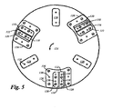
- FIG 2 is an exemplary illustration of a cleaning system 100 useful for operating the improved cleaning head of the present invention.
- the cleaning system 100 is, for example, embodied in a main waste receptacle 102 into which soiled fluid is returned via a vacuum hose 104 interconnected with the cleaning head 106 of the invention.
- the liquid cleaning fluid is supplied to the cleaning head 106 via a liquid cleaning fluid delivery tube 110 coupled to the source of pressurized liquid cleaning fluid. It is to be understood that this cleaning system could be track-mounted.
- FIG 3 is a cross-sectional view of the cleaning head 106 taken through the plan view of Figure 4 .
- the cleaning head includes a half funnel shaped liquid cleaning fluid discharge chamber 112 that is structured to be coupled to the cleaning system supply of cleaning fluid via a liquid cleaning fluid delivery slot 113, as discussed herein.
- the cleaning fluid discharge chamber 112 terminates in a parallel or an angled (shown) striker plate 114 that is adjacent to a perpendicular or an angled (shown) liquid cleaning fluid discharge slot or groove 116 opening onto one side of a cleaning head operating surface 118.
- a liquid cleaning fluid and soil retrieval slot retrieval slot or groove 120 Spaced away from the angled discharge orifice 116 across the expanse of the head operating surface 118 is a liquid cleaning fluid and soil retrieval slot retrieval slot or groove 120 coupled to a vacuum chamber 121 that is structured to be coupled to the cleaning system vacuum source.
- the cleaning fluid and soil retrieval slot 120 is formed in part by a liquid cleaning fluid retrieval slot surface 123 that is oriented crosswise to the cleaning head operating surface 118.
- the cleaning fluid enters the discharge chamber 112 in the cleaning head 106 in a steady stream and impacts against the angled striker plate 114 adjacent to the discharge orifice 116. Impact against the angled striker plate 114 forms the cleaning fluid into a substantially uniform thin sheet that flows out of the discharge chamber 112 onto the cleaning head operating surface 118 through the angled discharge orifice 116. As indicated by the arrow, the substantially uniform thin sheet of cleaning fluid is drawn across the operating surface 118 and into the retrieval slot 120 and vacuum chamber 121 by a vacuum formed therein for delivery to the waste receptacle 102 via the vacuum hose 104.
- the cleaning fluid discharge chamber 112, the angled striker plate 114 and discharge slot or groove 116, and the operating surface 118 are embodied in a bar jet assembly 122 that is structured for substantially permanent attachment to a bottom cleaning surface of a substantially circular rotary cleaning plate 124 that is coupled for high speed rotary motion relative to the cleaning head 106.
- the bar jet assembly 122 is optionally embedded or otherwise supported by a shoe 126, shown more clearly in a subsequent Figure, that has about the same thickness as the bar jet assembly 122 and is fixed to the surface of the cleaning plate in a manner that provides a lead-in for protecting the carpeting or other surface to be cleaned from damage by impact with the leading edge of the bar jet assembly 122.
- the rotary cleaning plate 124 includes the retrieval slot 120 which is machined therethrough and is positioned adjacent a forward edge of the cleaning head operating surface 118 opposite from the discharge orifice 116, where the forward edge is leading when the rotary cleaning plate 124 rotates about its center in the direction that the thin sheet of cleaning fluid is drawn across the operating surface 118, as indicated by the arrow and by the rotational arrow shown in Figure 5 .
- the bar jet assembly 122 is repeated in a plurality of bar jet assemblies 122 distributed evenly across the bottom cleaning surface of the cleaning plate 124.
- the plurality of distributed bar jet assemblies 122 are optionally interspersed with one or more stabilizers 128 also having the lead-in feature described herein.
- the stabilizers 128 are, by example and without limitation, formed of a slick nylon or Teflon material to better slide without sticking across the surface to be cleaned.
- Figure 4 is a top down or plan view of the cleaning head 106 of the invention that illustrates the distributed flow channels of the liquid cleaning fluid into a central sprue hole 130 and expansion chamber 131 in a liquid cleaning fluid distribution manifold 132 and thence outward along closed liquid cleaning fluid distribution channels 134, the expansion chamber 131 and cleaning fluid distribution channels 134 being of substantially greater area than an inlet which causes the distribution manifold 132 to further operate as an expansion chamber for reducing the pressure of the cleaning fluid to below the delivery pressure provided by the pressurized source 108.
- another portion of the cleaning head 106 operates as the expansion chamber without limiting the scope of the invention as such devices are well-known in the art.
- the cleaning fluid is delivered under reduced pressure to each of the plurality of bar jet assembly 122 positioned at the outermost radial extent of the different cleaning fluid flow distribution channels 134 adjacent to the periphery of the rotary cleaning plate 124.
- the cleaning fluid flow distribution channels 134 are formed in communication with the cleaning fluid delivery slot 113 opening in the rotary cleaning plate 124 positioned at least adjacent to and preferably contiguous with or overlapping the cleaning fluid discharge chamber 112 of the corresponding bar jet assembly 122 such that the cleaning fluid naturally enters the discharge chamber 112 through the delivery slot 113.
- Figure 5 is a bottom plan view of the cleaning surface of the rotary cleaning plate 124 having a plurality of the bar jet assemblies 122 and the stabilizers 128 fixed thereto in a uniformly distributed manner with each of the bar jet assemblies 122 being embedded in one of the shoes 126.
- the bar jet assemblies 122 and stabilizers 128 are each fixed to the cleaning surface of the rotary cleaning plate 124 by one or more threaded fasteners 136 screwed into threaded holes in the rotary cleaning plate 124.
- At least the bar jet assemblies 122 are accurately positioned relative to the corresponding cleaning fluid flow distribution channels 134 by means of the threaded fasteners 136 being embodied as flathead fasteners fitted into counter-sunk holes machined in the bar jet assemblies 122.
- Use of flathead fasteners in counter-sunk holes also causes the bar jet assemblies 122 to present a flush surface to the carpeting or other surface to be cleaned.
- the bar jet assemblies 122 present the corresponding cleaning fluid discharge and retrieval slots 116, 120 and the cleaning head operating surfaces 118 positioned therebetween.
- One of the shoes 126 is fitted around each of the bar jet assemblies 122 and secured to the cleaning surface of the rotary cleaning plate 124 by one or more of the threaded fasteners 136.
- the shoes 126 are additionally more accurately positioned by means of one or more locating pins 138 communicating between each of the shoes 126 and the rotary cleaning plate 124.
- Figures 6, 7, 8 and 9 illustrate one embodiment of the bar jet assembly 122 of the invention, wherein Figure 6 is a top plan view looking at a cleaning fluid input face 140 of the bar jet assembly 122, Figure 7 is an end view taken from Figure 6, Figure 8 is a cross-sectional view taken through the top plan view of Figure 6, and Figure 9 is a bottom plan view looking at the operational cleaning face of the bar jet assembly 122.
- the cleaning fluid input face 140 of the bar jet assembly 122 is a planar surface embodied as a flat aluminum or aluminum alloy base plate 142, by example and without limitation of about 3mm (1/8 inch)thickness, which is structured for mounting and sealing to the cleaning surface of the rotary cleaning plate 124 by one or more of the threaded fasteners 136 shown in Figure 5 .
- the cleaning fluid discharge chamber 112 is open and exposed for connection to the cleaning fluid distribution channel 134 of the distribution manifold 132 shown in Figure 4 .
- the cleaning fluid discharge chamber 112 is closed on opposite ends and includes the angled striker plate 114 leading from the fluid input face 140 to the angled discharge orifice 116 opening onto the cleaning head operating surface 118 (shown in Figures 7, 8, 9 ).
- An upright wall 144 of the fluid discharge chamber 112 across the angled discharge orifice 116 from the angled striker plate 114 is provided substantially perpendicular to the fluid input face 140 of the bar jet assembly 122.
- one or more of the more locating pins 138 are provided for locating a pair of corrosion resistant or stainless steel cover plates 146, 148 (shown in Figures 7, 8, 9 ) of the bar jet assembly 122 relative to a cleaning fluid output surface 150 of the base plate 142 which has the cleaning fluid discharge chamber 112 formed therein.
- Corrosion resistant or stainless steel is used because it is tough and durable under extreme conditions and holds both an edge and a surface finish, all of which are characteristics desirable in surface cleaning equipment of the type recited here.
- the pins 138 are optionally press-fit in the base plate 142 and each of the cover plates 146, 148 for securing the bar jet assembly 122.
- the pins 138 are embodied as rivets for both locating the cover plates 146, 148 and for securing the bar jet assembly 122.
- One or more fastener through holes 152 are machined in the base plate 142 of the bar jet assembly 122 on either side of the cleaning fluid discharge chamber 112 for securing the bar jet assembly 122 to the cleaning surface of the rotary cleaning plate 124 by one or more of the threaded fasteners 136.
- Figure 7 is the end view of the bar jet assembly 122 illustrating each of the two cover plates 146, 148 secured to the base plate 142.
- the two cover plates 146, 148 are each machined with one of two surface 154, 156 of the angled discharge slot or groove 116 that opens onto one side of the operating surface 118.
- the two surfaces 154, 156 of the discharge orifice 116 each form an obtuse angle of 45 degrees or more as measured from the upright wall 144 of the fluid discharge chamber 112, i.e., an obtuse angle relative to the cleaning surface of the rotary cleaning plate 124 (shown in phantom).
- the angularity of the discharge orifice 116 is effective for reducing the tendency of the pressurized cleaning fluid to penetrate deep into the carpeting to be cleaned.
- the angle of the discharge orifice 116 causes the cleaning fluid to remain near the surface of the carpet so that the vacuum source more efficiently withdraws the cleaning fluid from the carpet nap and pulls it across the cleaning head operating surface 118. Because the cleaning fluid remains near the surface of the nap, the carpet dries very rapidly, being almost dry to the touch immediately following passage of the cleaning head 106. In contrast, a more upright or vertical discharge slot causes the cleaning fluid to be driven comparatively more deeply into the nap, and the carpet requires comparatively longer to dry.
- the discharge orifice 116 is oriented at about 45 degrees which minimizes any tendency for the trailing edge of the slot 116 to snag on the carpeting or other surface to be cleaned.
- the two discharge slot surfaces 154, 156 are oriented at substantially the same angle relative to the upright wall 144 or the cleaning surface of the rotary cleaning plate 124, i.e., the two discharge slot surfaces 154, 156 are substantially mutually parallel. Parallelism of the discharge slot surfaces 154, 156 enhances the formation of the uniform sheet of liquid cleaning fluid. Furthermore, the two discharge slot surfaces 154, 156 are spaced only a short distance apart so that the discharge orifice 116 is very narrow which also enhances the formation of the uniform sheet of liquid cleaning fluid.
- the two discharge slot surfaces 154, 156 are spaced apart on the order of about 0,2 to 0,25 mm (8 to 10 thousands of an inch) or less such that the discharge orifice 116 is on the order of about 0,2 to 0,25 mm (0.008 inch to 0.010 inch) or less in width.
- the inventor has determined that widths of 0.25 to 0,43 mm (0.010 inch to about 0.017 inch) or even as much as 0.5mm (0.020 inch) for the discharge orifice 116 are also effective for forming the uniform sheet of liquid cleaning fluid.
- the width of the discharge orifice 116 is limited to the degree that sufficient back pressure is developed in the discharge chamber 112 so that the cleaning fluid is discharge from the slot 116 under pressure, rather than flowing freely from the discharge orifice 116.
- the cleaning fluid retrieval slot surface 123 is a substantially planar surface that is oriented to form a right angle with cleaning head operating surface 118.
- Figure 8 is the cross-sectional view taken through the top plan view of Figure 6 and illustrates the fluid discharge chamber 112 being formed as a reservoir for a quantity of liquid cleaning fluid.
- the fluid discharge chamber 112 is of sufficient volume to equalize the fluid pressure across the entire length of the discharge orifice 116 such that a the cleaning fluid is fed to the slot 116 at a substantially uniform rate, whereby the cleaning fluid is discharged from the slot 116 in a substantially uniform sheet of liquid.
- the fluid discharge chamber 112 is formed of the angled striker plate 114 and the upright wall 144 and terminating in the angled discharge orifice 116.
- the striker plate 114 forms an obtuse angle of 45 degrees to 60 degrees or more as measured from the upright wall 144 of the fluid discharge chamber 112, i.e., an obtuse angle relative to the cleaning surface of the rotary cleaning plate 124 which is represented by the fluid input face 140 of the bar jet assembly 122. Effectiveness of the cleaning head 106 is enhanced when the striker plate 114 is closer to being parallel with the cleaning surface of the rotary cleaning plate 124, rather than perpendicular thereto.
- the striker plate 114 forms an obtuse angle of 60 to 75 degrees or more with the upright wall 144 of the fluid discharge chamber 112.
- throat 158 measures about the same as the width of the discharge orifice 116, but may be wider, e.g., up to about 0.2 to about 0.43 mm (0.008 to about 0.017 inch) or even as much as 0,5mm (0.020 inch) or more in width, and extends most of the length of the fluid discharge chamber 112.
- the throat 158 communicates between the fluid discharge chamber 112 of the base plate 142 and the angled discharge orifice 116.
- the leading discharge slot surface 156 which is formed in the leading cover plate 148, is aligned with the wall of throat 158 that is formed by the upright wall 144 portion of the fluid discharge chamber 112, and the trailing discharge slot surface 154, which is formed in the trailing cover plate 146, is aligned with the wall of the throat 158 adjacent to the angled striker plate 114.
- cleaning fluid entering the fluid discharge chamber 112 must impact with the angled striker plate 114 whereby it is formed into a substantially uniform sheet of cleaning fluid before exiting the discharge chamber 112 through the discharge orifice 116 and the intervening throat 158, if present.
- Figure 9 is an bottom view of the bar jet assembly 122 showing the operational surface thereof and illustrating each of the two cover plates 146, 148 secured to the base plate 142 with one or more of the press-fit pins 138 and machined with one or more counter-sunk through holes 160 for securing the bar jet assembly 122 to the cleaning surface of the rotary cleaning plate 124 by one or more of the threaded fasteners 136.
- Figure 9 also illustrates that, according to one embodiment of the invention, the portion of the discharge orifice 116 formed between the two cover plates 146, 148 extends the entire length of the bar jet assembly 122, while the portion of the discharge orifice 116 formed in the base plate 142 by the throat 158 is truncated at both ends before reaching the ends of the bar jet assembly 122.
- Figure 10 is a plan view of the shoe 126 (shown in Figures 3 , 5 ) in which the bar jet assembly 122 is optionally embedded or otherwise supported.
- the shoe 126 is embodied with one or more of the counter-sunk through holes 160 for securing it to the cleaning surface of the rotary cleaning plate 124 by one or more of the threaded fasteners 136, as illustrated in Figure 5 .
- the shoe 126 may also includes one or more pin holes 162 each structured to accept one of the locating pins 138 for accurately positioning the shoe 126 relative to the rotary cleaning plate 124.
- An outer or peripheral edge 164 of the shoe 126 is optionally contoured to match the rotary cleaning plate 124 and as such can be located adjacent the peripheral edge of the rotary cleaning plate 124, as illustrated in Figure 5 .
- the shoe 126 is formed with an aperture 166 having an inner peripheral contour 168 matched to the outer peripheral contour 170 (shown in Figure 9 ) of the bar jet assembly 122, except at an open edge portion 172 delineated by the phantom line 174.
- the open edge portion 172 is positioned to correspond to the retrieval slot or groove 120 in the rotary cleaning plate 124 adjacent to the cleaning head operating surface 118 opposite the discharge orifice 116.
- the open edge portion 172 thus operates as an extension to the rotary cleaning plate 124 that moves the operational cleaning surface toward the carpeting or other surface to be cleaned and thereby operates as a "skirt" to enhance the vacuum generated at the inlet to the retrieval slot 120 by shielding the slot 120 from the ambient environment.
- the delineation indicated by the phantom line 174 coincides with the cleaning fluid retrieval slot surface 123 of the bar jet assembly such that the open edge portion 172 is optionally sized substantially identically to the retrieval slot 120.
- Figures 11 and 12 are top and bottom plan views, respectively, of the base plate 142 portion of the bar jet assembly 122.
- Figure 11 illustrates the fluid discharge chamber 112 of the base plate 142 being formed between the upright wall 144 and an edge 176 where the angled striker plate 114 intersects the cleaning fluid input face 140 opposite from the throat 158 to the cleaning fluid output surface 150.
- the fluid discharge chamber 112 is bounded by end walls 178, 180 that communicate between the angled striker plate 114 and the cleaning fluid input face 140.
- the throat 158 through which the cleaning fluid exits the discharge chamber 112 and enters the discharge orifice 116 is bounded on both ends opposing throat walls 182, 184.
- the base plate 142 is embodied by example and without limitation in a sheet of aluminum or aluminum alloy for ease of machining, the material stock being about 3,18mm (1/8 inch) thickness with overall outside dimensions of about 34,9 mm (1-3/8 inch) to about 36,5 mm (1-7/16 inch) width by about 57,2 mm (2-1/4 inch) to about 63,5 mm (2-1/2 inch) length.
- Figures 13 and 14 are plan and end views, respectively, of the forward cover plate 148 embodying the cleaning head operating surface 118.
- Figure 14 particularly illustrates the leading discharge slot surface 156 which is aligned with the wall of throat 158 in the fluid discharge chamber 112.
- the leading discharge slot surface 156 is oriented at an obtuse angle a of 45 degrees or more to a perpendicular to a substantially planar mounting surface 186 by which the forward cover plate 148 is mounted to the base plate 142 in the bare jet assembly 122.
- the leading discharge slot surface 156 is oriented at an angle of 135 degrees or more from the mounting surface 186.
- the mounting surface 186 and the cleaning head operating surface 118 are spaced-apart and mutually parallel surfaces that are interconnected along one edge by the cleaning fluid retrieval slot surface 123 that is embodied as a substantially planar surface oriented to form a right angle with both the mounting surface 186 and the operating surface 118.
- the cleaning fluid retrieval slot surface 123 forms one portion of the cleaning fluid and soil retrieval slot or groove 120, as illustrated in Figures 3 and 17 .
- the forward cover plate 148 is embodied by example and without limitation in a sheet of corrosion resistant steel about 1,59 mm (1/16 inch) thickness with overall outside dimensions of about 15,9mm (5/8 inch) to about 19,1mm (3/4 inch) width by about 57,2 mm (2-1/4 inch) to about 63,5 mm (2-1/2 inch) length.
- the cleaning head operating surface 118 is provided with a very smooth finish such that carpeting and other materials and surfaces are not materially damaged by contact with the operating surface 118.
- Figures 15 and 16 are plan and end views, respectively, of the aft or following cover plate 146 having the following discharge slot surface 154 embodied therein and oriented at substantially the same obtuse angle a of 45 degrees or more to a perpendicular to a substantially planar mounting surface 188 by which the following cover plate 146 is mounted to the base plate 142 in the bare jet assembly 122.
- the following cover plate 146 is also provided with a substantially planar skid surface 190 that is spaced away from and mutually parallel with the mounting surface 188.
- the cleaning head 106 rests on the skid surface 190 during operation for maintaining the head 106 parallel with the carpeting or other surface to be cleaned and for maintaining the vacuum at the cleaning fluid and soil retrieval slot 120.
- the following cover plate 146 is embodied by example and without limitation in a sheet of corrosion resistant steel about 1,59mm (1/16 inch) thickness with overall outside dimensions of about 19,1mm (3/4 inch) width by about 57,2mm (2-1/4 inch) to about 63,5mm (2-1/2 inch) length.
- the cleaning head skid surface 190 is provided with a very smooth finish such that carpeting and other materials and surfaces are not materially damaged by contact with the skid surface 190.
- Figures 13 and 15 also illustrate the plurality of pin holes 162 each structured to accept one of the locating pins 138 for accurately locating the respective leading and following coyer plates 148, 146 on the base plate 142 and relative to one another such that the respective leading and following discharge slot surfaces 156, 154 are substantially parallel and spaced apart to form the narrow discharge orifice 116 described herein.
- the leading and following cover plates 148, 146 are also shown in Figures 13 and 15 to be formed with a plurality of the counter-sunk through holes 160 for securing the bar jet assembly 122 to the cleaning surface of the rotary cleaning plate 124 by one or more of the threaded fasteners 136 as discussed herein.
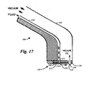
- FIG 17 illustrates one alternative embodiment of the cleaning head 106 of the invention wherein a single bar jet assembly 122 of the invention is coupled to a hand-held wand having a nozzle 192 having the half-funnel shaped cleaning fluid discharge chamber 112 coupled to the cleaning fluid source via a feed tube 194 for delivering liquid cleaning fluid.
- the feed tube 194 is structured for being coupled to the source of pressurized liquid cleaning fluid via the cleaning fluid delivery tube 110 (shown in Figure 2 ).
- the cleaning fluid discharge chamber 112 again terminates in the angled striker plate 114 that is adjacent to the angled discharge slot or groove 116 opening onto one side of the cleaning head operating surface 118.
- the cleaning fluid and soil retrieval slot or groove 120 formed in part by the cleaning fluid retrieval slot surface 123 and coupled to the vacuum chamber 121 that is constructed in the cleaning head 106.
- the vacuum chamber 121 is structured to be coupled to the cleaning system vacuum source via the vacuum hose 104.
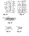
- Figures 18, 19 and 20 illustrate one alternative embodiment of the bar jet assembly 122 of the invention, wherein Figure 18 is a top plan view looking at the cleaning fluid input face 140 of the alternative bar jet assembly 122, Figure 19 is a bottom plan view looking at the operational cleaning face of the alternative bar jet assembly 122, and Figure 19 is a cross-sectional view of the alternative bar jet assembly 122 taken through the top plan view of Figure 18 .
- the cleaning fluid input face 140 of the bar jet assembly 122 is a planar surface embodied as the flat aluminum or aluminum alloy base plate 142 which is structured for mounting and sealing to the cleaning surface of the rotary cleaning plate 124 by the threaded fasteners 136 shown in Figure 5 .
- the cleaning fluid discharge chamber 112 is open and exposed for connection to the cleaning fluid distribution channel 134 of the distribution manifold 132 shown in Figure 4 .
- the cleaning fluid discharge chamber 112 is a box-shaped space formed by a substantially rectangular aperture in the base plate 142 and substantially closed on its output surface by the striker plate 114 formed substantially perpendicular to the cleaning fluid input face 140 such that the cleaning fluid discharge chamber 112 is shown in Figure 20 to have a substantially rectangular cross-section.
- the throat 158 of the discharge chamber 112 is eliminated with the discharge orifice 116 opening onto the cleaning head operating surface 118 along one edge adjacent to the upright wall 144 (shown in Figures 19, 20 ), such that the discharge orifice 116 communicates directly between the fluid discharge chamber 112 and the operating surface 118.
- the discharge orifice 116 is a formed between the machined surfaces 154, 156 (shown more clearly in Figures 21, 22 ) of the two cover plates 146, 148, with the discharge orifice 116 being provided substantially crosswise or perpendicular to the fluid input face 140 of the bar jet assembly 122.
- one or more of the more locating pins 138 are provided for locating the pair of corrosion resistant or stainless steel cover plates 146, 148 (shown in Figures 19, 20 ) of the bar jet assembly 122 relative to the cleaning fluid output surface 150 of the base plate 142 which has the cleaning fluid discharge chamber 112 formed therein.
- One or more of the fastener through holes 152 are machined in the base plate 142 on either side of the cleaning fluid discharge chamber 112 for securing the bar jet assembly 122 to the cleaning surface of the rotary cleaning plate 124 by one or more of the threaded fasteners 136.
- the two surfaces 154, 156 of the discharge orifice 116 are both upright or even perpendicular relative to the cleaning surface of the rotary cleaning plate 124 (shown in phantom). While effectiveness of the cleaning head 106 in reducing cleaning fluid penetration is enhanced when the discharge orifice 116 is closer to parallel with the cleaning surface of the rotary cleaning plate 124, the cleaning head 106 is alternatively oriented perpendicular thereto.
- the two discharge slot surfaces 154, 156 are oriented substantially parallel to one another and spaced only a short distance apart so that the discharge orifice 116 is very narrow, as discussed herein.
- the cleaning fluid retrieval slot surface 123 is a substantially planar surface that is oriented to form a right angle with cleaning head operating surface 118.
- Figure 19 is an bottom view of the bar jet assembly 122 showing the operational surface thereof and illustrating each of the two cover plates 146, 148 secured to the base plate 142 with one or more of the press-fit pins 138 and machined with one or more of the counter-sunk through holes 160 for securing the bar jet assembly 122 to the cleaning surface of the rotary cleaning plate 124 by one or more of the threaded fasteners 136.
- Figure 19 also illustrates that, according to one embodiment of the invention, the portion of the discharge orifice 116 formed between the two cover plates 146, 148 extends the entire length of the bar jet assembly 122, while the discharge chamber 112 is truncated at both ends without extending to the ends of the bar jet assembly 122.
- Figure 20 is the cross-sectional view taken through the top plan view of Figure 18 and illustrates the fluid discharge chamber 112 being formed of the crosswise striker plate 114 and the upright wall 144 and terminating in the upright discharge orifice 116.
- the leading discharge slot surface 156 which is formed in the leading cover plate 148, is aligned with the upright wall 144 portion of the fluid discharge chamber 112, and the trailing discharge slot surface 154, which is formed in the trailing cover plate 146, is spaced behind the leading discharge slot surface 156.
- cleaning fluid entering the fluid discharge chamber 112 must impact with the striker plate 114 before exiting the discharge chamber 112 through the discharge orifice 116 under pressure.
- Figures 21 and 22 are end views, respectively, of the forward or leading cover plate 148 and the aft or following cover plate 146 according to the alternative embodiment of the invention illustrated in Figures 18, 19, 20 .
- the leading discharge slot surface 156 of the leading cover plate 148 is illustrated in Figure 21 as being oriented at a substantially right angle b or perpendicular to the substantially planar mounting surface 186 by which the forward cover plate 148 is mounted to the base plate 142 in the bare jet assembly 122.
- the leading discharge slot surface 156 is oriented at an angle of about 90 degrees from the mounting surface 186.
- the cleaning fluid retrieval slot surface 123 that forms one portion of the cleaning fluid and soil retrieval slot or groove 120 is embodied as the substantially planar surface oriented to form a right angle with both the mounting surface 186 and the operating surface 118.
- Figure 22 illustrates the following discharge slot surface 154 of the following cover plate 146 as being oriented at the substantially right angle b or perpendicular to the substantially planar mounting surface 188 by which the following cover plate 146 is mounted to the base plate 142 in the bare jet assembly 122.
- the following discharge slot surface 154 is oriented at an angle of about 90 degrees from the mounting surface 188.
- the following cover plate 146 is also provided with the substantially planar skid surface 190 that is spaced away from and mutually parallel with the mounting surface 188.
- the cleaning head 106 rests on the skid surface 190 during operation for maintaining the head 106 parallel with the carpeting or other surface to be cleaned and for maintaining the vacuum at the cleaning fluid and soil retrieval slot 120.
- Figures 23, 24, 25 and 26 illustrate another alternative embodiment of the bar jet assembly 122 of the invention, wherein Figure 23 is a top plan view looking at the cleaning fluid input face 140 of the alternative bar jet assembly 122, Figure 24 is a bottom plan view looking at the operational cleaning face of the alternative bar jet assembly 122, and Figures 25 and 26 are alternative cross-sectional views of the alternative bar jet assembly 122 taken through the top plan view of Figure 23 .
- the discharge orifice 116 is embodied as a substantially linear pattern of multiple discharge slots 196 formed, by example and without limitation, as a line of discharge slots 196 communicating between one the discharge chamber 112 and the operating surface 118.
- the multiple discharge slots 196 are cut about 0,2 to 0,25 mm (8 to 10 thousands of an inch) or less deep such that each discharge slot 196 is on the order of about 0.7mm (0.008 inch) to 0,25 mm (0.010 inch) or less in depth.
- discharge slots 196 alternatively cut 0,25 mm (0.010 inch) to about 0,43 mm (0.017 inch) in depth or even as much as 0,5 mm (0.020 inch) in depth are also effective for forming the uniform sheet of liquid cleaning fluid according to the invention.
- the depth of the discharge slots 196 is limited to the degree that sufficient back pressure is developed in the discharge chamber 112 so that the cleaning fluid is discharge from the accumulated slots 196 under pressure, rather than flowing freely from the discharge slots 196.
- the length of the discharge slots 196 as measured along the discharge slot surfaces 154, 156 can be varied from the minimum slot width of about 0,2 mm (0.008 inch) to as much as the entire length of the discharge chamber 112, without materially affecting the practice of the invention. Spacing between the individual discharge slots 196 can be varied from very close to widely spaced, without materially affecting the practice of the invention, as long as sufficient liquid cleaning fluid volume is discharged through the discharge slots 196 to form a substantially uniform sheet of liquid across a major portion of the operating surface 118 of the leading cover plate 148.
- the discharge slots 196 are formed along the leading edge of the discharge chamber 112 adjacent to the leading upright wall 144.
- the pattern of discharge holes 196 is alternatively formed adjacent a trailing edge 198 of the discharge chamber 112, or alternatively, between the leading and trailing edges 144, 198 without materially affecting the practice of the invention.
- the pattern of discharge slots 196 is formed, by example and without limitation, spaced apart as by comb teeth along the leading edge 154 of the trailing or following cover plate 146, or alternatively, along the trailing edge 156 of the leading cover plate 148.
- the pattern of discharge slots 196 that form the discharge orifice 116 are formed crosswise or substantially perpendicular to the operating surface 118 as described in connection with the embodiment of Figures 18-22 .
- the pattern of discharge slots 196 that form the discharge orifice 116 are formed at angle to the operating surface 118 as described in connection with the embodiment of Figures 6-9 .
- the cleaning fluid discharge chamber 112 is substantially closed on its output surface by the striker plate 114 which is either the angled striker plate illustrated in Figure 3 , or the crosswise striker plate illustrated in Figure 20 , without materially affecting the practice of the invention.
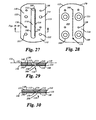
- Figures 27, 28, 29 and 30 illustrate another alternative embodiment of the bar jet assembly 122 of the invention, wherein Figure 27 is a top plan view looking at the cleaning fluid input face 140 of the alternative bar jet assembly 122, Figure 28 is a bottom plan view looking at the operational cleaning face of the alternative bar jet assembly 122, and Figures 29 and 30 are alternative cross-sectional views of the alternative bar jet assembly 122 taken through the top plan view of Figure 27 .
- the discharge orifice 116 is embodied as a substantially linear pattern of discharge apertures or holes 200 formed, by example and without limitation as a line of substantially round discharge holes 200 communicating as by drilling between one the discharge chamber 112 and the operating surface 118.
- the discharge holes 200 are formed along the leading edge of the discharge chamber 112 adjacent to the leading upright wall 144.
- the pattern of discharge holes 196 is alternatively formed adjacent the trailing edge 198 of the discharge chamber 112, or alternatively, between the leading and trailing edges 144, 198 without materially affecting the practice of the invention.
- the discharge holes 200 are sized to discharge a sufficient liquid cleaning fluid volume through the pattern of discharge holes 200 to form a substantially uniform sheet of liquid across a major portion of the operating surface 118.
- the multiple discharge holes 200 are about 0,2 to 0,25 mm (8 to 10 thousands of an inch) or less in diameter.
- discharge holes 200 alternatively made 0,25 mm (0.010 inch) to about 0,43 mm (0.017 inch) in diameter or even as much as 0,5 mm (0.020 inch) diameter are also effective for forming the uniform sheet of liquid cleaning fluid according to the invention.
- the diameter of the discharge holes 200 is limited to the degree that sufficient back pressure is developed in the discharge chamber 112 so that the cleaning fluid is discharge from the accumulated holes 200 under pressure, rather than flowing freely from the discharge holes 200.
- the length of the pattern of discharge holes 200 is optionally as much as the entire length of the discharge chamber 112.
- Spacing between adjacent holes 200 can be varied from very close to widely spaced, without materially affecting the practice of the invention, as long as sufficient liquid cleaning fluid volume is discharged through the discharge slots 196 to form a substantially uniform sheet of liquid across a major portion of the operating surface 118.
- the pattern of discharge holes 200 forming the discharge orifice 116 is formed in the leading edge 154 of the trailing or following cover plate 146, or alternatively, along the trailing edge 156 of the leading cover plate 148.
- the pair of leading and trailing cover plates 146, 148 is replaced with a single corrosion resistant or stainless steel cover plate 202, as illustrated in Figure 28 , having formed therethrough the pattern of discharge holes 200 forming the discharge orifice 116 of the invention.
- the pattern of discharge holes 200 that form the discharge orifice 116 are formed crosswise or substantially perpendicular to the operating surface 118 as described in connection with the embodiment of Figures 18-22 .
- the pattern of discharge holes 200 that form the discharge orifice 116 are formed at angle to the operating surface 118 as described in connection with the embodiment of Figures 6-9 .
- the cleaning fluid discharge chamber 112 is substantially closed on its output surface by the striker plate 114 which is either the angled striker plate illustrated in Figure 3 , or the crosswise striker plate illustrated in Figure 20 , without materially affecting the practice of the invention.
Landscapes
- Cleaning By Liquid Or Steam (AREA)
- Nozzles (AREA)
- Detergent Compositions (AREA)
- Electrostatic Separation (AREA)
Claims (10)
- Balkenstrahlvorrichtung (122), gekennzeichnet durch:eine Grundplatte (142) mit für eine Reinigungsflüssigkeit einander gegenüberliegenden Eintritts- und Austrittsoberflächen (140, 150) mit einer länglichen in der Grundplatte (142) geformten Ausflusskammer (112) für die Reinigungsflüssigkeit, wobei die Ausflusskammer (112) mit der Eintrittsoberfläche (140) und der Austrittsoberfläche (150) für die Reinigungsflüssigkeit in Kontakt steht;eine oder mehrere Abdeckplatten (146, 148), die mit der Flüssigkeitsaustrittsoberfläche (150) der Grundplatte (142) verbunden sind;eine Austrittsöffnung (116) für die Reinigungsflüssigkeit, die durch die eine oder mehrere Abdeckplatten (146, 148) ausgebildet ist und mit der Ausflusskammer (112) der Reinigungsflüssigkeit in Kontakt steht;eine Betriebsoberfläche (118) des Reinigungskopfes, die gegenüberliegend zur Grundplatte (142) und angrenzend an die Austrittsöffnung (116) für die Reinigungsflüssigkeit ausgebildet ist;eine Gleitfläche (190), die durch eine der Abdeckplatten (146, 148) auf der relativ zur Betriebsoberfläche (118) gegenüberliegenden Seite der Austrittsöffnung (116) für die Reinigungsflüssigkeit ausgebildet ist; undeine Oberfläche (123) für einen Rückführungsschlitz für die Reinigungsflüssigkeit, der durch eine oder mehrere Abdeckplatten (146, 148) ausgebildet ist und durch die Betriebsoberfläche (118) des Reinigungskopfes von der Austrittsöffnung (116) der Reinigungsflüssigkeit beabstandet ist.
- Balkenstrahlvorrichtung nach Anspruch 1, dadurch gekennzeichnet, dass die eine oder mehreren Abdeckplatten (146, 148) zwei Abdeckplatten (146, 148) beinhalten.
- Balkenstrahlvorrichtung nach Anspruch 1, dadurch gekennzeichnet, dass die Austrittsöffnung (116) für die Reinigungsflüssigkeit, die durch eine oder mehrere Abdeckplatten (146, 148) ausgebildet ist, eine Austrittsöffnung (116) für die Reinigungsflüssigkeit beinhaltet, die relativ zur Betriebsoberfläche (118) des Reinigungskopfes abgewinkelt ist.
- Balkenstrahlvorrichtung nach Anspruch 3, dadurch gekennzeichnet, dass die abgewinkelte Austrittsöffnung (116) für die Reinigungsflüssigkeit ein zwischen zwei aneinandergrenzenden Abdeckplatten (146, 148) ausgebildeter, mit der Betriebsoberfläche (118) des Reinigungskopfes einen stumpfen Winkel (a) einschließender Schlitz ist.
- Balkenstrahlvorrichtung nach Anspruch 1, dadurch gekennzeichnet, dass die längliche Ausflusskammer (112) für die Reinigungsflüssigkeit einen im Wesentlichen dreieckigen Querschnitt aufweist mit einer Basis, die durch eine längliche, in Kontakt mit der Flüssigkeitseintrittsoberfläche (140) der Grundplatte stehende Öffnung ausgebildet ist und einem Scheitelpunkt, der durch den mit der Flüssigkeitsaustrittsoberfläche (150) der Grundplatte in Kontakt stehenden Auslassschlitz (158) ausgebildet ist.
- Balkenstrahlvorrichtung nach Anspruch 5, dadurch gekennzeichnet, dass der im Wesentlichen dreieckige Querschnitt der länglichen dreieckigen Auslasskammer (112) einen rechtwinkeligen Querschnitt mit einer durch die Grundplatte (142) ausgebildeten, aufrecht stehenden und senkrecht zur Flüssigkeitseintrittsoberfläche (140) orientierten Wand (144) ausbildet und sich zwischen der Eintrittsoberfläche (140) der Flüssigkeit und dem Auslassschlitz (158) in der Austrittsoberfläche (150) für die Reinigungsflüssigkeit erstreckt.
- Balkenstrahlvorrichtung nach Anspruch 6, dadurch gekennzeichnet, dass die längliche, dreieckige Ausflusskammer (112) eine angewinkelte Schlussplatte (114) für die Reinigungsflüssigkeit umfasst, die gegenüberliegend zur aufrecht stehenden Wand (144) mit einem Winkel zur Flüssigkeitseintrittsoberfläche (140) der Grundplatte orientiert ist und in Kontakt mit der Flüssigkeitseintrittsoberfläche (140) der Grundplatte und dem Auslassschlitz (158) der Grundplatte steht.
- Balkenstrahlvorrichtung nach Anspruch 7, dadurch gekennzeichnet, dass die Grundplatte (142) eine schmale längliche Verengung (158) umfasst, die mit der Ausflusskammer (112) der Grundplatte und der Austrittsoberfläche (150) für die Reinigungsflüssigkeit in Kontakt steht.
- Balkenstrahlvorrichtung nach Anspruch 1, dadurch gekennzeichnet, dass die Austrittsöffnung (116) für die Reinigungsflüssigkeit durch eine Vielzahl an Austrittsschlitzen (196) ausgebildet ist.
- Balkenstrahlvorrichtung nach Anspruch 1, dadurch gekennzeichnet, dass die Austrittsöffnung (116) für die Reinigungsflüssigkeit durch eine Vielzahl an Austrittsbohrungen (200) ausgebildet ist.
Applications Claiming Priority (2)
| Application Number | Priority Date | Filing Date | Title |
|---|---|---|---|
| US10/778,887 US7070662B2 (en) | 2004-02-13 | 2004-02-13 | Sprayless surface cleaner |
| PCT/US2005/000610 WO2005082216A1 (en) | 2004-02-13 | 2005-01-10 | Sprayless surface cleaner |
Publications (3)
| Publication Number | Publication Date |
|---|---|
| EP1713367A1 EP1713367A1 (de) | 2006-10-25 |
| EP1713367A4 EP1713367A4 (de) | 2009-07-08 |
| EP1713367B1 true EP1713367B1 (de) | 2010-12-29 |
Family
ID=34838263
Family Applications (1)
| Application Number | Title | Priority Date | Filing Date |
|---|---|---|---|
| EP05705325A Expired - Lifetime EP1713367B1 (de) | 2004-02-13 | 2005-01-10 | Oberflächenreiniger ohne sprühwirkung |
Country Status (8)
| Country | Link |
|---|---|
| US (1) | US7070662B2 (de) |
| EP (1) | EP1713367B1 (de) |
| AT (1) | ATE493054T1 (de) |
| AU (1) | AU2005216851B2 (de) |
| CA (1) | CA2555952C (de) |
| DE (1) | DE602005025597D1 (de) |
| NZ (1) | NZ549645A (de) |
| WO (1) | WO2005082216A1 (de) |
Families Citing this family (22)
| Publication number | Priority date | Publication date | Assignee | Title |
|---|---|---|---|---|
| US20080184520A1 (en) * | 2006-09-14 | 2008-08-07 | Wolfe Kevin A | Self-propelled extraction systems and methods |
| US20080141483A1 (en) * | 2006-12-18 | 2008-06-19 | Pearl Enterprises, Llc. | Rotary Cleaning head having indirect fluid application |
| US8510902B2 (en) | 2007-12-03 | 2013-08-20 | Dri-Eaz Products, Inc. | Air induction hard surface cleaning tool with an internal baffle |
| US8464735B2 (en) * | 2009-02-17 | 2013-06-18 | Roy Studebaker | Sprayless surface cleaning wand |
| US9186031B2 (en) * | 2009-02-17 | 2015-11-17 | Roy Studebaker | Sprayless surface cleaning wand |
| CN103327869B (zh) * | 2010-07-28 | 2016-06-22 | 海瑞斯研究公司 | 旋转头清洁器 |
| US9402523B2 (en) | 2011-03-14 | 2016-08-02 | Roy Studebaker | Rotary surface cleaning tool |
| US9107557B2 (en) | 2011-03-14 | 2015-08-18 | Roy Studebaker | Rotary surface cleaning tool |
| EP2717792A2 (de) | 2011-06-08 | 2014-04-16 | Howmedica Osteonics Corp. | Patientenspezifische schneidführung für die schulter |
| USD684737S1 (en) | 2011-08-31 | 2013-06-18 | Dri-Eaz Products, Inc. | Extractor housing |
| AU2012308177B2 (en) | 2011-09-15 | 2017-11-30 | Harris Research, Inc. | Truck mounted cleaning system |
| US9195238B2 (en) | 2012-06-15 | 2015-11-24 | Sapphire Scientific, Inc. | Waste water vessels with multiple valved chambers, and associated systems and methods |
| US9351622B2 (en) | 2012-09-04 | 2016-05-31 | Sapphire Scientific Inc. | Fluid extracting device with shaped head and associated systems and methods of use and manufacture |
| USD701661S1 (en) | 2012-09-04 | 2014-03-25 | Dri-Eaz Products, Inc. | Extractor port housing |
| US10584497B2 (en) | 2014-12-05 | 2020-03-10 | Dri-Eaz Products, Inc. | Roof cleaning processes and associated systems |
| US10060641B2 (en) | 2015-02-25 | 2018-08-28 | Dri-Eaz Products, Inc. | Systems and methods for drying roofs |
| US10264939B2 (en) | 2015-08-17 | 2019-04-23 | Skagit Northwest Holdings, Inc. | Rotary surface cleaning tool |
| US20170311769A1 (en) * | 2016-04-30 | 2017-11-02 | Skagit Northwest Holdings, Inc. | Rotary surface cleaning tool |
| NL2020682B1 (en) * | 2018-03-29 | 2019-10-07 | R Van Vliet Holding B V | Surface cleaning device and cleaning process for cleaning a planar floor surface. |
| FI128787B (en) * | 2019-08-27 | 2020-12-15 | 24 Pesula Oy | Washing unit, plant washing machine and procedure |
| KR102804542B1 (ko) * | 2020-03-30 | 2025-05-08 | 엘지전자 주식회사 | 청소기의 물걸레 모듈 |
| US12496192B2 (en) | 2024-01-04 | 2025-12-16 | Arthrex, Inc. | Hydraulic taper separator for orthopaedic implant systems and methods of disassembly |
Family Cites Families (14)
| Publication number | Priority date | Publication date | Assignee | Title |
|---|---|---|---|---|
| US3841910A (en) * | 1970-04-13 | 1974-10-15 | Bird Machine Co | Liquid extracting apparatus and method |
| US4120070A (en) * | 1975-07-31 | 1978-10-17 | Severin Hubert J | Cleaning system |
| US4095309A (en) * | 1975-09-25 | 1978-06-20 | John J. Sundheim Family Estate | Apparatus for cleaning a carpet |
| IT1072364B (it) * | 1977-01-18 | 1985-04-10 | Rimar Meccania Spa | Tuno aspirante per l'estrazione di liquidi dai tessuti sottoposti a trattamenti di lavaggio,sbozzimatura o simili |
| US4161802A (en) * | 1978-04-10 | 1979-07-24 | Hachtmann William R | Drapery and drapery pleat cleaning tool head |
| US4400846A (en) * | 1981-10-02 | 1983-08-30 | Graham Magnetics, Inc. | Tape cleaning apparatus |
| FR2601239A1 (fr) | 1986-07-08 | 1988-01-15 | Elbaz Aime | Aspirateur plus particulierement adapte aux revetements de meme nature que tapis ou moquettes. |
| JPH01256920A (ja) | 1988-04-07 | 1989-10-13 | Takeshi Kadowaki | ジェット床ノズル |
| JPH04261629A (ja) | 1991-02-18 | 1992-09-17 | Mitsubishi Electric Corp | 電気掃除機のノズル |
| CH690396A5 (de) * | 1994-10-17 | 2000-08-31 | Thomas Robert Metall Elektro | Staubsauger. |
| FR2773455B1 (fr) | 1998-01-14 | 2000-03-03 | Seb Sa | Patins de glissement pour appareil electromenager |
| KR100408896B1 (ko) * | 1998-08-14 | 2004-01-24 | 엘지.필립스 엘시디 주식회사 | 티이에프티이 액정 디스플레이 디바이스 제조에 사용되는 에어커튼 |
| US6243914B1 (en) * | 1999-08-04 | 2001-06-12 | Hydramaster Corporation | Sprayless surface cleaner |
| US6151748A (en) * | 2000-03-21 | 2000-11-28 | Environmental Cleaning Systems, Inc. | Carpeting and surface cleaning apparatus |
-
2004
- 2004-02-13 US US10/778,887 patent/US7070662B2/en not_active Expired - Lifetime
-
2005
- 2005-01-10 AU AU2005216851A patent/AU2005216851B2/en not_active Ceased
- 2005-01-10 WO PCT/US2005/000610 patent/WO2005082216A1/en not_active Ceased
- 2005-01-10 AT AT05705325T patent/ATE493054T1/de not_active IP Right Cessation
- 2005-01-10 EP EP05705325A patent/EP1713367B1/de not_active Expired - Lifetime
- 2005-01-10 CA CA2555952A patent/CA2555952C/en not_active Expired - Fee Related
- 2005-01-10 DE DE602005025597T patent/DE602005025597D1/de not_active Expired - Lifetime
- 2005-01-10 NZ NZ549645A patent/NZ549645A/en not_active IP Right Cessation
Also Published As
| Publication number | Publication date |
|---|---|
| AU2005216851A1 (en) | 2005-09-09 |
| EP1713367A1 (de) | 2006-10-25 |
| CA2555952C (en) | 2010-06-22 |
| US7070662B2 (en) | 2006-07-04 |
| CA2555952A1 (en) | 2005-09-09 |
| WO2005082216A1 (en) | 2005-09-09 |
| AU2005216851B2 (en) | 2010-06-17 |
| NZ549645A (en) | 2009-03-31 |
| EP1713367A4 (de) | 2009-07-08 |
| US20050177972A1 (en) | 2005-08-18 |
| ATE493054T1 (de) | 2011-01-15 |
| DE602005025597D1 (de) | 2011-02-10 |
Similar Documents
| Publication | Publication Date | Title |
|---|---|---|
| US7070662B2 (en) | Sprayless surface cleaner | |
| USRE41367E1 (en) | Sprayless surface cleaner | |
| US6367120B2 (en) | Carpet cleaning apparatus with loop agitator | |
| CA2736643C (en) | Rotary surface cleaning tool | |
| US8464735B2 (en) | Sprayless surface cleaning wand | |
| US5157805A (en) | Method and apparatus for cleaning carpet or the like | |
| US7059013B2 (en) | Fluid recovery device | |
| US3871051A (en) | Machine for cleaning carpets and the like | |
| US4073030A (en) | Suction cleaning apparatus with a baffle to direct flow of a cleaning fluid | |
| US4137600A (en) | Cleaning apparatus | |
| US9107557B2 (en) | Rotary surface cleaning tool | |
| US9186031B2 (en) | Sprayless surface cleaning wand | |
| US10264939B2 (en) | Rotary surface cleaning tool | |
| US20250025009A1 (en) | Extraction cleaner | |
| CA2775948C (en) | Rotary surface cleaning tool | |
| US20230034140A1 (en) | Cleaning machine extractor head | |
| AU2013234434B2 (en) | Rotary surface cleaning tool | |
| NZ617284B2 (en) | Rotary surface cleaning tool | |
| NZ599883B (en) | Rotary surface cleaning tool | |
| NZ617552B2 (en) | Rotary surface cleaning tool |
Legal Events
| Date | Code | Title | Description |
|---|---|---|---|
| PUAI | Public reference made under article 153(3) epc to a published international application that has entered the european phase |
Free format text: ORIGINAL CODE: 0009012 |
|
| 17P | Request for examination filed |
Effective date: 20060804 |
|
| AK | Designated contracting states |
Kind code of ref document: A1 Designated state(s): AT BE BG CH CY CZ DE DK EE ES FI FR GB GR HU IE IS IT LI LT LU MC NL PL PT RO SE SI SK TR |
|
| DAX | Request for extension of the european patent (deleted) | ||
| A4 | Supplementary search report drawn up and despatched |
Effective date: 20090605 |
|
| RAP1 | Party data changed (applicant data changed or rights of an application transferred) |
Owner name: HYDRAMASTER NORTH AMERICA, INC. |
|
| GRAP | Despatch of communication of intention to grant a patent |
Free format text: ORIGINAL CODE: EPIDOSNIGR1 |
|
| GRAS | Grant fee paid |
Free format text: ORIGINAL CODE: EPIDOSNIGR3 |
|
| GRAA | (expected) grant |
Free format text: ORIGINAL CODE: 0009210 |
|
| AK | Designated contracting states |
Kind code of ref document: B1 Designated state(s): AT BE BG CH CY CZ DE DK EE ES FI FR GB GR HU IE IS IT LI LT LU MC NL PL PT RO SE SI SK TR |
|
| REG | Reference to a national code |
Ref country code: GB Ref legal event code: FG4D |
|
| REG | Reference to a national code |
Ref country code: CH Ref legal event code: EP |
|
| REG | Reference to a national code |
Ref country code: IE Ref legal event code: FG4D |
|
| REF | Corresponds to: |
Ref document number: 602005025597 Country of ref document: DE Date of ref document: 20110210 Kind code of ref document: P |
|
| REG | Reference to a national code |
Ref country code: DE Ref legal event code: R096 Ref document number: 602005025597 Country of ref document: DE Effective date: 20110210 |
|
| REG | Reference to a national code |
Ref country code: NL Ref legal event code: VDEP Effective date: 20101229 |
|
| PG25 | Lapsed in a contracting state [announced via postgrant information from national office to epo] |
Ref country code: LT Free format text: LAPSE BECAUSE OF FAILURE TO SUBMIT A TRANSLATION OF THE DESCRIPTION OR TO PAY THE FEE WITHIN THE PRESCRIBED TIME-LIMIT Effective date: 20101229 |
|
| LTIE | Lt: invalidation of european patent or patent extension |
Effective date: 20101229 |
|
| PG25 | Lapsed in a contracting state [announced via postgrant information from national office to epo] |
Ref country code: AT Free format text: LAPSE BECAUSE OF FAILURE TO SUBMIT A TRANSLATION OF THE DESCRIPTION OR TO PAY THE FEE WITHIN THE PRESCRIBED TIME-LIMIT Effective date: 20101229 Ref country code: SE Free format text: LAPSE BECAUSE OF FAILURE TO SUBMIT A TRANSLATION OF THE DESCRIPTION OR TO PAY THE FEE WITHIN THE PRESCRIBED TIME-LIMIT Effective date: 20101229 Ref country code: SI Free format text: LAPSE BECAUSE OF FAILURE TO SUBMIT A TRANSLATION OF THE DESCRIPTION OR TO PAY THE FEE WITHIN THE PRESCRIBED TIME-LIMIT Effective date: 20101229 Ref country code: FI Free format text: LAPSE BECAUSE OF FAILURE TO SUBMIT A TRANSLATION OF THE DESCRIPTION OR TO PAY THE FEE WITHIN THE PRESCRIBED TIME-LIMIT Effective date: 20101229 Ref country code: BG Free format text: LAPSE BECAUSE OF FAILURE TO SUBMIT A TRANSLATION OF THE DESCRIPTION OR TO PAY THE FEE WITHIN THE PRESCRIBED TIME-LIMIT Effective date: 20110329 Ref country code: CY Free format text: LAPSE BECAUSE OF FAILURE TO SUBMIT A TRANSLATION OF THE DESCRIPTION OR TO PAY THE FEE WITHIN THE PRESCRIBED TIME-LIMIT Effective date: 20101229 |
|
| PG25 | Lapsed in a contracting state [announced via postgrant information from national office to epo] |
Ref country code: CZ Free format text: LAPSE BECAUSE OF FAILURE TO SUBMIT A TRANSLATION OF THE DESCRIPTION OR TO PAY THE FEE WITHIN THE PRESCRIBED TIME-LIMIT Effective date: 20101229 Ref country code: EE Free format text: LAPSE BECAUSE OF FAILURE TO SUBMIT A TRANSLATION OF THE DESCRIPTION OR TO PAY THE FEE WITHIN THE PRESCRIBED TIME-LIMIT Effective date: 20101229 Ref country code: ES Free format text: LAPSE BECAUSE OF FAILURE TO SUBMIT A TRANSLATION OF THE DESCRIPTION OR TO PAY THE FEE WITHIN THE PRESCRIBED TIME-LIMIT Effective date: 20110409 Ref country code: PT Free format text: LAPSE BECAUSE OF FAILURE TO SUBMIT A TRANSLATION OF THE DESCRIPTION OR TO PAY THE FEE WITHIN THE PRESCRIBED TIME-LIMIT Effective date: 20110429 Ref country code: GR Free format text: LAPSE BECAUSE OF FAILURE TO SUBMIT A TRANSLATION OF THE DESCRIPTION OR TO PAY THE FEE WITHIN THE PRESCRIBED TIME-LIMIT Effective date: 20110330 Ref country code: BE Free format text: LAPSE BECAUSE OF FAILURE TO SUBMIT A TRANSLATION OF THE DESCRIPTION OR TO PAY THE FEE WITHIN THE PRESCRIBED TIME-LIMIT Effective date: 20101229 Ref country code: IS Free format text: LAPSE BECAUSE OF FAILURE TO SUBMIT A TRANSLATION OF THE DESCRIPTION OR TO PAY THE FEE WITHIN THE PRESCRIBED TIME-LIMIT Effective date: 20110429 |
|
| PG25 | Lapsed in a contracting state [announced via postgrant information from national office to epo] |
Ref country code: MC Free format text: LAPSE BECAUSE OF NON-PAYMENT OF DUE FEES Effective date: 20110131 Ref country code: SK Free format text: LAPSE BECAUSE OF FAILURE TO SUBMIT A TRANSLATION OF THE DESCRIPTION OR TO PAY THE FEE WITHIN THE PRESCRIBED TIME-LIMIT Effective date: 20101229 Ref country code: NL Free format text: LAPSE BECAUSE OF FAILURE TO SUBMIT A TRANSLATION OF THE DESCRIPTION OR TO PAY THE FEE WITHIN THE PRESCRIBED TIME-LIMIT Effective date: 20101229 Ref country code: PL Free format text: LAPSE BECAUSE OF FAILURE TO SUBMIT A TRANSLATION OF THE DESCRIPTION OR TO PAY THE FEE WITHIN THE PRESCRIBED TIME-LIMIT Effective date: 20101229 Ref country code: RO Free format text: LAPSE BECAUSE OF FAILURE TO SUBMIT A TRANSLATION OF THE DESCRIPTION OR TO PAY THE FEE WITHIN THE PRESCRIBED TIME-LIMIT Effective date: 20101229 |
|
| REG | Reference to a national code |
Ref country code: CH Ref legal event code: PL |
|
| REG | Reference to a national code |
Ref country code: IE Ref legal event code: MM4A |
|
| PG25 | Lapsed in a contracting state [announced via postgrant information from national office to epo] |
Ref country code: CH Free format text: LAPSE BECAUSE OF NON-PAYMENT OF DUE FEES Effective date: 20110131 Ref country code: DK Free format text: LAPSE BECAUSE OF FAILURE TO SUBMIT A TRANSLATION OF THE DESCRIPTION OR TO PAY THE FEE WITHIN THE PRESCRIBED TIME-LIMIT Effective date: 20101229 Ref country code: LI Free format text: LAPSE BECAUSE OF NON-PAYMENT OF DUE FEES Effective date: 20110131 |
|
| PLBE | No opposition filed within time limit |
Free format text: ORIGINAL CODE: 0009261 |
|
| STAA | Information on the status of an ep patent application or granted ep patent |
Free format text: STATUS: NO OPPOSITION FILED WITHIN TIME LIMIT |
|
| 26N | No opposition filed |
Effective date: 20110930 |
|
| REG | Reference to a national code |
Ref country code: FR Ref legal event code: ST Effective date: 20111125 |
|
| REG | Reference to a national code |
Ref country code: DE Ref legal event code: R097 Ref document number: 602005025597 Country of ref document: DE Effective date: 20110930 |
|
| PG25 | Lapsed in a contracting state [announced via postgrant information from national office to epo] |
Ref country code: IE Free format text: LAPSE BECAUSE OF NON-PAYMENT OF DUE FEES Effective date: 20110110 Ref country code: FR Free format text: LAPSE BECAUSE OF NON-PAYMENT OF DUE FEES Effective date: 20110228 |
|
| PG25 | Lapsed in a contracting state [announced via postgrant information from national office to epo] |
Ref country code: IT Free format text: LAPSE BECAUSE OF FAILURE TO SUBMIT A TRANSLATION OF THE DESCRIPTION OR TO PAY THE FEE WITHIN THE PRESCRIBED TIME-LIMIT Effective date: 20101229 |
|
| PGFP | Annual fee paid to national office [announced via postgrant information from national office to epo] |
Ref country code: DE Payment date: 20120127 Year of fee payment: 8 |
|
| PG25 | Lapsed in a contracting state [announced via postgrant information from national office to epo] |
Ref country code: LU Free format text: LAPSE BECAUSE OF NON-PAYMENT OF DUE FEES Effective date: 20110110 |
|
| PG25 | Lapsed in a contracting state [announced via postgrant information from national office to epo] |
Ref country code: TR Free format text: LAPSE BECAUSE OF FAILURE TO SUBMIT A TRANSLATION OF THE DESCRIPTION OR TO PAY THE FEE WITHIN THE PRESCRIBED TIME-LIMIT Effective date: 20101229 |
|
| PG25 | Lapsed in a contracting state [announced via postgrant information from national office to epo] |
Ref country code: HU Free format text: LAPSE BECAUSE OF FAILURE TO SUBMIT A TRANSLATION OF THE DESCRIPTION OR TO PAY THE FEE WITHIN THE PRESCRIBED TIME-LIMIT Effective date: 20101229 Ref country code: DE Free format text: LAPSE BECAUSE OF NON-PAYMENT OF DUE FEES Effective date: 20130801 |
|
| REG | Reference to a national code |
Ref country code: DE Ref legal event code: R119 Ref document number: 602005025597 Country of ref document: DE Effective date: 20130801 |
|
| PGFP | Annual fee paid to national office [announced via postgrant information from national office to epo] |
Ref country code: GB Payment date: 20150127 Year of fee payment: 11 |
|
| GBPC | Gb: european patent ceased through non-payment of renewal fee |
Effective date: 20160110 |
|
| PG25 | Lapsed in a contracting state [announced via postgrant information from national office to epo] |
Ref country code: GB Free format text: LAPSE BECAUSE OF NON-PAYMENT OF DUE FEES Effective date: 20160110 |