EP1712865A1 - Corrugate fin for integrally assembled heat exchangers - Google Patents
Corrugate fin for integrally assembled heat exchangers Download PDFInfo
- Publication number
- EP1712865A1 EP1712865A1 EP06112641A EP06112641A EP1712865A1 EP 1712865 A1 EP1712865 A1 EP 1712865A1 EP 06112641 A EP06112641 A EP 06112641A EP 06112641 A EP06112641 A EP 06112641A EP 1712865 A1 EP1712865 A1 EP 1712865A1
- Authority
- EP
- European Patent Office
- Prior art keywords
- slits
- fin
- corrugated fin
- heat exchangers
- line
- Prior art date
- Legal status (The legal status is an assumption and is not a legal conclusion. Google has not performed a legal analysis and makes no representation as to the accuracy of the status listed.)
- Granted
Links
- 239000000463 material Substances 0.000 claims description 3
- 238000000034 method Methods 0.000 description 15
- 238000012546 transfer Methods 0.000 description 10
- XAGFODPZIPBFFR-UHFFFAOYSA-N aluminium Chemical compound [Al] XAGFODPZIPBFFR-UHFFFAOYSA-N 0.000 description 7
- 229910052782 aluminium Inorganic materials 0.000 description 7
- 239000002826 coolant Substances 0.000 description 7
- 230000005855 radiation Effects 0.000 description 4
- 238000010008 shearing Methods 0.000 description 2
- 238000005219 brazing Methods 0.000 description 1
- 230000003247 decreasing effect Effects 0.000 description 1
- 238000011161 development Methods 0.000 description 1
- 238000010438 heat treatment Methods 0.000 description 1
- 238000009413 insulation Methods 0.000 description 1
- 238000012986 modification Methods 0.000 description 1
- 230000004048 modification Effects 0.000 description 1
- 238000009751 slip forming Methods 0.000 description 1
- 230000001360 synchronised effect Effects 0.000 description 1
- 238000012800 visualization Methods 0.000 description 1
Images


Classifications
-
- F—MECHANICAL ENGINEERING; LIGHTING; HEATING; WEAPONS; BLASTING
- F28—HEAT EXCHANGE IN GENERAL
- F28D—HEAT-EXCHANGE APPARATUS, NOT PROVIDED FOR IN ANOTHER SUBCLASS, IN WHICH THE HEAT-EXCHANGE MEDIA DO NOT COME INTO DIRECT CONTACT
- F28D1/00—Heat-exchange apparatus having stationary conduit assemblies for one heat-exchange medium only, the media being in contact with different sides of the conduit wall, in which the other heat-exchange medium is a large body of fluid, e.g. domestic or motor car radiators
- F28D1/02—Heat-exchange apparatus having stationary conduit assemblies for one heat-exchange medium only, the media being in contact with different sides of the conduit wall, in which the other heat-exchange medium is a large body of fluid, e.g. domestic or motor car radiators with heat-exchange conduits immersed in the body of fluid
- F28D1/04—Heat-exchange apparatus having stationary conduit assemblies for one heat-exchange medium only, the media being in contact with different sides of the conduit wall, in which the other heat-exchange medium is a large body of fluid, e.g. domestic or motor car radiators with heat-exchange conduits immersed in the body of fluid with tubular conduits
- F28D1/0408—Multi-circuit heat exchangers, e.g. integrating different heat exchange sections in the same unit or heat exchangers for more than two fluids
-
- F—MECHANICAL ENGINEERING; LIGHTING; HEATING; WEAPONS; BLASTING
- F28—HEAT EXCHANGE IN GENERAL
- F28F—DETAILS OF HEAT-EXCHANGE AND HEAT-TRANSFER APPARATUS, OF GENERAL APPLICATION
- F28F1/00—Tubular elements; Assemblies of tubular elements
- F28F1/10—Tubular elements and assemblies thereof with means for increasing heat-transfer area, e.g. with fins, with projections, with recesses
- F28F1/12—Tubular elements and assemblies thereof with means for increasing heat-transfer area, e.g. with fins, with projections, with recesses the means being only outside the tubular element
- F28F1/126—Tubular elements and assemblies thereof with means for increasing heat-transfer area, e.g. with fins, with projections, with recesses the means being only outside the tubular element consisting of zig-zag shaped fins
- F28F1/128—Fins with openings, e.g. louvered fins
-
- F—MECHANICAL ENGINEERING; LIGHTING; HEATING; WEAPONS; BLASTING
- F28—HEAT EXCHANGE IN GENERAL
- F28D—HEAT-EXCHANGE APPARATUS, NOT PROVIDED FOR IN ANOTHER SUBCLASS, IN WHICH THE HEAT-EXCHANGE MEDIA DO NOT COME INTO DIRECT CONTACT
- F28D21/00—Heat-exchange apparatus not covered by any of the groups F28D1/00 - F28D20/00
- F28D2021/0019—Other heat exchangers for particular applications; Heat exchange systems not otherwise provided for
- F28D2021/008—Other heat exchangers for particular applications; Heat exchange systems not otherwise provided for for vehicles
- F28D2021/0084—Condensers
-
- F—MECHANICAL ENGINEERING; LIGHTING; HEATING; WEAPONS; BLASTING
- F28—HEAT EXCHANGE IN GENERAL
- F28D—HEAT-EXCHANGE APPARATUS, NOT PROVIDED FOR IN ANOTHER SUBCLASS, IN WHICH THE HEAT-EXCHANGE MEDIA DO NOT COME INTO DIRECT CONTACT
- F28D21/00—Heat-exchange apparatus not covered by any of the groups F28D1/00 - F28D20/00
- F28D2021/0019—Other heat exchangers for particular applications; Heat exchange systems not otherwise provided for
- F28D2021/008—Other heat exchangers for particular applications; Heat exchange systems not otherwise provided for for vehicles
- F28D2021/0091—Radiators
- F28D2021/0094—Radiators for recooling the engine coolant
-
- F—MECHANICAL ENGINEERING; LIGHTING; HEATING; WEAPONS; BLASTING
- F28—HEAT EXCHANGE IN GENERAL
- F28F—DETAILS OF HEAT-EXCHANGE AND HEAT-TRANSFER APPARATUS, OF GENERAL APPLICATION
- F28F2215/00—Fins
- F28F2215/02—Arrangements of fins common to different heat exchange sections, the fins being in contact with different heat exchange media
Definitions
- the present invention relates to a corrugated fin for integrally assembled heat exchangers which are integrally arranged next to each other, each having a plurality of tubes and corrugated fins which are arranged alternatively.
- a corrugated fin for integrally assembled heat exchangers is described in Japanese Patent Applications Laid-open No. (Tokkaihei) 09 - 61081 and ( tokkaihei) 11 - 142079 .
- the integrally assembled heat exchangers are for different uses, including a plurality of tubes and corrugated fins, each having a first fin portion and a second fin portion respectively for the heat exchangers, which are arranged alternatively and piled up.
- the first and second corrugated fin portions are connected by a connecting portion, which is formed with slits in order to suppress heat transfer between the adjacent heat exchangers through the connecting portion.
- the above-described conventional corrugated fin has problems in sufficiently decreasing a heat transfer amount between the heat exchangers through the connecting portion because the connecting portion is too short to radiate heat therefrom sufficiently, although the slits can decrease the heat transfer amount between the heat exchangers to some extent.
- an object of the present invention to provide a corrugated fin for integrally assembled heat exchangers that overcomes the foregoing drawbacks and can improve heat radiation performance in a connecting portion that connects fin portions of a corrugated fin respectively used for the heat exchangers, suppressing heat transfer between the adjacent heat exchangers.
- a corrugated fin for integrated assembled heat exchangers, the heat exchangers having a plurality of tubes and corrugated fins which are piled up in a state where the tubes and the corrugated fins are arranged alternatively, and the corrugated fin having top portions and bottom portions
- the corrugated fin comprising: fin portions used for the integrally assembled heat exchangers, respectively; a connecting portion located between the integrally assembled heat exchangers and connecting the fin portions with each other, the connecting portion being formed with slits arranged in a first line and a second line which extend in a longitudinal direction of the corrugated fin so that a space is formed between the adjacent slits in the first line and between the adjacent slits in the second line, respectively, and the connecting portion being provided with at least one louver between the slits in the first and second lines, characterized in that the slits in the first line and the slits in the second line traverse the top portion and the bottom portion adjacent
- the integrally assembled heat exchangers are for different uses, functioning as ,for example, a radiator and a condenser of a motor vehicle.
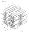
- the heat exchangers are arranged next to each other in a longitudinal direction BD of a corrugated fin 1 (corresponding to a width direction of the heat exchangers), so that their heat exchanger cores are arranged as partially shown in FIG. 4. Its arrangement is set similarly to that of the prior art described in the Japanese Applications Laid-open No. (Tokkaihei) 09 - 61081 for example.
- the heat exchanger cores have a plurality of radiator tubes 10 and radiator-core side fin portions 1b which are piled up at a radiator core side in a state where they are arranged alternatively, and a plurality of condenser tubes 11 and condenser-core side fin portions 1c which are piled up at a condenser core side in a state where they are arranged alternatively.
- the radiator-core side fin portions 1b and the condenser-core side fin portions 1c are arranged in a lateral direction AD (corresponding to a longitudinal direction of a motor vehicle body when the radiator and the condenser are mounted on it) and connected by connecting portions 1b. They are provided with a plurality of louvers 4 and 5 thereon, respectively.
- the first and second portions 1b and 1c and the connecting portions 1a are corrugated to have a plurality of top portions 2 and bottom portions 3 extending in the lateral direction AD so as to form a corrugated fin 1.
- the corrugated fin 1 is made of aluminum, and formed with a plurality of radiator louvers 4 on intermediate portions, formed between the top portions 2 and the bottom portions 3, of the radiator-core side fin portions 1b, and a plurality of condenser louvers 5 on intermediate portions, formed between the top portions 2 and the bottom portions 3, of the condenser-core side fin portions 1c.
- the radiator louvers 4 and the condenser louvers 5 are slanted in directions opposite to each other in the embodiment, but they may be slanted in the same direction.
- the connecting portions 1a are formed with slits 6 and 7 arranged in first and second lines and louvers 8 and 9 arranged in two lines.
- the slits 6 and 7 extend from a first intermediate portion to a third intermediate portion through one adjacent top portion 2, a second intermediate portion and one adjacent bottom portion 3 which are continuously formed in this order, and have a predetermined length W1.
- the slits 6 and 7 and their adjacent ones are apart from each other in the first and second lines by a predetermined space length W2 in the longitudinal direction BD, respectively.
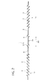
- the slits 6 and 7 and the louvers 8 and 9 are illustrated in detail in FIG. 3, in which its left part shows a side view of a part of the corrugated fin 1 and its right part shows a plan view of the same.
- the slits 6 and the slits facing each other in the lateral direction AD are located at the same positions in the longitudinal directions BD. Note that louvers 4 and 5 are omitted in FIG. 3 for facilitating visualization.
- the louvers 8 and 9 have a predetermined length W4, which is longer than the space length W2 and also than longitudinal lengths of the louvers 4 and 5.
- the louvers 8 and 9 and their adjacent louvers 8 and 9 are apart from each other in the longitudinal direction BD by a predetermined space length W3, respectively.
- the louvers 8 and 9 are formed between the slits 6 and 7 on each intermediate portion of the corrugated fin 1.
- the louvers 8 and 9 are slanted in directions opposite to each other in the embodiment so that the louvers 8 are slanted in the same direction as the radiator louvers 4 are and the louvers 9 are slanted in the same direction as the condenser louvers 5 are.
- they may have inclinations in the same direction.
- a space between the louvers 8 and 9 is set to have a predetermined length W5.
- a space between the slits 6 and the louvers 8 and a space between the louvers 9 and the slits 7 are set equally to have a predetermined space length W5' in the lateral direction AD, which is shorter a little than the length W5.
- top portions 2 and their adjacent bottom portions 3 are apart from each other in the longitudinal direction BD by a predetermined length W6.
- the slits 6 are preferable to be arranged in one line (the first line) and the slits 7 are also preferable to be arranged in one line (the second line), although they can be arranged respectively in plural lines. Setting more than one lines adjacent to each other for each of the slits 6 and 7 cannot often ensure sufficient stiffness of the corrugated fin 1 while forming the louvers 4, 5, 8 and 9 and/or corrugating fin material.
- louvers 8 and 9 may be set respectively in plural lines, whose number can be set arbitrarily, allowing for a length between the slits 6 and 7.
- An added length (W1 + W2) is set non-integral times as long as the length W6.
- the lengths W1 to W6 can be set arbitrarily.
- W6 is a longitudinal length corresponding to a development-elevation length of 7 mm, and a longitudinal length of the louvers 4 and 5 is 6.1 mm, which is shorter than the longitudinal length W4 of the louvers 8 and 9 on the connecting portions 1 a.
- corrugated fin is manufactured as follows.
- aluminum sheets in a strip-like shape are prepared as the fin material, and they are processed one by one.
- the aluminum sheet is notched by a not-shown cutter so as to form the slits 6 and 7 thereon.
- the slits 6 and 7 are obtained by shearing off the aluminum sheet and their widths may be arbitrary, extended or not extended.
- the slits 6 and 7 may be extended, for example as a draft holes, in this slit forming process or a fin brazing process, but their width extensions are not necessary. They may be formed by blanking of press.
- the aluminum sheet is corrugated by passing through a pair of corrugating rollers of a not-shown corrugating device to form a corrugated sheet.
- the louvers 4, 5, 8 and 9 are formed by cutting and raising them from the aluminum sheet to obtain the corrugated fin 1.
- the slits 6 are deformed to have an extended opening, with a predetermined width, directed outward (a left side of the corrugated fin 1 shown in FIG. 3) of the corrugated fin 1, due to stress caused during the process of the louvers 4 and 8 and stress caused during the process of corrugation.
- the slits 7 are deformed to have an extended opening, with predetermined width, directed outward (a right side of the corrugated fin 1 shown in FIG. 3), in a direction opposite to a direction of the slits 6, of the corrugated fin 1, due to the stress caused during the cutting and raising process for forming the louvers 4 and 8 and the stress caused during the process of corrugation.
- the above-constructed corrugated fins 1 are, as shown in FIG. 4, arranged alternatively with the radiator tubes 10 and the condenser tubes 11, respectively. They are piled up to form the radiator core and the condenser core in a state where one sheet of the corrugated fin 1 is used for the both cores of the integrally assembled heat exchangers as a common corrugated fin of them.
- slits 6 and 7 are formed to have the predetermined length W1, being respectively spaced by the predetermined length W2 from the adjacent slits 6 and 7, to traverse the top portion 2 and the bottom portion 3.
- the louvers 8 and 9 are provided on the intermediate portions formed between the top portion 2 and the bottom portion 3 and between the slits 6 and 7. The spaces between the slits 6 and 6 and the spaces between the slits 7 and 7 are isolated from each other in the lateral direction AD by the louvers 8 and 9.
- heat transfer passages X and Y from the radiator tubes 10 toward the condenser tubes 11 become sufficiently long by bypassing the louvers 8 and 9, thereby suppressing the heat transfer amount therebetween.
- the louvers 8 and 9 located between the slits 6 and 7 improve heat radiation and heat rejection performance in the connecting portion 1a of the corrugated fin 1.
- the slits 6 and 7 are deformed, during the corrugating, cutting and raising process, to extend their openings to have the predetermined length, being directed toward the outside of the corrugated fin 1 in the lateral direction AD. Therefore, they can improve the heat radiation and heat rejection performance in the connecting portion 1a of the corrugated fin 1 by easily passing the air through the openings, which can be formed without an additional process of extending the widths of the slits 6 and 7. Note that deformation of slits 6 and 7 to extend their openings is not necessarily needed for achieving the purpose of the present invention.
- the corrugated fin 1 for the integrally assembled heat exchangers of the embodiment has the following advantages.
- the corrugated fin 1 can improve the heat radiation performance in the connecting portion 1a of the corrugated fin 1 by forming the louvers 8 and 9 located between the slits 6 and 7, the louvers 8 and 9 and sufficiently long heat transfer passages X and Y bypassing the louvers 8 and 9.
- the added length (W1 + W2) is set non-integral times as long as the length W6, which can remove a synchronized process of a slit forming process and a louver forming process, accordingly enabling the corrugated fin 1 to be manufactured easily and at low cost.
- this brings the spaces having the length W2 and located between the slits 6 and 7 to be positioned erratically with respect to the corrugated fin 1. Therefore, this can prevent the spaces between the slits 6 and 7 from being always formed on the same positions, such as the top portions 2 or the bottom portions 3, due to time lag between the slit forming process and the louver forming process.
- the slits 6 and 7 facing each other in a lateral direction AD are located at the same positions in the longitudinal direction BD, which can provide the sufficiently long heat-transfer passages X and Y.
- the slits 6 and 7 are obtained by shearing off the aluminum sheet to for the draft holes, enabling them to be formed easily and at low cost.
- louvers 8 and 9 between the slits 6 and 7 are longer in the longitudinal length than the louvers 4 and 5 on the radiator-core side fin portions 1b and the condenser-core side fin portions 1c, which can improve insulation effectiveness in the connecting portions 1 a.
- another slit or other slits may be formed between the louvers 8 and 9, under a condition of avoiding an arrangement of adjacent slits in the latter case.
- the integrally assembled heat exchangers may employ other types of heat exchangers instead of a combination of the radiator and the condenser.
Landscapes
- Engineering & Computer Science (AREA)
- Physics & Mathematics (AREA)
- Thermal Sciences (AREA)
- Mechanical Engineering (AREA)
- General Engineering & Computer Science (AREA)
- Geometry (AREA)
- Heat-Exchange Devices With Radiators And Conduit Assemblies (AREA)
- Air-Conditioning For Vehicles (AREA)
Abstract
Description
- The present invention relates to a corrugated fin for integrally assembled heat exchangers which are integrally arranged next to each other, each having a plurality of tubes and corrugated fins which are arranged alternatively.
- A corrugated fin for integrally assembled heat exchangers is described in
Japanese Patent Applications Laid-open No. (Tokkaihei) 09 - 61081 tokkaihei) 11 - 142079 - However, the above-described conventional corrugated fin has problems in sufficiently decreasing a heat transfer amount between the heat exchangers through the connecting portion because the connecting portion is too short to radiate heat therefrom sufficiently, although the slits can decrease the heat transfer amount between the heat exchangers to some extent.
- It is, therefore, an object of the present invention to provide a corrugated fin for integrally assembled heat exchangers that overcomes the foregoing drawbacks and can improve heat radiation performance in a connecting portion that connects fin portions of a corrugated fin respectively used for the heat exchangers, suppressing heat transfer between the adjacent heat exchangers.
- According to a first aspect of the present invention there is provided a corrugated fin for integrated assembled heat exchangers, the heat exchangers having a plurality of tubes and corrugated fins which are piled up in a state where the tubes and the corrugated fins are arranged alternatively, and the corrugated fin having top portions and bottom portions, the corrugated fin comprising: fin portions used for the integrally assembled heat exchangers, respectively; a connecting portion located between the integrally assembled heat exchangers and connecting the fin portions with each other, the connecting portion being formed with slits arranged in a first line and a second line which extend in a longitudinal direction of the corrugated fin so that a space is formed between the adjacent slits in the first line and between the adjacent slits in the second line, respectively, and the connecting portion being provided with at least one louver between the slits in the first and second lines, characterized in that the slits in the first line and the slits in the second line traverse the top portion and the bottom portion adjacent to the top portion of the corrugated fin and the louver is formed on an intermediate portion formed between the top portion and the bottom portion so that the louver is located between the space of the slits in the first line and the space of the slits in the second line.
- The objects, features and advantages of the present invention will become apparent as the description proceeds when taken in conjunction with the accompanying drawings, in which:
- FIG. 1 is a perspective view showing a corrugated fin used for integrally assembled heat exchangers of an embodiment according to the present invention;
- FIG. 2 is a sectional view of the corrugated fin taken along the lines S2 - S2 of FIG. 1;
- FIG. 3 is an illustration explaining slits and louvers formed on a connecting portion of the corrugated fin of the embodiment, omitting louvers formed on fin portions of the corrugated fin shown in FIGS. 1 and 2; and
- FIG. 4 is a perspective view showing two cores of the integrally assembled heat exchangers to which the corrugated fins of the embodiment shown in FIGS. 1 to 3 are applied.
- Throughout the following detailed description, similar reference characters and numbers refer to similar elements in all figures of the drawings, and their descriptions are omitted for eliminating duplication.
- A corrugated fin for integrally assembled heat exchangers of an embodiment according to the present invention will be described with reference to the accompanying drawings.
- The integrally assembled heat exchangers are for different uses, functioning as ,for example, a radiator and a condenser of a motor vehicle. The heat exchangers are arranged next to each other in a longitudinal direction BD of a corrugated fin 1 (corresponding to a width direction of the heat exchangers), so that their heat exchanger cores are arranged as partially shown in FIG. 4. Its arrangement is set similarly to that of the prior art described in the
Japanese Applications Laid-open No. (Tokkaihei) 09 - 61081 - The heat exchanger cores have a plurality of
radiator tubes 10 and radiator-coreside fin portions 1b which are piled up at a radiator core side in a state where they are arranged alternatively, and a plurality ofcondenser tubes 11 and condenser-core sidefin portions 1c which are piled up at a condenser core side in a state where they are arranged alternatively. - The radiator-core side
fin portions 1b and the condenser-core sidefin portions 1c are arranged in a lateral direction AD (corresponding to a longitudinal direction of a motor vehicle body when the radiator and the condenser are mounted on it) and connected by connectingportions 1b. They are provided with a plurality oflouvers - The first and
second portions portions 1a are corrugated to have a plurality oftop portions 2 andbottom portions 3 extending in the lateral direction AD so as to form acorrugated fin 1. - The
corrugated fin 1 is made of aluminum, and formed with a plurality ofradiator louvers 4 on intermediate portions, formed between thetop portions 2 and thebottom portions 3, of the radiator-core sidefin portions 1b, and a plurality ofcondenser louvers 5 on intermediate portions, formed between thetop portions 2 and thebottom portions 3, of the condenser-core sidefin portions 1c. Theradiator louvers 4 and thecondenser louvers 5 are slanted in directions opposite to each other in the embodiment, but they may be slanted in the same direction. - The connecting
portions 1a are formed withslits louvers - The
slits adjacent top portion 2, a second intermediate portion and oneadjacent bottom portion 3 which are continuously formed in this order, and have a predetermined length W1. Theslits slits louvers corrugated fin 1 and its right part shows a plan view of the same. Theslits 6 and the slits facing each other in the lateral direction AD are located at the same positions in the longitudinal directions BD. Note thatlouvers - The
louvers louvers louvers adjacent louvers louvers slits corrugated fin 1. Thelouvers louvers 8 are slanted in the same direction as theradiator louvers 4 are and thelouvers 9 are slanted in the same direction as thecondenser louvers 5 are. Instead of the above-describedlouvers - A space between the
louvers slits 6 and thelouvers 8 and a space between thelouvers 9 and theslits 7 are set equally to have a predetermined space length W5' in the lateral direction AD, which is shorter a little than the length W5. - Incidentally, the
top portions 2 and theiradjacent bottom portions 3 are apart from each other in the longitudinal direction BD by a predetermined length W6. - In this embodiment, the
slits 6 are preferable to be arranged in one line (the first line) and theslits 7 are also preferable to be arranged in one line (the second line), although they can be arranged respectively in plural lines. Setting more than one lines adjacent to each other for each of theslits corrugated fin 1 while forming thelouvers - On the other hand, the
louvers slits - An added length (W1 + W2) is set non-integral times as long as the length W6. The lengths W1 to W6 can be set arbitrarily. In this embodiment, the lengths W1 to W5 are set as follows: W1 = 12.5 mm, W2 = 1.5 mm, W3 = 0.5 mm, W4 = 6.5 mm, W5' = 1.3 mm and W5 = 2 mm. W6 is a longitudinal length corresponding to a development-elevation length of 7 mm, and a longitudinal length of the
louvers louvers portions 1 a. - The above-described corrugated fin is manufactured as follows.
- First, aluminum sheets in a strip-like shape are prepared as the fin material, and they are processed one by one.
- The aluminum sheet is notched by a not-shown cutter so as to form the
slits slits slits - Then, the aluminum sheet is corrugated by passing through a pair of corrugating rollers of a not-shown corrugating device to form a corrugated sheet. At the same time, the
louvers corrugated fin 1. - During this corrugating, cutting and raising process, the
slits 6 are deformed to have an extended opening, with a predetermined width, directed outward (a left side of thecorrugated fin 1 shown in FIG. 3) of thecorrugated fin 1, due to stress caused during the process of thelouvers - Similarly, the
slits 7 are deformed to have an extended opening, with predetermined width, directed outward (a right side of thecorrugated fin 1 shown in FIG. 3), in a direction opposite to a direction of theslits 6, of thecorrugated fin 1, due to the stress caused during the cutting and raising process for forming thelouvers - The above-constructed
corrugated fins 1 are, as shown in FIG. 4, arranged alternatively with theradiator tubes 10 and thecondenser tubes 11, respectively. They are piled up to form the radiator core and the condenser core in a state where one sheet of thecorrugated fin 1 is used for the both cores of the integrally assembled heat exchangers as a common corrugated fin of them. - These integrally assembled heat exchangers are mounted on the vehicle body with a not-shown fan driven by an electric motor.
- The operation of the corrugated fin for the integrally assembled heat exchangers of the embodiment will be described.
- Coolant flowing in the
radiator tubes 10, usually having a temperature between approximately 110°C and approximately 60°C, is cooled by exchanging heat between the coolant and the air, generated by the fan and/or movement of the motor vehicle, flowing through the radiator-core sidefin portions 1b with thelouvers 4. - Cooling medium flowing in the
condenser tubes 11, usually having a temperature between approximately 80°C and approximately 40°C, is cooled by exchanging heat between the cooling medium and the air, generated by the fan and/or movement of the motor vehicle, flowing through the condenser-core sidefin portions 1c with thelouvers 5. - As described above, heat transfers from the
radiator tubes 10 toward thecondenser tubes 11 the connectingportions 1a due to temperature difference between the coolant and the cooling medium, thereby heating up the cooling medium to decrease coolability of the condenser. Note that the heat transfers from the condenser toward the radiator through the connectingportions 1 a under some use conditions of the radiator and according to a use purpose of the radiator. - As shown in FIG. 3, in the
corrugated fin 1 of the embodiment,slits adjacent slits top portion 2 and thebottom portion 3. In addition to that, as shown in FIGS. 1, 2 and 4, thelouvers top portion 2 and thebottom portion 3 and between theslits slits slits louvers - Therefore, as shown in FIG. 3, heat transfer passages X and Y from the
radiator tubes 10 toward thecondenser tubes 11 become sufficiently long by bypassing thelouvers louvers slits portion 1a of thecorrugated fin 1. - Further, the
slits corrugated fin 1 in the lateral direction AD. Therefore, they can improve the heat radiation and heat rejection performance in the connectingportion 1a of thecorrugated fin 1 by easily passing the air through the openings, which can be formed without an additional process of extending the widths of theslits slits - The
corrugated fin 1 for the integrally assembled heat exchangers of the embodiment has the following advantages. - The
corrugated fin 1 can improve the heat radiation performance in the connectingportion 1a of thecorrugated fin 1 by forming thelouvers slits louvers louvers - The added length (W1 + W2) is set non-integral times as long as the length W6, which can remove a synchronized process of a slit forming process and a louver forming process, accordingly enabling the
corrugated fin 1 to be manufactured easily and at low cost. - In addition, this brings the spaces having the length W2 and located between the
slits corrugated fin 1. Therefore, this can prevent the spaces between theslits top portions 2 or thebottom portions 3, due to time lag between the slit forming process and the louver forming process. - The
slits - The
slits - The
louvers slits louvers side fin portions 1b and the condenser-coreside fin portions 1c, which can improve insulation effectiveness in the connectingportions 1 a. - While there have been particularly shown and described with reference to preferred embodiments thereof, it will be understood that various modifications may be made therein.
- For example, another slit or other slits may be formed between the
louvers - The integrally assembled heat exchangers may employ other types of heat exchangers instead of a combination of the radiator and the condenser.
Claims (7)
- A corrugated fin (1) for integrally assembled heat exchangers, the heat exchangers having a plurality of tubes (10, 11) and corrugated fins (1) which are piled up in a state where the tubes (10; 11) and the corrugated fins (1) are arranged alternatively, and the corrugated fin (1) having top portions (2) and bottom portions (3), the corrugated fin (1) comprising:fin portions (1b, 1c) used for the integrally assembled heat exchangers, respectively;a connecting portion (1a) located between the integrally assembled heat exchangers and connecting the fin portions (1b, 1c) with each other, the connecting portion (1a) being formed with slits (6, 7) arranged in a first line and a second line which extend in a longitudinal direction (BD) of the corrugated fin (1) so that a space is formed between the adjacent slits (6; 7) in the first line and between the adjacent slits (7; 6) in the second line, respectively, and the connecting portion (1a) being provided with at least one louver (8, 9) between the slits (6, 7) in the first and second lines, characterized in thatthe slits (6; 7) in the first line and the slits (7; 6) in the second line traverse the top portion (2) and the bottom portion (3) adjacent to the top portion (2) of the corrugated fin (1) and the louver (8, 9) is formed on an intermediate portion formed between the top portion (2) and the bottom portion (3) so that the louver (8, 9) is located between the space of the slits (6; 7) in the first line and the space of the slits (7; 6) in the second line.
- The Corrugated fin (1) according to claim 1, characterized in that
an added length (W 1 + W2) is set non-integral times as long as a length W6, where W1 is a longitudinal length of the slit (6, 7), W2 is a length of the space between the adjacent slits (6, 7), and W6 is a longitudinal length between the top portion (2) and the bottom portion (3) adjacent to the top portion (2) of the corrugated fin (1). - The Corrugated fin (1) according to claim 2, characterized in that
the slits (6, 7) facing each other in a lateral direction (AD) of the corrugated fin (1) are located at the same positions in the longitudinal direction (BD). - The Corrugated fin (1) according to any one of claims 1 to 3, characterized in that
the slits (6, 7) are formed by shearing-off fin material. - The Corrugated fin (1) according to claim 4, characterized in that
the slits (6, 7) are formed to have a draft hole. - The Corrugated fin (1) according to any one of claims 1 to 5, characterized in that
the louvers (8, 9) located between the slits (6, 7) are longer in a longitudinal length (BD) than louvers (4, 5) provided on the fin portions (1b, 1c). - The Corrugated fin (1) according to any one of claims 1 to 6, characterized in that
the slits (6, 7) are formed to be directed outward of the corrugated fin (1) in a lateral direction (AD) of the corrugated fin (1).
Applications Claiming Priority (1)
| Application Number | Priority Date | Filing Date | Title |
|---|---|---|---|
| JP2005117543A JP4683987B2 (en) | 2005-04-14 | 2005-04-14 | Fin structure of integrated heat exchanger |
Publications (2)
| Publication Number | Publication Date |
|---|---|
| EP1712865A1 true EP1712865A1 (en) | 2006-10-18 |
| EP1712865B1 EP1712865B1 (en) | 2008-03-12 |
Family
ID=36678519
Family Applications (1)
| Application Number | Title | Priority Date | Filing Date |
|---|---|---|---|
| EP06112641A Expired - Lifetime EP1712865B1 (en) | 2005-04-14 | 2006-04-13 | Corrugate fin for integrally assembled heat exchangers |
Country Status (4)
| Country | Link |
|---|---|
| US (1) | US7478669B2 (en) |
| EP (1) | EP1712865B1 (en) |
| JP (1) | JP4683987B2 (en) |
| DE (1) | DE602006000675T2 (en) |
Families Citing this family (7)
| Publication number | Priority date | Publication date | Assignee | Title |
|---|---|---|---|---|
| GB2519407A (en) * | 2013-08-14 | 2015-04-22 | Hamilton Sundstrand Corp | Bendable heat exchanger |
| US10112270B2 (en) * | 2013-08-21 | 2018-10-30 | Hamilton Sundstrand Corporation | Heat exchanger fin with crack arrestor |
| JP6687967B2 (en) | 2014-03-24 | 2020-04-28 | 株式会社デンソー | Heat exchanger |
| CN105066518B (en) * | 2015-08-04 | 2018-01-05 | 广东美的制冷设备有限公司 | A kind of double rows parallel flow evaporator and its air-conditioning device with the evaporator |
| US11009300B2 (en) | 2017-02-21 | 2021-05-18 | Mitsubishi Electric Corporation | Heat exchanger and air-conditioning apparatus |
| CN111417293A (en) * | 2020-05-11 | 2020-07-14 | 无锡金鑫集团股份有限公司 | Heat sink |
| US12624904B2 (en) | 2021-04-13 | 2026-05-12 | Mitsubishi Electric Corporation | Heat exchanger and refrigeration cycle apparatus |
Citations (6)
| Publication number | Priority date | Publication date | Assignee | Title |
|---|---|---|---|---|
| EP0431917A1 (en) * | 1989-12-07 | 1991-06-12 | Showa Aluminum Kabushiki Kaisha | Consolidated duplex heat exchanger |
| JPH0961081A (en) * | 1995-08-24 | 1997-03-07 | Calsonic Corp | Fins for integrated heat exchanger |
| EP1030153A1 (en) * | 1997-11-13 | 2000-08-23 | Zexel Corporation | Fin for a one-piece heat exchanger and method of manufacturing the fin |
| EP1164345A1 (en) * | 1999-12-14 | 2001-12-19 | Denso Corporation | Heat exchanger |
| EP1241424A2 (en) * | 2001-03-16 | 2002-09-18 | Calsonic Kansei Corporation | Core structure of integral heat-exchanger |
| FR2849174A1 (en) * | 2002-12-23 | 2004-06-25 | Valeo Thermique Moteur Sa | Heat exchanger cooling fin is constituted from strip comprising first and second heat exchange zones cooperating respectively with first and second heat exchanger tubes and weakening zone able allowing separation into these zones |
Family Cites Families (6)
| Publication number | Priority date | Publication date | Assignee | Title |
|---|---|---|---|---|
| JPH0214582U (en) * | 1988-07-08 | 1990-01-30 | ||
| JPH0645155Y2 (en) * | 1988-10-24 | 1994-11-16 | サンデン株式会社 | Heat exchanger |
| US5289874A (en) * | 1993-06-28 | 1994-03-01 | General Motors Corporation | Heat exchanger with laterally displaced louvered fin sections |
| ES2127472T3 (en) * | 1994-04-12 | 1999-04-16 | Showa Aluminum Corp | STACKED DUPLEX HEAT EXCHANGER. |
| US6095239A (en) * | 1996-08-12 | 2000-08-01 | Calsonic Kansei Corporation | Integral-type heat exchanger |
| JP4379967B2 (en) * | 1999-03-30 | 2009-12-09 | 株式会社デンソー | Double heat exchanger |
-
2005
- 2005-04-14 JP JP2005117543A patent/JP4683987B2/en not_active Expired - Fee Related
-
2006
- 2006-04-13 EP EP06112641A patent/EP1712865B1/en not_active Expired - Lifetime
- 2006-04-13 DE DE602006000675T patent/DE602006000675T2/en not_active Expired - Fee Related
- 2006-04-13 US US11/403,207 patent/US7478669B2/en not_active Expired - Fee Related
Patent Citations (6)
| Publication number | Priority date | Publication date | Assignee | Title |
|---|---|---|---|---|
| EP0431917A1 (en) * | 1989-12-07 | 1991-06-12 | Showa Aluminum Kabushiki Kaisha | Consolidated duplex heat exchanger |
| JPH0961081A (en) * | 1995-08-24 | 1997-03-07 | Calsonic Corp | Fins for integrated heat exchanger |
| EP1030153A1 (en) * | 1997-11-13 | 2000-08-23 | Zexel Corporation | Fin for a one-piece heat exchanger and method of manufacturing the fin |
| EP1164345A1 (en) * | 1999-12-14 | 2001-12-19 | Denso Corporation | Heat exchanger |
| EP1241424A2 (en) * | 2001-03-16 | 2002-09-18 | Calsonic Kansei Corporation | Core structure of integral heat-exchanger |
| FR2849174A1 (en) * | 2002-12-23 | 2004-06-25 | Valeo Thermique Moteur Sa | Heat exchanger cooling fin is constituted from strip comprising first and second heat exchange zones cooperating respectively with first and second heat exchanger tubes and weakening zone able allowing separation into these zones |
Non-Patent Citations (1)
| Title |
|---|
| PATENT ABSTRACTS OF JAPAN vol. 1997, no. 07 31 July 1997 (1997-07-31) * |
Also Published As
| Publication number | Publication date |
|---|---|
| US7478669B2 (en) | 2009-01-20 |
| US20060237173A1 (en) | 2006-10-26 |
| JP4683987B2 (en) | 2011-05-18 |
| EP1712865B1 (en) | 2008-03-12 |
| DE602006000675T2 (en) | 2009-04-23 |
| DE602006000675D1 (en) | 2008-04-24 |
| JP2006292336A (en) | 2006-10-26 |
Similar Documents
| Publication | Publication Date | Title |
|---|---|---|
| US6502305B2 (en) | Method of manufacturing a heat-exchanger fin, fins according to the method and exchange module including these fins | |
| JP4482991B2 (en) | Double heat exchanger | |
| EP0367078B1 (en) | Heat exchanger | |
| EP0431917B1 (en) | Consolidated duplex heat exchanger | |
| JP5397543B2 (en) | Heat exchanger and manufacturing method thereof | |
| US6968891B2 (en) | Louver fin and corrugation cutter for forming louver fin | |
| US6889757B2 (en) | Core structure of integral heat-exchanger | |
| MX2011004502A (en) | Fin for a heat exchanger, and heat exchanger including such a fin. | |
| EP2778592B1 (en) | Heat exchanger assembly having split mini-louvered fins | |
| KR20110083017A (en) | Fins for heat exchanger and heat exchanger with same | |
| JP2000346578A (en) | Double heat exchanger | |
| JP2001099593A (en) | Double heat exchanger | |
| JP2002228379A (en) | Louver fin of heat exchanger, its heat exchanger, and method of assembling the louver fin | |
| JP2006207948A (en) | Air-cooled oil cooler | |
| US6871399B2 (en) | Method for producing an integrated heat exchanger and an integrated heat exchanger produced thereby | |
| EP1712865B1 (en) | Corrugate fin for integrally assembled heat exchangers | |
| JP4459062B2 (en) | HEAT EXCHANGE MODULE AND METHOD FOR PRODUCING HEAT EXCHANGE MODULE | |
| JP4173959B2 (en) | Integrated heat exchanger core structure | |
| JP5569410B2 (en) | Heat exchanger tubes and heat exchangers | |
| JP2005090760A (en) | Heat exchanger | |
| JP4358961B2 (en) | Evaporator fin | |
| JP2005003350A (en) | Heat exchanger fin, heat exchanger, condenser and evaporator | |
| JP2017101842A (en) | Heat exchanger | |
| EP1193460A2 (en) | Core structure of integral heat-exchanger | |
| EP3372940A1 (en) | A heat exchanger and a method to produce an offset strip fin for the heat exchanger |
Legal Events
| Date | Code | Title | Description |
|---|---|---|---|
| PUAI | Public reference made under article 153(3) epc to a published international application that has entered the european phase |
Free format text: ORIGINAL CODE: 0009012 |
|
| AK | Designated contracting states |
Kind code of ref document: A1 Designated state(s): AT BE BG CH CY CZ DE DK EE ES FI FR GB GR HU IE IS IT LI LT LU LV MC NL PL PT RO SE SI SK TR |
|
| AX | Request for extension of the european patent |
Extension state: AL BA HR MK YU |
|
| 17P | Request for examination filed |
Effective date: 20061027 |
|
| GRAP | Despatch of communication of intention to grant a patent |
Free format text: ORIGINAL CODE: EPIDOSNIGR1 |
|
| AKX | Designation fees paid |
Designated state(s): DE FR GB |
|
| GRAS | Grant fee paid |
Free format text: ORIGINAL CODE: EPIDOSNIGR3 |
|
| GRAA | (expected) grant |
Free format text: ORIGINAL CODE: 0009210 |
|
| AK | Designated contracting states |
Kind code of ref document: B1 Designated state(s): DE FR GB |
|
| REG | Reference to a national code |
Ref country code: GB Ref legal event code: FG4D |
|
| REF | Corresponds to: |
Ref document number: 602006000675 Country of ref document: DE Date of ref document: 20080424 Kind code of ref document: P |
|
| ET | Fr: translation filed | ||
| PLBE | No opposition filed within time limit |
Free format text: ORIGINAL CODE: 0009261 |
|
| STAA | Information on the status of an ep patent application or granted ep patent |
Free format text: STATUS: NO OPPOSITION FILED WITHIN TIME LIMIT |
|
| 26N | No opposition filed |
Effective date: 20081215 |
|
| PGFP | Annual fee paid to national office [announced via postgrant information from national office to epo] |
Ref country code: DE Payment date: 20090409 Year of fee payment: 4 Ref country code: FR Payment date: 20090417 Year of fee payment: 4 |
|
| GBPC | Gb: european patent ceased through non-payment of renewal fee |
Effective date: 20100413 |
|
| REG | Reference to a national code |
Ref country code: FR Ref legal event code: ST Effective date: 20101230 |
|
| PG25 | Lapsed in a contracting state [announced via postgrant information from national office to epo] |
Ref country code: DE Free format text: LAPSE BECAUSE OF NON-PAYMENT OF DUE FEES Effective date: 20101103 |
|
| PG25 | Lapsed in a contracting state [announced via postgrant information from national office to epo] |
Ref country code: GB Free format text: LAPSE BECAUSE OF NON-PAYMENT OF DUE FEES Effective date: 20100413 |
|
| PG25 | Lapsed in a contracting state [announced via postgrant information from national office to epo] |
Ref country code: FR Free format text: LAPSE BECAUSE OF NON-PAYMENT OF DUE FEES Effective date: 20100430 |