EP1712341A2 - Injection nozzle with two outlet orifices - Google Patents
Injection nozzle with two outlet orifices Download PDFInfo
- Publication number
- EP1712341A2 EP1712341A2 EP06006648A EP06006648A EP1712341A2 EP 1712341 A2 EP1712341 A2 EP 1712341A2 EP 06006648 A EP06006648 A EP 06006648A EP 06006648 A EP06006648 A EP 06006648A EP 1712341 A2 EP1712341 A2 EP 1712341A2
- Authority
- EP
- European Patent Office
- Prior art keywords
- closure
- injection molding
- molding nozzle
- nozzle according
- outlet openings
- Prior art date
- Legal status (The legal status is an assumption and is not a legal conclusion. Google has not performed a legal analysis and makes no representation as to the accuracy of the status listed.)
- Granted
Links
- 238000002347 injection Methods 0.000 title claims abstract description 28
- 239000007924 injection Substances 0.000 title claims abstract description 28
- 238000001746 injection moulding Methods 0.000 claims abstract description 21
- 230000009286 beneficial effect Effects 0.000 description 1
- 230000001419 dependent effect Effects 0.000 description 1
- 238000011161 development Methods 0.000 description 1
- 230000018109 developmental process Effects 0.000 description 1
- 238000004519 manufacturing process Methods 0.000 description 1
- 239000000155 melt Substances 0.000 description 1
- 238000000034 method Methods 0.000 description 1
- 239000013641 positive control Substances 0.000 description 1
- 238000010992 reflux Methods 0.000 description 1
- 239000000243 solution Substances 0.000 description 1
Images


Classifications
-
- B—PERFORMING OPERATIONS; TRANSPORTING
- B29—WORKING OF PLASTICS; WORKING OF SUBSTANCES IN A PLASTIC STATE IN GENERAL
- B29C—SHAPING OR JOINING OF PLASTICS; SHAPING OF MATERIAL IN A PLASTIC STATE, NOT OTHERWISE PROVIDED FOR; AFTER-TREATMENT OF THE SHAPED PRODUCTS, e.g. REPAIRING
- B29C45/00—Injection moulding, i.e. forcing the required volume of moulding material through a nozzle into a closed mould; Apparatus therefor
- B29C45/17—Component parts, details or accessories; Auxiliary operations
- B29C45/26—Moulds
- B29C45/27—Sprue channels ; Runner channels or runner nozzles
- B29C45/28—Closure devices therefor
- B29C45/2806—Closure devices therefor consisting of needle valve systems
- B29C45/281—Drive means therefor
-
- B—PERFORMING OPERATIONS; TRANSPORTING
- B29—WORKING OF PLASTICS; WORKING OF SUBSTANCES IN A PLASTIC STATE IN GENERAL
- B29C—SHAPING OR JOINING OF PLASTICS; SHAPING OF MATERIAL IN A PLASTIC STATE, NOT OTHERWISE PROVIDED FOR; AFTER-TREATMENT OF THE SHAPED PRODUCTS, e.g. REPAIRING
- B29C45/00—Injection moulding, i.e. forcing the required volume of moulding material through a nozzle into a closed mould; Apparatus therefor
- B29C45/17—Component parts, details or accessories; Auxiliary operations
- B29C45/26—Moulds
- B29C45/27—Sprue channels ; Runner channels or runner nozzles
- B29C45/2735—Sprue channels ; Runner channels or runner nozzles for non-coaxial gates, e.g. for edge gates
-
- B—PERFORMING OPERATIONS; TRANSPORTING
- B29—WORKING OF PLASTICS; WORKING OF SUBSTANCES IN A PLASTIC STATE IN GENERAL
- B29C—SHAPING OR JOINING OF PLASTICS; SHAPING OF MATERIAL IN A PLASTIC STATE, NOT OTHERWISE PROVIDED FOR; AFTER-TREATMENT OF THE SHAPED PRODUCTS, e.g. REPAIRING
- B29C45/00—Injection moulding, i.e. forcing the required volume of moulding material through a nozzle into a closed mould; Apparatus therefor
- B29C45/17—Component parts, details or accessories; Auxiliary operations
- B29C45/26—Moulds
- B29C45/27—Sprue channels ; Runner channels or runner nozzles
- B29C2045/2779—Nozzles with a plurality of outlets
-
- B—PERFORMING OPERATIONS; TRANSPORTING
- B29—WORKING OF PLASTICS; WORKING OF SUBSTANCES IN A PLASTIC STATE IN GENERAL
- B29C—SHAPING OR JOINING OF PLASTICS; SHAPING OF MATERIAL IN A PLASTIC STATE, NOT OTHERWISE PROVIDED FOR; AFTER-TREATMENT OF THE SHAPED PRODUCTS, e.g. REPAIRING
- B29C45/00—Injection moulding, i.e. forcing the required volume of moulding material through a nozzle into a closed mould; Apparatus therefor
- B29C45/17—Component parts, details or accessories; Auxiliary operations
- B29C45/26—Moulds
- B29C45/27—Sprue channels ; Runner channels or runner nozzles
- B29C45/28—Closure devices therefor
- B29C45/2806—Closure devices therefor consisting of needle valve systems
- B29C45/281—Drive means therefor
- B29C2045/2813—Common drive means for several needle valves
-
- B—PERFORMING OPERATIONS; TRANSPORTING
- B29—WORKING OF PLASTICS; WORKING OF SUBSTANCES IN A PLASTIC STATE IN GENERAL
- B29C—SHAPING OR JOINING OF PLASTICS; SHAPING OF MATERIAL IN A PLASTIC STATE, NOT OTHERWISE PROVIDED FOR; AFTER-TREATMENT OF THE SHAPED PRODUCTS, e.g. REPAIRING
- B29C45/00—Injection moulding, i.e. forcing the required volume of moulding material through a nozzle into a closed mould; Apparatus therefor
- B29C45/17—Component parts, details or accessories; Auxiliary operations
- B29C45/26—Moulds
- B29C45/27—Sprue channels ; Runner channels or runner nozzles
- B29C45/28—Closure devices therefor
- B29C45/2806—Closure devices therefor consisting of needle valve systems
- B29C45/281—Drive means therefor
- B29C2045/2831—Needle valves driven by a cam
-
- B—PERFORMING OPERATIONS; TRANSPORTING
- B29—WORKING OF PLASTICS; WORKING OF SUBSTANCES IN A PLASTIC STATE IN GENERAL
- B29C—SHAPING OR JOINING OF PLASTICS; SHAPING OF MATERIAL IN A PLASTIC STATE, NOT OTHERWISE PROVIDED FOR; AFTER-TREATMENT OF THE SHAPED PRODUCTS, e.g. REPAIRING
- B29C45/00—Injection moulding, i.e. forcing the required volume of moulding material through a nozzle into a closed mould; Apparatus therefor
- B29C45/17—Component parts, details or accessories; Auxiliary operations
- B29C45/26—Moulds
- B29C45/27—Sprue channels ; Runner channels or runner nozzles
- B29C45/28—Closure devices therefor
- B29C45/2806—Closure devices therefor consisting of needle valve systems
- B29C45/281—Drive means therefor
- B29C2045/2841—Needle valves driven by a plurality of coaxial pistons
-
- B—PERFORMING OPERATIONS; TRANSPORTING
- B29—WORKING OF PLASTICS; WORKING OF SUBSTANCES IN A PLASTIC STATE IN GENERAL
- B29C—SHAPING OR JOINING OF PLASTICS; SHAPING OF MATERIAL IN A PLASTIC STATE, NOT OTHERWISE PROVIDED FOR; AFTER-TREATMENT OF THE SHAPED PRODUCTS, e.g. REPAIRING
- B29C45/00—Injection moulding, i.e. forcing the required volume of moulding material through a nozzle into a closed mould; Apparatus therefor
- B29C45/17—Component parts, details or accessories; Auxiliary operations
- B29C45/26—Moulds
- B29C45/27—Sprue channels ; Runner channels or runner nozzles
- B29C45/28—Closure devices therefor
- B29C45/2806—Closure devices therefor consisting of needle valve systems
- B29C2045/2872—Closure devices therefor consisting of needle valve systems with at least three positions, e.g. two different open positions to control the melt flow
-
- B—PERFORMING OPERATIONS; TRANSPORTING
- B29—WORKING OF PLASTICS; WORKING OF SUBSTANCES IN A PLASTIC STATE IN GENERAL
- B29C—SHAPING OR JOINING OF PLASTICS; SHAPING OF MATERIAL IN A PLASTIC STATE, NOT OTHERWISE PROVIDED FOR; AFTER-TREATMENT OF THE SHAPED PRODUCTS, e.g. REPAIRING
- B29C45/00—Injection moulding, i.e. forcing the required volume of moulding material through a nozzle into a closed mould; Apparatus therefor
- B29C45/17—Component parts, details or accessories; Auxiliary operations
- B29C45/40—Removing or ejecting moulded articles
- B29C45/44—Removing or ejecting moulded articles for undercut articles
Definitions
- the invention relates to an injection molding nozzle according to the preamble of claim 1, with at least one outlet opening, and at least one positively controlled closure element, by means of which a connection opening of an injection mold can be closed.
- Such injection molding is for example from the DE 38 43 035 A1 known.
- the known injection molding nozzle has at the end of a feed channel for plastic melt an outlet opening through which a valve pin extends.
- By means of the closure needle it is possible to close a connection opening of an injection mold connected to the outlet opening of the injection molding nozzle.
- the supply of plastic melt through the outlet opening into the injection mold is prevented and, on the other hand, a reflux of plastic melt from the injection mold is prevented.
- This known injection molding nozzle has two outlet openings facing in opposite directions, through each of which a closure needle extends, by means of which in each case a connection opening of an injection mold can be closed.
- Each outlet opening is connected to a supply channel for plastic, so that exit plastic from the outlet openings and the connection opening of the injection mold can be supplied.
- the closure needles of the known injection molding nozzles are moved axially so far that they extend into the respective attachment openings of the respective injection molds, whereby they are sealed.
- the closure needles In order to obtain a perfect surface of the injection-molded parts to be produced, it is necessary for the closure needles to penetrate into the connection openings so far that the end face of the closure needles is flush with the surface of the injection-molded part concerned. This is in practice, however extremely difficult to reach. There are therefore complicated adjustments required.
- valve needle Does not protrude the valve needle far enough into the connection opening, that is, is the end face of the valve needle at a distance from the surface of the injection molded part, forms at the gate a small stopper. If the valve needle protrudes into the connection opening so far that it extends into the injection-molded part, streaks can form on the surface of the injection-molded part when the injection-molded part is removed from the mold, as a result of which it may no longer be necessary.
- an injection molding nozzle with at least one outlet opening and at least one positively controlled closure element by means of which a connection opening of an injection mold is closable, characterized in that short-stroke means are present, by means of which the closure element is adjustable by a short stroke against the closing direction of the closure element.
- a short stroke of about 0.05 to 1 millimeter, in particular 0.1 to 0.5 millimeter, preferably 0.3 millimeter, has proven to be very advantageous.
- the closure element can be actuated by means of a drive, which has a restoring element with a working position and a rest position, which automatically assumes its rest position when the drive is not actuated.
- a drive which has a return element, the short stroke against the closing direction of the closure element is realized in a simple manner.
- the restoring element reaches its working position, in which the closure element projects into the injection-molded part.
- the return element passes from its working position to its rest position, whereby the closure element travels a short distance against the closing direction, so that the closure element no longer projects into the injection molded part but is arranged at a distance from the injection molded part. Due to the reset element, the short stroke can be very easily and very accurately.
- the return element is designed as a plate spring, as provided in a further particular embodiment of the invention, it is very advantageous is.
- Such formed resetting element can be produced in a simple manner and thus cost and works very accurate and reliable.
- the return element can also be designed as a separate pneumatically or hydraulically operated element or another known from the injection molding technique shutter needle drive system, such as a Kurzhubzylinder. This makes it possible to generate a large force with a small design.
- At least two outlet openings pointing in different directions are present, the closure elements of which are adjustable by means of an adjusting means.
- the drive for the closure elements can thus act on a common adjusting means.
- the short stroke can be carried out simultaneously against the closing direction in the case of all closure elements.
- closure elements are adjustable by means of an adjusting means advantageously achieves that the movements of the closure elements take place synchronously and uniformly. That is, the opening or closing of the connection openings has substantially the same course in all connection openings. As a result, a very uniform filling of the injection mold is achieved. This in turn has a very beneficial effect on the quality of the injection molded parts.
- closure elements are controlled by means of a slotted guide. This makes it possible to achieve a very precise adjustment of the closure elements.
- closure elements are formed as a closure needles which extend through the outlet openings and at their outlet openings opposite ends are T-shaped and each extending in a longitudinally of a cone or a wedge T -Nut of a central rod arranged are.
- closure elements can penetrate relatively far into the connection openings of an injection mold, it is possible to form the closure needles in a cylindrical shape at their ends which extend through the outlet openings. As a result, the production of the closure needles simplifies significantly.
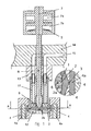
- a nozzle head 12 is arranged on a nozzle body 11 and has two outlet openings 1 pointing in opposite directions, through which valve pins 2 extend.
- the closure needles 2 are mounted axially displaceably in the nozzle head 12. At their ends 2a facing the outlet openings 1, the closure needles 2 have a cylindrical area. At their ends 2b facing away from the outlet openings 1, the closure needles 2 have an enlarged diameter area, whereby they are formed there in cross-section T-shaped.
- a rod 8, which is mounted axially displaceably in the nozzle body 11 extends.
- the rod 8 has at its nozzle head 12 facing the end of a larger diameter and wedge-shaped or pointed formed area. This pointed region forms the bottom or groove bottom of axially extending T-shaped grooves 9.
- the T-shaped ends of the closure needles 2 are arranged, so that the closure needles 2 are force-controlled by the rod 8.
- the nozzle body 11 is connected to a nozzle carrier ring 13, which in turn is connected to a distributor block 14.
- the rod 8 extends through a nozzle carrier ring 13, with which the nozzle body 11 is connected, as well as through a distributor block 14, with which the nozzle carrier ring 13 is connected.
- the rod 8 is connected to a double piston 7 of a printing cylinder, which has two chambers 7a, 7b.
- a plate spring 5 is arranged, which compressed upon actuation of the printing cylinder, that is stretched.
- the nozzle carrier ring 13 Through the distributor block 14, the nozzle carrier ring 13, the nozzle body 11 and the nozzle head 12 extends a feed channel 15 for melt.
- the feed channel 15 opens into the outlet openings 1, so that it can escape from this melt.
- the outlet openings 1 of the nozzle head 12 are each arranged opposite a connection opening 3 of a mold insert 4.
- the mold inserts 4 have cavities 4a, into which can be injected via the connection openings 3 from the outlet openings 1 emerging melt.
- valve needle 2 is substantially completely in the nozzle head 12 when the pressure cylinder is in its rest position, that is, the double piston 7 in the upper region of the chambers 7a , 7b. In this position, the connection openings 3 are completely opened so that plastic melt can enter from the outlet openings 1 via the connection openings 3 into the cavities 4a of the mold inserts 4.
- the closure needles 2 extend completely when the double piston 7 is in its operating position, ie the double piston is at the lower end of the chambers 7a, 7b through the connection openings 3 and are located slightly in the cavities 4a, that is, since the cavities 4a have been filled in the meantime with melt, slightly in the injection molded parts.
- connection openings 3 are still closed in this position.
- the closure needles 2 are no longer in the cavities 4a sondem at a distance from the cavities 4a, that is, to the located in the cavities 4a injection molded parts.
- the injection-molded parts can be removed from the mold without any fear that their surfaces will be damaged by the closure needles 2.
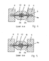
- the positive control can be inferred in particular from FIGS. 4 and 5.
- 8 T-shaped grooves are formed in the pointed end of the rod. In the grooves, the T-shaped ends 2b of the closure needles 2 run.
- valve pins 2 are in their rearmost position, so that they are almost completely within the nozzle head 12.
- the ends 2 a of the closing needle 2 facing the outlet openings 1 are located at a distance from the connection openings 3 of the mold inserts 4. In this way, melt can flow out of the outlet openings 1 of the nozzle head 12 via the connection openings 3 of the mold inserts 4 into the cavity 4a flow.
Abstract
Description
Die Erfindung betrifft eine Spritzgießdüse nach dem Oberbegriff des Anspruchs 1, mit wenigstens einer Auslassöffnung, sowie wenigstens einem zwangsgesteuerten Verschlusselement, mittels welchem eine Anbindungsöffnung einer Spritzgießform verschließbar ist.The invention relates to an injection molding nozzle according to the preamble of
Eine derartige Spritzgießdüse ist beispielsweise aus der
Des Weiteren ist eine derartige Spritzgießdüse aus der
Zum Schließen der Anbindungsöffnungen werden die Verschlussnadeln der bekannten Spritzgießdüsen soweit axial verstellt, dass sie sich in die betreffenden Anbindungsöffnungen der jeweiligen Spritzgießformen erstrecken, wodurch diese dicht verschlossen sind. Um eine einwandfreie Oberfläche der herzustellenden Spritzgussteile zu erhalten, ist es erforderlich, dass die Verschlussnadeln soweit in die Anbindungsöffnungen eindringen, dass die Stimseite der Verschlussnadeln mit der Oberfläche des betreffenden Spritzgussteils fluchtet. Dies ist in der Praxis jedoch nur äußerst schwer zu erreichen. Es sind daher aufwendige Einstellarbeiten erforderlichen.To close the connection openings, the closure needles of the known injection molding nozzles are moved axially so far that they extend into the respective attachment openings of the respective injection molds, whereby they are sealed. In order to obtain a perfect surface of the injection-molded parts to be produced, it is necessary for the closure needles to penetrate into the connection openings so far that the end face of the closure needles is flush with the surface of the injection-molded part concerned. This is in practice, however extremely difficult to reach. There are therefore complicated adjustments required.
Ragt die Verschlussnadel nicht weit genug in die Anbindungsöffnung hinein, das heißt, befindet sich die Stimfläche der Verschlussnadel in einem Abstand von der Oberfläche des Spritzgussteils, bildet sich an der Angussstelle ein kleiner Pfropfen aus. Ragt die Verschlussnadel soweit in die Anbindungsöffnung hinein, dass sie sich bis in das Spritzgussteil hineinerstreckt, können beim Entformen des Spritzgussteils Streifen auf der Oberfläche des Spritzgussteils entstehen, wodurch dieses unter Umständen nicht mehr gebraucht werden kann.Does not protrude the valve needle far enough into the connection opening, that is, is the end face of the valve needle at a distance from the surface of the injection molded part, forms at the gate a small stopper. If the valve needle protrudes into the connection opening so far that it extends into the injection-molded part, streaks can form on the surface of the injection-molded part when the injection-molded part is removed from the mold, as a result of which it may no longer be necessary.
Es ist Aufgabe der Erfindung, eine eingangs genannte Spritzgussdüse derart auszubilden, dass ohne aufwendige Justagearbeiten ein einwandfreies Spritzgussteil hergestellt werden kann.It is an object of the invention to form an injection molding nozzle mentioned at the beginning in such a way that a perfect injection-molded part can be produced without expensive adjustment work.
Die Lösung dieser Aufgabe ergibt sich aus den Merkmalen des kennzeichnenden Teils des Anspruchs 1. Vorteilhafte Weiterbildungen der Erfindung ergeben sich aus den Unteransprüchen.The solution of this problem arises from the features of the characterizing part of
Gemäß der Erfindung ist eine Spritzgießdüse mit wenigstens einer Austrittsöffnung, sowie wenigstens einem zwangsgesteuerten Verschlusselement, mittels welchem eine Anbindungsöffnung einer Spritzgießform verschließbar ist, dadurch gekennzeichnet, dass Kurzhubmittel vorhanden sind, mittels welcher das Verschlusselement um einen Kurzhub gegen die Schließrichtung des Verschlusselements verstellbar ist.According to the invention, an injection molding nozzle with at least one outlet opening and at least one positively controlled closure element, by means of which a connection opening of an injection mold is closable, characterized in that short-stroke means are present, by means of which the closure element is adjustable by a short stroke against the closing direction of the closure element.
Dadurch, dass Mittel vorhanden sind, mittels welcher das Verschlusselement um einen Kurzhub gegen die Schließrichtung des Verschlusselements verstellbar ist, lässt sich in vorteilhafter Weise erreichen, dass das Verschlusselement sich zunächst in das Spritzgussteil hineinerstreckt, wodurch ausgeschlossen ist, dass sich an der Angussstelle ein Pfropfen bildet, und danach in einem Abstand vom Spritzgussteil angeordnet ist, wodurch die Gefahr einer Streifenbildung beim Entformen nicht mehr besteht. Es lassen sich somit stets einwandfreie Spritzgussteile herstellen.By virtue of the fact that means are provided by means of which the closure element can be adjusted by a short stroke against the closing direction of the closure element, it can be achieved in an advantageous manner that the closure element initially extends into the injection molded part, whereby it is precluded that a stopper is formed at the gate forms, and is then arranged at a distance from the injection molded part, whereby the risk of streaking during demolding no longer exists. It can thus always produce perfect injection molded parts.
Durch die Kurzhubmittel kann eine genaue Justage des Verschlusselements entfallen. Denn dadurch, dass das Verschlusselement zunächst in das Spritzgussteil hineinragt und unmittelbar danach in einem Abstand vom Spritzgussteil angeordnet ist, ist es nicht mehr erforderlich, dass das Verschlusselement in seiner Schließposition eine exakte Stellung einnimmt.By Kurzhubmittel can account for a precise adjustment of the closure element. Because the fact that the closure element initially projects into the injection molded part and is immediately thereafter arranged at a distance from the injection molded part, it is no longer necessary that the closure element assumes an exact position in its closed position.
Als sehr vorteilhaft hat sich ein Kurzhub von etwa 0,05 bis 1 Millimeter, insbesondere 0,1 bis 0,5 Millimeter, vorzugsweise 0,3 Millimeter herausgestellt. Hierdurch ist einerseits eine sichere Verschließung der Angussöffnung der Spritzgießform und andererseits ein genügend großer Abstand des Verschlusselements von der Oberfläche des Spritzgussteils gewährleistet.A short stroke of about 0.05 to 1 millimeter, in particular 0.1 to 0.5 millimeter, preferably 0.3 millimeter, has proven to be very advantageous. As a result, on the one hand, a secure closure of the sprue opening of the injection mold and, on the other hand, a sufficiently large distance of the closure element from the surface of the injection molded part are ensured.
In vorteilhafter Weise ist das Verschlusselement mittels eines Antriebs betätigbar, welcher ein Rückstellelement aufweist mit einer Arbeitsposition und einer Ruheposition, welches bei nicht betätigtem Antrieb selbsttätig seine Ruheposition einnimmt. Dadurch, dass der Antrieb ein Rückstellelement aufweist, ist der Kurzhub gegen die Schließrichtung des Verschlusselements auf einfache Weise realisiert.Advantageously, the closure element can be actuated by means of a drive, which has a restoring element with a working position and a rest position, which automatically assumes its rest position when the drive is not actuated. Characterized in that the drive has a return element, the short stroke against the closing direction of the closure element is realized in a simple manner.
Betätigt der Antrieb das Verschlusselement, gelangt das Rückstellelement in seine Arbeitsposition, bei welcher das Verschlusselement in das Spritzgussteil hineinragt. Nachdem das Verschlusselement seine Endposition erreicht hat, gelangt das Rückstellelement von seiner Arbeitsposition in seine Ruheposition, wodurch das Verschlusselement einen geringen Weg gegen die Schließrichtung zurücklegt, so dass das Verschlusselement nicht mehr in das Spritzgussteil hineinragt sondern in einem Abstand vom Spritzgussteil angeordnet ist. Durch das Rückstellelement lässt sich der Kurzhub sehr einfach und sehr genau durchführen.If the drive actuates the closure element, the restoring element reaches its working position, in which the closure element projects into the injection-molded part. After the closure element has reached its end position, the return element passes from its working position to its rest position, whereby the closure element travels a short distance against the closing direction, so that the closure element no longer projects into the injection molded part but is arranged at a distance from the injection molded part. Due to the reset element, the short stroke can be very easily and very accurately.
Sehr vorteilhaft ist es, wenn das Rückstellelement als Tellerfeder ausgebildet ist, wie dies bei einer weiteren besonderen Ausführungsform der Erfindung vorgesehen ist. Ein derart ausgebildetes Rückstellelement lässt sich auf einfache Weise und damit kostengünstig herstellen und arbeitet sehr genau und zuverlässig.It when the return element is designed as a plate spring, as provided in a further particular embodiment of the invention, it is very advantageous is. Such formed resetting element can be produced in a simple manner and thus cost and works very accurate and reliable.
Das Rückstellelement kann aber auch als separates pneumatisch oder hydraulisch betriebenes Element oder ein anderes aus der Spritzgusstechnik bekanntes Verschlussnadel-Antriebssystem ausgebildet sein, wie beispielsweise ein Kurzhubzylinder. Hierdurch lässt sich bei kleiner Bauform eine große Kraft erzeugen.However, the return element can also be designed as a separate pneumatically or hydraulically operated element or another known from the injection molding technique shutter needle drive system, such as a Kurzhubzylinder. This makes it possible to generate a large force with a small design.
Bei einer weiteren besonderen Ausführungsform sind wenigstens zwei in unterschiedliche Richtungen weisende Austrittsöffnungen vorhanden, deren Verschlusselemente mittels eines Verstellmittels verstellbar sind. Der Antrieb für die Verschlusselemente kann somit auf ein gemeinsames Verstellmittel wirken. Hierdurch kann der Kurzhub gegen die Schließrichtung bei allen Verschlusselementen gleichzeitig durchgeführt werden.In a further particular embodiment, at least two outlet openings pointing in different directions are present, the closure elements of which are adjustable by means of an adjusting means. The drive for the closure elements can thus act on a common adjusting means. As a result, the short stroke can be carried out simultaneously against the closing direction in the case of all closure elements.
Des Weiteren wird dadurch, dass die Verschlusselemente mittels eines Verstellmittels verstellbar sind, in vorteilhafter Weise erreicht, dass die Bewegungen der Verschlusselemente synchron und gleichmäßig erfolgt. Das heißt, das Öffnen beziehungsweise Schließen der Anbindungsöffnungen hat bei allen Anbindungsöffnungen im Wesentlichen denselben Verlauf. Hierdurch wird ein sehr gleichmäßiges Befüllen der Spritzgießform erreicht. Dies wiederum wirkt sich sehr vorteilhaft auf die Qualität der Spritzgussteile aus.Furthermore, the fact that the closure elements are adjustable by means of an adjusting means advantageously achieves that the movements of the closure elements take place synchronously and uniformly. That is, the opening or closing of the connection openings has substantially the same course in all connection openings. As a result, a very uniform filling of the injection mold is achieved. This in turn has a very beneficial effect on the quality of the injection molded parts.
In vorteilhafter Weise sind die Verschlusselemente mittels einer Kulissenführung gesteuert. Hierdurch lässt sich eine sehr präzise Verstellung der Verschlusselemente erreichen.Advantageously, the closure elements are controlled by means of a slotted guide. This makes it possible to achieve a very precise adjustment of the closure elements.
Als besonders vorteilhaft hat sich eine Ausführungsform der Erfindung herausgestellt, bei der die Verschlusselemente als Verschlussnadeln ausgebildet sind, die sich durch die Austrittsöffnungen erstrecken und an ihren den Austrittsöffnungen entgegengesetzten Enden T-förmig ausgebildet sind und jeweils in einer längs eines Konus oder eines Keils verlaufenden T-Nut eines zentralen Stabes angeordnet sind. Eine derartige Steuerung der Verschlusselemente lässt sich einerseits relativ einfach realisieren und funktioniert andererseits sehr präzise und zuverlässig.To be particularly advantageous, an embodiment of the invention has been found in which the closure elements are formed as a closure needles which extend through the outlet openings and at their outlet openings opposite ends are T-shaped and each extending in a longitudinally of a cone or a wedge T -Nut of a central rod arranged are. On the one hand, such a control of the closure elements can be implemented relatively easily and, on the other hand, it works very precisely and reliably.
Dadurch, dass die Verschlusselemente relativ weit in die Anbindungsöffnungen einer Spritzgießform eindringen können, ist es möglich, die Verschlussnadeln an ihren sich durch die Austrittsöffnungen erstreckenden Enden zylinderförmig auszubilden. Hierdurch vereinfacht sich die Herstellung der Verschlussnadeln deutlich.Because the closure elements can penetrate relatively far into the connection openings of an injection mold, it is possible to form the closure needles in a cylindrical shape at their ends which extend through the outlet openings. As a result, the production of the closure needles simplifies significantly.
Weitere Einzelheiten, Merkmale und Vorteile der vorliegenden Erfindung ergeben sich aus der nachfolgenden Beschreibung eines besonderen Ausführungsbeispiels unter Bezugnahme auf die Zeichnung.Further details, features and advantages of the present invention will become apparent from the following description of a particular embodiment with reference to the drawings.
Es zeigt
Figur 1- eine Spritzgießdüse mit zwei seitlich angeordneten Austrittsöffnungen, durch welche sich mittels eines zentralen Stabes verstellbare Verschlussnadeln zum Verschließen einer Anbindungsöffnung einer Spritzgießform erstrecken, wobei die Verschlussnadeln in einer Position dargestellt sind, in der sie die Anbindungsöffnung nicht verschließen,
Figur 2- die in
Figur 1 dargestellte Spritzgießdüse, jedoch sind die Verschlussnadeln in einer Position dargestellt sind, in der sie die Anbindungsöffnung verschließen, Figur 3- die in
Figur 1 dargestellte Spritzgießdüse, jedoch sind die Verschlussnadeln in einer Position dargestellt, in der sie die Anbindungsöffnung verschließen, aber gegenüber der inFigur 2 dargestellten Position um einen Kurzhub verstellt, Figur 4- einen Schnitt durch die in
Figur 1 dargestellte Anordnung längs der Schnittlinie A-A und Figur 5- einen Schnitt durch die in
Figur 2 dargestellte Anordnung längs der Schnittlinie B-B.
- FIG. 1
- an injection molding nozzle with two laterally arranged outlet openings, through which extendable by means of a central rod closure needles for closing a connection opening of an injection mold, wherein the closure needles are shown in a position in which they do not close the connection opening,
- FIG. 2
- the injection molding nozzle shown in Figure 1, but the closure needles are shown in a position in which they close the connection opening,
- FIG. 3
- the injection nozzle shown in Figure 1, but the closure needles are shown in a position in which they close the connection opening, but adjusted relative to the position shown in Figure 2 by a short stroke,
- FIG. 4
- a section through the arrangement shown in Figure 1 along the section line AA and
- FIG. 5
- a section through the arrangement shown in Figure 2 along the section line BB.
Wie den Figuren 1 bis 3 entnommen werden kann, ist an einem Düsenkörper 11 ein Düsenkopf 12 angeordnet, der zwei in entgegengesetzte Richtungen weisende Auslassöffnungen 1 hat, durch welche sich Verschlussnadeln 2 erstrecken. Die Verschlussnadeln 2 sind im Düsenkopf 12 axial verschieblich gelagert. An ihren den Auslassöffnungen 1 zugewandten Enden 2a haben die Verschlussnadeln 2 einen zylindrisch ausgebildeten Bereich. An ihren den Auslassöffnungen 1 abgewandten Enden 2b haben die Verschlussnadeln 2 einen im Durchmesser vergrößerten Bereich, wodurch sie dort im Querschnitt T-förmig ausgebildet sind.As can be seen in FIGS. 1 to 3, a
Durch den Düsenkörper 11 erstreckt sich ein Stab 8, welcher im Düsenkörper 11 axial verschieblich gelagert ist. Der Stab 8 hat an seinem dem Düsenkopf 12 zugewandten Ende einen im Durchmesser vergrößerten und keilförmig beziehungsweise spitz ausgebildeten Bereich. Dieser spitz ausgebildete Bereich bildet den Boden beziehungsweise Nutgrund axial verlaufender T-förmig ausgebildeter Nuten 9. In den Nuten 9 sind die T-förmig ausgebildeten Enden der Verschlussnadeln 2 angeordnet, so dass die Verschlussnadeln 2 durch den Stab 8 zwangsgesteuert sind.Through the
Der Düsenkörper 11 ist mit einem Düsenträgerring 13 verbunden, der seinerseits mit einem Verteilerblock 14 verbunden ist.The
Der Stab 8 erstreckt sich durch einen Düsenträgerring 13, mit dem der Düsenkörper 11 verbunden ist, sowie durch einen Verteilerblock 14, mit dem der Düsenträgerring 13 verbunden ist. An seinem dem Düsenkopf 12 abgewandten Ende ist der Stab 8 mit einem Doppelkolben 7 eines Druckzylinders verbunden, der zwei Kammern 7a, 7b aufweist. In der unteren Kammer 7b ist eine Tellerfeder 5 angeordnet, welche bei Betätigung des Druckzylinders zusammengedrückt, das heißt gespannt wird.The
Durch den Verteilerblock 14, den Düsenträgerring 13, den Düsenkörper 11 sowie den Düsenkopf 12 erstreckt sich ein Zuführkanal 15 für Schmelze. Der Zuführkanal 15 mündet in den Auslassöffnungen 1, so dass aus diesen Schmelze austreten kann.Through the
Die Auslassöffnungen 1 des Düsenkopfs 12 sind jeweils gegenüber einer Anbindungsöffnung 3 eines Formeneinsatzes 4 angeordnet. Die Formeinsätze 4 weisen Hohlräume 4a auf, in welche über die Anbindungsöffnungen 3 aus den Auslassöffnungen 1 austretende Schmelze eingespritzt werden kann.The
Wie insbesondere der in einem Kreis dargestellten vergrößerten Einzelheit der Figur 1 entnommen werden kann, befindet sich die Verschlussnadel 2 im Wesentlichen vollständig im Düsenkopf 12, wenn sich der Druckzylinder in seiner Ruheposition befindet, das heißt, sich der Doppelkolben 7 im oberen Bereich der Kammern 7a, 7b befindet. In dieser Stellung sind die Anbindungsöffnungen 3 vollständig geöffnet, so dass Kunststoffschmelze aus den Auslassöffnungen 1 über die Anbindungsöffnungen 3 in die Hohlräume 4a der Formeinsätze 4 eintreten kann.As can be seen in particular the enlarged detail shown in a circle of Figure 1, the
Nachdem auf den Druckzylinder Druck gegeben wird, bewegt sich der Doppelkolben 7 in den unteren Bereich der Kammern 7a, 7b. Hierdurch wird der Stab 8 in den Düsenkopf 12 geschoben, wodurch sich die Verschlussnadeln 2 in Richtung der Anbindungsöffnungen 3 verstellen.After pressure is applied to the pressure cylinder, the
Wie insbesondere der in einem Kreis dargestellten vergrößerten Einzelheit der Figur 2 entnommen werden kann, erstrecken sich die Verschlussnadeln 2 dann, wenn sich der Doppelkolben 7 in seiner Betriebsstellung befindet, das heißt, sich der Doppelkolben am unteren Ende der Kammern 7a, 7b befindet, vollständig durch die Anbindungsöffnungen 3 und befinden sich geringfügig in den Hohlräumen 4a, das heißt, da die Hohlräume 4a zwischenzeitlich mit Schmelze gefüllt wurden, geringfügig in den Spritzgussteilen.As can be seen in particular from the enlarged detail of FIG. 2 shown in a circle, the closure needles 2 extend completely when the
Nachdem der Doppelkolben 7 das untere Ende der Kammern 7a, 7b erreicht hat, wird der Druckzylinder nicht mehr mit Druck beaufschlagt. Hierdurch kann sich die Blattfeder 5 entspannen, wodurch sich der Doppelkolben 7 und mit ihm der Stab 8 etwas nach oben bewegt.After the
Bedingt durch die Zwangssteuerung der Verschlussnadeln 2 werden diese gegen die Schließrichtung 6 der Verschlussnadeln 2 etwas zurückbewegt. Diese Position ist in Figur 3 dargestellt.Due to the forced control of the closure needles 2, these are moved back slightly against the closing
Wie insbesondere der in einem Kreis dargestellten vergrößerten Einzelheit der Figur 3 entnommen werden kann, sind in dieser Position die Anbindungsöffnungen 3 immer noch verschlossen. Die Verschlussnadeln 2 befinden sich jedoch nicht mehr in den Hohlräumen 4a sondem in einem Abstand zu den Hohlräumen 4a, das heißt zu den sich in den Hohlräumen 4a befindlichen Spritzgussteilen. Hierdurch können die Spritzgussteile entformt werden, ohne dass zu befürchten ist, dass ihre Oberflächen durch die Verschlussnadeln 2 beschädigt werden.As can be seen in particular the enlarged detail shown in a circle of Figure 3, the
Die Zwangssteuerung lässt sich insbesondere den Figuren 4 und 5 entnehmen. Wie den Figuren 4 und 5 entnommen werden kann, sind in dem spitz verlaufenden Ende des Stabes 8 T-förmige Nuten ausgebildet. In den Nuten verlaufen die T-förmig ausgebildeten Enden 2b der Verschlussnadeln 2.The positive control can be inferred in particular from FIGS. 4 and 5. As can be seen in Figures 4 and 5, 8 T-shaped grooves are formed in the pointed end of the rod. In the grooves, the T-shaped
Bei der in Figur 4 dargestellten Position des Stabes 8, die der in Figur 1 dargestellten Position des Stabes 8 entspricht, sind die Verschlussnadeln 2 in ihrer hintersten Stellung, so dass sie sich nahezu vollständig innerhalb des Düsenkopfes 12 befinden. Insbesondere befinden sich die den Auslassöffnungen 1 zugewandten Enden 2a der Verschlussnadein 2 in einem Abstand von den Anbindungsöffnungen 3 der Formeinsätze 4. Hierdurch kann Schmelze aus den Auslassöffnungen 1 des Düsenkopfes 12 über die Anbindungsöffnungen 3 der Formeinsätze 4 in den Hohlraum 4a fließen.In the position of the
Bei der in Figur 5 dargestellten Position des Stabes 8, der der in Figur 2 dargestellten Position des Stabes 8 entspricht, befinden sich die Verschlussnadeln 2 in ihrer vorderen Stellung, wodurch sich die den Auslassöffnungen 1 zugewandten Enden 2a der Verschlussnadeln 2 in den Anbindungsöffnungen 3 befinden. Hierdurch sind diese verschlossen, so dass Schmelze weder in die Hohlräume 4a der Formeinsätze 4 eintreten noch aus diesen austreten kann.In the position of the
Claims (8)
dadurch gekennzeichnet,
dass Kurzhubmittel (5) vorhanden sind, mittels welcher das Verschlusselement (2) um einen Kurzhub gegen die Schließrichtung (6) des Verschlusselements (2) verstellbar ist.Injection molding nozzle with at least one outlet opening (1) and at least one positively controlled closure element (2), by means of which a connection opening (3) of an injection mold (4) can be closed
characterized,
that short-stroke means (5) are provided, by means of which the closure element (2) is adjustable by a short stroke against the closing direction (6) of the closure element (2).
dadurch gekennzeichnet,
dass der Kurzhub etwa 0,05 bis 1 Millimeter, insbesondere 0,1 bis 0,5 Millimeter, vorzugsweise 0,3 Millimeter beträgt.Injection molding nozzle according to claim 1,
characterized,
that the short stroke is about 0.05 to 1 millimeter, in particular 0.1 to 0.5 millimeters, preferably 0.3 millimeters.
dadurch gekennzeichnet,
dass das Verschlusselement (2) mittels eines Antriebs (7) betätigbar ist, welcher ein als Rückstellelement (5) ausgebildetes Kurzhubmittel mit einer Arbeitsposition und einer Ruheposition aufweist, welches bei nicht betätigtem Antrieb (7) selbsttätig seine Ruheposition einnimmt.Injection molding nozzle according to claim 1 or 2,
characterized,
in that the closure element (2) can be actuated by means of a drive (7) which has a short-stroke means configured as a restoring element (5) with a working position and a rest position which automatically assumes its rest position when the drive (7) is not actuated.
dadurch gekennzeichnet,
dass das Rückstellelement (5) als Tellerfeder ausgebildet ist.Injection molding nozzle according to claim 3,
characterized,
that the return element (5) is designed as a plate spring.
dadurch gekennzeichnet,
dass wenigstens zwei in unterschiedliche Richtungen weisende Auslassöffnungen (1) vorhanden sind, deren Verschlusselemente (2) mittels eines Verstellmittels (8) verstellbar sind.Injection molding nozzle according to one of claims 1 to 4,
characterized,
in that at least two outlet openings (1) pointing in different directions are present, whose closure elements (2) are adjustable by means of an adjustment means (8).
dadurch gekennzeichnet,
dass die Verschlusselemente (2) mittels einer Kulissenführung (9) gesteuert sind.Injection molding nozzle according to one of claims 1 to 5,
characterized,
that the closure elements are controlled (2) by means of a link guide (9).
dadurch gekennzeichnet,
dass die Verschlusselemente (2) als Verschlussnadeln ausgebildet sind, die sich durch die Auslassöffnungen (1) erstrecken und an ihren den Austrittsöffnungen (1) entgegengesetzten Enden (2b) T-förmig ausgebildet sind und jeweils in einer längs eines Konus verlaufenden T-Nut (9) eines zentralen Stabes (8) angeordnet sind.Injection molding nozzle according to one of claims 1 to 6,
characterized,
in that the closure elements (2) are designed as closure needles which extend through the outlet openings (1) and are T-shaped at their ends (2b) opposite the outlet openings (1) and in each case in a T-slot extending along a cone ( 9) of a central rod (8) are arranged.
dadurch gekennzeichnet,
dass die Verschlussnadeln (2) an ihren sich durch die Auslassöffnungen (1) erstreckenden Enden (2a) zylinderförmig ausgebildet sind.Injection molding nozzle according to claim 7,
characterized,
that the closure needles (2) are cylindrical in their extending through the outlet openings (1) ends (2a).
Priority Applications (1)
| Application Number | Priority Date | Filing Date | Title |
|---|---|---|---|
| PL06006648T PL1712341T3 (en) | 2005-04-15 | 2006-03-30 | Injection nozzle with two outlet orifices |
Applications Claiming Priority (1)
| Application Number | Priority Date | Filing Date | Title |
|---|---|---|---|
| DE102005017413A DE102005017413B4 (en) | 2005-04-15 | 2005-04-15 | Injection nozzle with two outlet openings |
Publications (3)
| Publication Number | Publication Date |
|---|---|
| EP1712341A2 true EP1712341A2 (en) | 2006-10-18 |
| EP1712341A3 EP1712341A3 (en) | 2007-01-03 |
| EP1712341B1 EP1712341B1 (en) | 2008-07-23 |
Family
ID=36586033
Family Applications (1)
| Application Number | Title | Priority Date | Filing Date |
|---|---|---|---|
| EP06006648A Active EP1712341B1 (en) | 2005-04-15 | 2006-03-30 | Injection nozzle with two outlet orifices |
Country Status (11)
| Country | Link |
|---|---|
| US (2) | US20060257521A1 (en) |
| EP (1) | EP1712341B1 (en) |
| JP (1) | JP4404869B2 (en) |
| AT (1) | ATE402003T1 (en) |
| CA (1) | CA2541792C (en) |
| DE (2) | DE102005017413B4 (en) |
| DK (1) | DK1712341T3 (en) |
| ES (1) | ES2310868T3 (en) |
| PL (1) | PL1712341T3 (en) |
| PT (1) | PT1712341E (en) |
| RS (1) | RS50623B (en) |
Cited By (3)
| Publication number | Priority date | Publication date | Assignee | Title |
|---|---|---|---|---|
| WO2013127524A1 (en) * | 2012-02-27 | 2013-09-06 | Otto Männer Innovation GmbH | Hot channel system |
| EP3363613A1 (en) * | 2017-02-17 | 2018-08-22 | Otto Männer GmbH | Hot runner injection nozzle and drive train |
| EP3611005A1 (en) * | 2018-08-14 | 2020-02-19 | Otto Männer GmbH | Hot runner injection nozzle and drive train |
Families Citing this family (12)
| Publication number | Priority date | Publication date | Assignee | Title |
|---|---|---|---|---|
| US7547208B2 (en) * | 2006-06-16 | 2009-06-16 | Mold-Masters (2007) Limited | Individual cavity shut-off valve for an injection molding apparatus |
| US7803306B2 (en) * | 2006-06-16 | 2010-09-28 | Mold-Masters (2007) Limited | Individual cavity shut-off valve for an injection molding apparatus |
| DE602007004819D1 (en) * | 2006-12-22 | 2010-04-01 | Mold Masters 2007 Ltd | Injection molding device with lateral sprue openings |
| US7658606B2 (en) * | 2006-12-22 | 2010-02-09 | Mold-Masters (2007) Limited | Edge gated injection molding apparatus |
| ATE544573T1 (en) * | 2006-12-29 | 2012-02-15 | Mold Masters 2007 Ltd | INJECTION MOLDING DEVICE WITH SIDE GATE OPENING |
| EP2390075A1 (en) * | 2010-05-31 | 2011-11-30 | Electrolux Home Products Corporation N.V. | Method and molding equipment for making a plastic wheel, and wheel thus obtained |
| EP2615933A4 (en) * | 2010-09-13 | 2014-05-21 | Husky Injection Molding | Mold-tool system having actuator assembly including piston assembly and flexible diaphragm assembly |
| JP2015063110A (en) * | 2013-09-26 | 2015-04-09 | 世紀株式会社 | Apparatus and method for injection molding using valve pin operated by double piston mechanism |
| JP6565929B2 (en) * | 2014-11-11 | 2019-08-28 | サンスター スイス エスエー | Interdental cleaning tool manufacturing method |
| WO2016081334A1 (en) | 2014-11-17 | 2016-05-26 | Husky Injection Modling Systems Ltd. | Hot runner nozzle with a gate pressure equalizer |
| KR101760571B1 (en) * | 2015-09-04 | 2017-07-31 | 허남욱 | Valve apparatus for side gate of a hot runner injection mold |
| WO2017088044A1 (en) * | 2015-11-23 | 2017-06-01 | Husky Injection Molding Systems Ltd. | Valve stem actuation |
Citations (4)
| Publication number | Priority date | Publication date | Assignee | Title |
|---|---|---|---|---|
| DE8107987U1 (en) * | 1981-03-19 | 1981-08-13 | F-T-Fertigungstechnik Gmbh & Co Kg, 6806 Viernheim | HOT TUBE NOZZLE WITH NEEDLE VALVE |
| US5334010A (en) * | 1993-12-13 | 1994-08-02 | Mold-Masters Limited | Valve gated injection molding apparatus with a spring in the piston |
| EP0614744A1 (en) * | 1993-02-25 | 1994-09-14 | Sony Electronics Inc. | Molding devices |
| US20040009259A1 (en) * | 2002-07-10 | 2004-01-15 | Otto Manner Heisskanalsysteme Gmbh & Co. Kg | Injection molding nozzle for plastic with at least two outlet openings |
Family Cites Families (1)
| Publication number | Priority date | Publication date | Assignee | Title |
|---|---|---|---|---|
| DE3843035A1 (en) * | 1988-12-21 | 1990-06-28 | Otto Maenner | NEEDLE SHUTTER NOZZLE FOR INJECTION MOLDS |
-
2005
- 2005-04-15 DE DE102005017413A patent/DE102005017413B4/en not_active Expired - Fee Related
-
2006
- 2006-03-30 DE DE502006001160T patent/DE502006001160D1/en active Active
- 2006-03-30 AT AT06006648T patent/ATE402003T1/en active
- 2006-03-30 EP EP06006648A patent/EP1712341B1/en active Active
- 2006-03-30 ES ES06006648T patent/ES2310868T3/en active Active
- 2006-03-30 PL PL06006648T patent/PL1712341T3/en unknown
- 2006-03-30 RS RSP-2008/0472A patent/RS50623B/en unknown
- 2006-03-30 DK DK06006648T patent/DK1712341T3/en active
- 2006-03-30 PT PT06006648T patent/PT1712341E/en unknown
- 2006-04-05 CA CA002541792A patent/CA2541792C/en not_active Expired - Fee Related
- 2006-04-13 US US11/403,431 patent/US20060257521A1/en not_active Abandoned
- 2006-04-17 JP JP2006113677A patent/JP4404869B2/en not_active Expired - Fee Related
- 2006-05-19 US US11/437,224 patent/US7470123B2/en active Active
Patent Citations (4)
| Publication number | Priority date | Publication date | Assignee | Title |
|---|---|---|---|---|
| DE8107987U1 (en) * | 1981-03-19 | 1981-08-13 | F-T-Fertigungstechnik Gmbh & Co Kg, 6806 Viernheim | HOT TUBE NOZZLE WITH NEEDLE VALVE |
| EP0614744A1 (en) * | 1993-02-25 | 1994-09-14 | Sony Electronics Inc. | Molding devices |
| US5334010A (en) * | 1993-12-13 | 1994-08-02 | Mold-Masters Limited | Valve gated injection molding apparatus with a spring in the piston |
| US20040009259A1 (en) * | 2002-07-10 | 2004-01-15 | Otto Manner Heisskanalsysteme Gmbh & Co. Kg | Injection molding nozzle for plastic with at least two outlet openings |
Cited By (5)
| Publication number | Priority date | Publication date | Assignee | Title |
|---|---|---|---|---|
| WO2013127524A1 (en) * | 2012-02-27 | 2013-09-06 | Otto Männer Innovation GmbH | Hot channel system |
| US9452557B2 (en) | 2012-02-27 | 2016-09-27 | Otto Männer Innovation GmbH | Hot runner system |
| EP3363613A1 (en) * | 2017-02-17 | 2018-08-22 | Otto Männer GmbH | Hot runner injection nozzle and drive train |
| EP3611005A1 (en) * | 2018-08-14 | 2020-02-19 | Otto Männer GmbH | Hot runner injection nozzle and drive train |
| CN110815730A (en) * | 2018-08-14 | 2020-02-21 | 奥托门纳有限责任公司 | Hot runner injection nozzle and drive train |
Also Published As
| Publication number | Publication date |
|---|---|
| EP1712341B1 (en) | 2008-07-23 |
| US20060233911A1 (en) | 2006-10-19 |
| ES2310868T3 (en) | 2009-01-16 |
| PT1712341E (en) | 2008-09-26 |
| PL1712341T3 (en) | 2009-01-30 |
| ATE402003T1 (en) | 2008-08-15 |
| DE502006001160D1 (en) | 2008-09-04 |
| JP2006297933A (en) | 2006-11-02 |
| US7470123B2 (en) | 2008-12-30 |
| RS50623B (en) | 2010-06-30 |
| DK1712341T3 (en) | 2008-11-10 |
| CA2541792A1 (en) | 2006-10-15 |
| JP4404869B2 (en) | 2010-01-27 |
| CA2541792C (en) | 2009-12-08 |
| EP1712341A3 (en) | 2007-01-03 |
| DE102005017413A1 (en) | 2006-10-19 |
| DE102005017413B4 (en) | 2008-06-26 |
| US20060257521A1 (en) | 2006-11-16 |
Similar Documents
| Publication | Publication Date | Title |
|---|---|---|
| EP1712341B1 (en) | Injection nozzle with two outlet orifices | |
| DE2519932C2 (en) | Shut-off nozzle for injecting molten plastic | |
| AT395693B (en) | Transfer moulding installation | |
| DE102009012082B3 (en) | Method for injection molding, in particular for cascade injection molding, and apparatus for carrying out the method | |
| AT395555B (en) | DEVICE FOR INJECTION MOLDING OBJECTS CONTAINING PLASTIC | |
| DE3245571A1 (en) | Needle shut-off nozzle for injection moulds | |
| EP0310914A2 (en) | Method of injection moulding formed parts of thermoplastic resins, and for carrying out this method | |
| DE4235673A1 (en) | MOLDING DEVICE FOR PRODUCING RESIN MOLDINGS | |
| EP0781640B1 (en) | Heated needle valve nozzle | |
| EP0363948A1 (en) | Nozzle for injection-moulding machines | |
| EP0467129B1 (en) | Nozzle for injection moulding machines | |
| DE102012025117B4 (en) | Casting tool for producing a component in a gas-assisted injection molding process | |
| DE2009006A1 (en) | Closing nozzle for injection molding machines | |
| DE19807567C2 (en) | Die casting machine | |
| WO2004071742A1 (en) | Method for producing mould parts by injection and a plugged needle nozzle for an injection mould | |
| DE3336203A1 (en) | Injection or compression mould for processing plastics materials | |
| DE10039864C5 (en) | injection molding nozzle | |
| DE1009484B (en) | Hydraulic press for processing plastic masses and for drawing sheet metal | |
| DE1168062B (en) | Method for operating a nozzle closing device for injection molding machines for processing thermoplastic materials and nozzle closing device for carrying out the process | |
| DE112014005406T5 (en) | Hot runner injection molding machine and method for side injection with independent valve pins | |
| WO2013013925A2 (en) | Injection head and ejector of an injection device | |
| DE3314960A1 (en) | DEVICE FOR PRODUCING HOLLOW GLASS BODIES | |
| DE3619260C1 (en) | Device for producing mouldings from plastics | |
| DE3709557C1 (en) | Device for forming a plastic reaction mixture | |
| DE2653930A1 (en) | Injector for foam plastics moulding - compressed air works on piston with end sealing plug and central by=pass |
Legal Events
| Date | Code | Title | Description |
|---|---|---|---|
| PUAI | Public reference made under article 153(3) epc to a published international application that has entered the european phase |
Free format text: ORIGINAL CODE: 0009012 |
|
| AK | Designated contracting states |
Kind code of ref document: A2 Designated state(s): AT BE BG CH CY CZ DE DK EE ES FI FR GB GR HU IE IS IT LI LT LU LV MC NL PL PT RO SE SI SK TR |
|
| AX | Request for extension of the european patent |
Extension state: AL BA HR MK YU |
|
| PUAL | Search report despatched |
Free format text: ORIGINAL CODE: 0009013 |
|
| AK | Designated contracting states |
Kind code of ref document: A3 Designated state(s): AT BE BG CH CY CZ DE DK EE ES FI FR GB GR HU IE IS IT LI LT LU LV MC NL PL PT RO SE SI SK TR |
|
| AX | Request for extension of the european patent |
Extension state: AL BA HR MK YU |
|
| 17P | Request for examination filed |
Effective date: 20070703 |
|
| AKX | Designation fees paid |
Designated state(s): AT BE BG CH CY CZ DE DK EE ES FI FR GB GR HU IE IS IT LI LT LU LV MC NL PL PT RO SE SI SK TR |
|
| AXX | Extension fees paid |
Extension state: YU Payment date: 20070703 |
|
| GRAP | Despatch of communication of intention to grant a patent |
Free format text: ORIGINAL CODE: EPIDOSNIGR1 |
|
| GRAS | Grant fee paid |
Free format text: ORIGINAL CODE: EPIDOSNIGR3 |
|
| GRAA | (expected) grant |
Free format text: ORIGINAL CODE: 0009210 |
|
| AK | Designated contracting states |
Kind code of ref document: B1 Designated state(s): AT BE BG CH CY CZ DE DK EE ES FI FR GB GR HU IE IS IT LI LT LU LV MC NL PL PT RO SE SI SK TR |
|
| AX | Request for extension of the european patent |
Extension state: YU |
|
| REG | Reference to a national code |
Ref country code: GB Ref legal event code: FG4D Free format text: NOT ENGLISH |
|
| REG | Reference to a national code |
Ref country code: CH Ref legal event code: EP |
|
| REG | Reference to a national code |
Ref country code: CH Ref legal event code: NV Representative=s name: RIEDERER HASLER & PARTNER PATENTANWAELTE AG |
|
| REG | Reference to a national code |
Ref country code: IE Ref legal event code: FG4D Free format text: LANGUAGE OF EP DOCUMENT: GERMAN |
|
| REF | Corresponds to: |
Ref document number: 502006001160 Country of ref document: DE Date of ref document: 20080904 Kind code of ref document: P |
|
| REG | Reference to a national code |
Ref country code: PT Ref legal event code: SC4A Free format text: AVAILABILITY OF NATIONAL TRANSLATION Effective date: 20080915 |
|
| REG | Reference to a national code |
Ref country code: GR Ref legal event code: EP Ref document number: 20080402446 Country of ref document: GR |
|
| REG | Reference to a national code |
Ref country code: DK Ref legal event code: T3 |
|
| REG | Reference to a national code |
Ref country code: SE Ref legal event code: TRGR |
|
| REG | Reference to a national code |
Ref country code: ES Ref legal event code: FG2A Ref document number: 2310868 Country of ref document: ES Kind code of ref document: T3 |
|
| REG | Reference to a national code |
Ref country code: HU Ref legal event code: AG4A Ref document number: E004095 Country of ref document: HU |
|
| PG25 | Lapsed in a contracting state [announced via postgrant information from national office to epo] |
Ref country code: IS Free format text: LAPSE BECAUSE OF FAILURE TO SUBMIT A TRANSLATION OF THE DESCRIPTION OR TO PAY THE FEE WITHIN THE PRESCRIBED TIME-LIMIT Effective date: 20081123 Ref country code: LT Free format text: LAPSE BECAUSE OF FAILURE TO SUBMIT A TRANSLATION OF THE DESCRIPTION OR TO PAY THE FEE WITHIN THE PRESCRIBED TIME-LIMIT Effective date: 20080723 |
|
| REG | Reference to a national code |
Ref country code: PL Ref legal event code: T3 |
|
| PG25 | Lapsed in a contracting state [announced via postgrant information from national office to epo] |
Ref country code: BG Free format text: LAPSE BECAUSE OF FAILURE TO SUBMIT A TRANSLATION OF THE DESCRIPTION OR TO PAY THE FEE WITHIN THE PRESCRIBED TIME-LIMIT Effective date: 20081023 Ref country code: SI Free format text: LAPSE BECAUSE OF FAILURE TO SUBMIT A TRANSLATION OF THE DESCRIPTION OR TO PAY THE FEE WITHIN THE PRESCRIBED TIME-LIMIT Effective date: 20080723 Ref country code: LV Free format text: LAPSE BECAUSE OF FAILURE TO SUBMIT A TRANSLATION OF THE DESCRIPTION OR TO PAY THE FEE WITHIN THE PRESCRIBED TIME-LIMIT Effective date: 20080723 |
|
| PG25 | Lapsed in a contracting state [announced via postgrant information from national office to epo] |
Ref country code: EE Free format text: LAPSE BECAUSE OF FAILURE TO SUBMIT A TRANSLATION OF THE DESCRIPTION OR TO PAY THE FEE WITHIN THE PRESCRIBED TIME-LIMIT Effective date: 20080723 |
|
| PG25 | Lapsed in a contracting state [announced via postgrant information from national office to epo] |
Ref country code: RO Free format text: LAPSE BECAUSE OF FAILURE TO SUBMIT A TRANSLATION OF THE DESCRIPTION OR TO PAY THE FEE WITHIN THE PRESCRIBED TIME-LIMIT Effective date: 20080723 Ref country code: SK Free format text: LAPSE BECAUSE OF FAILURE TO SUBMIT A TRANSLATION OF THE DESCRIPTION OR TO PAY THE FEE WITHIN THE PRESCRIBED TIME-LIMIT Effective date: 20080723 |
|
| PLBE | No opposition filed within time limit |
Free format text: ORIGINAL CODE: 0009261 |
|
| STAA | Information on the status of an ep patent application or granted ep patent |
Free format text: STATUS: NO OPPOSITION FILED WITHIN TIME LIMIT |
|
| 26N | No opposition filed |
Effective date: 20090424 |
|
| PG25 | Lapsed in a contracting state [announced via postgrant information from national office to epo] |
Ref country code: MC Free format text: LAPSE BECAUSE OF NON-PAYMENT OF DUE FEES Effective date: 20090331 |
|
| PGFP | Annual fee paid to national office [announced via postgrant information from national office to epo] |
Ref country code: IE Payment date: 20110322 Year of fee payment: 6 Ref country code: HU Payment date: 20110330 Year of fee payment: 6 Ref country code: DK Payment date: 20110328 Year of fee payment: 6 |
|
| PGFP | Annual fee paid to national office [announced via postgrant information from national office to epo] |
Ref country code: NL Payment date: 20110328 Year of fee payment: 6 Ref country code: SE Payment date: 20110325 Year of fee payment: 6 Ref country code: PL Payment date: 20110224 Year of fee payment: 6 Ref country code: TR Payment date: 20110324 Year of fee payment: 6 Ref country code: LU Payment date: 20110325 Year of fee payment: 6 Ref country code: FI Payment date: 20110323 Year of fee payment: 6 Ref country code: CZ Payment date: 20110321 Year of fee payment: 6 |
|
| PGFP | Annual fee paid to national office [announced via postgrant information from national office to epo] |
Ref country code: GR Payment date: 20110330 Year of fee payment: 6 |
|
| PGFP | Annual fee paid to national office [announced via postgrant information from national office to epo] |
Ref country code: BE Payment date: 20110328 Year of fee payment: 6 |
|
| PG25 | Lapsed in a contracting state [announced via postgrant information from national office to epo] |
Ref country code: CY Free format text: LAPSE BECAUSE OF FAILURE TO SUBMIT A TRANSLATION OF THE DESCRIPTION OR TO PAY THE FEE WITHIN THE PRESCRIBED TIME-LIMIT Effective date: 20080723 |
|
| REG | Reference to a national code |
Ref country code: DE Ref legal event code: R082 Ref document number: 502006001160 Country of ref document: DE Representative=s name: PRUEFER & PARTNER GBR, DE Ref country code: DE Ref legal event code: R082 Ref document number: 502006001160 Country of ref document: DE Representative=s name: PRUEFER & PARTNER MBB PATENTANWAELTE RECHTSANW, DE Ref country code: DE Ref legal event code: R082 Ref document number: 502006001160 Country of ref document: DE Representative=s name: ELC RECHTSANWAELTE DUNKEL KRAEMER SCHAELLIG PA, DE |
|
| BERE | Be: lapsed |
Owner name: OTTO MANNER INNOVATION G.M.B.H. Effective date: 20120331 |
|
| REG | Reference to a national code |
Ref country code: NL Ref legal event code: V1 Effective date: 20121001 |
|
| REG | Reference to a national code |
Ref country code: SE Ref legal event code: EUG |
|
| PG25 | Lapsed in a contracting state [announced via postgrant information from national office to epo] |
Ref country code: SE Free format text: LAPSE BECAUSE OF NON-PAYMENT OF DUE FEES Effective date: 20120331 Ref country code: FI Free format text: LAPSE BECAUSE OF NON-PAYMENT OF DUE FEES Effective date: 20120330 |
|
| REG | Reference to a national code |
Ref country code: DK Ref legal event code: EBP |
|
| REG | Reference to a national code |
Ref country code: GR Ref legal event code: ML Ref document number: 20080402446 Country of ref document: GR Effective date: 20121008 |
|
| REG | Reference to a national code |
Ref country code: IE Ref legal event code: MM4A |
|
| PG25 | Lapsed in a contracting state [announced via postgrant information from national office to epo] |
Ref country code: BE Free format text: LAPSE BECAUSE OF NON-PAYMENT OF DUE FEES Effective date: 20120331 Ref country code: CZ Free format text: LAPSE BECAUSE OF NON-PAYMENT OF DUE FEES Effective date: 20120330 Ref country code: HU Free format text: LAPSE BECAUSE OF NON-PAYMENT OF DUE FEES Effective date: 20120331 Ref country code: IE Free format text: LAPSE BECAUSE OF NON-PAYMENT OF DUE FEES Effective date: 20120330 |
|
| PG25 | Lapsed in a contracting state [announced via postgrant information from national office to epo] |
Ref country code: GR Free format text: LAPSE BECAUSE OF NON-PAYMENT OF DUE FEES Effective date: 20121008 |
|
| PG25 | Lapsed in a contracting state [announced via postgrant information from national office to epo] |
Ref country code: NL Free format text: LAPSE BECAUSE OF NON-PAYMENT OF DUE FEES Effective date: 20121001 |
|
| PG25 | Lapsed in a contracting state [announced via postgrant information from national office to epo] |
Ref country code: DK Free format text: LAPSE BECAUSE OF NON-PAYMENT OF DUE FEES Effective date: 20120331 |
|
| PG25 | Lapsed in a contracting state [announced via postgrant information from national office to epo] |
Ref country code: PL Free format text: LAPSE BECAUSE OF NON-PAYMENT OF DUE FEES Effective date: 20120330 |
|
| REG | Reference to a national code |
Ref country code: PL Ref legal event code: LAPE |
|
| PG25 | Lapsed in a contracting state [announced via postgrant information from national office to epo] |
Ref country code: LU Free format text: LAPSE BECAUSE OF NON-PAYMENT OF DUE FEES Effective date: 20120330 Ref country code: TR Free format text: LAPSE BECAUSE OF NON-PAYMENT OF DUE FEES Effective date: 20120330 |
|
| REG | Reference to a national code |
Ref country code: DE Ref legal event code: R082 Ref document number: 502006001160 Country of ref document: DE Representative=s name: PRUEFER & PARTNER GBR, DE Ref country code: DE Ref legal event code: R082 Ref document number: 502006001160 Country of ref document: DE Representative=s name: PRUEFER & PARTNER MBB PATENTANWAELTE RECHTSANW, DE Ref country code: DE Ref legal event code: R082 Ref document number: 502006001160 Country of ref document: DE Representative=s name: ELC RECHTSANWAELTE DUNKEL KRAEMER SCHAELLIG PA, DE |
|
| PGFP | Annual fee paid to national office [announced via postgrant information from national office to epo] |
Ref country code: PT Payment date: 20150320 Year of fee payment: 10 Ref country code: ES Payment date: 20150325 Year of fee payment: 10 |
|
| PGFP | Annual fee paid to national office [announced via postgrant information from national office to epo] |
Ref country code: GB Payment date: 20150324 Year of fee payment: 10 Ref country code: AT Payment date: 20150325 Year of fee payment: 10 |
|
| REG | Reference to a national code |
Ref country code: FR Ref legal event code: PLFP Year of fee payment: 11 |
|
| REG | Reference to a national code |
Ref country code: DE Ref legal event code: R082 Ref document number: 502006001160 Country of ref document: DE Representative=s name: ELC RECHTSANWAELTE DUNKEL KRAEMER SCHAELLIG PA, DE |
|
| REG | Reference to a national code |
Ref country code: AT Ref legal event code: MM01 Ref document number: 402003 Country of ref document: AT Kind code of ref document: T Effective date: 20160330 |
|
| GBPC | Gb: european patent ceased through non-payment of renewal fee |
Effective date: 20160330 |
|
| PG25 | Lapsed in a contracting state [announced via postgrant information from national office to epo] |
Ref country code: PT Free format text: LAPSE BECAUSE OF NON-PAYMENT OF DUE FEES Effective date: 20160930 |
|
| PG25 | Lapsed in a contracting state [announced via postgrant information from national office to epo] |
Ref country code: GB Free format text: LAPSE BECAUSE OF NON-PAYMENT OF DUE FEES Effective date: 20160330 |
|
| PG25 | Lapsed in a contracting state [announced via postgrant information from national office to epo] |
Ref country code: AT Free format text: LAPSE BECAUSE OF NON-PAYMENT OF DUE FEES Effective date: 20160330 |
|
| REG | Reference to a national code |
Ref country code: FR Ref legal event code: PLFP Year of fee payment: 12 |
|
| REG | Reference to a national code |
Ref country code: FR Ref legal event code: PLFP Year of fee payment: 13 |
|
| PG25 | Lapsed in a contracting state [announced via postgrant information from national office to epo] |
Ref country code: ES Free format text: LAPSE BECAUSE OF NON-PAYMENT OF DUE FEES Effective date: 20160331 |
|
| REG | Reference to a national code |
Ref country code: ES Ref legal event code: FD2A Effective date: 20180627 |
|
| REG | Reference to a national code |
Ref country code: CH Ref legal event code: PL |
|
| PG25 | Lapsed in a contracting state [announced via postgrant information from national office to epo] |
Ref country code: CH Free format text: LAPSE BECAUSE OF NON-PAYMENT OF DUE FEES Effective date: 20200331 Ref country code: LI Free format text: LAPSE BECAUSE OF NON-PAYMENT OF DUE FEES Effective date: 20200331 |
|
| PGFP | Annual fee paid to national office [announced via postgrant information from national office to epo] |
Ref country code: FR Payment date: 20230322 Year of fee payment: 18 |
|
| PGFP | Annual fee paid to national office [announced via postgrant information from national office to epo] |
Ref country code: DE Payment date: 20230321 Year of fee payment: 18 |
|
| PGFP | Annual fee paid to national office [announced via postgrant information from national office to epo] |
Ref country code: IT Payment date: 20230328 Year of fee payment: 18 |