EP1712285B1 - Abgabevorrichtung und -methode für Fluide und Untersuchungsvorrichtung zur Untersuchung mittels abgeschwächter Totalreflektion - Google Patents
Abgabevorrichtung und -methode für Fluide und Untersuchungsvorrichtung zur Untersuchung mittels abgeschwächter Totalreflektion Download PDFInfo
- Publication number
- EP1712285B1 EP1712285B1 EP06007757A EP06007757A EP1712285B1 EP 1712285 B1 EP1712285 B1 EP 1712285B1 EP 06007757 A EP06007757 A EP 06007757A EP 06007757 A EP06007757 A EP 06007757A EP 1712285 B1 EP1712285 B1 EP 1712285B1
- Authority
- EP
- European Patent Office
- Prior art keywords
- dispensing
- aspirating
- pump
- pipette
- flow rate
- Prior art date
- Legal status (The legal status is an assumption and is not a legal conclusion. Google has not performed a legal analysis and makes no representation as to the accuracy of the status listed.)
- Not-in-force
Links
Images


Classifications
-
- G—PHYSICS
- G01—MEASURING; TESTING
- G01N—INVESTIGATING OR ANALYSING MATERIALS BY DETERMINING THEIR CHEMICAL OR PHYSICAL PROPERTIES
- G01N21/00—Investigating or analysing materials by the use of optical means, i.e. using sub-millimetre waves, infrared, visible or ultraviolet light
- G01N21/17—Systems in which incident light is modified in accordance with the properties of the material investigated
- G01N21/55—Specular reflectivity
- G01N21/552—Attenuated total reflection
- G01N21/553—Attenuated total reflection and using surface plasmons
-
- B—PERFORMING OPERATIONS; TRANSPORTING
- B01—PHYSICAL OR CHEMICAL PROCESSES OR APPARATUS IN GENERAL
- B01F—MIXING, e.g. DISSOLVING, EMULSIFYING OR DISPERSING
- B01F31/00—Mixers with shaking, oscillating, or vibrating mechanisms
- B01F31/65—Mixers with shaking, oscillating, or vibrating mechanisms the materials to be mixed being directly submitted to a pulsating movement, e.g. by means of an oscillating piston or air column
- B01F31/651—Mixing by successively aspirating a part of the mixture in a conduit, e.g. a piston, and reinjecting it through the same conduit into the receptacle
-
- B—PERFORMING OPERATIONS; TRANSPORTING
- B01—PHYSICAL OR CHEMICAL PROCESSES OR APPARATUS IN GENERAL
- B01L—CHEMICAL OR PHYSICAL LABORATORY APPARATUS FOR GENERAL USE
- B01L3/00—Containers or dishes for laboratory use, e.g. laboratory glassware; Droppers
- B01L3/02—Burettes; Pipettes
- B01L3/021—Pipettes, i.e. with only one conduit for withdrawing and redistributing liquids
-
- B—PERFORMING OPERATIONS; TRANSPORTING
- B01—PHYSICAL OR CHEMICAL PROCESSES OR APPARATUS IN GENERAL
- B01L—CHEMICAL OR PHYSICAL LABORATORY APPARATUS FOR GENERAL USE
- B01L3/00—Containers or dishes for laboratory use, e.g. laboratory glassware; Droppers
- B01L3/50—Containers for the purpose of retaining a material to be analysed, e.g. test tubes
- B01L3/502—Containers for the purpose of retaining a material to be analysed, e.g. test tubes with fluid transport, e.g. in multi-compartment structures
- B01L3/5025—Containers for the purpose of retaining a material to be analysed, e.g. test tubes with fluid transport, e.g. in multi-compartment structures for parallel transport of multiple samples
-
- G—PHYSICS
- G01—MEASURING; TESTING
- G01N—INVESTIGATING OR ANALYSING MATERIALS BY DETERMINING THEIR CHEMICAL OR PHYSICAL PROPERTIES
- G01N35/00—Automatic analysis not limited to methods or materials provided for in any single one of groups G01N1/00 - G01N33/00; Handling materials therefor
- G01N35/10—Devices for transferring samples or any liquids to, in, or from, the analysis apparatus, e.g. suction devices, injection devices
- G01N35/1065—Multiple transfer devices
- G01N35/1072—Multiple transfer devices with provision for selective pipetting of individual channels
-
- B—PERFORMING OPERATIONS; TRANSPORTING
- B01—PHYSICAL OR CHEMICAL PROCESSES OR APPARATUS IN GENERAL
- B01L—CHEMICAL OR PHYSICAL LABORATORY APPARATUS FOR GENERAL USE
- B01L2200/00—Solutions for specific problems relating to chemical or physical laboratory apparatus
- B01L2200/02—Adapting objects or devices to another
- B01L2200/026—Fluid interfacing between devices or objects, e.g. connectors, inlet details
-
- B—PERFORMING OPERATIONS; TRANSPORTING
- B01—PHYSICAL OR CHEMICAL PROCESSES OR APPARATUS IN GENERAL
- B01L—CHEMICAL OR PHYSICAL LABORATORY APPARATUS FOR GENERAL USE
- B01L2200/00—Solutions for specific problems relating to chemical or physical laboratory apparatus
- B01L2200/14—Process control and prevention of errors
- B01L2200/141—Preventing contamination, tampering
-
- B—PERFORMING OPERATIONS; TRANSPORTING
- B01—PHYSICAL OR CHEMICAL PROCESSES OR APPARATUS IN GENERAL
- B01L—CHEMICAL OR PHYSICAL LABORATORY APPARATUS FOR GENERAL USE
- B01L2200/00—Solutions for specific problems relating to chemical or physical laboratory apparatus
- B01L2200/14—Process control and prevention of errors
- B01L2200/143—Quality control, feedback systems
- B01L2200/146—Employing pressure sensors
-
- B—PERFORMING OPERATIONS; TRANSPORTING
- B01—PHYSICAL OR CHEMICAL PROCESSES OR APPARATUS IN GENERAL
- B01L—CHEMICAL OR PHYSICAL LABORATORY APPARATUS FOR GENERAL USE
- B01L2300/00—Additional constructional details
- B01L2300/02—Identification, exchange or storage of information
-
- B—PERFORMING OPERATIONS; TRANSPORTING
- B01—PHYSICAL OR CHEMICAL PROCESSES OR APPARATUS IN GENERAL
- B01L—CHEMICAL OR PHYSICAL LABORATORY APPARATUS FOR GENERAL USE
- B01L2300/00—Additional constructional details
- B01L2300/06—Auxiliary integrated devices, integrated components
- B01L2300/0627—Sensor or part of a sensor is integrated
- B01L2300/0636—Integrated biosensor, microarrays
-
- B—PERFORMING OPERATIONS; TRANSPORTING
- B01—PHYSICAL OR CHEMICAL PROCESSES OR APPARATUS IN GENERAL
- B01L—CHEMICAL OR PHYSICAL LABORATORY APPARATUS FOR GENERAL USE
- B01L2300/00—Additional constructional details
- B01L2300/08—Geometry, shape and general structure
- B01L2300/0809—Geometry, shape and general structure rectangular shaped
- B01L2300/0829—Multi-well plates; Microtitration plates
-
- B—PERFORMING OPERATIONS; TRANSPORTING
- B01—PHYSICAL OR CHEMICAL PROCESSES OR APPARATUS IN GENERAL
- B01L—CHEMICAL OR PHYSICAL LABORATORY APPARATUS FOR GENERAL USE
- B01L2300/00—Additional constructional details
- B01L2300/08—Geometry, shape and general structure
- B01L2300/0861—Configuration of multiple channels and/or chambers in a single devices
- B01L2300/0877—Flow chambers
-
- B—PERFORMING OPERATIONS; TRANSPORTING
- B01—PHYSICAL OR CHEMICAL PROCESSES OR APPARATUS IN GENERAL
- B01L—CHEMICAL OR PHYSICAL LABORATORY APPARATUS FOR GENERAL USE
- B01L2300/00—Additional constructional details
- B01L2300/12—Specific details about materials
- B01L2300/123—Flexible; Elastomeric
-
- B—PERFORMING OPERATIONS; TRANSPORTING
- B01—PHYSICAL OR CHEMICAL PROCESSES OR APPARATUS IN GENERAL
- B01L—CHEMICAL OR PHYSICAL LABORATORY APPARATUS FOR GENERAL USE
- B01L2400/00—Moving or stopping fluids
- B01L2400/04—Moving fluids with specific forces or mechanical means
- B01L2400/0475—Moving fluids with specific forces or mechanical means specific mechanical means and fluid pressure
- B01L2400/0487—Moving fluids with specific forces or mechanical means specific mechanical means and fluid pressure fluid pressure, pneumatics
-
- B—PERFORMING OPERATIONS; TRANSPORTING
- B01—PHYSICAL OR CHEMICAL PROCESSES OR APPARATUS IN GENERAL
- B01L—CHEMICAL OR PHYSICAL LABORATORY APPARATUS FOR GENERAL USE
- B01L3/00—Containers or dishes for laboratory use, e.g. laboratory glassware; Droppers
- B01L3/50—Containers for the purpose of retaining a material to be analysed, e.g. test tubes
- B01L3/502—Containers for the purpose of retaining a material to be analysed, e.g. test tubes with fluid transport, e.g. in multi-compartment structures
- B01L3/5027—Containers for the purpose of retaining a material to be analysed, e.g. test tubes with fluid transport, e.g. in multi-compartment structures by integrated microfluidic structures, i.e. dimensions of channels and chambers are such that surface tension forces are important, e.g. lab-on-a-chip
-
- G—PHYSICS
- G01—MEASURING; TESTING
- G01N—INVESTIGATING OR ANALYSING MATERIALS BY DETERMINING THEIR CHEMICAL OR PHYSICAL PROPERTIES
- G01N35/00—Automatic analysis not limited to methods or materials provided for in any single one of groups G01N1/00 - G01N33/00; Handling materials therefor
- G01N35/10—Devices for transferring samples or any liquids to, in, or from, the analysis apparatus, e.g. suction devices, injection devices
- G01N2035/1027—General features of the devices
- G01N2035/103—General features of the devices using disposable tips
-
- G—PHYSICS
- G01—MEASURING; TESTING
- G01N—INVESTIGATING OR ANALYSING MATERIALS BY DETERMINING THEIR CHEMICAL OR PHYSICAL PROPERTIES
- G01N35/00—Automatic analysis not limited to methods or materials provided for in any single one of groups G01N1/00 - G01N33/00; Handling materials therefor
- G01N35/10—Devices for transferring samples or any liquids to, in, or from, the analysis apparatus, e.g. suction devices, injection devices
- G01N35/1002—Reagent dispensers
-
- G—PHYSICS
- G01—MEASURING; TESTING
- G01N—INVESTIGATING OR ANALYSING MATERIALS BY DETERMINING THEIR CHEMICAL OR PHYSICAL PROPERTIES
- G01N35/00—Automatic analysis not limited to methods or materials provided for in any single one of groups G01N1/00 - G01N33/00; Handling materials therefor
- G01N35/10—Devices for transferring samples or any liquids to, in, or from, the analysis apparatus, e.g. suction devices, injection devices
- G01N35/1095—Devices for transferring samples or any liquids to, in, or from, the analysis apparatus, e.g. suction devices, injection devices for supplying the samples to flow-through analysers
Definitions
- the present invention relates to a fluid dispenser and a fluid dispensing method according to the preamble of claims 1 and 5, respectively as well as to an assay apparatus for assay in utilizing attenuated total reflection. More particularly, the present invention relates to a fluid dispenser, fluid dispensing method in which leakage of fluid can be prevented, and assay apparatus for assay in utilizing attenuated total reflection.
- An assay apparatus for assay in utilizing attenuated total reflection is used for various kinds of studies in a biochemical field or the like, for example to study interaction of protein, DNA and various biomaterials, and to select candidate drugs by screening. Also, the technique is useful in the fields of the clinical medicine, food industries and the like.
- a surface plasmon resonance (SPR) sensor is known as an assay apparatus in utilizing attenuated total reflection.
- SPR surface plasmon resonance
- Surface plasmon is a term to mean the compressional wave created on the surface of the metal and included in plasmon as quantized expression of the compressional wave. Free electrons in a metal vibrate to generate the compressional wave.
- U.S. Pat. No. 5,164,589 and 5,313,264 discloses the SPR assay apparatus with Kretschmann configuration.
- the sensing surface is positioned opposite to an interface where a metal thin film is connected with a dielectric block.
- the sensing surface is caused to create surface plasmon resonance. Reaction of samples is assayed by detecting the SPR on the sensing surface. Then total reflection of the illuminating light occurs.
- SPR Surface plasmon resonance
- the sample fluid contains biomaterial and fluid medium, examples of which include pure water, physiological saline water, liquid buffer and the like.
- U. S. Pat. No. 5,164,589 and 5,313,264 suggests a use of a flow channel which is positioned on a sensing surface and where a sample fluid flows.
- a body of the assay apparatus has an assay stage.
- a sensor unit of a chip type includes a glass substrate and a thin film of metal formed thereon, and is placed on the assay stage for assay.
- tubes or conduits are connected with pumps, valves and the like, to cause the sample fluid to flow from a reservoir directly to the flow channel.
- pumps, valves and the like to cause the sample fluid to flow from a reservoir directly to the flow channel.
- a suggested SPR assay apparatus includes pipette devices each of which has a pipette tip and a pipette head.
- the pipette tip has a partially conical surface, and has an end opening.
- the pipette head is connected with and supports the pipette tip in a removable manner.
- the sample fluid or other liquids are introduced from a reservoir to the flow channel of the sensor unit.
- the pipette tip is detipped for renewal at each time of a change of the liquids, so a contamination of the liquids is prevented in introduction to the flow channel.
- the SPR assay apparatus is used with a sensor unit, which includes a flow cell, a prism and a sealing mechanism.
- the flow cell includes the flow channel.
- the prism is provided with the thin film of metal.
- the sealing mechanism seals the flow cell by fastening a lower surface of the flow cell on an upper surface of the prism. Namely, the thin film is opposed to the flow channel.
- the flow channel is a path penetrating the flow cell in a U shape.
- the pipette devices are inserted in end orifices of the flow channel. A first one of the pipette devices aspirates to draw and remove the liquid or air from the flow channel. A second one of the pipette devices dispenses the liquid. Thus, the liquid in the flow channel is exchanged.
- a syringe pump is associated with each one of the pipette devices, and includes a cylinder and a piston.
- the piston is so controlled with in a synchronized manner that a first one of the pipette devices at the flow channel is driven for aspiration and a second one of the pipette devices at the flow channel is driven for dispensation simultaneously.
- a cam mechanism is used.
- WO 2004/059301 A1 discloses a fluid dispenser.
- the dispensing pump causes the first pipette device to dispense the sample and the aspirating pump causes the second pipette device to aspirate the sample.
- this prior art fluid dispenser may suffer from the leakage of fluid as discussed above.
- EP-A-1 460 422 discloses a test apparatus in which a predetermined treating process is carried out when a failure is determined from the pipette devices.
- a leak sensor responds to the presence of spilled fluids.
- an object of the present invention is to provide a fluid dispenser, fluid dispensing method in which leakage of fluid can be prevented, and assay apparatus for assay in utilizing attenuated total reflection.
- the invention provides a fluid dispenser having the features of claim 1.
- dispensing and aspirating pumps to cancel a finite difference between the dispensing flow rate and the aspirating flow rate.
- a pump driver drives the dispensing and aspirating pumps according to the corrected speed.
- the pipette device group is constituted by plural multiple pipette assemblies.
- a memory stores information of a corrected speed of the aspirating pump for each of the plural multiple pipette assemblies, to cancel a finite difference between the dispensing flow rate and the aspirating flow rate.
- a pump driver drives the aspirating pump according to the corrected speed.
- an assay apparatus is provided as defined by claim 4.
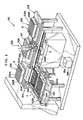
- An assay apparatus 210 or biosensor apparatus is for the surface plasmon resonance assay.
- the assay apparatus 210 includes a flow cell support 212, a flow cell moving unit 214, a reservoir support 216, a fluid dispenser 220 with a multiple pipette assembly, an optical assay unit 254, and a controller 260 as speed controller.
- the flow cell support 212 is a combination of various elements which are a pallet 212A, a belt 212B and the like.
- the belt 212B extends in the arrow direction Y, has the pallet 212A secured thereto, and turns about to move the pallet 212A in the direction Y.
- a tray or holder T is placed on the pallet 212A.
- An SPR sensor unit or sensor stick 240 for surface plasmon resonance (SPR) assay is contained in the tray or holder T.
- the sensor unit 240 has a chip for immobilizing the ligand D.
- a shifting mechanism 212D is disposed lower than the pallet 212A.
- a flow cell positioning panel 214C is disposed in a position where the sensor unit 240 can be shifted up by the shifting mechanism 212D. 3
- the sensor unit or sensor stick 240 includes a prism 242 as dielectric medium, a flow cell 244, a sealing mechanism 246, a double sided adhesive tape 248, and a flow cell lid 249 for preventing evaporation.
- the prism 242 is formed from transparent resin with high transmittance of light, and includes a prism portion 242A and retention portions 242B.
- the prism portion 242A is in a shape of polyhedron and extends long in one direction.
- the retention portions 242B are formed with ends of the prism portion 242A as molded portions.
- metal film or thin film 250 with a sensing surface is formed on the upper surface of the prism portion 242A, the upper surface being one of two horizontal surfaces but larger than a remaining one of those.
- Ligand D for analysis with the assay apparatus 210 is immobilized on the thin film 250.
- the prism 242 is an optical device, of which the prism portion 242A has first and second side surfaces not parallel with one another, receives a light beam through the first side surface, and causes exit of the light beam through the second side surface upon reflection on an interface between the prism portion 242A and the thin film 250.
- a linker film 250A as sensing surface is formed on the thin film 250.
- the linker film 250A is used to immobilize the ligand D on the thin film 250.
- the measuring region E1 has immobilization of a ligand D, and is a region for reaction between the ligand D and analyte A.
- the reference region E2 does not have immobilization of a ligand D, and is used for outputting a reference signal for comparison with a signal retrieved from the measuring region E1. Note that the reference region E2 is formed in the course of film production of the linker film 250A.
- An example of a process of the forming has steps of surface processing of the linker film 250A at first, and then deactivating the reaction groups in approximately a half of an entire area of the linker film 250A for binding with ligand D.
- a half of the linker film 250A becomes the measuring region E1.
- the other half of the linker film 250A becomes the reference region E2.
- alkyl thiol instead of carboxy methyl dextran in the reference region E2. This makes it possible to position the alkyl group on the surface.
- the alkyl group is not bindable in the amino coupling method, and thus can construct the reference region E2.
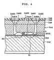
- Fig. 5 there is a flow channel 245 in which the linker film 250A extends.
- the ligand D is immobilized in an area of the linker film 250A different from the reference region E2. There is no ligand D immobilized in the reference region E2.
- Portions of the linker film 250A are subjected to application of light beams L2 and L1, the portions being included in the reference region E2 and the measuring region E1 upstream from the reference region E2.
- the reference region E2 is an area for correcting data obtained from the measuring region E1 with the ligand D immobilized thereon.
- engageable projections 242C and projections 242D are formed on lateral faces of the prism portion 242A.
- the engageable projections 242C are located on an upper edge, and engageable with the sealing mechanism 246.
- the projections 242D are located on a lower edge, and lie on an extension of a virtual surface vertical to the upper surface of the prism portion 242A.
- An engageable channel 242E is formed in a middle portion of the lower face of the prism 242 as viewed longitudinally.
- a width of the flow cell 244 in a long box shape is slightly smaller than a width of the prism 242.
- six flow cells 244 are arranged on the thin film 250 of the prism 242.
- a channel recess 244A is formed in a lower portion of the flow cell 244.
- An entrance orifice or first orifice 245A and an exit orifice or second orifice 245B are formed through an upper portion of the flow cell 244, and are connected with the channel recess 244A, so the flow channel 245 as a path is formed with the thin film 250.
- the six flow channels 245 are separately formed in the sensor unit or sensor stick 240.
- a projection 244B is formed in each of lateral walls of the flow cell 244, for being pressed in a recess (not shown) in the sealing mechanism 246, for keeping the joint sealed in contact with the sealing mechanism 246.
- a preferable example of material of the flow cell 244 is one that does not have non-specific adsorption to protein. This is because fluid containing protein flows in the flow channel 245, but must be prevented from sticking on the inside of the flow cell 244.
- a passage aperture 246D is formed in the upper panel 246A for the position of each of the first and second orifices 245A and 245B in the flow cell 244, and has a shape with a decreasing width toward the flow cell 244.
- Rod shaped bosses 246E are formed between the passage apertures 246D for positioning.
- the flow cell lid 249 is attached to the upper face of the sealing mechanism 246 by the double sided adhesive tape 248.
- Apertures 248D for access are formed in the double sided adhesive tape 248 and positioned at the passage apertures 246D for pipette insertion.
- Positioning holes 249E are formed in the double sided adhesive tape 248 and opposed to the bosses 246E.
- a cross shaped slit 249D is formed in the flow cell lid 249 and opposed to the passage aperture 246D.
- Holes 248E are formed in the flow cell lid 249 at the bosses 246E.
- the bosses 246E are inserted in the holes 248E and the positioning holes 249E, to attach the flow cell lid 249 on the upper face of the sealing mechanism 246, to oppose the cross shaped slit 249D of the flow cell lid 249 to the first and second orifices 245A and 245B of the flow cell 244.
- the portion of the cross shaped slit 249D closes the first orifice 245A, to prevent evaporation of fluid in the flow channel 245.
- elements of the flow cell moving unit 214 of the assay apparatus 210 include an upper rail 214A, a lower rail 214B and the flow cell positioning panel 214C.
- the upper and lower rails 214A and 214B extend horizontally in the direction of the arrow X that is crosswise to the arrow Y, and are disposed higher than the flow cell support 212 and the optical assay unit 254.
- the flow cell positioning panel 214C is secured to the upper rail 214A.
- the flow cell positioning panel 214C keeps the retention portions 242B at ends of the sensor unit or sensor stick 240, and is movable along the upper rail 214A.
- the engageable channel 242E of the sensor unit 240 on the flow cell positioning panel 214C is engaged with the lower rail 214B.
- a photo detection region 256 is disposed on the optical assay unit 254, and is provided with the sensor unit 240 when the flow cell positioning panel 214C moves in the direction of the arrow X.
- a fastener 258 is disposed in the photo detection region 256 and fastens the sensor unit 240 during the assay. The fastener 258 is kept movable in the direction of the arrow Z by a driving mechanism (not shown), and retains the sensor unit 240 downwards in the photo detection region 256 with pressure.
- An analyte reservoir 217 or multi well analyte plate, a buffer reservoir 218 or multi well buffer plate, and a waste fluid reservoir 219 or multi well waste fluid receptacle are placed on the reservoir support 216.
- the analyte reservoir 217 has regions distributed in a matrix form, and stores analyte fluids of various types.
- Wells 218A-218E are included in the buffer reservoir 218, and store buffers of various types.
- An opening K is defined in each of the wells 218A-218E for insertion of the pipette tip CP.
- Wells 219A-219E are included in the waste fluid reservoir 219 as receptacles of waste fluid.
- an opening K is defined in each of the wells 219A-219E for insertion of the pipette tip CP.
- the fluid dispenser 220 includes a pipette head 224 in a multiple pipette assembly, and a fluid transfer mechanism 226 for dispensation and aspiration.
- the pipette head 224 is movable in the direction Y along transport rails (not shown).
- a driving mechanism (not shown) in the pipette head 224 moves the unit of the pipette head 224 in the vertical direction indicated with the arrow Z.
- the pipette head 224 includes pipette devices 224A and 224B with pipette nozzles.
- a pipette tip CP is fitted on each of the pipette devices 224A and 224B, so that a length of each of the pipette unit is changeable in the direction Z.
- a great number of the pipette tips CP are stored in a pipette tip storage, and are exchangeable if required.
- the fluid transfer mechanism 226 includes a first pump or dispensing pump 227 and a second pump or aspirating pump 228.
- the dispensing pump 227 is structurally a syringe pump, and includes a cylinder 227A, a piston 227B, and a first pump motor 227C for driving the piston 227B.
- the aspirating pump 228 is structurally a syringe pump, and includes a cylinder 228A, a piston 228B, and a second pump motor 228C for driving the piston 228B.
- the pump motors 227C and 228C are connected with respectively pump drivers 260D and 260E provided in the controller 260.
- the optical assay unit 254 includes a light source 254A, a first optical system 254B, a second optical system 254C, a photo detector 254D and a signal processor 254E.
- a light L or light beam of a diffused state is emitted by the light source 254A.
- the first optical system 254B receives the light L and converts this into two light beams L1 and L2, which become incident on the regions of the prism 242 on the photo detection region 256.
- the light or light beams L1 and L2 are incident on the interface between the thin film 250 and the prism 242 with numerous components of incident angles, and also are incident at angles equal to or more than an angle enough for total reflection.
- the light L1 and L2 is reflected by the interface between the prism 242 and the thin film 250 in the manner of total reflection. There are plural angles as angular components of reflections in the totally reflected light L1 and L2.
- the light L1 and L2 is passed through the second optical system 254C, received by the photo detector 254D and converted photoelectrically, so that a detection signal is sent to the signal processor 254E.
- the signal processor 254E processes information according to the detection signal, and determines data of angles of attenuated total reflection of the measuring and reference regions E1 and E2.
- the angle data are output to the controller 260.
- the controller 260 controls the entirety of the assay apparatus 210.
- the controller 260 is connected with the light source 254A,'the signal processor 254E and a driving system (not shown) for the assay apparatus 210.
- the controller 260 includes not only the pump drivers 260D and 260E but a CPU 260A, ROM 260B, RAM 260C, a memory 260F and interfaces 260H, 260I and 260J.
- a bus 260G connects those elements with one another.
- the pump driver 260D is connected with the first pump motor 227C.
- the pump driver 260E is connected with the second pump motor 228C.
- a display panel 262 is connected by the interface 260H with the controller 260 for displaying information of various kinds.
- An input panel 264 is connected by the interface 260H with the controller 260 for inputting various signals for command and information.
- the signal processor 254E and the light source 254A are connected by the interface 260I.
- the pipette head 224 is connected by the interface 260J.
- the ROM 260B stores programs for control of the pipette head 224, and the dispensing and aspirating pumps 227 and 228.
- the memory 260F stores a data table T of data of a relationship between the finite difference S and the corrected speeds ⁇ and ⁇ .
- the finite difference S is defined between dispensing and aspirating flow rates of the dispensing and aspirating pumps 227 and 228 per unit time.
- the corrected speeds ⁇ and ⁇ are levels of speed of the dispensing and aspirating pumps 227 and 228 for canceling the finite difference S.
- the finite difference S is derived from an error in an inner diameter of the cylinder of the syringe pump. Note that information of the corrected speeds ⁇ and ⁇ may not be speeds itself, but can be information represented by numbers of pulses of the stepping motor, or information of rates of increase or decrease of the speed.
- one of the corrected speeds ⁇ and ⁇ may be omitted, and only a remaining one of those for either one of the dispensing and aspirating pumps 227 and 228 may be used.
- the finite difference S in the assay apparatus 210 of the embodiment is previously determined experimentally.
- plural values are prepared and selectively used. Symbols S1, ⁇ 1 and ⁇ 1 are used herein.
- information for the corrected speeds ⁇ and ⁇ of the pumps may be in any suitable form, for example pressure exerted by pumps to fluid, energy for driving the pumps with the motors, or other quantitative values.
- a tray is set on the pallet 212A of the assay apparatus 210, with the sensor unit or sensor stick 240 where the ligand D is immobilized and the flow channel 245 is filled with the fluid C for preservation.
- Analyte fluid is stored in the analyte reservoir 217.
- the shifting mechanism 212D shifts up the sensor unit or sensor stick 240 to the position of the flow cell positioning panel 214C, for the flow cell positioning panel 214C to keep the sensor unit 240. Then the flow cell positioning panel 214C with the sensor unit 240 shifts along the lower rail 214B, to transport the sensor unit 240 to the photo detection region 256.
- the sensor unit 240 in the photo detection region 256 is set suitably in assay position, and kept immovable by the fastener 258 with downward pressure.
- a command signal for starting the assay is input by the input panel 264.
- the assay of Fig. 10 is started by the controller 260.
- the light source 254A is provided with a command signal for emission of the light L.
- the light source 254A responsively emits the light L.
- the first optical system 254B converts the light L into two light beams L1 and L2, which become incident on the measuring and reference regions E1 and E2.
- the controller 260 sends a command signal to the photo detector 254D and the signal processor 254E.
- the light L1 and L2 passed through the second optical system 254C after total reflection on the measuring and reference regions E1 and E2, is received by the photo detector 254D.
- the light L1 and L2 is photoelectrically detected in each of the measuring and reference regions E1 and E2, to send detection signals to the signal processor 254E.
- the signal processor 254E processes the detection signals, and creates angle data of the attenuated total reflection. The angle data is sent to the controller 260.
- the controller 260 determines whether time of a preset length has elapsed or not.
- the angle data of the attenuated total reflection is written to the memory 260F.
- angle data according to the detection signal from the measuring region E1 is corrected by considering angle data according to the detection signal from the reference region E2.
- Data of a binding state is created, the binding state being of the ligand D with the analyte A in the analyte fluid YA.
- the data of the binding state is output to the display panel 262.
- the data of the binding state per unit time is written to the memory 260F, and can be displayed on the display panel 262.
- a form of displaying the data of the binding state is a graph form. Note that the operation of the assay is continued until reception of the end signal of measuring in the assay.
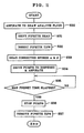
- the controller 260 When a command signal for starting delivery of analyte is input by the input panel 264, then the controller 260 operates for the process of analyte delivery as illustrated in Fig. 11 .
- the analyte fluid YA is delivered by aspiration through the pipette tip CPA.
- the pipette head 224 is shifted and set higher than the analyte reservoir 217 storing the analyte fluid YA.
- the pipette device 224A is moved down to insert only an end of the pipette tip CPA secured to the pipette device 224A, for insertion in a well storing the analyte fluid YA.
- the first pump motor 227C drives the piston 227B for decompression of the cylinder 227A with negative pressure.
- the analyte fluid YA is aspirated and drawn into the pipette tip CPA.
- the pipette head 224 is moved to the sensor unit or sensor stick 240.
- the pipette tip CPA is inserted in the first orifice 245A.
- the pipette tip CPB is inserted in the second orifice 245B.
- the corrected speeds ⁇ 1 and ⁇ 1 are read from the memory 260F.
- the controller 260 outputs command signals to the pump drivers 260D and 260E to drive the pump motors 227C and 228C at the corrected speeds ⁇ 1 and ⁇ 1.
- the analyte fluid YA is dispensed by the pipette tip CPA to introduce to the flow channel 245.
- the buffer liquid in the flow channel 245 is aspirated and removed by the pipette tip CPB.
- step S35 the apparatus waits to stand until lapse of predetermined time for delivery of analyte fluid YA of a predetermined amount. Upon the lapse of predetermined time, the dispensing and aspirating pumps 227 and 228 are stopped in the step S36.
- step S37 the pipette tips CPA and CPB are removed from the first and second orifices 245A and 245B.
- step S38 the buffer liquid in the pipette tip CPB is drained to the waste fluid reservoir 219. Thus, the operation of delivery of the analyte is completed.
- the assay is completed when a completion command signal is received.
- the introduction of the analyte fluid YA to the flow channel 245 is according to driving of the dispensing and aspirating pumps 227 and 228 at the corrected speeds ⁇ 1 and ⁇ 1. Changes in the pressure of the fluid delivery can be suppressed because a difference can be canceled between the dispensing flow rate to the flow channel 245 and the aspirating flow rate from the flow channel 245 per unit time. Failure in the introduction of fluid can be prevented, to make higher the reliability of the assay apparatus 210.
- speed of the dispensing or aspirating pump 227 or 228 is corrected in relation to the analyte fluid YA.
- speed of the dispensing or aspirating pump 227 or 228 is corrected in relation to the analyte fluid YA.
- FIG. 12 another preferred embodiment of a multichannel type is illustrated.
- a multichannel pipette head 274 in multiple pipette assemblies is provided with 12 pipette devices 274A-274L in six couples. Fluids can be sent to a plurality of the flow channels 245 at one time.
- the pipette devices 274A, 274C, 274E, 274G, 274I and 274K are on the side of dispensation at one time. Each of those is inserted in the first orifice 245A and operated by driving of the dispensing pump 227 with the pump driver 260D.
- pipette devices 274B, 274D, 274F, 274H, 274J and 274L are on the side of aspiration at one time. Each of those is inserted in the second orifice 245B and operated by driving of the aspirating pump 228 with the pump driver 260E.
- the corrected speed for canceling the finite difference S between the dispensing and aspirating flow rates is referred to.
- Fig. 13 only the corrected speed ⁇ of the aspirating pump 228 is stored.
- the aspirating pump 228 is driven at the corrected speed ⁇ by use of an associated one pump driver 260E.
- the assay apparatus for a counterflow from the pipette tip CPB toward the pipette tip CPA if it is desired.
- the first pump 227 is driven for aspiration.
- the second pump 228 is driven for dispensation. Corrected speeds of those are the corrected speeds ⁇ and ⁇ .
- a negative value of the correction table T is used for corrected speeds. Consequently, errors can be corrected in the time of the counterflow, so as to suppress changes an inner pressure.
- the assay apparatus 210 is according to surface plasmon resonance (SPR) assay.
- the assay apparatus 210 of the invention can be any suitable apparatus of systems of (bio) chemical assay.
- Measurement in which analyte is removed according to the invention may be any of suitable systems, for example, quartz crystal microbalance (QCM) measurement with quartz of oscillation, and measurement of functioning surfaces of various particles including colloid particles of gold, and ultramicro particles.
- QCM quartz crystal microbalance
- an assay sensor unit according to the invention can be other sensor in utilizing attenuated total reflection, for example, a leaky mode sensor.
- a pipette device group having plural pipette devices may be constituted by a single multiple pipette assembly, or a plurality of multiple pipette assemblies, or a plurality of single pipette devices.
- a multiple pipette assembly is generally combined with one pipette head, and may have any number of single pipette devices, for example, two, four, eight or so.
Landscapes
- Chemical & Material Sciences (AREA)
- Health & Medical Sciences (AREA)
- Chemical Kinetics & Catalysis (AREA)
- Analytical Chemistry (AREA)
- General Health & Medical Sciences (AREA)
- Biochemistry (AREA)
- Life Sciences & Earth Sciences (AREA)
- Physics & Mathematics (AREA)
- General Physics & Mathematics (AREA)
- Immunology (AREA)
- Pathology (AREA)
- Clinical Laboratory Science (AREA)
- Hematology (AREA)
- Investigating Or Analysing Materials By Optical Means (AREA)
- Automatic Analysis And Handling Materials Therefor (AREA)
Claims (5)
- Fluidspender zum Spenden und Zuführen einer Probe (A, D) zu einer Sensorfläche (250A) in einer Sensoreinheit (240), wobei die Sensoreinheit einen Strömungskanal (245) mit einer ersten und einer zweiten Öffnung (245A, 245B) enthält, und die Sensorfläche im Inneren des Strömungskanals positioniert ist, um eine Reaktion der Probe nachzuweisen, wobei der Fluidspender umfasst:eine Pipetteneinrichtungsgruppe (224, 274) mit einer ersten und einer zweiten Pipetteneinrichtung (224A, 224B, 274A-274L), die an der ersten bzw. der zweiten Öffnung anzusetzen sind;eine Spenderpumpe (227), um die erste Pipetteneinrichtung (224A, 274A, 274C) zu veranlassen, die Probe zu spenden; undeine Ansaugpumpe (228) zum Veranlassen der zweiten Pipetteneinrichtung (224B, 274B, 274D) zum Ansaugen der Probe;gekennzeichnet durcheine Geschwindigkeitssteuerung (260) zum Steuern der Geschwindigkeiten (α, β) der Spende- und Ansaugpumpen, um eine endliche Differenz (S) zwischen dem Spendeströmungsdurchsatz und einem Ansaugströmungsdurchsatz aufzuheben, wobei der Spendeströmungsdurchsatz zu der ersten Pipetteneinrichtung und der Spendepumpe pro Zeiteinheit gehört, und der Ansaugströmungsdurchsatz zu der zweiten Pipetteneinrichtung und der Ansaugpumpe pro Zeiteinheit gehört.
- Fluidspender nach Anspruch 1, bei dem die Geschwindigkeitssteuerung enthält:einen Speicher zum Speichern von Information einer korrigierten Geschwindigkeit von mindestens einer der Spende- und Ansaugpumpen, um eine endliche Differenz zwischen dem Spendeströmungsdurchsatz und dem Ansaugströmungsdurchsatz aufzuheben; undeinen Pumpentreiber zum Treiben der Spende- und Ansaugpumpen entsprechend der korrigierten Geschwindigkeit.
- Fluidspender nach Anspruch 1, bei dem die Pipetteneinrichtungsgruppe durch mehrere Pipetteneinrichtungsgruppen gebildet wird,
weiterhin umfassend:einen Speicher zum Speichern von Information einer korrigierten Geschwindigkeit der Ansaugpumpe für jede der mehreren Pipetteneinrichtungsgruppen, um eine endliche Differenz zwischen dem Spendeströmungsdurchsatz und dem Ansaugströmungsdurchsatz aufzuheben; undeinen Pumpentreiber zum Treiben der Ansaugpumpe gemäß der korrigierten Geschwindigkeit. - Prüfvorrichtung für eine Prüfung unter Nutzung gedämpfter Totalreflexion, in der die Sensoreinheit (240) nach Anspruch 1 mit einer Dünnschicht (250) verwendet wird, wobei die Prüfvorrichtung aufweist:einen Fluidspender nach Anspruch 1,eine Lichtquelle (254A) zum Emittieren von Beleuchtungslicht in Richtung der Dünnschicht; undeinen Photodetektor (254D) zum Nachweisen des von der Dünnschicht reflektierten Beleuchtungslichts.
- Fluidspendeverfahren zum Spenden einer Probe (A, D) auf eine Sensorfläche (250A) in einer Sensoreinheit (240), wobei die Sensoreinheit einen Strömungskanal (245) mit einer ersten und einer zweiten Öffnung (245A, 245B) enthält und die Sensorfläche innerhalb des Strömungskanals positioniert ist, um eine Reaktion der Probe nachzuweisen, wobei das Fluidspendeverfahren folgenden Schritt aufweist:Einstellen einer ersten und einer zweiten Pipetteneinrichtung (224A, 224B, 274A-274L) an der ersten bzw. der zweiten Öffnung, wobei die erste und die zweite Pipetteneinrichtung eine Pipetteneinrichtungsgruppe (224, 274) bilden;gekennzeichnet durch den Schritt desSteuerns der Geschwindigkeit (α, β) von Spende- und Ansaugpumpen (227, 228) zum Aufheben einer endlichen Differenz (S) zwischen einem Spendeströmungsdurchsatz und einem Ansaugströmungsdurchsatz, wobei der Spendeströmungsdurchsatz zu der ersten Pipetteneinrichtung (224A, 274A, 274C) und der Spendepumpe pro Zeiteinheit gehört, und der Ansaugströmungsdurchsatz zu der zweiten Pipetteneinrichtung (224B, 274B, 274D) und der Ansaugpumpe pro Zeiteinheit gehört.
Priority Applications (1)
| Application Number | Priority Date | Filing Date | Title |
|---|---|---|---|
| EP06023740A EP1767271B1 (de) | 2005-04-13 | 2006-04-12 | Untersuchungssystem mit einer Abgabevorrichtung für Fluide und einer Sensoreinheit |
Applications Claiming Priority (3)
| Application Number | Priority Date | Filing Date | Title |
|---|---|---|---|
| JP2005116057 | 2005-04-13 | ||
| JP2005284529A JP2007093444A (ja) | 2005-09-29 | 2005-09-29 | 送液装置、バイオセンサー、及び、送液方法 |
| JP2006088198A JP4740010B2 (ja) | 2005-04-13 | 2006-03-28 | 送液装置及びその送液方法並びに全反射減衰を利用した測定装置 |
Related Child Applications (2)
| Application Number | Title | Priority Date | Filing Date |
|---|---|---|---|
| EP06023740A Division EP1767271B1 (de) | 2005-04-13 | 2006-04-12 | Untersuchungssystem mit einer Abgabevorrichtung für Fluide und einer Sensoreinheit |
| EP06023740.1 Division-Into | 2006-11-15 |
Publications (2)
| Publication Number | Publication Date |
|---|---|
| EP1712285A1 EP1712285A1 (de) | 2006-10-18 |
| EP1712285B1 true EP1712285B1 (de) | 2011-06-15 |
Family
ID=36648801
Family Applications (2)
| Application Number | Title | Priority Date | Filing Date |
|---|---|---|---|
| EP06007757A Not-in-force EP1712285B1 (de) | 2005-04-13 | 2006-04-12 | Abgabevorrichtung und -methode für Fluide und Untersuchungsvorrichtung zur Untersuchung mittels abgeschwächter Totalreflektion |
| EP06023740A Not-in-force EP1767271B1 (de) | 2005-04-13 | 2006-04-12 | Untersuchungssystem mit einer Abgabevorrichtung für Fluide und einer Sensoreinheit |
Family Applications After (1)
| Application Number | Title | Priority Date | Filing Date |
|---|---|---|---|
| EP06023740A Not-in-force EP1767271B1 (de) | 2005-04-13 | 2006-04-12 | Untersuchungssystem mit einer Abgabevorrichtung für Fluide und einer Sensoreinheit |
Country Status (1)
| Country | Link |
|---|---|
| EP (2) | EP1712285B1 (de) |
Cited By (4)
| Publication number | Priority date | Publication date | Assignee | Title |
|---|---|---|---|---|
| US8476015B2 (en) | 2009-12-10 | 2013-07-02 | Roche Molecular Systems, Inc. | Method for separating and detecting an analyte |
| US8772036B2 (en) | 2010-06-29 | 2014-07-08 | Roche Molecular Systems, Inc. | Automated method for sample distribution and isolation of an analyte with a solid support |
| WO2015051654A1 (zh) * | 2013-10-10 | 2015-04-16 | 广州安必平自动化检测设备有限公司 | 一种移液装置及移液方法 |
| CN107744839A (zh) * | 2017-09-21 | 2018-03-02 | 微思行(北京)科技有限公司 | 一种管架 |
Families Citing this family (12)
| Publication number | Priority date | Publication date | Assignee | Title |
|---|---|---|---|---|
| JP2008233027A (ja) * | 2007-03-23 | 2008-10-02 | Fujifilm Corp | 液体タンク、及び、液循環装置 |
| FI20085815A (fi) | 2008-09-02 | 2010-03-03 | Wallac Oy | Laitteisto, järjestelmä ja menetelmä nestemäisten näytteiden suodattamiseksi |
| US8900878B2 (en) | 2008-11-28 | 2014-12-02 | Roche Molecular Systems Inc. | Pipetting device, modular pipetting unit, pipetting system and method for pipetting of fluid samples |
| EP2221603A1 (de) * | 2009-02-18 | 2010-08-25 | Koninklijke Philips Electronics N.V. | Messvorrichtung zum Erfassen einer Zielsubstanz |
| CN101596469B (zh) * | 2009-07-03 | 2011-12-28 | 烟台艾德康生物科技有限公司 | 多通道加样设备 |
| JP5585138B2 (ja) * | 2010-03-17 | 2014-09-10 | オムロン株式会社 | 流路チップ及び治具 |
| CN102539806B (zh) * | 2012-02-16 | 2013-05-08 | 哈尔滨工业大学(威海) | 一种多通道液体加样等量分距装置 |
| CN108027379B (zh) | 2015-06-26 | 2021-07-23 | 雅培实验室 | 用于诊断分析设备的反应容器交换装置 |
| EP3593146A4 (de) * | 2017-04-20 | 2020-07-29 | Biofluidica, Inc. | Fluiddichtes durchflusssystem zur isolierung von biomarkern aus einer flüssigen probe |
| CN110551610B (zh) * | 2019-09-29 | 2023-11-21 | 深圳赛动生物自动化有限公司 | 泵液装置及其工作方法 |
| EP4164795A4 (de) | 2020-06-12 | 2024-01-24 | Biofluidica Inc | Thermoplastische mikrofluidische vorrichtung mit zwei tiefen und zugehörige systeme und verfahren |
| GB202016426D0 (en) * | 2020-10-16 | 2020-12-02 | Clinspec Diagnostics Ltd | Continuous infrared spectroscopy system and method |
Family Cites Families (8)
| Publication number | Priority date | Publication date | Assignee | Title |
|---|---|---|---|---|
| US5055263A (en) * | 1988-01-14 | 1991-10-08 | Cyberlab, Inc. | Automated pipetting system |
| SE462408B (sv) | 1988-11-10 | 1990-06-18 | Pharmacia Ab | Optiskt biosensorsystem utnyttjande ytplasmonresonans foer detektering av en specific biomolekyl, saett att kalibrera sensoranordningen samt saett att korrigera foer baslinjedrift i systemet |
| US5537880A (en) * | 1995-06-07 | 1996-07-23 | Abbott Laboratories | Automatic pipetting apparatus with leak detection and method of detecting a leak |
| US5750881A (en) * | 1995-07-13 | 1998-05-12 | Chiron Diagnostics Corporation | Method and apparatus for aspirating and dispensing sample fluids |
| US6370942B1 (en) | 2000-05-15 | 2002-04-16 | Dade Behring Inc. | Method for verifying the integrity of a fluid transfer |
| US6948389B2 (en) | 2002-03-18 | 2005-09-27 | Distek, Inc. | Dissolution test sampling |
| WO2004034436A2 (en) * | 2002-10-09 | 2004-04-22 | Cellectricon Ab | Method for interfacing macroscale components to microscale devices |
| DE60232689D1 (de) * | 2002-12-25 | 2009-07-30 | Bio Rad Laboratories | Oberflächenplasmonenresonanzsensor |
-
2006
- 2006-04-12 EP EP06007757A patent/EP1712285B1/de not_active Not-in-force
- 2006-04-12 EP EP06023740A patent/EP1767271B1/de not_active Not-in-force
Cited By (7)
| Publication number | Priority date | Publication date | Assignee | Title |
|---|---|---|---|---|
| US8476015B2 (en) | 2009-12-10 | 2013-07-02 | Roche Molecular Systems, Inc. | Method for separating and detecting an analyte |
| US9315801B2 (en) | 2009-12-10 | 2016-04-19 | Roche Molecular Systems, Inc. | Method for separating and detecting an analyte |
| US8772036B2 (en) | 2010-06-29 | 2014-07-08 | Roche Molecular Systems, Inc. | Automated method for sample distribution and isolation of an analyte with a solid support |
| US9383379B2 (en) | 2010-06-29 | 2016-07-05 | Roche Molecular Systems, Inc. | Sample distribution in a method for isolating analytes in fluid samples in an automated system |
| US9383378B2 (en) | 2010-06-29 | 2016-07-05 | Roche Molecular Systems, Inc. | Sample distribution in an analytical system for processing an analyte |
| WO2015051654A1 (zh) * | 2013-10-10 | 2015-04-16 | 广州安必平自动化检测设备有限公司 | 一种移液装置及移液方法 |
| CN107744839A (zh) * | 2017-09-21 | 2018-03-02 | 微思行(北京)科技有限公司 | 一种管架 |
Also Published As
| Publication number | Publication date |
|---|---|
| EP1767271A1 (de) | 2007-03-28 |
| EP1712285A1 (de) | 2006-10-18 |
| EP1767271B1 (de) | 2012-12-05 |
Similar Documents
| Publication | Publication Date | Title |
|---|---|---|
| EP1712285B1 (de) | Abgabevorrichtung und -methode für Fluide und Untersuchungsvorrichtung zur Untersuchung mittels abgeschwächter Totalreflektion | |
| US20060257290A1 (en) | Fluid dispenser, fluid dispensing method and assay apparatus for assay in utilizing attenuated total reflection | |
| US7858041B2 (en) | Fluid dispenser for fluid in assay | |
| US20030080143A1 (en) | System and method for dispensing liquids | |
| US4265855A (en) | System for performing immunochemical and other analyses involving phase separation | |
| US6104484A (en) | Measuring chip for optical analyzer | |
| CA2391758C (en) | Apparatus for liquid sample handling | |
| JPH05240868A (ja) | 標本の自動分析装置 | |
| US7611905B2 (en) | Apparatus and method of assay in utilizing attenuated total reflection | |
| JP7223767B2 (ja) | 自動体積測定装置 | |
| US20090114255A1 (en) | Cleaning apparatus and automatic analyzer | |
| EP1637869B1 (de) | Analyse-Verfahren unter Verwendung von abgeschwächter Totalreflektion | |
| US7545501B2 (en) | Sensor unit for assay and prism | |
| EP1643237A1 (de) | Vorrichtung und Verfahren zur quantitativen Messung von immobilisierten Proben | |
| US20020155516A1 (en) | Method for minimizing optical interference during antibiotic susceptibility readings in a microbiological analyzer | |
| JPWO2007132632A1 (ja) | 洗浄装置および自動分析装置 | |
| WO2009148013A1 (ja) | 検体分注装置のプローブ洗浄方法、検体分注装置及び自動分析装置 | |
| WO2021215060A1 (ja) | 自動分析装置、分注装置および分注制御方法 | |
| US20060252158A1 (en) | Sample recovery method and device | |
| JPH0972923A (ja) | 分注装置及び方法 | |
| JP2001324510A (ja) | 吐出容量可変液体分注装置 | |
| GB2368640A (en) | Liquid sample handling or transferring device | |
| AU2002338339A1 (en) | System and method for dispensing liquids |
Legal Events
| Date | Code | Title | Description |
|---|---|---|---|
| PUAI | Public reference made under article 153(3) epc to a published international application that has entered the european phase |
Free format text: ORIGINAL CODE: 0009012 |
|
| AK | Designated contracting states |
Kind code of ref document: A1 Designated state(s): AT BE BG CH CY CZ DE DK EE ES FI FR GB GR HU IE IS IT LI LT LU LV MC NL PL PT RO SE SI SK TR |
|
| AX | Request for extension of the european patent |
Extension state: AL BA HR MK YU |
|
| RAP1 | Party data changed (applicant data changed or rights of an application transferred) |
Owner name: FUJIFILM CORPORATION |
|
| 17P | Request for examination filed |
Effective date: 20070323 |
|
| AKX | Designation fees paid |
Designated state(s): CH DE FR GB LI SE |
|
| 17Q | First examination report despatched |
Effective date: 20100505 |
|
| GRAP | Despatch of communication of intention to grant a patent |
Free format text: ORIGINAL CODE: EPIDOSNIGR1 |
|
| GRAS | Grant fee paid |
Free format text: ORIGINAL CODE: EPIDOSNIGR3 |
|
| GRAA | (expected) grant |
Free format text: ORIGINAL CODE: 0009210 |
|
| AK | Designated contracting states |
Kind code of ref document: B1 Designated state(s): CH DE FR GB LI SE |
|
| REG | Reference to a national code |
Ref country code: GB Ref legal event code: FG4D Ref country code: CH Ref legal event code: EP |
|
| REG | Reference to a national code |
Ref country code: DE Ref legal event code: R096 Ref document number: 602006022472 Country of ref document: DE Effective date: 20110728 |
|
| PG25 | Lapsed in a contracting state [announced via postgrant information from national office to epo] |
Ref country code: SE Free format text: LAPSE BECAUSE OF FAILURE TO SUBMIT A TRANSLATION OF THE DESCRIPTION OR TO PAY THE FEE WITHIN THE PRESCRIBED TIME-LIMIT Effective date: 20110615 |
|
| PLBE | No opposition filed within time limit |
Free format text: ORIGINAL CODE: 0009261 |
|
| STAA | Information on the status of an ep patent application or granted ep patent |
Free format text: STATUS: NO OPPOSITION FILED WITHIN TIME LIMIT |
|
| 26N | No opposition filed |
Effective date: 20120316 |
|
| REG | Reference to a national code |
Ref country code: DE Ref legal event code: R097 Ref document number: 602006022472 Country of ref document: DE Effective date: 20120316 |
|
| REG | Reference to a national code |
Ref country code: CH Ref legal event code: PL |
|
| PG25 | Lapsed in a contracting state [announced via postgrant information from national office to epo] |
Ref country code: CH Free format text: LAPSE BECAUSE OF NON-PAYMENT OF DUE FEES Effective date: 20120430 Ref country code: LI Free format text: LAPSE BECAUSE OF NON-PAYMENT OF DUE FEES Effective date: 20120430 |
|
| PGFP | Annual fee paid to national office [announced via postgrant information from national office to epo] |
Ref country code: GB Payment date: 20140409 Year of fee payment: 9 |
|
| PGFP | Annual fee paid to national office [announced via postgrant information from national office to epo] |
Ref country code: DE Payment date: 20140430 Year of fee payment: 9 Ref country code: FR Payment date: 20140409 Year of fee payment: 9 |
|
| REG | Reference to a national code |
Ref country code: DE Ref legal event code: R119 Ref document number: 602006022472 Country of ref document: DE |
|
| GBPC | Gb: european patent ceased through non-payment of renewal fee |
Effective date: 20150412 |
|
| PG25 | Lapsed in a contracting state [announced via postgrant information from national office to epo] |
Ref country code: GB Free format text: LAPSE BECAUSE OF NON-PAYMENT OF DUE FEES Effective date: 20150412 Ref country code: DE Free format text: LAPSE BECAUSE OF NON-PAYMENT OF DUE FEES Effective date: 20151103 |
|
| REG | Reference to a national code |
Ref country code: FR Ref legal event code: ST Effective date: 20151231 |
|
| PG25 | Lapsed in a contracting state [announced via postgrant information from national office to epo] |
Ref country code: FR Free format text: LAPSE BECAUSE OF NON-PAYMENT OF DUE FEES Effective date: 20150430 |