EP1712279A2 - Exhaust gas catalytic converter - Google Patents
Exhaust gas catalytic converter Download PDFInfo
- Publication number
- EP1712279A2 EP1712279A2 EP06006448A EP06006448A EP1712279A2 EP 1712279 A2 EP1712279 A2 EP 1712279A2 EP 06006448 A EP06006448 A EP 06006448A EP 06006448 A EP06006448 A EP 06006448A EP 1712279 A2 EP1712279 A2 EP 1712279A2
- Authority
- EP
- European Patent Office
- Prior art keywords
- oxygen storage
- catalyst
- storage component
- exhaust gas
- upstream
- Prior art date
- Legal status (The legal status is an assumption and is not a legal conclusion. Google has not performed a legal analysis and makes no representation as to the accuracy of the status listed.)
- Granted
Links
Images


Classifications
-
- B—PERFORMING OPERATIONS; TRANSPORTING
- B01—PHYSICAL OR CHEMICAL PROCESSES OR APPARATUS IN GENERAL
- B01D—SEPARATION
- B01D53/00—Separation of gases or vapours; Recovering vapours of volatile solvents from gases; Chemical or biological purification of waste gases, e.g. engine exhaust gases, smoke, fumes, flue gases, aerosols
- B01D53/34—Chemical or biological purification of waste gases
- B01D53/92—Chemical or biological purification of waste gases of engine exhaust gases
- B01D53/94—Chemical or biological purification of waste gases of engine exhaust gases by catalytic processes
- B01D53/9445—Simultaneously removing carbon monoxide, hydrocarbons or nitrogen oxides making use of three-way catalysts [TWC] or four-way-catalysts [FWC]
- B01D53/9454—Simultaneously removing carbon monoxide, hydrocarbons or nitrogen oxides making use of three-way catalysts [TWC] or four-way-catalysts [FWC] characterised by a specific device
-
- B—PERFORMING OPERATIONS; TRANSPORTING
- B01—PHYSICAL OR CHEMICAL PROCESSES OR APPARATUS IN GENERAL
- B01D—SEPARATION
- B01D53/00—Separation of gases or vapours; Recovering vapours of volatile solvents from gases; Chemical or biological purification of waste gases, e.g. engine exhaust gases, smoke, fumes, flue gases, aerosols
- B01D53/34—Chemical or biological purification of waste gases
- B01D53/92—Chemical or biological purification of waste gases of engine exhaust gases
- B01D53/94—Chemical or biological purification of waste gases of engine exhaust gases by catalytic processes
- B01D53/9445—Simultaneously removing carbon monoxide, hydrocarbons or nitrogen oxides making use of three-way catalysts [TWC] or four-way-catalysts [FWC]
- B01D53/945—Simultaneously removing carbon monoxide, hydrocarbons or nitrogen oxides making use of three-way catalysts [TWC] or four-way-catalysts [FWC] characterised by a specific catalyst
-
- B—PERFORMING OPERATIONS; TRANSPORTING
- B01—PHYSICAL OR CHEMICAL PROCESSES OR APPARATUS IN GENERAL
- B01J—CHEMICAL OR PHYSICAL PROCESSES, e.g. CATALYSIS OR COLLOID CHEMISTRY; THEIR RELEVANT APPARATUS
- B01J23/00—Catalysts comprising metals or metal oxides or hydroxides, not provided for in group B01J21/00
- B01J23/002—Mixed oxides other than spinels, e.g. perovskite
-
- B—PERFORMING OPERATIONS; TRANSPORTING
- B01—PHYSICAL OR CHEMICAL PROCESSES OR APPARATUS IN GENERAL
- B01J—CHEMICAL OR PHYSICAL PROCESSES, e.g. CATALYSIS OR COLLOID CHEMISTRY; THEIR RELEVANT APPARATUS
- B01J23/00—Catalysts comprising metals or metal oxides or hydroxides, not provided for in group B01J21/00
- B01J23/38—Catalysts comprising metals or metal oxides or hydroxides, not provided for in group B01J21/00 of noble metals
- B01J23/54—Catalysts comprising metals or metal oxides or hydroxides, not provided for in group B01J21/00 of noble metals combined with metals, oxides or hydroxides provided for in groups B01J23/02 - B01J23/36
- B01J23/56—Platinum group metals
- B01J23/63—Platinum group metals with rare earths or actinides
-
- B—PERFORMING OPERATIONS; TRANSPORTING
- B01—PHYSICAL OR CHEMICAL PROCESSES OR APPARATUS IN GENERAL
- B01J—CHEMICAL OR PHYSICAL PROCESSES, e.g. CATALYSIS OR COLLOID CHEMISTRY; THEIR RELEVANT APPARATUS
- B01J35/00—Catalysts, in general, characterised by their form or physical properties
- B01J35/19—Catalysts containing parts with different compositions
-
- B—PERFORMING OPERATIONS; TRANSPORTING
- B01—PHYSICAL OR CHEMICAL PROCESSES OR APPARATUS IN GENERAL
- B01J—CHEMICAL OR PHYSICAL PROCESSES, e.g. CATALYSIS OR COLLOID CHEMISTRY; THEIR RELEVANT APPARATUS
- B01J37/00—Processes, in general, for preparing catalysts; Processes, in general, for activation of catalysts
- B01J37/02—Impregnation, coating or precipitation
- B01J37/024—Multiple impregnation or coating
- B01J37/0244—Coatings comprising several layers
-
- B—PERFORMING OPERATIONS; TRANSPORTING
- B01—PHYSICAL OR CHEMICAL PROCESSES OR APPARATUS IN GENERAL
- B01J—CHEMICAL OR PHYSICAL PROCESSES, e.g. CATALYSIS OR COLLOID CHEMISTRY; THEIR RELEVANT APPARATUS
- B01J37/00—Processes, in general, for preparing catalysts; Processes, in general, for activation of catalysts
- B01J37/02—Impregnation, coating or precipitation
- B01J37/03—Precipitation; Co-precipitation
-
- F—MECHANICAL ENGINEERING; LIGHTING; HEATING; WEAPONS; BLASTING
- F01—MACHINES OR ENGINES IN GENERAL; ENGINE PLANTS IN GENERAL; STEAM ENGINES
- F01N—GAS-FLOW SILENCERS OR EXHAUST APPARATUS FOR MACHINES OR ENGINES IN GENERAL; GAS-FLOW SILENCERS OR EXHAUST APPARATUS FOR INTERNAL-COMBUSTION ENGINES
- F01N13/00—Exhaust or silencing apparatus characterised by constructional features
- F01N13/009—Exhaust or silencing apparatus characterised by constructional features having two or more separate purifying devices arranged in series
-
- F—MECHANICAL ENGINEERING; LIGHTING; HEATING; WEAPONS; BLASTING
- F01—MACHINES OR ENGINES IN GENERAL; ENGINE PLANTS IN GENERAL; STEAM ENGINES
- F01N—GAS-FLOW SILENCERS OR EXHAUST APPARATUS FOR MACHINES OR ENGINES IN GENERAL; GAS-FLOW SILENCERS OR EXHAUST APPARATUS FOR INTERNAL-COMBUSTION ENGINES
- F01N13/00—Exhaust or silencing apparatus characterised by constructional features
- F01N13/009—Exhaust or silencing apparatus characterised by constructional features having two or more separate purifying devices arranged in series
- F01N13/0093—Exhaust or silencing apparatus characterised by constructional features having two or more separate purifying devices arranged in series the purifying devices are of the same type
-
- F—MECHANICAL ENGINEERING; LIGHTING; HEATING; WEAPONS; BLASTING
- F01—MACHINES OR ENGINES IN GENERAL; ENGINE PLANTS IN GENERAL; STEAM ENGINES
- F01N—GAS-FLOW SILENCERS OR EXHAUST APPARATUS FOR MACHINES OR ENGINES IN GENERAL; GAS-FLOW SILENCERS OR EXHAUST APPARATUS FOR INTERNAL-COMBUSTION ENGINES
- F01N3/00—Exhaust or silencing apparatus having means for purifying, rendering innocuous, or otherwise treating exhaust
- F01N3/08—Exhaust or silencing apparatus having means for purifying, rendering innocuous, or otherwise treating exhaust for rendering innocuous
- F01N3/0807—Exhaust or silencing apparatus having means for purifying, rendering innocuous, or otherwise treating exhaust for rendering innocuous by using absorbents or adsorbents
- F01N3/0814—Exhaust or silencing apparatus having means for purifying, rendering innocuous, or otherwise treating exhaust for rendering innocuous by using absorbents or adsorbents combined with catalytic converters, e.g. NOx absorption/storage reduction catalysts
-
- B—PERFORMING OPERATIONS; TRANSPORTING
- B01—PHYSICAL OR CHEMICAL PROCESSES OR APPARATUS IN GENERAL
- B01D—SEPARATION
- B01D2255/00—Catalysts
- B01D2255/40—Mixed oxides
- B01D2255/407—Zr-Ce mixed oxides
-
- B—PERFORMING OPERATIONS; TRANSPORTING
- B01—PHYSICAL OR CHEMICAL PROCESSES OR APPARATUS IN GENERAL
- B01J—CHEMICAL OR PHYSICAL PROCESSES, e.g. CATALYSIS OR COLLOID CHEMISTRY; THEIR RELEVANT APPARATUS
- B01J21/00—Catalysts comprising the elements, oxides, or hydroxides of magnesium, boron, aluminium, carbon, silicon, titanium, zirconium, or hafnium
- B01J21/06—Silicon, titanium, zirconium or hafnium; Oxides or hydroxides thereof
- B01J21/066—Zirconium or hafnium; Oxides or hydroxides thereof
-
- B—PERFORMING OPERATIONS; TRANSPORTING
- B01—PHYSICAL OR CHEMICAL PROCESSES OR APPARATUS IN GENERAL
- B01J—CHEMICAL OR PHYSICAL PROCESSES, e.g. CATALYSIS OR COLLOID CHEMISTRY; THEIR RELEVANT APPARATUS
- B01J2523/00—Constitutive chemical elements of heterogeneous catalysts
-
- B—PERFORMING OPERATIONS; TRANSPORTING
- B01—PHYSICAL OR CHEMICAL PROCESSES OR APPARATUS IN GENERAL
- B01J—CHEMICAL OR PHYSICAL PROCESSES, e.g. CATALYSIS OR COLLOID CHEMISTRY; THEIR RELEVANT APPARATUS
- B01J37/00—Processes, in general, for preparing catalysts; Processes, in general, for activation of catalysts
- B01J37/02—Impregnation, coating or precipitation
- B01J37/024—Multiple impregnation or coating
- B01J37/0248—Coatings comprising impregnated particles
-
- F—MECHANICAL ENGINEERING; LIGHTING; HEATING; WEAPONS; BLASTING
- F01—MACHINES OR ENGINES IN GENERAL; ENGINE PLANTS IN GENERAL; STEAM ENGINES
- F01N—GAS-FLOW SILENCERS OR EXHAUST APPARATUS FOR MACHINES OR ENGINES IN GENERAL; GAS-FLOW SILENCERS OR EXHAUST APPARATUS FOR INTERNAL-COMBUSTION ENGINES
- F01N2370/00—Selection of materials for exhaust purification
- F01N2370/02—Selection of materials for exhaust purification used in catalytic reactors
-
- F—MECHANICAL ENGINEERING; LIGHTING; HEATING; WEAPONS; BLASTING
- F01—MACHINES OR ENGINES IN GENERAL; ENGINE PLANTS IN GENERAL; STEAM ENGINES
- F01N—GAS-FLOW SILENCERS OR EXHAUST APPARATUS FOR MACHINES OR ENGINES IN GENERAL; GAS-FLOW SILENCERS OR EXHAUST APPARATUS FOR INTERNAL-COMBUSTION ENGINES
- F01N2510/00—Surface coverings
- F01N2510/06—Surface coverings for exhaust purification, e.g. catalytic reaction
-
- F—MECHANICAL ENGINEERING; LIGHTING; HEATING; WEAPONS; BLASTING
- F01—MACHINES OR ENGINES IN GENERAL; ENGINE PLANTS IN GENERAL; STEAM ENGINES
- F01N—GAS-FLOW SILENCERS OR EXHAUST APPARATUS FOR MACHINES OR ENGINES IN GENERAL; GAS-FLOW SILENCERS OR EXHAUST APPARATUS FOR INTERNAL-COMBUSTION ENGINES
- F01N2570/00—Exhaust treating apparatus eliminating, absorbing or adsorbing specific elements or compounds
- F01N2570/16—Oxygen
-
- Y—GENERAL TAGGING OF NEW TECHNOLOGICAL DEVELOPMENTS; GENERAL TAGGING OF CROSS-SECTIONAL TECHNOLOGIES SPANNING OVER SEVERAL SECTIONS OF THE IPC; TECHNICAL SUBJECTS COVERED BY FORMER USPC CROSS-REFERENCE ART COLLECTIONS [XRACs] AND DIGESTS
- Y02—TECHNOLOGIES OR APPLICATIONS FOR MITIGATION OR ADAPTATION AGAINST CLIMATE CHANGE
- Y02T—CLIMATE CHANGE MITIGATION TECHNOLOGIES RELATED TO TRANSPORTATION
- Y02T10/00—Road transport of goods or passengers
- Y02T10/10—Internal combustion engine [ICE] based vehicles
- Y02T10/12—Improving ICE efficiencies
Definitions
- an exhaust gas purification catalyst disclosed in Japanese Unexamined Patent Publication No. 2004-174490 .
- catalytic precious metal atoms are placed at crystal lattice points of a Ce-Zr-based mixed oxide which is an oxygen storage component or placed between atoms (crystal lattice points) of the mixed oxide, thereby enhancing the oxygen storage capacity of the oxygen storage component and preventing sintering of the catalytic precious metal.
- an upstream catalyst and a downstream catalyst are arranged in an exhaust passage of an engine and an oxygen storage component in the upstream catalyst is doped with Rh, more specifically, Rh atoms are placed at or between crystal lattice points of a mixed oxide which is the oxygen storage component, thereby improving the thermal resistance, exhaust gas purification performance and oxygen storage capacity of the upstream catalyst. More specific solutions are described below.
- a first solution of the present invention is directed to an exhaust gas catalytic converter having an upstream catalyst and a downstream catalyst which are arranged in upstream and downstream sides of an engine exhaust passage through which exhaust gas flows, wherein each of the upstream catalyst and the downstream catalyst contains an oxygen storage component, and the oxygen storage component in the upstream catalyst has a structure in which Rh atoms are placed at or between crystal lattice points of a mixed oxide containing Ce and Zr and has a larger amount of oxygen storage than the oxygen storage component in the downstream catalyst under the same temperature conditions.
- the oxygen storage component in the upstream catalyst has a larger amount of oxygen storage than that in the downstream catalyst under the same temperature conditions, this is advantageous in absorbing/releasing oxygen from/to exhaust gas without shortage according to variations in the engine air-fuel ratio, even variations with a large amplitude (for example, even if the air-fuel ratio varies with an amplitude of ⁇ 0.9 or more with respect to the stoichiometric air-fuel ratio of 14.7).
- the upstream catalyst is restrained from being reduced in exhaust gas conversion efficiency owing to variations in the air-fuel ratio.
- This makes it possible to avoid upsizing of the catalyst for ensuring exhaust gas purification performance, or is advantageous in downsizing the catalytic converter, which improves the arrangeability of the catalytic converter.
- variations in the oxygen concentration of exhaust gas can be absorbed by oxygen storage/release in the upstream catalyst even if the air-fuel ratio varies with such a large amplitude as described above. Therefore, the downstream catalyst can efficiently convert exhaust gas in spite that its oxygen storage component has a relatively small amount of oxygen storage. This is advantageous in downsizing the catalytic converter or improving the arrangeability of the catalytic converter, like the upstream catalyst.
- the upstream catalyst may be a close-coupled catalyst disposed in an automobile engine room or an underfloor catalyst.
- an underfloor catalyst can be used as the downstream catalyst.
- the downstream catalyst can be an underfloor catalyst disposed downstream of the underfloor catalyst disposed in the upstream side of the exhaust gas flow. This is valid for the following other solutions of the invention.
- the above first solution does not limit the oxygen storage component for use in the downstream catalyst to one having a structure in which Rh atoms are placed at or between crystal lattice points of a mixed oxide containing Ce and Zr. So long as the oxygen storage component in the upstream catalyst has a larger amount of oxygen storage than the oxygen storage component in the downstream catalyst, any types of oxygen storage components can be used in the downstream catalyst.
- a second solution of the invention is characterized in that in the first solution, the oxygen storage component in the downstream catalyst has a structure in which Rh atoms are placed at or between crystal lattice points of a mixed oxide containing different ingredients from the oxygen storage component in the upstream catalyst, and the oxygen storage component in the upstream catalyst has a higher rate of oxygen storage than the oxygen storage component in the downstream catalyst under the same temperature conditions.
- oxygen storage/release may lag behind variations in the air-fuel ratio so that an expected exhaust gas purification cannot be attained.
- oxygen storage/release since the oxygen storage component in the upstream catalyst has a higher rate of oxygen storage than the oxygen storage component in the downstream catalyst, oxygen storage/release can take place with good response to variations in the air-fuel ratio, thereby enhancing the exhaust gas purification performance.
- a third solution of the invention is characterized in that in the second solution, the oxygen storage component in the upstream catalyst has a structure in which Rh atoms are placed at or between crystal lattice points of a Ce-Zr-Nd ternary oxide, and the oxygen storage component in the downstream catalyst has a structure in which Rh atoms are placed at or between crystal lattice points of a Ce-Zr binary oxide.
- the oxygen storage component in which Rh atoms are placed at or between crystal lattice points of a Ce-Zr-Nd ternary oxide has a higher rate of oxygen storage than the oxygen storage component in which Rh atoms are placed at or between crystal lattice points of a Ce-Zr binary oxide. Therefore, the third solution can increase the rate of oxygen storage of the oxygen storage component in the upstream catalyst to ensure the exhaust gas purification performance at high frequencies of variations in the air-fuel ratio.
- a fourth solution of the invention is directed to an exhaust gas catalytic converter having an upstream catalyst and a downstream catalyst which are arranged in upstream and downstream sides of an engine exhaust passage through which exhaust gas flows, wherein the upstream catalyst comprises an inner catalytic layer disposed on a support and an outer catalytic layer disposed on the inner catalytic layer, and the outer catalytic layer contains an oxygen storage component in which Rh atoms are placed at or between crystal lattice points of a mixed oxide containing Ce, Zr and Nd.
- the oxygen storage component contained in the outer catalytic layer of the upstream catalyst since the oxygen storage component contained in the outer catalytic layer of the upstream catalyst has a structure in which Rh atoms are placed at or between crystal lattice points of a mixed oxide containing Ce, Zr and Nd, it has a large amount of oxygen storage and a high rate of oxygen storage.
- the upstream catalyst since such an oxygen storage component is contained in the outer catalytic layer directly exposed to exhaust gas, variations in the air-fuel ratio can be efficiently absorbed by the oxygen storage component. This makes it possible to avoid upsizing of the catalyst for ensuring exhaust gas purification performance, or is advantageous in downsizing the catalytic converter, which improves the arrangeability of the catalytic converter.
- the downstream catalyst can efficiently convert exhaust gas. This is advantageous in downsizing the catalytic converter or improving the arrangeability of the catalytic converter, like the upstream catalyst.
- Rh in the oxygen storage component in the upstream catalyst not only acts to increase the amount of oxygen storage but also act as a catalytic precious metal to convert HC, CO and NOx.
- Rh atoms are placed at or between crystal lattice points of the mixed oxide to strongly bind to the mixed oxide. Therefore, Rh particles are restrained from being sintered by the heat of exhaust gas, prevents the structure of the mixed oxide itself from being broken down by the heat of exhaust gas and in turn prevents the mixed oxide from deteriorating the oxygen storage capacity.
- each of catalytic converters of Examples and Comparative Example using the catalyst arrangement shown in Figure 1 three types of catalysts A, B and C shown in Figures 2, 3 and 4, respectively, were prepared.
- the three types of catalysts were each formed by stacking an inner catalytic layer 6 and an outer catalytic layer 7 on the wall 5 of each of cells forming a honeycomb support (hereinafter, simply referred to as a support) in an arrangement that the inner catalytic layer 6 is located near to the cell wall 5 and the outer catalytic layer 7 is directly exposed to exhaust gas.
- the inner catalytic layer 6 of the catalyst A shown in Figure 2 contains Pd/alumina as a catalytic component.
- Pd/alumina was obtained by post-carrying Pd as a catalytic metal on powders of gamma-alumina containing 4 mass% of La.
- the process herein called "post-carrying" means carrying a catalytic metal on a support material such as gamma-alumina powder by bringing the support material into contact with a solution of the catalytic metal and then calcining it. Specifically, evaporation to dryness was employed as the post-carrying process in this embodiment.
- the outer catalytic layer 7 of the catalyst A contains a mixture of Rh-CeZrNdO and Pt/alumina as a catalytic component.
- Rh-CeZrNdO has a structure in which Rh atoms are placed at or between crystal lattice points of a Ce-Zr-Nd ternary oxide.
- Pt/alumina was obtained by post-carrying Pt as a catalytic metal on gamma-alumina powders containing 4 mass% of La and prepared in the same manner as for Pd/alumina.
- Rh-CeZrNdO was prepared by coprecipitation using as source materials respective solutions of Ce, Zr, Nd and Rh. The preparation method is described below. First, respective predetermined amounts of zirconium oxynitrate solution, cerous nitrate solution, neodymium (III) nitrate solution and rhodium nitrate solution are mixed with water to make a total volume of 300 mL of mixed solution, and the mixed solution is stirred at room temperature for about an hour. The mixed solution is heated to 80°C and then mixed with 50 mL of 28% aqueous ammonia by adding the aqueous ammonia prepared in another beaker to the mixed solution at once while stirring strongly and rapidly with a glass bar.
- the inner catalytic layer 6 Pd/alumina and an alumina binder were weighed and mixed so that the amounts of them when carried on the support could reach predetermined amounts, respectively. Then, ion-exchange water was added to the mixture thereby preparing a slurry. The slurry was washcoated on the support by immersing the support in the slurry, picking it up from the slurry, and then blowing out an excess amount of slurry. Next, the washcoated support was dried at a temperature of 150°C for an hour and then calcined at a temperature of 540°C for two hours, thereby forming an inner catalytic layer 6.
- Rh-CeZrNdO, Pt/alumina and an alumina binder were weighed and mixed so that the amounts of them when carried on the support could reach predetermined amounts, respectively. Then, ion-exchange water was added to the mixture thereby preparing a slurry. The slurry was washcoated on the support on which the inner catalytic layer 6 was formed, and dried and calcined in the same manner as in the formation of the inner catalytic layer 6, thereby forming an outer catalytic layer 7.
- the capacity (support capacity) of the catalyst A is 0.9L.
- the Pd/alumina and Pt/alumina were carried on the support so that gamma-alumina, Pd and Pt were at 50g, 0.1 g and 0.1 g, respectively, per 1L of the support.
- the Rh-CeZrNdO was carried on the support so that it was at 100g per 1 L of the support.
- the amount of Rh in the mixed oxide was 0.116 mass%.
- the inner and outer catalytic layers 6 and 7 were formed in the same manner as those of the catalyst A.
- the capacity of the catalyst B is 0.9L.
- the Pd/alumina and Pt/alumina were carried on the support so that gamma-alumina, Pd and Pt were at 50g, 0.1g and 0.1g, respectively, per 1L of the support like the catalyst A, and the Rh-CeZrO was carried on the support so that it was at 100g per 1L of the support.
- the amount of Rh in the mixed oxide was 0.116 mass%.
- the inner catalytic layer 6 contains Pd/alumina as a catalytic component like the catalyst A, but the outer catalytic layer 7 contains a mixture of Rh/CeZrO and Pt/alumina. That is, the catalyst C is different from the catalyst A in that it employs Rh/CeZrO. Rh/CeZrO was obtained by post-carrying Rh on a Ce-Zr binary oxide.
- the inner and outer catalytic layers 6 and 7 were formed in the same manner as those of the catalyst A.
- the capacity of the catalyst C is 1.0L.
- the Pd/alumina and Pt/alumina were carried on the support so that gamma-alumina, Pd and Pt were at 50g, 0.1g and 0.1g, respectively, per 1L of the support like the catalyst A, and the Rh/CeZrO was carried on the support so that it was at 100g per 1 L of the support.
- the amount of Rh in the mixed oxide was 0.116 mass%.
- Each of the Rh-CeZrNdO, Rh-CeZrO and Rh/CeZrO in the catalysts A to C acts as an oxygen storage component.
- These oxygen storage components were measured in terms of the amount and rate of oxygen storage. The measurement methods will be described below.
- the sample temperature in the glass tube 11 was kept at the predetermined temperature. Under this condition, as shown in Figure 6, a cycle of generation of an O 2 pulse (with a width of 25ms) every 15 seconds was repeated several times and CO pulses (with a width of 50ms) were then generated after four seconds delay from each of subsequent generations of O 2 pulses, while exhaust gas was constantly discharged from the exhaust part 18. During the time, the mass spectrometer 17 was used to measure the time variation of the signal intensity of mass number 32 (the amount of O 2 ) in each cycle.
- the signal intensity before supply of CO pulses is based on the observation of the amount of oxygen having passed through the sample in which oxygen storage is saturated. Therefore, it almost exactly reflects the amount of oxygen supplied by O 2 pulses.
- supplied CO pulses allow O 2 to be released from inside the sample and thereby changed into CO 2 , and in turn the corresponding amount of oxygen to the released oxygen is stored in the sample. Therefore, the signal intensity after supply of CO pulses reflects the amount of oxygen obtained by subtracting the amount of oxygen stored in the sample from the amount of oxygen supplied by O 2 pulses.
- the amount of oxygen stored i.e., the amount of oxygen storage
- the amount of oxygen stored can be obtained by subtracting the signal intensity after supply of CO pulses from the signal intensity before supply of CO pulses.
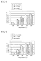
- Figure 8 shows the relative amounts of oxygen storage of the above oxygen storage components at different measurement temperatures when the amount of oxygen storage of Rh-CeZrNdO at a measurement temperature of 300°C is assumed as 1. At any of the measurement temperatures, Rh-CeZrNdO exhibited the largest amount of oxygen storage, Rh-CeZrO the second largest amount of oxygen storage, and Rh/CeZrO the smallest amount of oxygen storage.
- Figure 9 shows the relative rates of oxygen storage of the above oxygen storage components at different measurement temperatures when the rate of oxygen storage of Rh-CeZrNdO at a measurement temperature of 300°C is assumed as 1. At any of the measurement temperatures, Rh-CeZrNdO exhibited the highest rate of oxygen storage, Rh-CeZrO the second highest rate of oxygen storage, and Rh/CeZrO the lowest rate of oxygen storage.
- Example 1 the catalysts A and C were employed as the upstream and downstream catalysts 3 and 4, respectively. Therefore, the oxygen storage component (Rh-CeZrNdO) in the upstream catalyst 3 (i.e., the catalyst A) has a larger amount of oxygen storage and a higher rate of oxygen storage than the oxygen storage component (Rh/CeZrO) in the downstream catalyst 4 (i.e., the catalyst C).
- the total catalyst capacity of the upstream and downstream catalysts 3 and 4 in Example 1 is 1.9L.
- the catalyst C was employed as each of the upstream and downstream catalysts 3 and 4. Therefore, the oxygen storage component in the upstream catalyst 3 is equal in the amount and rate of oxygen storage to the oxygen storage component in the downstream catalyst 4.
- the total catalyst capacity of the upstream and downstream catalysts 3 and 4 in Comparative Example is 2.0L.
- the catalytic converters of Examples 1 and 2 and Comparative Example were measured in terms of light-off temperatures T50 and high-temperature catalytic conversion efficiencies C400 for conversion of HC, CO and NOx using a model gas flow reactor and an exhaust gas analyzer.
- Each of the catalysts A to C in Examples 1 and 2 and Comparative Example was previously aged by keeping it at 1000°C under atmospheric conditions for 24 hours.
- the measurement of T50 and C400 for each catalytic converter was carried out after a model gas of rich A/F ratio (temperature: 600°C) was allowed to flow through the catalytic converter for 10 minutes.
- T50 indicates the gas temperature at the entrance of each catalytic converter when the gas conversion efficiency reaches 50% after the temperature of the model gas flowing into the converter is gradually increased from normal temperature.
- C400 indicates the catalytic conversion efficiency when the gas temperature at the catalytic converter entrance is 400°C.
- the model gas had an A/F ratio of 14.7 ⁇ 1.2. Specifically, a mainstream gas was allowed to flow constantly at an A/F ratio of 14.7 and a predetermined amount of gas for changing the A/F ratio was added in pulses, so that the A/F ratio was forcedly periodically varied with an amplitude of ⁇ 1.2.
- a frequency of variations of 1Hz was used in Example 1, a frequency of variations of 2Hz in Example 2, and two types of frequencies of variations of 1Hz and 2Hz in Comparative Example.
- the flow rate of the model gas was common to Examples 1 and 2 and Comparative Example. On the other hand, since Examples 1 and 2 and Comparative Example have different catalyst capacities, they had different space velocities SV.
- the space velocity SV in Example 1 was 63200 h -1
- the space velocity in Example 2 was 66700 h -1
- the space velocity in Comparative Example was 60000 h -1 .
- the rate of temperature rise of the model gas was 30°C/min. The measurement results are shown in Table 1.
- Example 1 In comparison between Example 1 (frequency: 1Hz) and Comparative Example (frequency: 1Hz), Example 1 exhibited better results for both T50 and C400 than Comparative Example though the former has a higher space velocity than the latter. The reason is believed to be that Rh-CeZrNdO having a larger amount of oxygen storage was used as an oxygen storage component for the upstream catalyst 3.
- Example 2 It can be said that the above improvement in T50 of Example 2 was effected by the use of Rh-CeZrO having relatively good amount and rate of oxygen storage in the downstream catalyst 4 in Example 2. But, it is rather believed that the above improvement was more significantly effected by the fact that the oxygen storage component Rh-CeZrNdO in the upstream catalyst 3 has a high rate of oxygen storage. As a result of this, the values of C400 in Example 2 were increased to near 100%. Particularly considering that Example 2 has a higher space velocity than Example 1, it can be understood that Example 2 has an excellent catalyst composition.
- one or more kinds of additional catalytic metals may be post-carried on each of the oxygen storage components in the upstream and downstream catalysts.
Landscapes
- Chemical & Material Sciences (AREA)
- Engineering & Computer Science (AREA)
- Chemical Kinetics & Catalysis (AREA)
- Materials Engineering (AREA)
- Combustion & Propulsion (AREA)
- Organic Chemistry (AREA)
- Mechanical Engineering (AREA)
- General Engineering & Computer Science (AREA)
- Health & Medical Sciences (AREA)
- Biomedical Technology (AREA)
- Environmental & Geological Engineering (AREA)
- Analytical Chemistry (AREA)
- General Chemical & Material Sciences (AREA)
- Oil, Petroleum & Natural Gas (AREA)
- Exhaust Gas Treatment By Means Of Catalyst (AREA)
- Catalysts (AREA)
- Exhaust Gas After Treatment (AREA)
Abstract
Description
- This invention relates to exhaust gas catalytic converters useful for purifying exhaust gas from automobile engines.
- Many of recent automobile exhaust gas purification techniques use a close-coupled catalyst (manifold catalyst) directly coupled to an exhaust manifold for early catalytic activation after engine start, in combination with one or more underfloor catalysts disposed under the vehicle floor to convert part of exhaust gas which the close-coupled catalyst has failed to convert. Such underfloor catalysts are also disposed as close to the engine as possible for their early catalytic activation. Therefore, the underfloor catalysts have a problem that catalytic precious metal particles are sintered by the heat of the exhaust gas, like the close-coupled catalyst.
- Inventors have proposed, as a solution to the above problem, an exhaust gas purification catalyst disclosed in
Japanese Unexamined Patent Publication No. 2004-174490 - The air-fuel ratio of the engine always varies. Three-way catalysts are required to absorb variations in the air-fuel ratio to provide ensured exhaust gas purification. The above patent document also discloses that since the oxygen storage component has a high rate of oxygen storage, it exhibits a high response of oxygen storage and release to variations in the air-fuel ratio, thereby enhancing the exhaust gas conversion efficiency.
- To satisfy not only the requirement for provision of the response of the catalyst to variations in the air-fuel ratio but also the requirement for provision of the thermal resistance of the catalyst, conventional approaches have been directed to increasing the amount of catalyst disposed in the exhaust passage of the engine or increasing the capacity of the catalyst. However, the recent trend of motor vehicles is toward extending the passengers room while reducing the engine room for improvement in comfortableness to ride in the vehicle and engines are recently upsizing. Therefore, the close-coupled catalyst is required to enhance the arrangeability in the engine room (reduce the size). The underfloor catalyst is likewise required to enhance the arrangeability in consideration of the relations with members arranged under the vehicle floor, such as a propeller shaft and a suspension cross member.
- With the foregoing in mind, an object of the present invention is to ensure the improvement in catalytic performance of an exhaust gas catalytic converter, which is an essential performance thereof, ensure the thermal resistance thereof and downsize the converter, i.e., improve the arrangeability thereof.
- To attain the above object, in the present invention, an upstream catalyst and a downstream catalyst, each acting as a three-way catalyst, are arranged in an exhaust passage of an engine and an oxygen storage component in the upstream catalyst is doped with Rh, more specifically, Rh atoms are placed at or between crystal lattice points of a mixed oxide which is the oxygen storage component, thereby improving the thermal resistance, exhaust gas purification performance and oxygen storage capacity of the upstream catalyst. More specific solutions are described below.
- A first solution of the present invention is directed to an exhaust gas catalytic converter having an upstream catalyst and a downstream catalyst which are arranged in upstream and downstream sides of an engine exhaust passage through which exhaust gas flows, wherein
each of the upstream catalyst and the downstream catalyst contains an oxygen storage component, and
the oxygen storage component in the upstream catalyst has a structure in which Rh atoms are placed at or between crystal lattice points of a mixed oxide containing Ce and Zr and has a larger amount of oxygen storage than the oxygen storage component in the downstream catalyst under the same temperature conditions. - In the first solution, since the oxygen storage component in the upstream catalyst has a larger amount of oxygen storage than that in the downstream catalyst under the same temperature conditions, this is advantageous in absorbing/releasing oxygen from/to exhaust gas without shortage according to variations in the engine air-fuel ratio, even variations with a large amplitude (for example, even if the air-fuel ratio varies with an amplitude of ±0.9 or more with respect to the stoichiometric air-fuel ratio of 14.7).
- Therefore, the upstream catalyst is restrained from being reduced in exhaust gas conversion efficiency owing to variations in the air-fuel ratio. This makes it possible to avoid upsizing of the catalyst for ensuring exhaust gas purification performance, or is advantageous in downsizing the catalytic converter, which improves the arrangeability of the catalytic converter. Further, variations in the oxygen concentration of exhaust gas can be absorbed by oxygen storage/release in the upstream catalyst even if the air-fuel ratio varies with such a large amplitude as described above. Therefore, the downstream catalyst can efficiently convert exhaust gas in spite that its oxygen storage component has a relatively small amount of oxygen storage. This is advantageous in downsizing the catalytic converter or improving the arrangeability of the catalytic converter, like the upstream catalyst.
- Furthermore, Rh in the oxygen storage component in the upstream catalyst not only acts to increase the amount of oxygen storage but also act as a catalytic precious metal to convert HC (hydrocarbon), CO (carbon monoxide) and NOx (nitrogen oxides). In addition, Rh atoms are placed at or between crystal lattice points of the mixed oxide to strongly bind to the mixed oxide. Therefore, Rh particles are restrained from being sintered by the heat of exhaust gas, prevents the structure of the mixed oxide itself from being broken down by the heat of exhaust gas and in turn prevents the mixed oxide from deteriorating the oxygen storage capacity.
- The upstream catalyst may be a close-coupled catalyst disposed in an automobile engine room or an underfloor catalyst. In the former case, an underfloor catalyst can be used as the downstream catalyst. In the latter case, the downstream catalyst can be an underfloor catalyst disposed downstream of the underfloor catalyst disposed in the upstream side of the exhaust gas flow. This is valid for the following other solutions of the invention.
- The above first solution does not limit the oxygen storage component for use in the downstream catalyst to one having a structure in which Rh atoms are placed at or between crystal lattice points of a mixed oxide containing Ce and Zr. So long as the oxygen storage component in the upstream catalyst has a larger amount of oxygen storage than the oxygen storage component in the downstream catalyst, any types of oxygen storage components can be used in the downstream catalyst.
- A second solution of the invention is characterized in that in the first solution,
the oxygen storage component in the downstream catalyst has a structure in which Rh atoms are placed at or between crystal lattice points of a mixed oxide containing different ingredients from the oxygen storage component in the upstream catalyst, and
the oxygen storage component in the upstream catalyst has a higher rate of oxygen storage than the oxygen storage component in the downstream catalyst under the same temperature conditions. - At high frequencies of variations in the engine air-fuel ratio (for example, 1Hz or more), even if an oxygen storage component having a high amount of oxygen storage is employed in the upstream catalyst, oxygen storage/release may lag behind variations in the air-fuel ratio so that an expected exhaust gas purification cannot be attained. In the second solution, since the oxygen storage component in the upstream catalyst has a higher rate of oxygen storage than the oxygen storage component in the downstream catalyst, oxygen storage/release can take place with good response to variations in the air-fuel ratio, thereby enhancing the exhaust gas purification performance.
- A third solution of the invention is characterized in that in the second solution,
the oxygen storage component in the upstream catalyst has a structure in which Rh atoms are placed at or between crystal lattice points of a Ce-Zr-Nd ternary oxide, and
the oxygen storage component in the downstream catalyst has a structure in which Rh atoms are placed at or between crystal lattice points of a Ce-Zr binary oxide. - As will be obvious from the later-described experimental data, the oxygen storage component in which Rh atoms are placed at or between crystal lattice points of a Ce-Zr-Nd ternary oxide has a higher rate of oxygen storage than the oxygen storage component in which Rh atoms are placed at or between crystal lattice points of a Ce-Zr binary oxide. Therefore, the third solution can increase the rate of oxygen storage of the oxygen storage component in the upstream catalyst to ensure the exhaust gas purification performance at high frequencies of variations in the air-fuel ratio.
- A fourth solution of the invention is directed to an exhaust gas catalytic converter having an upstream catalyst and a downstream catalyst which are arranged in upstream and downstream sides of an engine exhaust passage through which exhaust gas flows, wherein
the upstream catalyst comprises an inner catalytic layer disposed on a support and an outer catalytic layer disposed on the inner catalytic layer, and
the outer catalytic layer contains an oxygen storage component in which Rh atoms are placed at or between crystal lattice points of a mixed oxide containing Ce, Zr and Nd. - In the fourth solution, since the oxygen storage component contained in the outer catalytic layer of the upstream catalyst has a structure in which Rh atoms are placed at or between crystal lattice points of a mixed oxide containing Ce, Zr and Nd, it has a large amount of oxygen storage and a high rate of oxygen storage. In the upstream catalyst, since such an oxygen storage component is contained in the outer catalytic layer directly exposed to exhaust gas, variations in the air-fuel ratio can be efficiently absorbed by the oxygen storage component. This makes it possible to avoid upsizing of the catalyst for ensuring exhaust gas purification performance, or is advantageous in downsizing the catalytic converter, which improves the arrangeability of the catalytic converter. Further, since variations in the oxygen concentration of exhaust gas can be absorbed by the upstream catalyst, the downstream catalyst can efficiently convert exhaust gas. This is advantageous in downsizing the catalytic converter or improving the arrangeability of the catalytic converter, like the upstream catalyst.
- Furthermore, Rh in the oxygen storage component in the upstream catalyst not only acts to increase the amount of oxygen storage but also act as a catalytic precious metal to convert HC, CO and NOx. In addition, Rh atoms are placed at or between crystal lattice points of the mixed oxide to strongly bind to the mixed oxide. Therefore, Rh particles are restrained from being sintered by the heat of exhaust gas, prevents the structure of the mixed oxide itself from being broken down by the heat of exhaust gas and in turn prevents the mixed oxide from deteriorating the oxygen storage capacity.
- A fifth solution of the invention is characterized in that in the fourth solution, the downstream catalyst contains at least one of an oxygen storage component in which Rh atoms are placed at or between crystal lattice points of a mixed oxide containing Ce and Zr and an oxygen storage component in which Rh particles are carried on a mixed oxide containing Ce and Zr.
- In the fifth solution, variations in the air-fuel ratio can also be absorbed by the oxygen storage component in the downstream catalyst. In addition, Rh is contained in the oxygen storage component. Therefore, this solution is further advantageous in efficiently converting exhaust gas.
- A sixth solution of the invention is characterized in that in the fourth or fifth solution, the inner and outer catalytic layers of the upstream catalyst contain Pd and Pt, respectively.
- In the sixth solution, Pd in the inner catalytic layer and Pt in the outer catalytic layer are restrained from being sintered and alloyed with each other. Further, since Pd is protected by the outer catalytic layer, it can be restrained from being poisoned with S (sulfur) and P (phosphor).
-
- Figure 1 is a diagram showing the structure of an exhaust gas catalytic converter.
- Figure 2 is a diagram showing the structure of a catalyst A.
- Figure 3 is a diagram showing the structure of a catalyst B.
- Figure 4 is a diagram showing the structure of a catalyst C.
- Figure 5 is a schematic diagram showing a measurement device for measuring oxygen storage properties.
- Figure 6 is a time chart showing how the measurement device generates O2 pulses and CO pulses.
- Figure 7 is a graph showing the time variations of the signal intensity of mass number 32 measured by a mass spectrometer in the measurement device.
- Figure 8 is a graph for comparison among relative amounts of oxygen storage of three kinds of oxygen storage components.
- Figure 9 is a graph for comparison among relative rates of oxygen storage of the three kinds of oxygen storage components.
- An embodiment of the present invention will be described in details below with reference to the drawings.
- In Figure 1, the
reference numeral 1 denotes an automobile engine, thereference numeral 2 denotes an exhaust passage of the engine, thereference numeral 3 denotes an upstream catalyst (three-way catalyst) arranged in an upstream side of theexhaust passage 2 through which exhaust gas flows, and thereference numeral 4 denotes a downstream catalyst (three-way catalyst) arranged in a downstream side of theexhaust passage 2. - In order to construct each of catalytic converters of Examples and Comparative Example using the catalyst arrangement shown in Figure 1, three types of catalysts A, B and C shown in Figures 2, 3 and 4, respectively, were prepared. The three types of catalysts were each formed by stacking an inner
catalytic layer 6 and an outercatalytic layer 7 on thewall 5 of each of cells forming a honeycomb support (hereinafter, simply referred to as a support) in an arrangement that the innercatalytic layer 6 is located near to thecell wall 5 and the outercatalytic layer 7 is directly exposed to exhaust gas. - The inner
catalytic layer 6 of the catalyst A shown in Figure 2 contains Pd/alumina as a catalytic component. Pd/alumina was obtained by post-carrying Pd as a catalytic metal on powders of gamma-alumina containing 4 mass% of La. The process herein called "post-carrying" means carrying a catalytic metal on a support material such as gamma-alumina powder by bringing the support material into contact with a solution of the catalytic metal and then calcining it. Specifically, evaporation to dryness was employed as the post-carrying process in this embodiment. - The outer
catalytic layer 7 of the catalyst A contains a mixture of Rh-CeZrNdO and Pt/alumina as a catalytic component. Rh-CeZrNdO has a structure in which Rh atoms are placed at or between crystal lattice points of a Ce-Zr-Nd ternary oxide. Pt/alumina was obtained by post-carrying Pt as a catalytic metal on gamma-alumina powders containing 4 mass% of La and prepared in the same manner as for Pd/alumina. - Rh-CeZrNdO was prepared by coprecipitation using as source materials respective solutions of Ce, Zr, Nd and Rh. The preparation method is described below. First, respective predetermined amounts of zirconium oxynitrate solution, cerous nitrate solution, neodymium (III) nitrate solution and rhodium nitrate solution are mixed with water to make a total volume of 300 mL of mixed solution, and the mixed solution is stirred at room temperature for about an hour. The mixed solution is heated to 80°C and then mixed with 50 mL of 28% aqueous ammonia by adding the aqueous ammonia prepared in another beaker to the mixed solution at once while stirring strongly and rapidly with a glass bar. The adding and mixing is completed within one second. The white-turbid solution resulting from the mixture with aqueous ammonia is allowed to stand for a diel to produce a cake, and the cake is centrifuged and sufficiently rinsed in water. The water-rinsed cake is dried at approximately 150°C, and then calcined under the condition of keeping it at 400°C for five hours and then keeping it at 500°C for two hours, thereby obtaining a Rh-CeZrNdO mixed oxide.
- The resultant Rh-CeZrNdO mixed oxide is produced by coprecipitation by doping the mixed oxide with Rh as a precious metal component. Therefore, Rh atoms are placed at crystal lattice points of the mixed oxide like Ce and Zr atoms and, in other words, Rh atoms are strongly bound to the mixed oxide. Alternatively, Rh atoms are placed between crystal lattice points of the mixed oxide. In either case, Rh atoms are evenly dispersed on and in each crystallite of the mixed oxide.
- In the formation of the inner
catalytic layer 6, Pd/alumina and an alumina binder were weighed and mixed so that the amounts of them when carried on the support could reach predetermined amounts, respectively. Then, ion-exchange water was added to the mixture thereby preparing a slurry. The slurry was washcoated on the support by immersing the support in the slurry, picking it up from the slurry, and then blowing out an excess amount of slurry. Next, the washcoated support was dried at a temperature of 150°C for an hour and then calcined at a temperature of 540°C for two hours, thereby forming an innercatalytic layer 6. - In the formation of the outer
catalytic layer 7, Rh-CeZrNdO, Pt/alumina and an alumina binder were weighed and mixed so that the amounts of them when carried on the support could reach predetermined amounts, respectively. Then, ion-exchange water was added to the mixture thereby preparing a slurry. The slurry was washcoated on the support on which the innercatalytic layer 6 was formed, and dried and calcined in the same manner as in the formation of the innercatalytic layer 6, thereby forming an outercatalytic layer 7. - The capacity (support capacity) of the catalyst A is 0.9L. The Pd/alumina and Pt/alumina were carried on the support so that gamma-alumina, Pd and Pt were at 50g, 0.1 g and 0.1 g, respectively, per 1L of the support. The Rh-CeZrNdO was carried on the support so that it was at 100g per 1 L of the support. The mass ratio between oxides in the Rh-CeZrNdO mixed oxide was CeO2:ZrO2:Nd2O3 = 22:68:10. The amount of Rh in the mixed oxide was 0.116 mass%.
- For the catalyst B shown in Figure 3, the inner
catalytic layer 6 contains Pd/alumina as a catalytic component like the catalyst A, but the outercatalytic layer 7 contains a mixture of Rh-CeZrO and Pt/alumina. That is, the catalyst B is different from the catalyst A in that it employs Rh-CeZrO. Rh-CeZrO has a structure in which Rh atoms are placed at or between crystal lattice points of a Ce-Zr binary oxide and was prepared by coprecipitation like Rh-CeZrNdO of the catalyst A. - The inner and outer
catalytic layers - For the catalyst C shown in Figure 4, the inner
catalytic layer 6 contains Pd/alumina as a catalytic component like the catalyst A, but the outercatalytic layer 7 contains a mixture of Rh/CeZrO and Pt/alumina. That is, the catalyst C is different from the catalyst A in that it employs Rh/CeZrO. Rh/CeZrO was obtained by post-carrying Rh on a Ce-Zr binary oxide. - The inner and outer
catalytic layers - Each of the Rh-CeZrNdO, Rh-CeZrO and Rh/CeZrO in the catalysts A to C acts as an oxygen storage component. These oxygen storage components were measured in terms of the amount and rate of oxygen storage. The measurement methods will be described below.
- Each of the oxygen storage components was mixed with alumina and prepared into a granular sample. Each granular sample was aged (heated at 1000°C under atmospheric conditions for 24 hours) and then measured in terms of the rate of oxygen storage under excess oxygen conditions. Figure 5 shows a measurement device for the measurement. In this figure, the
reference numeral 11 denotes a glass tube for holding asample 12. Thesample 12 is heated to and maintained at a predetermined temperature by aheater 13. Theglass tube 11 is connected, upstream of thesample 12, with apulsed gas generator 14 for supplying pulsed gases of O2, CO and He individually. Downstream of thesample 12, theglass tube 11 is also connected with amass spectrometer 17 through acapillary column 16 and provided with anexhaust part 18. Athermocouple 19 for temperature control is attached to the portion of theglass tube 11 in which a sample is to be held. - In measurement, the sample temperature in the
glass tube 11 was kept at the predetermined temperature. Under this condition, as shown in Figure 6, a cycle of generation of an O2 pulse (with a width of 25ms) every 15 seconds was repeated several times and CO pulses (with a width of 50ms) were then generated after four seconds delay from each of subsequent generations of O2 pulses, while exhaust gas was constantly discharged from theexhaust part 18. During the time, themass spectrometer 17 was used to measure the time variation of the signal intensity of mass number 32 (the amount of O2) in each cycle. - Thus, as shown in Figure 7, determination was made of the time variation of the signal intensity of mass number 32 before supply of CO pulses (data when the change in the signal intensity became stable because of saturation of oxygen storage of the sample during the period of generation of O2 pulses alone) and the time variation of the signal intensity of mass number 32 after supply of CO pulses (data when the change in the signal intensity became stable during the period of generation of CO pulses after generation of O2 pulses alone). In this determination results, the reason for the difference between the signal intensities before and after supply of CO pulses is that the sample stored oxygen.
- More specifically, the signal intensity before supply of CO pulses is based on the observation of the amount of oxygen having passed through the sample in which oxygen storage is saturated. Therefore, it almost exactly reflects the amount of oxygen supplied by O2 pulses. On the other hand, after supply of CO pulses, supplied CO pulses allow O2 to be released from inside the sample and thereby changed into CO2, and in turn the corresponding amount of oxygen to the released oxygen is stored in the sample. Therefore, the signal intensity after supply of CO pulses reflects the amount of oxygen obtained by subtracting the amount of oxygen stored in the sample from the amount of oxygen supplied by O2 pulses. Hence, the amount of oxygen stored (i.e., the amount of oxygen storage) can be obtained by subtracting the signal intensity after supply of CO pulses from the signal intensity before supply of CO pulses.
- Figure 8 shows the relative amounts of oxygen storage of the above oxygen storage components at different measurement temperatures when the amount of oxygen storage of Rh-CeZrNdO at a measurement temperature of 300°C is assumed as 1. At any of the measurement temperatures, Rh-CeZrNdO exhibited the largest amount of oxygen storage, Rh-CeZrO the second largest amount of oxygen storage, and Rh/CeZrO the smallest amount of oxygen storage.
- Figure 9 shows the relative rates of oxygen storage of the above oxygen storage components at different measurement temperatures when the rate of oxygen storage of Rh-CeZrNdO at a measurement temperature of 300°C is assumed as 1. At any of the measurement temperatures, Rh-CeZrNdO exhibited the highest rate of oxygen storage, Rh-CeZrO the second highest rate of oxygen storage, and Rh/CeZrO the lowest rate of oxygen storage.
- In Example 1, the catalysts A and C were employed as the upstream and
downstream catalysts downstream catalysts - In Example 2, the catalysts A and B were employed as the upstream and
downstream catalysts downstream catalysts - In Comparative Example, the catalyst C was employed as each of the upstream and
downstream catalysts upstream catalyst 3 is equal in the amount and rate of oxygen storage to the oxygen storage component in thedownstream catalyst 4. The total catalyst capacity of the upstream anddownstream catalysts - The catalytic converters of Examples 1 and 2 and Comparative Example were measured in terms of light-off temperatures T50 and high-temperature catalytic conversion efficiencies C400 for conversion of HC, CO and NOx using a model gas flow reactor and an exhaust gas analyzer. Each of the catalysts A to C in Examples 1 and 2 and Comparative Example was previously aged by keeping it at 1000°C under atmospheric conditions for 24 hours. The measurement of T50 and C400 for each catalytic converter was carried out after a model gas of rich A/F ratio (temperature: 600°C) was allowed to flow through the catalytic converter for 10 minutes. T50 indicates the gas temperature at the entrance of each catalytic converter when the gas conversion efficiency reaches 50% after the temperature of the model gas flowing into the converter is gradually increased from normal temperature. C400 indicates the catalytic conversion efficiency when the gas temperature at the catalytic converter entrance is 400°C.
- The model gas had an A/F ratio of 14.7±1.2. Specifically, a mainstream gas was allowed to flow constantly at an A/F ratio of 14.7 and a predetermined amount of gas for changing the A/F ratio was added in pulses, so that the A/F ratio was forcedly periodically varied with an amplitude of±1.2. A frequency of variations of 1Hz was used in Example 1, a frequency of variations of 2Hz in Example 2, and two types of frequencies of variations of 1Hz and 2Hz in Comparative Example. The flow rate of the model gas was common to Examples 1 and 2 and Comparative Example. On the other hand, since Examples 1 and 2 and Comparative Example have different catalyst capacities, they had different space velocities SV. The space velocity SV in Example 1 was 63200 h-1, the space velocity in Example 2 was 66700 h-1, and the space velocity in Comparative Example was 60000 h-1. The rate of temperature rise of the model gas was 30°C/min. The measurement results are shown in Table 1.
Table 1 Conditions T50 (°C) C400 (%) Gas composition Frequency SV HC CO NOx HC CO NOx Example 1 A/F=14.7±1.2 1Hz 63200/h 268 252 249 98 97 94 Example 2 A/F=14.7±1.2 2Hz 66700/h 261 247 243 99 98 96 Comparative Example A/F =14.7±1.2 1Hz 60000/h 275 260 256 93 91 80 A/F =14.7±1.2 2Hz 60000/h 272 258 253 98 95 91 - In comparison between Example 1 (frequency: 1Hz) and Comparative Example (frequency: 1Hz), Example 1 exhibited better results for both T50 and C400 than Comparative Example though the former has a higher space velocity than the latter. The reason is believed to be that Rh-CeZrNdO having a larger amount of oxygen storage was used as an oxygen storage component for the
upstream catalyst 3. - Further, the results of Comparative Example show that an increase of the frequency of variations from 1Hz to 2Hz is advantageous to exhaust gas conversion. On the other hand, the degree of improvement in T50 of Example 2 (frequency: 2Hz) over Example 1 (frequency: 1Hz) is higher than that of 2Hz over 1Hz in Comparative Example.
- It can be said that the above improvement in T50 of Example 2 was effected by the use of Rh-CeZrO having relatively good amount and rate of oxygen storage in the
downstream catalyst 4 in Example 2. But, it is rather believed that the above improvement was more significantly effected by the fact that the oxygen storage component Rh-CeZrNdO in theupstream catalyst 3 has a high rate of oxygen storage. As a result of this, the values of C400 in Example 2 were increased to near 100%. Particularly considering that Example 2 has a higher space velocity than Example 1, it can be understood that Example 2 has an excellent catalyst composition. - In the present invention, one or more kinds of additional catalytic metals may be post-carried on each of the oxygen storage components in the upstream and downstream catalysts.
- The present invention is not limited to the embodiment as described above but includes various changes and modifications without departing from the spirit and scope of the invention defined by the following claims.
Claims (6)
- An exhaust gas catalytic converter having an upstream catalyst and a downstream catalyst which are arranged in upstream and downstream sides of an engine exhaust passage through which exhaust gas flows, wherein
each of the upstream catalyst and the downstream catalyst contains an oxygen storage component, and
the oxygen storage component in the upstream catalyst has a structure in which Rh atoms are placed at or between crystal lattice points of a mixed oxide containing Ce and Zr and has a larger amount of oxygen storage than the oxygen storage component in the downstream catalyst under the same temperature conditions. - The exhaust gas catalytic converter of claim 1, wherein
the oxygen storage component in the downstream catalyst has a structure in which Rh atoms are placed at or between crystal lattice points of a mixed oxide containing different ingredients from the oxygen storage component in the upstream catalyst, and
the oxygen storage component in the upstream catalyst has a higher rate of oxygen storage than the oxygen storage component in the downstream catalyst under the same temperature conditions. - The exhaust gas catalytic converter of claim 2, wherein
the oxygen storage component in the upstream catalyst has a structure in which Rh atoms are placed at or between crystal lattice points of a Ce-Zr-Nd ternary oxide, and
the oxygen storage component in the downstream catalyst has a structure in which Rh atoms are placed at or between crystal lattice points of a Ce-Zr binary oxide. - An exhaust gas catalytic converter having an upstream catalyst and a downstream catalyst which are arranged in upstream and downstream sides of an engine exhaust passage through which exhaust gas flows, wherein
the upstream catalyst comprises an inner catalytic layer disposed on a support and an outer catalytic layer disposed on the inner catalytic layer, and
the outer catalytic layer contains an oxygen storage component in which Rh atoms are placed at or between crystal lattice points of a mixed oxide containing Ce, Zr and Nd. - The exhaust gas catalytic converter of claim 4, wherein the downstream catalyst contains at least one of an oxygen storage component in which Rh atoms are placed at or between crystal lattice points of a mixed oxide containing Ce and Zr and an oxygen storage component in which Rh particles are carried on a mixed oxide containing Ce and Zr.
- The exhaust gas catalytic converter of claim 4 or 5, wherein the inner and outer catalytic layers of the upstream catalyst contain Pd and Pt, respectively.
Applications Claiming Priority (1)
| Application Number | Priority Date | Filing Date | Title |
|---|---|---|---|
| JP2005116627A JP4654746B2 (en) | 2005-04-14 | 2005-04-14 | Exhaust gas purification catalyst device |
Publications (3)
| Publication Number | Publication Date |
|---|---|
| EP1712279A2 true EP1712279A2 (en) | 2006-10-18 |
| EP1712279A3 EP1712279A3 (en) | 2006-12-27 |
| EP1712279B1 EP1712279B1 (en) | 2012-05-23 |
Family
ID=36685839
Family Applications (1)
| Application Number | Title | Priority Date | Filing Date |
|---|---|---|---|
| EP06006448A Ceased EP1712279B1 (en) | 2005-04-14 | 2006-03-28 | Exhaust gas catalytic converter |
Country Status (4)
| Country | Link |
|---|---|
| US (1) | US7344683B2 (en) |
| EP (1) | EP1712279B1 (en) |
| JP (1) | JP4654746B2 (en) |
| CN (1) | CN1846839B (en) |
Cited By (8)
| Publication number | Priority date | Publication date | Assignee | Title |
|---|---|---|---|---|
| EP1900427A1 (en) * | 2006-09-15 | 2008-03-19 | Daiichi Kigenso Kagaku Kogyo Co., Ltd. | Catalyst system for vehicle exhaust gas purification devices, exhaust gas purification device using the same, and method for purification of exhaust gases |
| US7785545B2 (en) | 2006-09-06 | 2010-08-31 | Mazda Motor Corporation | Exhaust gas catalytic conversion system |
| EP1772184A3 (en) * | 2005-10-04 | 2011-05-25 | Heesung Engelhard Corporation | Catalyst for oxidizing emissions from compressed natural gas vehicles |
| WO2011080567A1 (en) * | 2010-01-04 | 2011-07-07 | Toyota Jidosha Kabushiki Kaisha | Exhaust gas purifying catalyst |
| WO2012069405A1 (en) * | 2010-11-22 | 2012-05-31 | Umicore Ag & Co. Kg | Three-way catalytic system having an upstream multi - layer catalyst |
| WO2012088373A3 (en) * | 2010-12-22 | 2013-02-14 | Pacific Industrial Development Corporation | Catalyst support materials with oxygen storage capacity (osc) and method of making thereof |
| US8557204B2 (en) | 2010-11-22 | 2013-10-15 | Umicore Ag & Co. Kg | Three-way catalyst having an upstream single-layer catalyst |
| US10232348B2 (en) | 2010-12-22 | 2019-03-19 | Pacific Industrial Development Corporation | Doped catalyst support materials having oxygen storage capacity (OSC) and method of making thereof |
Families Citing this family (15)
| Publication number | Priority date | Publication date | Assignee | Title |
|---|---|---|---|---|
| JP4687389B2 (en) * | 2005-10-26 | 2011-05-25 | マツダ株式会社 | Exhaust gas purification catalyst |
| JP4826337B2 (en) * | 2006-05-23 | 2011-11-30 | マツダ株式会社 | Exhaust gas purification catalyst and exhaust gas purification method |
| JP4793316B2 (en) * | 2007-04-20 | 2011-10-12 | トヨタ自動車株式会社 | Sulfur storage catalyst |
| JP5326251B2 (en) * | 2007-10-02 | 2013-10-30 | マツダ株式会社 | Exhaust gas purification catalyst device |
| US20090175773A1 (en) * | 2008-01-08 | 2009-07-09 | Chen Shau-Lin F | Multilayered Catalyst Compositions |
| JP5428774B2 (en) * | 2009-11-10 | 2014-02-26 | マツダ株式会社 | Exhaust gas purification catalyst |
| JP5463861B2 (en) * | 2009-11-10 | 2014-04-09 | マツダ株式会社 | Exhaust gas purification catalyst |
| JP5428773B2 (en) * | 2009-11-10 | 2014-02-26 | マツダ株式会社 | Exhaust gas purification catalyst |
| JP5594161B2 (en) | 2011-01-26 | 2014-09-24 | マツダ株式会社 | Exhaust gas purification catalyst device |
| JP2012154259A (en) | 2011-01-26 | 2012-08-16 | Mazda Motor Corp | Exhaust gas purification catalytic system |
| JP2014097459A (en) * | 2012-11-14 | 2014-05-29 | Cataler Corp | Catalyst for purifying exhaust gases |
| JP5757297B2 (en) * | 2013-01-23 | 2015-07-29 | トヨタ自動車株式会社 | Catalytic converter |
| US9421528B2 (en) * | 2013-02-25 | 2016-08-23 | Umicore Shokubai Japan Co., Ltd. | Exhaust gas purifying catalyst and exhaust gas purification method using same |
| JP6372513B2 (en) * | 2016-04-13 | 2018-08-15 | トヨタ自動車株式会社 | Catalytic converter |
| EP3978115A4 (en) * | 2019-05-31 | 2023-07-12 | Mitsui Mining & Smelting Co., Ltd. | EMISSION CONTROL CATALYST AND EMISSION CONTROL SYSTEM WITH THE EMISSION CONTROL CATALYST |
Citations (1)
| Publication number | Priority date | Publication date | Assignee | Title |
|---|---|---|---|---|
| JP2004174490A (en) | 2002-11-14 | 2004-06-24 | Mazda Motor Corp | Catalyst material and method for producing the same |
Family Cites Families (26)
| Publication number | Priority date | Publication date | Assignee | Title |
|---|---|---|---|---|
| DE4003939A1 (en) * | 1990-02-09 | 1991-08-14 | Degussa | Noble metal alumina catalyst contg. oxide promoter for gas purificn. - doped with base metal for cold start property and resistance to lean gas |
| US5057483A (en) * | 1990-02-22 | 1991-10-15 | Engelhard Corporation | Catalyst composition containing segregated platinum and rhodium components |
| GB9226434D0 (en) * | 1992-12-18 | 1993-02-10 | Johnson Matthey Plc | Catalyst |
| JP3273820B2 (en) | 1993-02-26 | 2002-04-15 | 株式会社三徳 | Cerium-containing composite oxide having oxygen absorbing / releasing ability and method for producing the same |
| DE69417889T2 (en) * | 1993-06-25 | 1999-10-07 | Engelhard Corp., Iselin | COMPOSITE LAYER CATALYST |
| CN1205652A (en) * | 1995-12-21 | 1999-01-20 | 恩格尔哈德公司 | Engine exhaust gas treatment device and application method |
| US6087298A (en) * | 1996-05-14 | 2000-07-11 | Engelhard Corporation | Exhaust gas treatment system |
| US5981427A (en) * | 1996-09-04 | 1999-11-09 | Engelhard Corporation | Catalyst composition |
| WO1998011978A1 (en) * | 1996-09-19 | 1998-03-26 | Precision Combustion Inc. | Catalytic method |
| GB9813367D0 (en) * | 1998-06-22 | 1998-08-19 | Johnson Matthey Plc | Catalyst |
| JP4275801B2 (en) | 1999-04-22 | 2009-06-10 | 株式会社キャタラー | Exhaust gas purification catalyst |
| JP3715211B2 (en) * | 2000-09-07 | 2005-11-09 | 本田技研工業株式会社 | Exhaust gas purification device for internal combustion engine |
| JP2002355561A (en) * | 2001-03-26 | 2002-12-10 | Mazda Motor Corp | Exhaust gas purification catalyst and exhaust gas purification method |
| US20030039597A1 (en) * | 2001-08-24 | 2003-02-27 | Engelhard Corporation | Close coupled catalyst with a SOx trap and methods of making and using the same |
| JP3855266B2 (en) * | 2001-11-01 | 2006-12-06 | 日産自動車株式会社 | Exhaust gas purification catalyst |
| JP2003246624A (en) | 2002-02-25 | 2003-09-02 | Toyota Motor Corp | Method for producing pyrochlore type oxide |
| JP2004074138A (en) | 2002-06-17 | 2004-03-11 | Toyota Motor Corp | Exhaust gas purification catalyst and exhaust gas purification method |
| US20040001781A1 (en) * | 2002-06-27 | 2004-01-01 | Engelhard Corporation | Multi-zone catalytic converter |
| JP2004068717A (en) | 2002-08-07 | 2004-03-04 | Valtion Teknillinen Tutkimuskeskus | Method and apparatus for catalytically removing nitrogen oxides |
| JP2004122122A (en) | 2002-09-11 | 2004-04-22 | Mazda Motor Corp | Exhaust gas purification catalyst and exhaust gas purification device |
| JP4222064B2 (en) | 2003-03-06 | 2009-02-12 | マツダ株式会社 | Exhaust gas purification catalyst |
| JP3795871B2 (en) | 2003-03-20 | 2006-07-12 | 株式会社キャタラー | Exhaust gas purification catalyst system |
| JP4269831B2 (en) * | 2003-07-10 | 2009-05-27 | マツダ株式会社 | Exhaust gas purification catalyst |
| DE102004036478B4 (en) * | 2003-07-30 | 2007-07-19 | Mitsubishi Jidosha Kogyo K.K. | Exhaust emission removing catalyst device |
| JP3812567B2 (en) * | 2003-12-01 | 2006-08-23 | マツダ株式会社 | Exhaust gas purification catalyst material and method for producing the same |
| JP2005329318A (en) | 2004-05-19 | 2005-12-02 | Mazda Motor Corp | Diesel particulate filter |
-
2005
- 2005-04-14 JP JP2005116627A patent/JP4654746B2/en not_active Expired - Fee Related
-
2006
- 2006-03-07 US US11/368,674 patent/US7344683B2/en not_active Expired - Fee Related
- 2006-03-14 CN CN2006100678405A patent/CN1846839B/en not_active Expired - Fee Related
- 2006-03-28 EP EP06006448A patent/EP1712279B1/en not_active Ceased
Patent Citations (1)
| Publication number | Priority date | Publication date | Assignee | Title |
|---|---|---|---|---|
| JP2004174490A (en) | 2002-11-14 | 2004-06-24 | Mazda Motor Corp | Catalyst material and method for producing the same |
Cited By (16)
| Publication number | Priority date | Publication date | Assignee | Title |
|---|---|---|---|---|
| EP1772184A3 (en) * | 2005-10-04 | 2011-05-25 | Heesung Engelhard Corporation | Catalyst for oxidizing emissions from compressed natural gas vehicles |
| US7785545B2 (en) | 2006-09-06 | 2010-08-31 | Mazda Motor Corporation | Exhaust gas catalytic conversion system |
| EP1900427A1 (en) * | 2006-09-15 | 2008-03-19 | Daiichi Kigenso Kagaku Kogyo Co., Ltd. | Catalyst system for vehicle exhaust gas purification devices, exhaust gas purification device using the same, and method for purification of exhaust gases |
| US8057745B2 (en) | 2006-09-15 | 2011-11-15 | Daiichi Kigenso Kagaku Kogyo Co., Ltd. | Catalyst system for vehicle exhaust gas purification devices, exhaust gas purification device using the same, and method for purification of exhaust gases |
| WO2011080567A1 (en) * | 2010-01-04 | 2011-07-07 | Toyota Jidosha Kabushiki Kaisha | Exhaust gas purifying catalyst |
| EP3260189A1 (en) | 2010-01-04 | 2017-12-27 | Toyota Jidosha Kabushiki Kaisha | Exhaust gas purifying catalyst |
| US8580705B2 (en) | 2010-01-04 | 2013-11-12 | Toyota Jidosha Kabushiki Kaisha | Exhaust gas purifying catalyst |
| US8394348B1 (en) | 2010-11-22 | 2013-03-12 | Umicore Ag & Co. Kg | Three-way catalyst having a upstream multi-layer catalyst |
| US8557204B2 (en) | 2010-11-22 | 2013-10-15 | Umicore Ag & Co. Kg | Three-way catalyst having an upstream single-layer catalyst |
| US8323599B2 (en) | 2010-11-22 | 2012-12-04 | Umicore Ag & Co. Kg | Three-way catalyst having an upstream multi-layer catalyst |
| US8968690B2 (en) | 2010-11-22 | 2015-03-03 | Umicore Ag & Co. Kg | Three-way catalyst having an upstream single-layer catalyst |
| WO2012069405A1 (en) * | 2010-11-22 | 2012-05-31 | Umicore Ag & Co. Kg | Three-way catalytic system having an upstream multi - layer catalyst |
| WO2012088373A3 (en) * | 2010-12-22 | 2013-02-14 | Pacific Industrial Development Corporation | Catalyst support materials with oxygen storage capacity (osc) and method of making thereof |
| US9387461B2 (en) | 2010-12-22 | 2016-07-12 | Pacific Industrial Development Corporation | Catalyst support materials with oxygen storage capacity (OSC) and method of making thereof |
| US9597666B2 (en) | 2010-12-22 | 2017-03-21 | Pacific Industrial Development Corporation | Catalyst support materials with oxygen storage capacity (OSC) and method of making thereof |
| US10232348B2 (en) | 2010-12-22 | 2019-03-19 | Pacific Industrial Development Corporation | Doped catalyst support materials having oxygen storage capacity (OSC) and method of making thereof |
Also Published As
| Publication number | Publication date |
|---|---|
| JP4654746B2 (en) | 2011-03-23 |
| EP1712279B1 (en) | 2012-05-23 |
| US20060233678A1 (en) | 2006-10-19 |
| JP2006291918A (en) | 2006-10-26 |
| US7344683B2 (en) | 2008-03-18 |
| CN1846839A (en) | 2006-10-18 |
| CN1846839B (en) | 2010-05-12 |
| EP1712279A3 (en) | 2006-12-27 |
Similar Documents
| Publication | Publication Date | Title |
|---|---|---|
| EP1712279B1 (en) | Exhaust gas catalytic converter | |
| US7785545B2 (en) | Exhaust gas catalytic conversion system | |
| US8853120B2 (en) | Double layered exhaust gas purification catalyst | |
| US9138724B2 (en) | Oxidation catalyst for a combustion engine | |
| EP1985354B1 (en) | Exhaust gas purification catalyst and manufacturing method thereof | |
| US7341975B2 (en) | Exhaust gas purification catalytic material and method for fabricating the same | |
| EP2357038A1 (en) | Exhaust gas purifying catalyst, exhaust gas purifying apparatus using same, and exhaust gas purifying method | |
| EP2127729A1 (en) | Exhaust gas purification catalyst | |
| US7863217B2 (en) | Exhaust gas purifying catalyst and exhaust gas purifying method | |
| US20080066458A1 (en) | Catalyst system for vehicle exhaust gas purification devices, exhaust gas purification device using the same, and method for purification of exhaust gases | |
| US6191061B1 (en) | Method of purifying exhaust gas and catalyst for purifying exhaust gas | |
| US20060276331A1 (en) | Exhaust gas purification catalyst | |
| EP1618951A1 (en) | Exhaust gas purification catalyst | |
| EP3466535B1 (en) | Gasoline engine exhaust gas purification three-way catalyst | |
| EP1632288B1 (en) | Exhaust gas purification catalyst and oxygen storage component for the same | |
| CN102619596A (en) | Exhaust-gas purification catalytic system | |
| JP3374569B2 (en) | Exhaust gas purification catalyst and purification method | |
| JP3222184B2 (en) | Method for producing exhaust gas purifying catalyst | |
| JP2023039982A (en) | Nitrogen oxide storage material and exhaust gas purification catalyst | |
| JP2006297259A (en) | Exhaust gas purification catalyst | |
| US20260070043A1 (en) | Exhaust gas purification catalyst | |
| JP2006297260A (en) | Exhaust gas purification catalyst | |
| JP2006035029A (en) | Exhaust gas purification catalyst | |
| JP3812580B2 (en) | Exhaust gas purification catalyst material and exhaust gas purification catalyst | |
| JP2026049572A (en) | Exhaust gas purification catalyst |
Legal Events
| Date | Code | Title | Description |
|---|---|---|---|
| PUAI | Public reference made under article 153(3) epc to a published international application that has entered the european phase |
Free format text: ORIGINAL CODE: 0009012 |
|
| AK | Designated contracting states |
Kind code of ref document: A2 Designated state(s): AT BE BG CH CY CZ DE DK EE ES FI FR GB GR HU IE IS IT LI LT LU LV MC NL PL PT RO SE SI SK TR |
|
| AX | Request for extension of the european patent |
Extension state: AL BA HR MK YU |
|
| PUAL | Search report despatched |
Free format text: ORIGINAL CODE: 0009013 |
|
| AK | Designated contracting states |
Kind code of ref document: A3 Designated state(s): AT BE BG CH CY CZ DE DK EE ES FI FR GB GR HU IE IS IT LI LT LU LV MC NL PL PT RO SE SI SK TR |
|
| AX | Request for extension of the european patent |
Extension state: AL BA HR MK YU |
|
| 17P | Request for examination filed |
Effective date: 20070404 |
|
| 17Q | First examination report despatched |
Effective date: 20070514 |
|
| AKX | Designation fees paid |
Designated state(s): DE FR |
|
| RIC1 | Information provided on ipc code assigned before grant |
Ipc: F01N 3/08 20060101ALI20111018BHEP Ipc: B01D 53/94 20060101ALI20111018BHEP Ipc: B01J 37/03 20060101ALI20111018BHEP Ipc: B01J 23/63 20060101AFI20111018BHEP |
|
| GRAP | Despatch of communication of intention to grant a patent |
Free format text: ORIGINAL CODE: EPIDOSNIGR1 |
|
| GRAS | Grant fee paid |
Free format text: ORIGINAL CODE: EPIDOSNIGR3 |
|
| RIN1 | Information on inventor provided before grant (corrected) |
Inventor name: TAKAMI, AKIHIDE Inventor name: MIYOSHI, SEIJI Inventor name: YAMADA, HIROSHI |
|
| GRAA | (expected) grant |
Free format text: ORIGINAL CODE: 0009210 |
|
| AK | Designated contracting states |
Kind code of ref document: B1 Designated state(s): DE FR |
|
| REG | Reference to a national code |
Ref country code: DE Ref legal event code: R096 Ref document number: 602006029608 Country of ref document: DE Effective date: 20120726 |
|
| REG | Reference to a national code |
Ref country code: DE Ref legal event code: R084 Ref document number: 602006029608 Country of ref document: DE Effective date: 20121113 |
|
| PLBE | No opposition filed within time limit |
Free format text: ORIGINAL CODE: 0009261 |
|
| STAA | Information on the status of an ep patent application or granted ep patent |
Free format text: STATUS: NO OPPOSITION FILED WITHIN TIME LIMIT |
|
| 26N | No opposition filed |
Effective date: 20130226 |
|
| REG | Reference to a national code |
Ref country code: DE Ref legal event code: R097 Ref document number: 602006029608 Country of ref document: DE Effective date: 20130226 |
|
| REG | Reference to a national code |
Ref country code: FR Ref legal event code: PLFP Year of fee payment: 11 |
|
| REG | Reference to a national code |
Ref country code: FR Ref legal event code: PLFP Year of fee payment: 12 |
|
| REG | Reference to a national code |
Ref country code: FR Ref legal event code: PLFP Year of fee payment: 13 |
|
| PGFP | Annual fee paid to national office [announced via postgrant information from national office to epo] |
Ref country code: DE Payment date: 20190312 Year of fee payment: 14 |
|
| PGFP | Annual fee paid to national office [announced via postgrant information from national office to epo] |
Ref country code: FR Payment date: 20190213 Year of fee payment: 14 |
|
| REG | Reference to a national code |
Ref country code: DE Ref legal event code: R119 Ref document number: 602006029608 Country of ref document: DE |
|
| PG25 | Lapsed in a contracting state [announced via postgrant information from national office to epo] |
Ref country code: FR Free format text: LAPSE BECAUSE OF NON-PAYMENT OF DUE FEES Effective date: 20200331 Ref country code: DE Free format text: LAPSE BECAUSE OF NON-PAYMENT OF DUE FEES Effective date: 20201001 |