EP1711047B1 - Vorrichtung und verfahren zur verbindung von verglasungselementen - Google Patents
Vorrichtung und verfahren zur verbindung von verglasungselementen Download PDFInfo
- Publication number
- EP1711047B1 EP1711047B1 EP05701960A EP05701960A EP1711047B1 EP 1711047 B1 EP1711047 B1 EP 1711047B1 EP 05701960 A EP05701960 A EP 05701960A EP 05701960 A EP05701960 A EP 05701960A EP 1711047 B1 EP1711047 B1 EP 1711047B1
- Authority
- EP
- European Patent Office
- Prior art keywords
- glazing component
- glazing
- channel
- connector
- head
- Prior art date
- Legal status (The legal status is an assumption and is not a legal conclusion. Google has not performed a legal analysis and makes no representation as to the accuracy of the status listed.)
- Expired - Lifetime
Links
- 238000000034 method Methods 0.000 title claims description 9
- 230000000295 complement effect Effects 0.000 claims abstract description 3
- 229910000831 Steel Inorganic materials 0.000 description 2
- 238000010276 construction Methods 0.000 description 2
- 239000010959 steel Substances 0.000 description 2
- 238000005266 casting Methods 0.000 description 1
- 238000010586 diagram Methods 0.000 description 1
- 238000001125 extrusion Methods 0.000 description 1
- 238000003780 insertion Methods 0.000 description 1
- 230000037431 insertion Effects 0.000 description 1
- 229920003023 plastic Polymers 0.000 description 1
- 239000004033 plastic Substances 0.000 description 1
Images

Classifications
-
- E—FIXED CONSTRUCTIONS
- E04—BUILDING
- E04B—GENERAL BUILDING CONSTRUCTIONS; WALLS, e.g. PARTITIONS; ROOFS; FLOORS; CEILINGS; INSULATION OR OTHER PROTECTION OF BUILDINGS
- E04B7/00—Roofs; Roof construction with regard to insulation
- E04B7/02—Roofs; Roof construction with regard to insulation with plane sloping surfaces, e.g. saddle roofs
- E04B7/06—Constructions of roof intersections or hipped ends
- E04B7/063—Hipped ends
-
- E—FIXED CONSTRUCTIONS
- E04—BUILDING
- E04B—GENERAL BUILDING CONSTRUCTIONS; WALLS, e.g. PARTITIONS; ROOFS; FLOORS; CEILINGS; INSULATION OR OTHER PROTECTION OF BUILDINGS
- E04B7/00—Roofs; Roof construction with regard to insulation
- E04B7/02—Roofs; Roof construction with regard to insulation with plane sloping surfaces, e.g. saddle roofs
- E04B7/06—Constructions of roof intersections or hipped ends
- E04B7/063—Hipped ends
- E04B2007/066—Hipped ends for conservatories
Definitions
- the present invention relates to glazing component connectors, glazing components connected by such connectors, structures incorporating such components, methods of connection of glazing components and methods of constructing structures incorporating such components.
- the present invention is particularly, though not exclusively, concerned with conservatory structures and their assembly.
- GB-A-2 378 478 discloses a glazing component connector according to the pre-characterising portion of claim 1.
- US-A-6 041 563 also discloses a component connector according to the pre-characterising portion of claim 1.
- GB-A-1 193 377 discloses a ball and socket joint of the kind used as supporting and guiding joints in the construction of vehicles, particularly for front axles.
- Preferred embodiments of to the present invention aim to obviate or overcome a disadvantage of the prior art, whether such disadvantage or prior art is referred to herein or otherwise.
- a glazing component connector comprising a first part and a second part, the first part comprising a head for reception by a complementary channel of a first glazing component, from which head extends a shank for enabling connection to another glazing component, characterised by the second part comprising a locking clip for locating about the head thereby to secure the first part to the channel.
- an assembly comprising a first glazing component and a second glazing component whereby the first glazing component is connected to the second glazing component, the first glazing component comprising a channel and a glazing component connector according to the first aspect of the invention, wherein the head fits within the channel and the locking clip fits between the outside of the head and the inside of the channel, and the second a glazing component being connected to the first glazing component by the first part of the glazing component connector.
- a structure comprising a first glazing component connected to a second glazing component in a manner according to the second aspect of the present invention.
- a method of connection of a first glazing component to a second a glazing component comprising a channel
- the method comprising the steps of providing a glazing component connector according to the first aspect of the invention, inserting one of the first part and the second part into the channel of the first glazing component, inserting the other of the first part and the second part into the channel of the first glazing component and connecting the second the glazing component to the first glazing component.
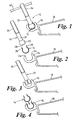
- a glazing component connector 10 comprising a first part 12 and a second part 14, which glazing component connector 10 is located in a C-shaped channel 16 of a first glazing component 18, in this case an eaves beam.
- the first part 12 comprises a head 20 and a shank 22.
- the head 20 consists of a truncated sphere, and from which extends the shank 22 which has a threaded portion 24.
- First part 12 is formed from a steel casting or the like.
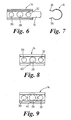
- Second part 14 is a locking clip which comprises an elongate member, generally C-shaped in cross section, from the open part of which C-shape extend two diverging feet 26. Approximately centrally located in the C-shaped part of the locking clip 14 are three holes 28, 30, 32 (see figures 6-10 ). A tab 33 is provided at one end of the locking clip 14. The locking clip 14 is pressed from sprung steel.
- First glazing component 18 can be a generally standard component except that it provides the C-shaped channel 16 extending from end-to-end for approximately 270°.
- Channel 16 has open ends 34.
- First glazing component 18 is a plastics extrusion.
- Channel 16 extends longitudinally along the length of first glazing component of 18 and the open ends 34 form a longitudinal opening in the C-shaped channel 16.
- the head 20 of first part 12 can pass into channel 16 of the first glazing component 18 through the open ends 34 of channel 16.
- locking clip 14 can also pass into channel 16 of the first glazing component 18 through the open ends 34 of channel 16.
- its normal diameter is greater than the spacing between the open ends 34, but it can be squeezed by using feet 26 to fit in channel 16.
- the external diameter of head 20 is approximately 0.5 mm smaller than the internal diameter of the C-shaped channel 16 and the glazing clip thickness is just less than 0.5 mm.
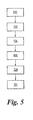
- step 100 the first glazing component 18 having a C-shaped channel 16 is provided.
- step 102 a glazing component connector 10 is provided.
- step 104 head 20 of first part 12 is inserted into C-shaped channel 16 through the longitudinal opening therein.
- Tab 33 can aid the insertion of the head 20, acting as a guide.
- step 106 the locking clip 14 is slid axially into the gap between the outside of head 20 and the inside of the C-shaped channel 16.
- the position desired for the glazing component connector 10 may be spaced significantly from either end of the glazing component 18, in which case (or otherwise) both the first and second parts 12, 14 can be inserted into the longitudinal gap of C-shaped channel 16, and then the glazing clip 14 can be slid axially (relative to the longitudinal axis of the C-shaped channel 16) over the head 20 of first part 12.
- step 106 instead the locking clip 14 can be inserted into C-shaped channel 16 first and then the head 20 of first past 12 can be slid axially into glazing clip 14.
- step 108 the shank 22 of first part 12 is located at the desired angle and a grub screw 36 ( Figure 11 ) is inserted through the base of C-shaped channel 16 to engage with a flat 38 ( Figure 2 ) of head 20.
- Figure 11 of the drawings that follow illustrates the range of angles the first part 12 can adopt in the C-shaped channel 16, over a range of 41°.
- the angle of the first glazing component relative to the second glazing component can be varied by pivotal movement of the connector.
- the centre of rotation of the pivoting action is within head 20.
- a second glazing component 40 such as in this case a hip rafter, is connected to first glazing component 18 using the shank 22 of first part 12 typically this will involve passing the shank to 22 into a hole in the second glazing component 40 and using a nut (not shown) to secure the second glazing component 40 in place.
- first part 12 is bolted to second glazing component 40 before being connected to first glazing component.
- the shank can tap into a port.
- FIGS 6-9 show various embodiments of locking clip 14.
- the glazing clip 14 does not include the diverging feet 26.
- the edge of the C-shaped includes a shaped portion 42 for receiving a part of the shank 22, helping to locate the shank 22 in place and stop it from moving unhelpfully when the second glazing component 40 is being located.
- FIG. 9 of the drawings that follow there is shown a third embodiment of a glazing clip 14, the end view of which is similar to figure 9 .
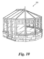
- a conservatory structure 100 comprising a plurality of glazing components connected using the glazing component connector described herein.
- preferred embodiments of the present invention provide a glazing component connector that is simple to use, reliable and robust yet flexible in its applications.
- the glazing component connector 10 is not limited to eaves beams and can be used for, for instance, hips, valleys and wall plates.
Landscapes
- Engineering & Computer Science (AREA)
- Architecture (AREA)
- Physics & Mathematics (AREA)
- Electromagnetism (AREA)
- Civil Engineering (AREA)
- Structural Engineering (AREA)
- Joining Of Building Structures In Genera (AREA)
- Joining Of Glass To Other Materials (AREA)
- Securing Of Glass Panes Or The Like (AREA)
- Insertion Pins And Rivets (AREA)
- Connection Of Plates (AREA)
Claims (18)
- Verglasungsbauteilverbinder (10), umfassend einen ersten Teil (12) und einen zweiten Teil (14), der erste Teil einen Kopf (20) für die Aufnahme durch eine Ergänzungsnut (16) eines ersten Verglasungsbauteils (18) umfassend, wobei sich von dem Kopf ein Schaft (22) zum Ermöglichen von Verbindung mit einem weiteren Verglasungsbauteil erstreckt, dadurch gekennzeichnet, dass der zweite Teil eine Verriegelungsklammer (14) zum Anordnen um den Kopf umfasst, wodurch der erste Teil in der Nut gesichert wird.
- Verglasungsbauteilverbinder (10) nach Anspruch 1, wobei die Verriegelungsklammer (14) generell C-förmig ist.
- Verglasungsbauteilverbinder (10) nach Anspruch 2, wobei die Enden der C-förmigen Verriegelungsklammer (14) auseinanderlaufende Füße (26) umfassen.
- Verglasungsbauteilverbinder (10) nach einem der vorhergehenden Ansprüche, wobei die Verriegelungsklammer (14) wenigstens eine durchgehende Bohrung (28, 30, 32) enthält.
- Verglasungsbauteilverbinder (10) nach Anspruch 4, wobei die Bohrung (28, 30, 32) geeignet ist, um einen Gewindestift mit Schlitz zum Sichern des ersten Teils (12) in der Position aufzunehmen.
- Verglasungsbauteilverbinder (10) nach Anspruch 4 oder 5, wobei die Bohrung (28, 30, 32) gegenüberliegend dem offenen Teil der C-förmigen Klammer (14) ist.
- Verglasungsbauteilverbinder (10) nach Anspruch 4, wobei die Klammer drei durchgehende Bohrungen (28, 30, 32) enthält.
- Verglasungsbauteilverbinder (10) nach einem der vorhergehenden Ansprüche, wobei die Verriegelungsklammer (14) einen Formteil zum Aufnehmen des Schaftes des ersten Teils (12) umfasst.
- Verglasungsbauteilverbinder (10) nach einem der vorhergehenden Ansprüche, wobei die Verriegelungsklammer (14) eine Führungsnase (33) enthält, die sich von dieser erstreckt.
- Verglasungsbauteilverbinder (10) nach einem der vorhergehenden Ansprüche, wobei der Kopf (20) eine angeschnittene Kugel umfasst.
- Verglasungsbauteilverbinder (10) nach einem der vorhergehenden Ansprüche, wobei der Schaft (22) ein Außengewinde umfasst.
- Anordnung, umfassend ein erstes Verglasungsbauteil und ein zweites Verglasungsbauteil, wobei das erste Verglasungsbauteil (18) mit dem zweiten Verglasungsbauteil (40) verbunden ist, das erste Verglasungsbauteil eine Nut (16) und einen Verglasungsbauteilverbinder (10) nach einem der vorhergehenden Ansprüche 1 bis 11 umfasst, wobei der Kopf (20) in die Nut passt und die Verriegelungsklammer (14) zwischen die Außenseite des Kopfes und die Innenseite der Nut passt und das zweite Verglasungsbauteil durch den ersten Teil des Verglasungsbauteilverbinders mit dem ersten Verglasungsbauteil verbunden ist.
- Anordnung nach Anspruch 12, wobei die Nut (16) eine Längsnut ist.
- Anordnung nach Anspruch 12 oder 13, wobei die Nut (16) generell C-förmig ist.
- Anordnung nach einem der Ansprüche 12 bis 14, wobei das erste Verglasungsbauteil ein Bauteil umfasst, das ausgewählt ist aus einem von einem Dachbalken, einem Walmsparren, einer Wandplatte und einer Dachkehle.
- Struktur, umfassend ein erstes Verglasungsbauteil (12), verbunden mit einem zweiten Verglasungsbauteil (14) in einer Weise nach einem der Ansprüche 12 bis 15.
- Struktur nach Anspruch 16, wobei die Struktur eine Wintergartenstruktur umfasst.
- Verfahren zum Verbinden eines ersten Verglasungsbauteils (18) mit einem zweiten Verglasungsbauteil (14), das erste Verglasungsbauteil eine Nut (16) umfassend, wobei das Verfahren die folgenden Schritte umfasst: Bereitstellen eines Verglasungsbauteilverbinders (10) nach einem der Ansprüche 1 bis 11, Einfügen von einem von dem ersten Teil (12) und dem zweiten Teil (14) in die Nut des ersten Verglasungsbauteils, Einfügen des anderen von dem ersten Teil und dem zweiten Teil in die Nut des ersten Verglasungsbauteils und Verbinden des zweiten Verglasungsbauteils mit dem ersten Verglasungsbauteil.
Applications Claiming Priority (2)
| Application Number | Priority Date | Filing Date | Title |
|---|---|---|---|
| GBGB0401326.4A GB0401326D0 (en) | 2004-01-22 | 2004-01-22 | Improvements in and relating to glazing component connection |
| PCT/GB2005/000197 WO2005070193A1 (en) | 2004-01-22 | 2005-01-21 | Glazing component connection and method |
Publications (2)
| Publication Number | Publication Date |
|---|---|
| EP1711047A1 EP1711047A1 (de) | 2006-10-18 |
| EP1711047B1 true EP1711047B1 (de) | 2008-05-21 |
Family
ID=31971231
Family Applications (1)
| Application Number | Title | Priority Date | Filing Date |
|---|---|---|---|
| EP05701960A Expired - Lifetime EP1711047B1 (de) | 2004-01-22 | 2005-01-21 | Vorrichtung und verfahren zur verbindung von verglasungselementen |
Country Status (6)
| Country | Link |
|---|---|
| US (1) | US20080236067A1 (de) |
| EP (1) | EP1711047B1 (de) |
| AT (1) | ATE395820T1 (de) |
| DE (1) | DE602005006975D1 (de) |
| GB (1) | GB0401326D0 (de) |
| WO (1) | WO2005070193A1 (de) |
Families Citing this family (1)
| Publication number | Priority date | Publication date | Assignee | Title |
|---|---|---|---|---|
| ITPG20050021A1 (it) * | 2005-04-13 | 2006-10-14 | Doriano Lilli | Supporto per sostegno di vetri, pannelli, marmo o altro con appoggio puntuale e snodo sferico |
Family Cites Families (6)
| Publication number | Priority date | Publication date | Assignee | Title |
|---|---|---|---|---|
| US2922670A (en) * | 1958-03-27 | 1960-01-26 | Superior Ball Joint Corp | Ball joint |
| DE1525283A1 (de) * | 1967-03-15 | 1969-09-18 | Schmidt Gmbh Karl | Kugelgelenk |
| NL1000698C2 (nl) * | 1995-06-29 | 1996-12-31 | Karel Jan Vollers | Bevestigingsinrichting voor het aan een gebouw bevestigen van gevel panelen, en gebouw voorzien van met die bevestigingsinrichting bevestig de gevelpanelen. |
| GB2378478B (en) * | 2001-08-04 | 2004-12-22 | Dennis Anthony Jones | Glazing bar mountings |
| EP1283311A3 (de) * | 2001-08-01 | 2004-02-11 | Aspect Management Ltd | Wintergartenstrukturen |
| DE20315778U1 (de) * | 2003-10-14 | 2003-12-11 | Böllhoff GmbH | Entkoppelnde Verbindungsanordnung mit Federklammer |
-
2004
- 2004-01-22 GB GBGB0401326.4A patent/GB0401326D0/en not_active Ceased
-
2005
- 2005-01-21 WO PCT/GB2005/000197 patent/WO2005070193A1/en not_active Ceased
- 2005-01-21 DE DE602005006975T patent/DE602005006975D1/de not_active Expired - Fee Related
- 2005-01-21 US US10/597,340 patent/US20080236067A1/en not_active Abandoned
- 2005-01-21 EP EP05701960A patent/EP1711047B1/de not_active Expired - Lifetime
- 2005-01-21 AT AT05701960T patent/ATE395820T1/de not_active IP Right Cessation
Also Published As
| Publication number | Publication date |
|---|---|
| DE602005006975D1 (de) | 2008-07-03 |
| US20080236067A1 (en) | 2008-10-02 |
| WO2005070193A1 (en) | 2005-08-04 |
| GB0401326D0 (en) | 2004-02-25 |
| EP1711047A1 (de) | 2006-10-18 |
| ATE395820T1 (de) | 2008-06-15 |
Similar Documents
| Publication | Publication Date | Title |
|---|---|---|
| US8235623B2 (en) | Pipe and tubing connector | |
| AU2021239839B2 (en) | Mounting device for a metal roof | |
| US20120272607A1 (en) | Building frame | |
| EP1697644B1 (de) | Vorrichtung zum verbinden eines trägerteiles mit einem anbauteil | |
| EP0709580B1 (de) | Verbindungselemente für Profilstangen mit T-förmigen Nuten | |
| US10047775B2 (en) | Attachment element | |
| EP1293685A2 (de) | Abstandshalter für die Befestigung eines Gegenstandes an einer eine Dämmschicht aufweisenden Wand | |
| DE20015528U1 (de) | Abhängelement | |
| US5297886A (en) | Connector bracket | |
| RU2434104C2 (ru) | Усовершенствованное соединение главных т-образных несущих прогонов | |
| DE10123924A1 (de) | Rohrschelle, insbesondere Rohrkupplung | |
| EP2256432A2 (de) | Ständer für rechteckige Solarmodule | |
| CN100564713C (zh) | 梁连接装置 | |
| EP2093434B1 (de) | Knotenverbinder | |
| US20080236067A1 (en) | Glazing Component Connection and Method | |
| US9482267B1 (en) | Omni-directional connection assembly | |
| GB0221137D0 (en) | A truss system | |
| PL212198B1 (pl) | Przyrząd do łączenia końców prętów | |
| EP3974667A1 (de) | Stockschraube sowie befestigungssystem mit dieser stockschraube | |
| WO2019084080A1 (en) | CONNECTION FITTINGS FOR A TRANSPORTABLE SHELTER | |
| GB2352490A (en) | An end-to-end connector for scaffolding poles | |
| US20020172551A1 (en) | Tube connector | |
| PL188790B1 (pl) | Sposób łączenia elementów metalowych za pomocą łącznika śrubowego | |
| DE102021118936A1 (de) | Stockschraube sowie Befestigungssystem mit dieser Stockschraube | |
| CN219604739U (zh) | 可调节的面板安装结构 |
Legal Events
| Date | Code | Title | Description |
|---|---|---|---|
| PUAI | Public reference made under article 153(3) epc to a published international application that has entered the european phase |
Free format text: ORIGINAL CODE: 0009012 |
|
| 17P | Request for examination filed |
Effective date: 20060815 |
|
| AK | Designated contracting states |
Kind code of ref document: A1 Designated state(s): AT BE BG CH CY CZ DE DK EE ES FI FR GB GR HU IE IS IT LI LT LU MC NL PL PT RO SE SI SK TR |
|
| 17Q | First examination report despatched |
Effective date: 20061129 |
|
| DAX | Request for extension of the european patent (deleted) | ||
| GRAP | Despatch of communication of intention to grant a patent |
Free format text: ORIGINAL CODE: EPIDOSNIGR1 |
|
| GRAS | Grant fee paid |
Free format text: ORIGINAL CODE: EPIDOSNIGR3 |
|
| GRAA | (expected) grant |
Free format text: ORIGINAL CODE: 0009210 |
|
| AK | Designated contracting states |
Kind code of ref document: B1 Designated state(s): AT BE BG CH CY CZ DE DK EE ES FI FR GB GR HU IE IS IT LI LT LU MC NL PL PT RO SE SI SK TR |
|
| REG | Reference to a national code |
Ref country code: GB Ref legal event code: FG4D |
|
| REG | Reference to a national code |
Ref country code: CH Ref legal event code: EP |
|
| REF | Corresponds to: |
Ref document number: 602005006975 Country of ref document: DE Date of ref document: 20080703 Kind code of ref document: P |
|
| REG | Reference to a national code |
Ref country code: IE Ref legal event code: FG4D |
|
| PG25 | Lapsed in a contracting state [announced via postgrant information from national office to epo] |
Ref country code: SI Free format text: LAPSE BECAUSE OF FAILURE TO SUBMIT A TRANSLATION OF THE DESCRIPTION OR TO PAY THE FEE WITHIN THE PRESCRIBED TIME-LIMIT Effective date: 20080521 |
|
| PG25 | Lapsed in a contracting state [announced via postgrant information from national office to epo] |
Ref country code: FI Free format text: LAPSE BECAUSE OF FAILURE TO SUBMIT A TRANSLATION OF THE DESCRIPTION OR TO PAY THE FEE WITHIN THE PRESCRIBED TIME-LIMIT Effective date: 20080521 Ref country code: ES Free format text: LAPSE BECAUSE OF FAILURE TO SUBMIT A TRANSLATION OF THE DESCRIPTION OR TO PAY THE FEE WITHIN THE PRESCRIBED TIME-LIMIT Effective date: 20080901 |
|
| NLV1 | Nl: lapsed or annulled due to failure to fulfill the requirements of art. 29p and 29m of the patents act | ||
| PG25 | Lapsed in a contracting state [announced via postgrant information from national office to epo] |
Ref country code: PL Free format text: LAPSE BECAUSE OF FAILURE TO SUBMIT A TRANSLATION OF THE DESCRIPTION OR TO PAY THE FEE WITHIN THE PRESCRIBED TIME-LIMIT Effective date: 20080521 Ref country code: NL Free format text: LAPSE BECAUSE OF FAILURE TO SUBMIT A TRANSLATION OF THE DESCRIPTION OR TO PAY THE FEE WITHIN THE PRESCRIBED TIME-LIMIT Effective date: 20080521 Ref country code: AT Free format text: LAPSE BECAUSE OF FAILURE TO SUBMIT A TRANSLATION OF THE DESCRIPTION OR TO PAY THE FEE WITHIN THE PRESCRIBED TIME-LIMIT Effective date: 20080521 |
|
| PG25 | Lapsed in a contracting state [announced via postgrant information from national office to epo] |
Ref country code: IS Free format text: LAPSE BECAUSE OF FAILURE TO SUBMIT A TRANSLATION OF THE DESCRIPTION OR TO PAY THE FEE WITHIN THE PRESCRIBED TIME-LIMIT Effective date: 20080921 |
|
| PG25 | Lapsed in a contracting state [announced via postgrant information from national office to epo] |
Ref country code: SE Free format text: LAPSE BECAUSE OF FAILURE TO SUBMIT A TRANSLATION OF THE DESCRIPTION OR TO PAY THE FEE WITHIN THE PRESCRIBED TIME-LIMIT Effective date: 20080821 Ref country code: CZ Free format text: LAPSE BECAUSE OF FAILURE TO SUBMIT A TRANSLATION OF THE DESCRIPTION OR TO PAY THE FEE WITHIN THE PRESCRIBED TIME-LIMIT Effective date: 20080521 Ref country code: LT Free format text: LAPSE BECAUSE OF FAILURE TO SUBMIT A TRANSLATION OF THE DESCRIPTION OR TO PAY THE FEE WITHIN THE PRESCRIBED TIME-LIMIT Effective date: 20080521 Ref country code: DK Free format text: LAPSE BECAUSE OF FAILURE TO SUBMIT A TRANSLATION OF THE DESCRIPTION OR TO PAY THE FEE WITHIN THE PRESCRIBED TIME-LIMIT Effective date: 20080521 |
|
| PG25 | Lapsed in a contracting state [announced via postgrant information from national office to epo] |
Ref country code: SK Free format text: LAPSE BECAUSE OF FAILURE TO SUBMIT A TRANSLATION OF THE DESCRIPTION OR TO PAY THE FEE WITHIN THE PRESCRIBED TIME-LIMIT Effective date: 20080521 Ref country code: PT Free format text: LAPSE BECAUSE OF FAILURE TO SUBMIT A TRANSLATION OF THE DESCRIPTION OR TO PAY THE FEE WITHIN THE PRESCRIBED TIME-LIMIT Effective date: 20081021 Ref country code: RO Free format text: LAPSE BECAUSE OF FAILURE TO SUBMIT A TRANSLATION OF THE DESCRIPTION OR TO PAY THE FEE WITHIN THE PRESCRIBED TIME-LIMIT Effective date: 20080521 Ref country code: BE Free format text: LAPSE BECAUSE OF FAILURE TO SUBMIT A TRANSLATION OF THE DESCRIPTION OR TO PAY THE FEE WITHIN THE PRESCRIBED TIME-LIMIT Effective date: 20080521 |
|
| PLBE | No opposition filed within time limit |
Free format text: ORIGINAL CODE: 0009261 |
|
| STAA | Information on the status of an ep patent application or granted ep patent |
Free format text: STATUS: NO OPPOSITION FILED WITHIN TIME LIMIT |
|
| 26N | No opposition filed |
Effective date: 20090224 |
|
| PG25 | Lapsed in a contracting state [announced via postgrant information from national office to epo] |
Ref country code: BG Free format text: LAPSE BECAUSE OF FAILURE TO SUBMIT A TRANSLATION OF THE DESCRIPTION OR TO PAY THE FEE WITHIN THE PRESCRIBED TIME-LIMIT Effective date: 20080821 Ref country code: EE Free format text: LAPSE BECAUSE OF FAILURE TO SUBMIT A TRANSLATION OF THE DESCRIPTION OR TO PAY THE FEE WITHIN THE PRESCRIBED TIME-LIMIT Effective date: 20080521 |
|
| PGFP | Annual fee paid to national office [announced via postgrant information from national office to epo] |
Ref country code: GB Payment date: 20090202 Year of fee payment: 5 |
|
| PG25 | Lapsed in a contracting state [announced via postgrant information from national office to epo] |
Ref country code: MC Free format text: LAPSE BECAUSE OF NON-PAYMENT OF DUE FEES Effective date: 20090131 Ref country code: IT Free format text: LAPSE BECAUSE OF FAILURE TO SUBMIT A TRANSLATION OF THE DESCRIPTION OR TO PAY THE FEE WITHIN THE PRESCRIBED TIME-LIMIT Effective date: 20080521 |
|
| REG | Reference to a national code |
Ref country code: CH Ref legal event code: PL |
|
| REG | Reference to a national code |
Ref country code: IE Ref legal event code: MM4A |
|
| PG25 | Lapsed in a contracting state [announced via postgrant information from national office to epo] |
Ref country code: DE Free format text: LAPSE BECAUSE OF NON-PAYMENT OF DUE FEES Effective date: 20090801 Ref country code: CH Free format text: LAPSE BECAUSE OF NON-PAYMENT OF DUE FEES Effective date: 20090131 Ref country code: LI Free format text: LAPSE BECAUSE OF NON-PAYMENT OF DUE FEES Effective date: 20090131 |
|
| REG | Reference to a national code |
Ref country code: FR Ref legal event code: ST Effective date: 20091030 |
|
| PG25 | Lapsed in a contracting state [announced via postgrant information from national office to epo] |
Ref country code: IE Free format text: LAPSE BECAUSE OF NON-PAYMENT OF DUE FEES Effective date: 20090121 |
|
| PG25 | Lapsed in a contracting state [announced via postgrant information from national office to epo] |
Ref country code: FR Free format text: LAPSE BECAUSE OF NON-PAYMENT OF DUE FEES Effective date: 20090202 |
|
| GBPC | Gb: european patent ceased through non-payment of renewal fee |
Effective date: 20100121 |
|
| PG25 | Lapsed in a contracting state [announced via postgrant information from national office to epo] |
Ref country code: GR Free format text: LAPSE BECAUSE OF FAILURE TO SUBMIT A TRANSLATION OF THE DESCRIPTION OR TO PAY THE FEE WITHIN THE PRESCRIBED TIME-LIMIT Effective date: 20080822 |
|
| PG25 | Lapsed in a contracting state [announced via postgrant information from national office to epo] |
Ref country code: GB Free format text: LAPSE BECAUSE OF NON-PAYMENT OF DUE FEES Effective date: 20100121 |
|
| PG25 | Lapsed in a contracting state [announced via postgrant information from national office to epo] |
Ref country code: LU Free format text: LAPSE BECAUSE OF NON-PAYMENT OF DUE FEES Effective date: 20090121 |
|
| PG25 | Lapsed in a contracting state [announced via postgrant information from national office to epo] |
Ref country code: HU Free format text: LAPSE BECAUSE OF FAILURE TO SUBMIT A TRANSLATION OF THE DESCRIPTION OR TO PAY THE FEE WITHIN THE PRESCRIBED TIME-LIMIT Effective date: 20081122 |
|
| PG25 | Lapsed in a contracting state [announced via postgrant information from national office to epo] |
Ref country code: TR Free format text: LAPSE BECAUSE OF FAILURE TO SUBMIT A TRANSLATION OF THE DESCRIPTION OR TO PAY THE FEE WITHIN THE PRESCRIBED TIME-LIMIT Effective date: 20080521 |
|
| PG25 | Lapsed in a contracting state [announced via postgrant information from national office to epo] |
Ref country code: CY Free format text: LAPSE BECAUSE OF FAILURE TO SUBMIT A TRANSLATION OF THE DESCRIPTION OR TO PAY THE FEE WITHIN THE PRESCRIBED TIME-LIMIT Effective date: 20080521 |