EP1710819A2 - Device for monitoring the closed state of two relatively moving parts - Google Patents
Device for monitoring the closed state of two relatively moving parts Download PDFInfo
- Publication number
- EP1710819A2 EP1710819A2 EP06006928A EP06006928A EP1710819A2 EP 1710819 A2 EP1710819 A2 EP 1710819A2 EP 06006928 A EP06006928 A EP 06006928A EP 06006928 A EP06006928 A EP 06006928A EP 1710819 A2 EP1710819 A2 EP 1710819A2
- Authority
- EP
- European Patent Office
- Prior art keywords
- sensor
- housing
- trigger
- trigger housing
- holder
- Prior art date
- Legal status (The legal status is an assumption and is not a legal conclusion. Google has not performed a legal analysis and makes no representation as to the accuracy of the status listed.)
- Granted
Links
Images

Classifications
-
- H—ELECTRICITY
- H01—ELECTRIC ELEMENTS
- H01H—ELECTRIC SWITCHES; RELAYS; SELECTORS; EMERGENCY PROTECTIVE DEVICES
- H01H9/00—Details of switching devices, not covered by groups H01H1/00 - H01H7/00
- H01H9/02—Bases, casings, or covers
- H01H9/0207—Adjustable mounting of casings
Definitions
- sensor and trigger housing 14, 17 may already be accommodated during the attachment of the holders 3 thereof - swung up - or subsequently be received and latched by the receivers 8 after the provisional attachment of the holders 3, FIG. 2 , after which the set switching distance can be tested. If necessary, then the sensor or trigger housing 14, 17 can be released again from the latch and swung up to perfect the adjustment until the desired result is achieved.
Abstract
Description
Die Erfindung begrifft eine Einrichtung zum Überwachen des geschlossenen Zustands von zwei relativ zueinander beweglichen Teilen gemäß dem Oberbegriff des Anspruchs 1.The invention relates to a device for monitoring the closed state of two relatively movable parts according to the preamble of
Für die Überwachung des geschlossenen Zustands von zwei relativ zueinander beweglichen Teilen, etwa einer Tür oder Klappe, die gegenüber einer feststehenden Wandung beweglich ist, oder von zwei gegeneinander beweglichen Türflügeln, wird üblicherweise an einem Teil ein Sensor befestigt, während am anderen Teil ein Auslöser hierfür angebracht wird. Da dies über Bohrungen geschieht und diese gewöhnlich nicht genügend genau gesetzt werden, kommt es häufig zu Problemen hinsichtlich der Einstellung des Schaltabstandes für den Auslöser.For monitoring the closed state of two relatively movable parts, such as a door or flap, which is movable relative to a fixed wall, or of two mutually movable door wings, a sensor is usually attached to one part, while the other part a trigger for this is attached. Since this is done through holes and these are usually not set exactly enough, there are often problems with regard to the setting of the switching distance for the trigger.
Aufgabe der Erfindung ist es daher, eine Einrichtung nach dem Oberbegriff des Anspruchs 1 zu schaffen, die es ermöglicht, auch bei ungenau angebrachten Bohrungen den Schaltabstand korrekt einzustellen.The object of the invention is therefore to provide a device according to the preamble of
Diese Aufgabe wird entsprechend den Merkmalen des Anspruchs 1 gelöst.This object is achieved according to the features of
Dadurch, daß bei einer Einrichtung zum Überwachen des geschlossenen Zustands von zwei relativ zueinander beweglichen Teilen, die einen ein Sensorgehäuse und ein Schaltelement umfassenden Sensor und einen ein Auslösergehäuse umfassenden Auslöser hierfür aufweist, die jeweils an einem der beiden relativ zueinander beweglichen Teile montierbar sind, vorgesehen ist, daß das Sensor- und/oder Auslösergehäuse über gegebenenfalls jeweils eine Halterung montierbar ist, die eine eine Bodenplatte aufweisende Fassung für das Sensor- und/oder Auslösergehäuse bildet, wobei die Bodenplatte zwei zueinander beabstandete und drehbar darin aufgenommene Einsätze aufweist, die jeweils mit einem Langloch für den Durchtritt einer Befestigungsschraube versehen sind, ist es möglich, die wenigstens eine Halterung durch Verdrehen von deren Einsätzen in eine Position zu bringen, die dem korrekten Schaltabstand entspricht.Characterized in that in a device for monitoring the closed state of two relatively movable parts, comprising a sensor housing and a switching element comprehensive sensor and a trigger housing comprehensive trigger this, which are each mounted on one of the two relatively movable parts provided is that the sensor and / or trigger housing can be mounted on optionally a respective holder which forms a base plate having socket for the sensor and / or trigger housing, the bottom plate has two spaced-apart and rotatably received therein inserts, each with a slot for the passage of a fastening screw are provided, it is possible to bring the at least one holder by turning their inserts in a position corresponding to the correct operating distance.
Hierbei kann das Verdrehen der Einsätze durch einfaches Einführen eines entsprechenden Werkzeugs in das jeweilige Langloch des Einsatzes und Verdrehen des Werkzeugs vorgenommen werden, wonach in der endgültigen Position die in das jeweilige Langloch eingesetzte Befestigungsschraube fest arigezogen wird. Dies ermöglicht somit eine einfache und schnelle Montage.Here, the rotation of the inserts by simply inserting a corresponding tool in the respective slot of the insert and twisting of the tool can be made, after which the fastening screw inserted into the respective slot is firmly arigezogen in the final position. This allows a simple and quick installation.
Dabei ist es zudem zweckmäßig, wenn das Langloch vertieft in dem jeweiligen Einsatz angeordnet ist, wodurch der Schraubenkopf im Einsatz aufgenommen ist und sich auf dem das Langloch umgebenden Bund abstützt.It is also expedient if the slot is recessed in the respective insert is arranged, whereby the screw head is received in use and is supported on the surrounding the slot federal government.
Ferner ist es vorteilhaft, wenn an der Bodenplatte an einem Ende eine Aufnahme für das Sensor- bzw. Auslösergehäuse schwenkbar angeordnet ist. Hierdurch kann das jeweilige Gehäuse zwischen der montierten Position und einer hochgeklappten Position, in der die Befestigungsschrauben in den Einsätzen zugänglich sind, verschwenkt werden, um eine Überprüfung des Schaltabstandes und dessen Korrektur einfach durch Ausprobieren bewerkstelligen zu können.Further, it is advantageous if a receptacle for the sensor or trigger housing is pivotally mounted on the bottom plate at one end. In this way, the respective housing between the mounted position and a folded-up position in which the fastening screws are accessible in the inserts, be pivoted to a review of the switching distance and its correction can be accomplished simply by trial and error.
Die Gehäuse können auch mittels lösbarer Rastelemente an der Halterung gehalten werden, wobei es bevorzugt ist, wenn dies nur an einer Seite geschieht, während an der anderen Seite die schwenkbare Aufnahme angeordnet ist.The housing can also be held by means of releasable locking elements on the holder, it being preferred, if this happens only on one side, while on the other side, the pivotable receptacle is arranged.
Vorteilhaft sind auch gleich große Sensor- und Auslösergehäuse, da dann gleiche Halterungen hierfür verwendet werden können.Also advantageous are the same sized sensor and shutter housing, since then the same brackets can be used for this purpose.
Weitere Ausgestaltungen der Erfindung sind der nachfolgenden Beschreibung und den Unteransprüchen zu entnehmen.Further embodiments of the invention are described in the following description and the dependent claims.
Die Erfindung wird nachstehend anhand eines in den beigefügten Abbildungen dargestellten Ausführungsbeispiels näher erläutert.The invention is explained below with reference to an embodiment shown in the accompanying drawings.
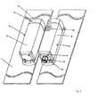
Fig. 1 und 2 zeigen eine Ausführungsform einer Einrichtung zum Überwachen des geschlossenen Zustands von zwei relativ zueinander beweglichen Teilen perspektivisch in zwei unterschiedlichen Montagezuständen.Figs. 1 and 2 show in perspective an embodiment of a device for monitoring the closed state of two relatively movable parts in two different states of assembly.
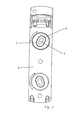
Fig. 3 zeigt schematisch in Draufsicht eine Halterung für die Einrichtung von Fig. 1, 2.FIG. 3 shows schematically in plan view a holder for the device of FIGS. 1, 2.
Die dargestellte Einrichtung zum Überwachen des geschlossenen Zustands von zwei relativ zueinander beweglichen, schematisch dargestellten Teilen 1, 2, etwa einer Tür gegenüber einer Wandung, umfaßt bei dem dargestellten Ausführungsbeispiel zwei Halterungen 3, die jeweils eine langgestreckte, rechteckige Bodenplatte 4 umfassen. Jede Halterung 3 nimmt zwei in Längsrichtung hiervon zueinander beabstandet angeordnete Einsätze 5 drehbar auf. Die Einsätze 5 sind beispielsweise eingeschnappt. Die Einsätze 5 weisen im dargestellten Ausführungsbeispiel jeweils eine längliche Vertiefung 6 auf, deren Boden mit einem Langloch 7 zum Durchtritt einer Befestigungsschraube versehen ist, die sich mit ihrem Kopf auf dem Boden der Vertiefung 6 abstützt und mit ihrem Kopf von der Vertiefung 6 aufgenommen wird.The illustrated device for monitoring the closed state of two relatively movable, schematically illustrated
Jede Halterung 3 weist an einem Ende der Bodenplatte 4 eine gegenüber dieser schwenkbare Aufnahme 8, die beim dargestellten Ausführungsbeispiel in Form einer rahmenartigen Kappe ausgebildet ist, auf. Die Bodenplatte 4 weist hierzu zwei Fortsätze 9 auf, in die eine Achse 10 eingesteckt ist. Die Aufnahme 8 weist entsprechende Fortsätze 11 auf, durch die sich die Achse 10 hindurch erstreckt.Each
Gegenüberliegend von der Aufnahme 7 befinden sich am anderen Ende der Bodenplatte 4 zwei Nasen oder als Rastnasen ausgebildete Rastelemente 12.Opposite of the
Die Einrichtung umfaßt ferner einen Sensor 13 mit einem Sensorgehäuse 14, das ein Sensorelement, beispielsweise einen Reedschalter, einen Näherungsschalter od.dgl., aufnimmt, das über ein Kabel, das über eine Kabeldurchführung 15 aus dem Sensorgehäuse 14 herausgeführt ist, mit einem Überwachungsschaltkreis bzw. -steuerung verbunden werden kann.The device further comprises a sensor 13 with a
Außerdem umfaßt die Einrichtung einen Auslöser 16 mit einem in einem Auslösergehäuse 17 untergebrachten Auslöseelement, etwa einen Magneten, eine Metallplatte, einen Tag (Transpoderelement) od.dgl.In addition, the device comprises a
Sensor- und Auslösergehäuse 14, 17 sind von gleicher Gestalt und Größe bei quadratischem Querschnitt und besitzen an einem Ende einen im Querschnitt verjüngten Abschnitt zum Einstecken in die entsprechende Aufnahme 8 der Halterung 3. Nach Einstecken können sie mittels einer Schraube 18 an der Aufnahme 8 gesichert werden.Sensor and
An der gegenüberliegenden Stirnseite weisen Sensor- und Auslösergehäuse 14, 17 in den vier Eckbereichen jeweils eine Ausnehmung 19 zum Einstecken der Nasen bzw. Einrasten der Rastelemente 12 der Halterung 3 auf.On the opposite end side, the sensor and
Die Breite der Bodenplatte 4 und damit der Halterung 3 ist zweckmäßigerweise gleich derjenigen des Sensor- und des Auslösergehäuses 14, 17, so diese im montierten Zustand fluchten.The width of the
Zur Montage werden entsprechend den beiden relativ zueinander beweglichen Teilen 1, 2 jeweils zwei Bohrungen zur Aufnahme von zwei Befestigungsschrauben für jeweils eine der beiden benötigten Halterungen 3 angebracht und letztere mittels Befestigungsschrauben provisorisch befestigt. Danach werden Sensor- und Auslösergehäuse 14, 17 auf die Nasen 12 geschoben, wonach der so eingestellte Schaltabstand getestet werden kann. Bei Bedarf kann das Sensor- bzw. Auslösergehäuse 14, 17 wieder entnommen werden, wonach die Halterungen 3 mittels Verdrehen der Einsätze 5 relativ zueinander verstellt werden können, wobei dies wiederholt wird, bis das gewünschte Ergebnis erreicht ist. Am Ende werden die schwenkbar an den Halterungen 3 vorgesehenen Aufnahmen 8 auf die Enden von Sensor- und Auslösergehäuse 14, 17 geschwenkt und mittels der jeweiligen Schraube 18 gesichert. - Wenn Rastelemente 12 verwendet werden, können gegebenenfalls Sensor- und Auslösergehäuse 14, 17 bereits bei der Anbringung der Halterungen 3 hiervon - hochgeschwenkt - aufgenommen sein oder anschließend nach der provisorischer Anbringung der Halterungen 3 von den Aufnahmen 8 aufgenommen und eingerastet werden, Fig. 2, wonach der so eingestellte Schaltabstand getestet werden kann. Bei Bedarf kann dann das Sensor- bzw. Auslösergehäuse 14, 17 wieder aus der Verrastung gelöst und hochgeschwenkt werden, um die Justierung zu vervollkommnen, bis das gewünschte Ergebnis erreicht ist.For mounting according to the two relatively
Das Sensorgehäuse 14 kann ein Fenster 20 für eine Anzeigeeinrichtung aufweisen.The
Claims (8)
Applications Claiming Priority (1)
| Application Number | Priority Date | Filing Date | Title |
|---|---|---|---|
| DE200510015794 DE102005015794B4 (en) | 2005-04-06 | 2005-04-06 | Device for monitoring the closed state of two relatively movable parts |
Publications (3)
| Publication Number | Publication Date |
|---|---|
| EP1710819A2 true EP1710819A2 (en) | 2006-10-11 |
| EP1710819A3 EP1710819A3 (en) | 2007-11-14 |
| EP1710819B1 EP1710819B1 (en) | 2010-11-17 |
Family
ID=36579934
Family Applications (1)
| Application Number | Title | Priority Date | Filing Date |
|---|---|---|---|
| EP20060006928 Expired - Fee Related EP1710819B1 (en) | 2005-04-06 | 2006-03-31 | Device for monitoring the closed state of two relatively moving parts |
Country Status (2)
| Country | Link |
|---|---|
| EP (1) | EP1710819B1 (en) |
| DE (2) | DE102005015794B4 (en) |
Cited By (2)
| Publication number | Priority date | Publication date | Assignee | Title |
|---|---|---|---|---|
| ITVI20100055A1 (en) * | 2010-02-26 | 2011-08-27 | Pizzato Elettrica Srl | POSITION SWITCH |
| IT202000025354A1 (en) * | 2020-10-26 | 2022-04-26 | Pizzato Elettrica Srl | HANDLE ACTUATOR DEVICE FOR ACCESSES TO INDUSTRIAL MACHINERY OR INSTALLATIONS AND RELATED ASSEMBLY |
Citations (4)
| Publication number | Priority date | Publication date | Assignee | Title |
|---|---|---|---|---|
| DE3605067C1 (en) * | 1986-02-18 | 1987-07-09 | Schmersal K A Gmbh & Co | Non-contact-making magnetic switch (magnet-operated switch) |
| US4916265A (en) * | 1988-11-21 | 1990-04-10 | Gary D. Thomas | Adjustable mounting assembly for a limit switch |
| DE29822912U1 (en) * | 1998-12-23 | 2000-05-11 | Moeller Gmbh | Mounting adapter for fastening electrical devices |
| EP1063773A2 (en) * | 1999-06-23 | 2000-12-27 | K.A. SCHMERSAL GmbH & Co. | Safety sensor |
-
2005
- 2005-04-06 DE DE200510015794 patent/DE102005015794B4/en not_active Expired - Fee Related
-
2006
- 2006-03-31 EP EP20060006928 patent/EP1710819B1/en not_active Expired - Fee Related
- 2006-03-31 DE DE200650008309 patent/DE502006008309D1/en active Active
Patent Citations (4)
| Publication number | Priority date | Publication date | Assignee | Title |
|---|---|---|---|---|
| DE3605067C1 (en) * | 1986-02-18 | 1987-07-09 | Schmersal K A Gmbh & Co | Non-contact-making magnetic switch (magnet-operated switch) |
| US4916265A (en) * | 1988-11-21 | 1990-04-10 | Gary D. Thomas | Adjustable mounting assembly for a limit switch |
| DE29822912U1 (en) * | 1998-12-23 | 2000-05-11 | Moeller Gmbh | Mounting adapter for fastening electrical devices |
| EP1063773A2 (en) * | 1999-06-23 | 2000-12-27 | K.A. SCHMERSAL GmbH & Co. | Safety sensor |
Cited By (4)
| Publication number | Priority date | Publication date | Assignee | Title |
|---|---|---|---|---|
| ITVI20100055A1 (en) * | 2010-02-26 | 2011-08-27 | Pizzato Elettrica Srl | POSITION SWITCH |
| EP2362402A1 (en) * | 2010-02-26 | 2011-08-31 | Pizzato Elettrica S.r.l. | Proximity switch |
| IT202000025354A1 (en) * | 2020-10-26 | 2022-04-26 | Pizzato Elettrica Srl | HANDLE ACTUATOR DEVICE FOR ACCESSES TO INDUSTRIAL MACHINERY OR INSTALLATIONS AND RELATED ASSEMBLY |
| WO2022090887A1 (en) * | 2020-10-26 | 2022-05-05 | Pizzato Elettrica S.R.L. | Handle actuator device for access to industrial machines or plants and related assembly |
Also Published As
| Publication number | Publication date |
|---|---|
| DE102005015794B4 (en) | 2007-05-03 |
| EP1710819B1 (en) | 2010-11-17 |
| DE502006008309D1 (en) | 2010-12-30 |
| DE102005015794A1 (en) | 2006-10-12 |
| EP1710819A3 (en) | 2007-11-14 |
Similar Documents
| Publication | Publication Date | Title |
|---|---|---|
| DE10224757B3 (en) | Plug connector with secondary locking that locks during the plugging process | |
| DE10303002A1 (en) | Device for mounting a telescopic sight on a weapon | |
| EP2055867A1 (en) | Grip with fastening insert | |
| EP2875199B1 (en) | Guide for espagnolette bar | |
| EP2965843B1 (en) | Collet chuck and clamping means with quick change function | |
| EP2180121B1 (en) | Device for fixing the position of a bonnet | |
| DE2944862A1 (en) | DEVICE FOR ATTACHING AN ELECTRICAL DEVICE TO A BREAKTHROUGH OF A MOTOR VEHICLE PART | |
| EP1710819B1 (en) | Device for monitoring the closed state of two relatively moving parts | |
| DE2530199A1 (en) | BRACKET FOR FASTENING A DEVICE OF COMMUNICATION TECHNOLOGY | |
| EP3327240B1 (en) | Holding device for holding a sun protection device and holding system | |
| DE10147023A1 (en) | Fastening device for sensors and sensor | |
| DE3619584C2 (en) | ||
| WO2018050651A1 (en) | Casing for a control unit and covering hood for the casing | |
| EP0180146A2 (en) | Punching machine | |
| DE3610613A1 (en) | Measuring instrument housing | |
| EP1985792A2 (en) | Belt coiler for a roller shutter | |
| DE102018114585A1 (en) | Drawer and method for mounting a rear wall on a side frame of a drawer | |
| DE202009004949U1 (en) | air nozzle | |
| EP1163083A1 (en) | Angle grinder | |
| DE102007004018A1 (en) | Attachment for box shaped receiving holder for devices, has passage opening that is arranged in side wall of receiving holder for pivotable lever | |
| DE102007044057A1 (en) | Sliding door mounting device for use during e.g. painting, in manufacturing process of motor vehicle, has adapters, which are not connected with each other, and upper units arranged at one adapter and lower units arranged at other adapter | |
| DE102009012355A1 (en) | System for attaching frame of door and gate to base body, has receiving element affixed or fastened to frame, and adapter element fastened to receiving element or to base body in form-fit and force fit manner | |
| DE2905317A1 (en) | CONTROL PANEL DEVICE WITH A FASTENING ELEMENT | |
| DE202015002795U1 (en) | Locking device of a plug-in module | |
| DE202014102454U1 (en) | Device for attaching a toilet seat to a toilet bowl |
Legal Events
| Date | Code | Title | Description |
|---|---|---|---|
| PUAI | Public reference made under article 153(3) epc to a published international application that has entered the european phase |
Free format text: ORIGINAL CODE: 0009012 |
|
| AK | Designated contracting states |
Kind code of ref document: A2 Designated state(s): AT BE BG CH CY CZ DE DK EE ES FI FR GB GR HU IE IS IT LI LT LU LV MC NL PL PT RO SE SI SK TR |
|
| AX | Request for extension of the european patent |
Extension state: AL BA HR MK YU |
|
| PUAL | Search report despatched |
Free format text: ORIGINAL CODE: 0009013 |
|
| AK | Designated contracting states |
Kind code of ref document: A3 Designated state(s): AT BE BG CH CY CZ DE DK EE ES FI FR GB GR HU IE IS IT LI LT LU LV MC NL PL PT RO SE SI SK TR |
|
| AX | Request for extension of the european patent |
Extension state: AL BA HR MK YU |
|
| 17P | Request for examination filed |
Effective date: 20080311 |
|
| AKX | Designation fees paid |
Designated state(s): DE FR GB IT |
|
| GRAP | Despatch of communication of intention to grant a patent |
Free format text: ORIGINAL CODE: EPIDOSNIGR1 |
|
| GRAS | Grant fee paid |
Free format text: ORIGINAL CODE: EPIDOSNIGR3 |
|
| GRAA | (expected) grant |
Free format text: ORIGINAL CODE: 0009210 |
|
| AK | Designated contracting states |
Kind code of ref document: B1 Designated state(s): DE FR GB IT |
|
| REG | Reference to a national code |
Ref country code: GB Ref legal event code: FG4D Free format text: NOT ENGLISH |
|
| REF | Corresponds to: |
Ref document number: 502006008309 Country of ref document: DE Date of ref document: 20101230 Kind code of ref document: P |
|
| PLBE | No opposition filed within time limit |
Free format text: ORIGINAL CODE: 0009261 |
|
| STAA | Information on the status of an ep patent application or granted ep patent |
Free format text: STATUS: NO OPPOSITION FILED WITHIN TIME LIMIT |
|
| 26N | No opposition filed |
Effective date: 20110818 |
|
| REG | Reference to a national code |
Ref country code: DE Ref legal event code: R097 Ref document number: 502006008309 Country of ref document: DE Effective date: 20110818 |
|
| REG | Reference to a national code |
Ref country code: FR Ref legal event code: PLFP Year of fee payment: 10 |
|
| PGFP | Annual fee paid to national office [announced via postgrant information from national office to epo] |
Ref country code: IT Payment date: 20150325 Year of fee payment: 10 |
|
| PGFP | Annual fee paid to national office [announced via postgrant information from national office to epo] |
Ref country code: FR Payment date: 20150319 Year of fee payment: 10 Ref country code: GB Payment date: 20150319 Year of fee payment: 10 |
|
| PGFP | Annual fee paid to national office [announced via postgrant information from national office to epo] |
Ref country code: DE Payment date: 20150528 Year of fee payment: 10 |
|
| REG | Reference to a national code |
Ref country code: DE Ref legal event code: R119 Ref document number: 502006008309 Country of ref document: DE |
|
| GBPC | Gb: european patent ceased through non-payment of renewal fee |
Effective date: 20160331 |
|
| REG | Reference to a national code |
Ref country code: FR Ref legal event code: ST Effective date: 20161130 |
|
| PG25 | Lapsed in a contracting state [announced via postgrant information from national office to epo] |
Ref country code: DE Free format text: LAPSE BECAUSE OF NON-PAYMENT OF DUE FEES Effective date: 20161001 Ref country code: FR Free format text: LAPSE BECAUSE OF NON-PAYMENT OF DUE FEES Effective date: 20160331 Ref country code: GB Free format text: LAPSE BECAUSE OF NON-PAYMENT OF DUE FEES Effective date: 20160331 |
|
| PG25 | Lapsed in a contracting state [announced via postgrant information from national office to epo] |
Ref country code: IT Free format text: LAPSE BECAUSE OF NON-PAYMENT OF DUE FEES Effective date: 20160331 |