EP1710552B1 - Procede de mesure de fibre optique multimode - Google Patents
Procede de mesure de fibre optique multimode Download PDFInfo
- Publication number
- EP1710552B1 EP1710552B1 EP05709347.8A EP05709347A EP1710552B1 EP 1710552 B1 EP1710552 B1 EP 1710552B1 EP 05709347 A EP05709347 A EP 05709347A EP 1710552 B1 EP1710552 B1 EP 1710552B1
- Authority
- EP
- European Patent Office
- Prior art keywords
- measurement
- dmd
- optical fiber
- temperature
- change
- Prior art date
- Legal status (The legal status is an assumption and is not a legal conclusion. Google has not performed a legal analysis and makes no representation as to the accuracy of the status listed.)
- Expired - Lifetime
Links
Images


Classifications
-
- G—PHYSICS
- G01—MEASURING; TESTING
- G01M—TESTING STATIC OR DYNAMIC BALANCE OF MACHINES OR STRUCTURES; TESTING OF STRUCTURES OR APPARATUS, NOT OTHERWISE PROVIDED FOR
- G01M99/00—Subject matter not provided for in other groups of this subclass
- G01M99/002—Thermal testing
-
- G—PHYSICS
- G01—MEASURING; TESTING
- G01M—TESTING STATIC OR DYNAMIC BALANCE OF MACHINES OR STRUCTURES; TESTING OF STRUCTURES OR APPARATUS, NOT OTHERWISE PROVIDED FOR
- G01M11/00—Testing of optical apparatus; Testing structures by optical methods not otherwise provided for
- G01M11/30—Testing of optical devices, constituted by fibre optics or optical waveguides
-
- G—PHYSICS
- G01—MEASURING; TESTING
- G01K—MEASURING TEMPERATURE; MEASURING QUANTITY OF HEAT; THERMALLY-SENSITIVE ELEMENTS NOT OTHERWISE PROVIDED FOR
- G01K11/00—Measuring temperature based upon physical or chemical changes not covered by groups G01K3/00, G01K5/00, G01K7/00 or G01K9/00
- G01K11/32—Measuring temperature based upon physical or chemical changes not covered by groups G01K3/00, G01K5/00, G01K7/00 or G01K9/00 using changes in transmittance, scattering or luminescence in optical fibres
-
- G—PHYSICS
- G06—COMPUTING OR CALCULATING; COUNTING
- G06F—ELECTRIC DIGITAL DATA PROCESSING
- G06F17/00—Digital computing or data processing equipment or methods, specially adapted for specific functions
- G06F17/10—Complex mathematical operations
-
- G—PHYSICS
- G01—MEASURING; TESTING
- G01N—INVESTIGATING OR ANALYSING MATERIALS BY DETERMINING THEIR CHEMICAL OR PHYSICAL PROPERTIES
- G01N2201/00—Features of devices classified in G01N21/00
- G01N2201/08—Optical fibres; light guides
Definitions
- the DMD measurement technique has been standardized as a method for evaluating a broadband graded-index (GI) optical fiber.
- GI broadband graded-index
- the measurement standard stipulates the measurement accuracy as follows: a variation in the measurement shall be 5% or less of the measured DMD value.
- Non-patent Documents 1-3 and 6 do not describe any specific methods for carrying out DMD measurements with high accuracy.
- the present inventors actually carried out DMD measurements and studied whether or not any problems arose in terms of the measurement accuracy.
- the present invention was made in view of the above-mentioned background, and an object thereof is to provide a precise measurement method which measures and evaluates characteristics of a multimode optical fiber, and improves the accuracy of a DMD measurement of an optical fiber.
- the present invention provides a method for measuring a multimode optical fiber comprising: monitoring a temperature change within a measurement time in a DMD measurement of the multimode optical fiber, wherein the DMD measurement is carried out in an environment in which a magnitude of temperature change is controlled according to the method of claim 1.
- the DMD measurement be carried out so that the absolute value of the product of the measurement time and the rate of temperature change during the measurement of the measured fiber be small.
- the measurement be carried out in an environment in which a rate of temperature change of the ambient environment is controlled to ⁇ 1.0°C/hour or less.
- the DMD measurement may be carried out by reducing the measurement time so that the absolute value of a product of the measurement time and the rate of change in temperature of the fiber to be measured during the measurement is 0.4°C or less.
- the DMD measurement be carried out after placing the fiber to be measured in the measurement environment until the temperature of the optical fiber substantially equals the temperature of the measurement environment before carrying out the DMD measurement.
- the present invention in a DMD measurement of a multimode optical fiber, by performing the measurement while maintaining the absolute value of the product of the measurement time and the rate of change in temperature of the fiber to be measured so as to be smaller, it becomes possible to perform the DMD measurement with high accuracy.
- optical fiber to be measured multimode optical fiber
- 2 core region
- 3 ... cladding region
- 4 excitation position
- the cause of the influence of temperature change on the DMD measurement is the change in the refractive index and the length of the optical fiber because the optical fiber to be measured is affected by temperature change. That is, it is caused because the time of propagation through the optical fiber is changed between before and after the temperature change due to the temperature change.
- pulses are measured in a time region, and the variation in time directly affects the measurements.
- the change due to the temperature change cannot be distinguished from the change due to the modal dispersion which is measured in the DMD measurement. For the above reason, the results of DMD measurements are influenced by temperature change.
- an optical fiber has a length L and a refractive index n.
- a length L' and a refractive index n' when the temperature is changed by ⁇ T will be expressed using a linear expansion index ⁇ and a refractive index temperature index ⁇ by the following Formulae (1) and (2):
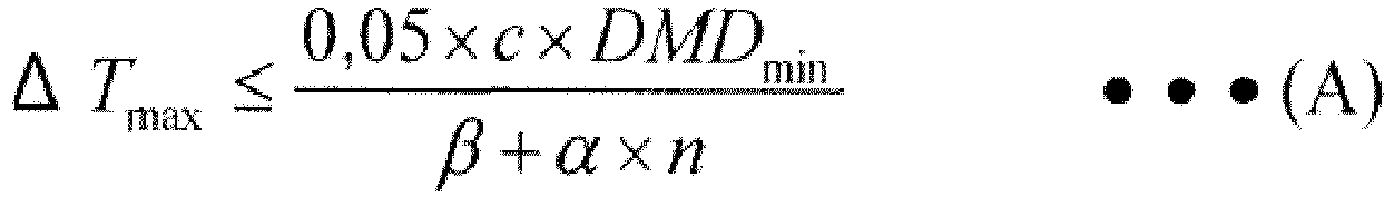
- ⁇ T max is the absolute value of the maximum variation that satisfies Formula (6).
- ⁇ T max The specific value of ⁇ T max is determined by the measured DMD min and ⁇ , ⁇ , and n in Formulae (1) - (5).
- DMD min 0.30 ps/m and 0.20 ps/m. These DMD min values were selected because they are considered appropriate in view of the measurement accuracy required by the DMD measurement (see the following supplementary explanation regarding DMD measurements). From the results of the calculation, it can be concluded that in order to maintain the measurement deviation within 5% or less of DMD min , the allowable temperature change should be maintained within ⁇ 0.4°C or ⁇ 0.3°C when the DMD min is 0.30 ps/m or 0.20 ps/m, respectively.
- the values in FIG. 2 are values determined from the average of the five measurements shown in Table 1. When the values were expressed by a formula, the following Formula (8) was obtained. In the following Formula (8), ⁇ t represents t measurement ⁇ (magnitude of shift of the pulse per unit time). Formula 8 ⁇ t DMD min ⁇ L
- a third method of the present invention is to reduce the measurement accuracy by combining the above-described first method with the second method.
- the DMD measurement is a measurement method which is defined in standard IEC/PAS 60793-1-49 (see Non-patent Document 2), and is a method for measuring the modal dispersion of a multimode optical fiber.
- the differential mode delay is a delay time difference between modes, and is defined as the difference in the pulse delay time between the fastest mode and the slowest mode in the radial direction offset of a fiber to be measured within a certain range (between R inner and Router).
- the points corresponding to 25% of the peak power of the offset are defined as a fast edge and a slow edge.
- the fastest value among fast edge values is defined as T fast and the slowest value among slow edge values is defined as T slow within a predetermined offset range (R of between 1 and 5 ⁇ m in FIG. 2 ).
- the value of DMD in this case is expressed by the following Formula (10).
- Formula 10 DMD T slow ⁇ T fast ⁇ ⁇ T REF
- ⁇ T REF is defined from the pulse duration ⁇ T pulse of the incident pulse and the broadening ⁇ t chrom due to the chromatic dispersion, and is expressed by the following Formula (11).
- Formula 11 ⁇ T REF ⁇ T 2 pulse + ⁇ t 2 chrom 1 / 2
- the range (inner) in which the radial direction offset is within the range of R of between 5 ⁇ m and 18 ⁇ m and the range (outer) in which it is within the range of R of between 0 ⁇ m and 23 ⁇ m are determined.
- An optical fiber compliant with Ala.2 of IEC 60793-2-10 which can propagate 300 m at 10 Gbps shall have two DMDs determined by the calculation method of the DMD and satisfying one of the six templates in Table 3.
Landscapes
- Physics & Mathematics (AREA)
- General Physics & Mathematics (AREA)
- Engineering & Computer Science (AREA)
- Mathematical Physics (AREA)
- Theoretical Computer Science (AREA)
- Analytical Chemistry (AREA)
- Chemical & Material Sciences (AREA)
- Data Mining & Analysis (AREA)
- Optics & Photonics (AREA)
- Mathematical Optimization (AREA)
- Databases & Information Systems (AREA)
- Software Systems (AREA)
- General Engineering & Computer Science (AREA)
- Pure & Applied Mathematics (AREA)
- Algebra (AREA)
- Mathematical Analysis (AREA)
- Computational Mathematics (AREA)
- Measuring Temperature Or Quantity Of Heat (AREA)
Claims (5)
- Procédé de mesure d'une fibre optique multimodale comprenant :la mesure d'un changement de température pendant une durée de mesure d'un DMD de la fibre optique multimodale,le contrôle de la température de la fibre optique pendant la durée de mesure,caractérisé en ce que ΔTmax étant la valeur absolue d'une amplitude d'un changement de température maximal de la fibre optique, ΔTmax satisfait une formule (A) suivante pendant la durée de mesure
- Procédé de mesure d'une fibre optique multimodale selon la revendication 1, dans lequel l'amplitude d'un changement de température ΔTmax est de 0,4 °C ou moins.
- Procédé de mesure d'une fibre optique multimodale selon la revendication 1, dans lequel l'amplitude d'un changement de température ΔTmax est de 0,3 °C ou moins.
- Procédé de mesure d'une fibre optique multimodale selon la revendication 1, dans lequel la durée de mesure est fixée à moins de 10 minutes.
- Procédé de mesure d'une fibre optique multimodale selon la revendication 1, dans lequel la durée de mesure est fixée à moins de 3 minutes.
Applications Claiming Priority (2)
| Application Number | Priority Date | Filing Date | Title |
|---|---|---|---|
| JP2004018512 | 2004-01-27 | ||
| PCT/JP2005/001007 WO2005071381A1 (fr) | 2004-01-27 | 2005-01-26 | Procede de mesure de fibre optique multimode |
Publications (3)
| Publication Number | Publication Date |
|---|---|
| EP1710552A1 EP1710552A1 (fr) | 2006-10-11 |
| EP1710552A4 EP1710552A4 (fr) | 2011-04-20 |
| EP1710552B1 true EP1710552B1 (fr) | 2016-09-21 |
Family
ID=34805571
Family Applications (1)
| Application Number | Title | Priority Date | Filing Date |
|---|---|---|---|
| EP05709347.8A Expired - Lifetime EP1710552B1 (fr) | 2004-01-27 | 2005-01-26 | Procede de mesure de fibre optique multimode |
Country Status (6)
| Country | Link |
|---|---|
| EP (1) | EP1710552B1 (fr) |
| JP (1) | JPWO2005071381A1 (fr) |
| KR (1) | KR101035862B1 (fr) |
| CN (1) | CN100543439C (fr) |
| DK (1) | DK1710552T3 (fr) |
| WO (1) | WO2005071381A1 (fr) |
Families Citing this family (7)
| Publication number | Priority date | Publication date | Assignee | Title |
|---|---|---|---|---|
| FR2940839B1 (fr) * | 2009-01-08 | 2012-09-14 | Draka Comteq France | Fibre optique multimodale a gradient d'indice, procedes de caracterisation et de fabrication d'une telle fibre |
| US8489369B2 (en) * | 2009-08-28 | 2013-07-16 | Panduit Corp. | Methods for calculating multimode fiber system bandwidth and manufacturing improved multimode fiber |
| NL2007976C2 (en) * | 2011-12-15 | 2013-06-18 | Draka Comteq Bv | A method for the characterization of optical properties of an optical fiber. |
| CN104198158A (zh) * | 2014-06-16 | 2014-12-10 | 中国电子科技集团公司第二十三研究所 | 一种光纤延迟量的温度特性的测量装置及测量方法 |
| DK3189320T3 (da) * | 2014-09-03 | 2020-07-13 | Draka Comteq Bv | Fremgangsmåde til kvalificering af den effektive modale båndbredde af en multimodefiber over et bredt bølgelængdeområde ud fra en enkelt bølgelængde-DMD-måling og fremgangsmåde til udvælgelse af en multimodefiber med højeffektiv modal båndbredde blandt et parti multimodefibre |
| US9753216B2 (en) | 2015-08-27 | 2017-09-05 | Sumitomo Electric Industries, Ltd. | Multimode optical fiber and optical cable including the same |
| CN111366180B (zh) * | 2020-05-08 | 2022-02-15 | 中天科技光纤有限公司 | 一种基于光纤传感器的外界参数测量方法 |
Family Cites Families (6)
| Publication number | Priority date | Publication date | Assignee | Title |
|---|---|---|---|---|
| JPS60214235A (ja) * | 1984-04-10 | 1985-10-26 | Hitachi Cable Ltd | 光フアイバの温度特性測定方法 |
| JPH05248996A (ja) * | 1992-03-09 | 1993-09-28 | Nippon Telegr & Teleph Corp <Ntt> | 光ファイバの波長分散測定装置 |
| EP1153323A4 (fr) * | 1999-02-22 | 2005-11-02 | Corning Inc | Fibre multimode et son procede de formation |
| US6400450B1 (en) * | 2000-03-17 | 2002-06-04 | Fitel Usa Corp. | Method of qualifying a multimode optical fiber for bandwidth performance |
| US6735985B2 (en) * | 2001-12-20 | 2004-05-18 | Furukawa Electric North America Inc | Method of impressing a twist on a multimode fiber during drawing |
| EP1347280A1 (fr) * | 2002-11-13 | 2003-09-24 | Agilent Technologies Inc. a Delaware Corporation | Dispositif et méthode de mesure de paramètres optiques avec les températures associées |
-
2005
- 2005-01-26 DK DK05709347.8T patent/DK1710552T3/en active
- 2005-01-26 EP EP05709347.8A patent/EP1710552B1/fr not_active Expired - Lifetime
- 2005-01-26 KR KR1020067014540A patent/KR101035862B1/ko not_active Expired - Fee Related
- 2005-01-26 JP JP2005517315A patent/JPWO2005071381A1/ja active Pending
- 2005-01-26 CN CNB2005800029672A patent/CN100543439C/zh not_active Expired - Fee Related
- 2005-01-26 WO PCT/JP2005/001007 patent/WO2005071381A1/fr not_active Ceased
Also Published As
| Publication number | Publication date |
|---|---|
| WO2005071381A1 (fr) | 2005-08-04 |
| CN100543439C (zh) | 2009-09-23 |
| KR101035862B1 (ko) | 2011-05-20 |
| CN1910435A (zh) | 2007-02-07 |
| JPWO2005071381A1 (ja) | 2007-09-06 |
| EP1710552A4 (fr) | 2011-04-20 |
| DK1710552T3 (en) | 2017-01-09 |
| KR20070005566A (ko) | 2007-01-10 |
| EP1710552A1 (fr) | 2006-10-11 |
Similar Documents
| Publication | Publication Date | Title |
|---|---|---|
| US7817257B2 (en) | Method for measuring a differential mode delay of a multimode optical fiber | |
| Fleming | Material and mode dispersion in GeO2· B2O3· SiC2 glasses | |
| CN101625437B (zh) | 多模光纤 | |
| EP2506045B1 (fr) | Fibre optique multimode | |
| EP1710552B1 (fr) | Procede de mesure de fibre optique multimode | |
| CN101479577B (zh) | 用参考光纤布拉格光栅监控和测量偏振保持光纤内器件的光学性质的方法及由此制作的光纤部件 | |
| CN103162938A (zh) | 用于表征光纤的光学性质的方法 | |
| JPH0815092A (ja) | 光導波路ファイバのスペクトル減衰を測定する方法 | |
| Hermann et al. | Refractive index of doped and undoped PCVD bulk silica | |
| US20060244949A1 (en) | Method of estimating and measuring longitudinal dispersion in optical fibers | |
| Fernandez et al. | In situ measurement of refractive index changes induced by gamma radiation in germanosilicate fibers | |
| Sladen et al. | Measurement of profile dispersion in optical fibres: A direct technique | |
| Anderson et al. | Length dependence of the effective cutoff wavelength in single-mode fibers | |
| Li et al. | Doubled optical path length for photonic bandgap fiber gas cell using micromirror | |
| Sladen et al. | Definitive profile-dispersion data for germania-doped silica fibres over an extended wavelength range | |
| US6904214B2 (en) | Method of providing an optical fiber having a minimum temperature sensitivity at a selected temperature | |
| Sladen et al. | Profile dispersion measurements for optical fibres over the wavelength range 350 to 1900nm | |
| JP3137585B2 (ja) | マイクロベンディング量の測定方法 | |
| Namkung et al. | Fiber optic distributed temperature sensor using Raman backscattering | |
| US6504962B2 (en) | Method for determining an aging condition for an optical waveguide grating and temperature sensor | |
| WO2020083999A1 (fr) | Réseau de fibre optique polymère multimode | |
| EP1906217A1 (fr) | Procédé de traitement de fibre optique | |
| Smiley et al. | Material dispersion measurements on fiber optic cables used at the Nevada test site | |
| Shao et al. | Highly Sensitive Torsion Sensor With Low Temperature Cross-Sensitivity Based on a Helical-Offset Ultra-Long-Period Fiber Grating | |
| Sladen et al. | A Method For The Direct Measurement Of The Inhomogeneous Dispersion Parameter In Optical Fibres |
Legal Events
| Date | Code | Title | Description |
|---|---|---|---|
| PUAI | Public reference made under article 153(3) epc to a published international application that has entered the european phase |
Free format text: ORIGINAL CODE: 0009012 |
|
| 17P | Request for examination filed |
Effective date: 20060801 |
|
| AK | Designated contracting states |
Kind code of ref document: A1 Designated state(s): DK NL |
|
| DAX | Request for extension of the european patent (deleted) | ||
| RBV | Designated contracting states (corrected) |
Designated state(s): DK NL |
|
| A4 | Supplementary search report drawn up and despatched |
Effective date: 20110322 |
|
| 17Q | First examination report despatched |
Effective date: 20110701 |
|
| GRAP | Despatch of communication of intention to grant a patent |
Free format text: ORIGINAL CODE: EPIDOSNIGR1 |
|
| RIC1 | Information provided on ipc code assigned before grant |
Ipc: G01M 11/00 20060101AFI20160422BHEP Ipc: G01M 99/00 20110101ALI20160422BHEP |
|
| INTG | Intention to grant announced |
Effective date: 20160527 |
|
| GRAS | Grant fee paid |
Free format text: ORIGINAL CODE: EPIDOSNIGR3 |
|
| GRAA | (expected) grant |
Free format text: ORIGINAL CODE: 0009210 |
|
| AK | Designated contracting states |
Kind code of ref document: B1 Designated state(s): DK NL |
|
| REG | Reference to a national code |
Ref country code: NL Ref legal event code: FP |
|
| REG | Reference to a national code |
Ref country code: DK Ref legal event code: T3 Effective date: 20170103 |
|
| PLBE | No opposition filed within time limit |
Free format text: ORIGINAL CODE: 0009261 |
|
| STAA | Information on the status of an ep patent application or granted ep patent |
Free format text: STATUS: NO OPPOSITION FILED WITHIN TIME LIMIT |
|
| 26N | No opposition filed |
Effective date: 20170622 |
|
| PGFP | Annual fee paid to national office [announced via postgrant information from national office to epo] |
Ref country code: NL Payment date: 20191212 Year of fee payment: 16 |
|
| PGFP | Annual fee paid to national office [announced via postgrant information from national office to epo] |
Ref country code: DK Payment date: 20200110 Year of fee payment: 16 |
|
| REG | Reference to a national code |
Ref country code: DK Ref legal event code: EBP Effective date: 20210131 |
|
| REG | Reference to a national code |
Ref country code: NL Ref legal event code: MM Effective date: 20210201 |
|
| PG25 | Lapsed in a contracting state [announced via postgrant information from national office to epo] |
Ref country code: NL Free format text: LAPSE BECAUSE OF NON-PAYMENT OF DUE FEES Effective date: 20210201 |
|
| PG25 | Lapsed in a contracting state [announced via postgrant information from national office to epo] |
Ref country code: DK Free format text: LAPSE BECAUSE OF NON-PAYMENT OF DUE FEES Effective date: 20210131 |