EP1710487A2 - Three color led bulb - Google Patents
Three color led bulb Download PDFInfo
- Publication number
- EP1710487A2 EP1710487A2 EP06006839A EP06006839A EP1710487A2 EP 1710487 A2 EP1710487 A2 EP 1710487A2 EP 06006839 A EP06006839 A EP 06006839A EP 06006839 A EP06006839 A EP 06006839A EP 1710487 A2 EP1710487 A2 EP 1710487A2
- Authority
- EP
- European Patent Office
- Prior art keywords
- light
- segment
- led
- light emitting
- segments
- Prior art date
- Legal status (The legal status is an assumption and is not a legal conclusion. Google has not performed a legal analysis and makes no representation as to the accuracy of the status listed.)
- Granted
Links
- 230000003287 optical effect Effects 0.000 claims 1
- 229910052782 aluminium Inorganic materials 0.000 abstract description 2
- XAGFODPZIPBFFR-UHFFFAOYSA-N aluminium Chemical compound [Al] XAGFODPZIPBFFR-UHFFFAOYSA-N 0.000 abstract description 2
- 229910052751 metal Inorganic materials 0.000 description 2
- 239000002184 metal Substances 0.000 description 2
- 238000000926 separation method Methods 0.000 description 2
- NIXOWILDQLNWCW-UHFFFAOYSA-N acrylic acid group Chemical group C(C=C)(=O)O NIXOWILDQLNWCW-UHFFFAOYSA-N 0.000 description 1
- 230000000740 bleeding effect Effects 0.000 description 1
- 239000003086 colorant Substances 0.000 description 1
- 239000000463 material Substances 0.000 description 1
- 230000004048 modification Effects 0.000 description 1
- 238000012986 modification Methods 0.000 description 1
- 239000002991 molded plastic Substances 0.000 description 1
- 230000002093 peripheral effect Effects 0.000 description 1
Images



Classifications
-
- F—MECHANICAL ENGINEERING; LIGHTING; HEATING; WEAPONS; BLASTING
- F21—LIGHTING
- F21K—NON-ELECTRIC LIGHT SOURCES USING LUMINESCENCE; LIGHT SOURCES USING ELECTROCHEMILUMINESCENCE; LIGHT SOURCES USING CHARGES OF COMBUSTIBLE MATERIAL; LIGHT SOURCES USING SEMICONDUCTOR DEVICES AS LIGHT-GENERATING ELEMENTS; LIGHT SOURCES NOT OTHERWISE PROVIDED FOR
- F21K9/00—Light sources using semiconductor devices as light-generating elements, e.g. using light-emitting diodes [LED] or lasers
-
- F—MECHANICAL ENGINEERING; LIGHTING; HEATING; WEAPONS; BLASTING
- F21—LIGHTING
- F21K—NON-ELECTRIC LIGHT SOURCES USING LUMINESCENCE; LIGHT SOURCES USING ELECTROCHEMILUMINESCENCE; LIGHT SOURCES USING CHARGES OF COMBUSTIBLE MATERIAL; LIGHT SOURCES USING SEMICONDUCTOR DEVICES AS LIGHT-GENERATING ELEMENTS; LIGHT SOURCES NOT OTHERWISE PROVIDED FOR
- F21K9/00—Light sources using semiconductor devices as light-generating elements, e.g. using light-emitting diodes [LED] or lasers
- F21K9/60—Optical arrangements integrated in the light source, e.g. for improving the colour rendering index or the light extraction
- F21K9/61—Optical arrangements integrated in the light source, e.g. for improving the colour rendering index or the light extraction using light guides
-
- F—MECHANICAL ENGINEERING; LIGHTING; HEATING; WEAPONS; BLASTING
- F21—LIGHTING
- F21V—FUNCTIONAL FEATURES OR DETAILS OF LIGHTING DEVICES OR SYSTEMS THEREOF; STRUCTURAL COMBINATIONS OF LIGHTING DEVICES WITH OTHER ARTICLES, NOT OTHERWISE PROVIDED FOR
- F21V29/00—Protecting lighting devices from thermal damage; Cooling or heating arrangements specially adapted for lighting devices or systems
- F21V29/50—Cooling arrangements
- F21V29/70—Cooling arrangements characterised by passive heat-dissipating elements, e.g. heat-sinks
-
- F—MECHANICAL ENGINEERING; LIGHTING; HEATING; WEAPONS; BLASTING
- F21—LIGHTING
- F21V—FUNCTIONAL FEATURES OR DETAILS OF LIGHTING DEVICES OR SYSTEMS THEREOF; STRUCTURAL COMBINATIONS OF LIGHTING DEVICES WITH OTHER ARTICLES, NOT OTHERWISE PROVIDED FOR
- F21V29/00—Protecting lighting devices from thermal damage; Cooling or heating arrangements specially adapted for lighting devices or systems
- F21V29/85—Protecting lighting devices from thermal damage; Cooling or heating arrangements specially adapted for lighting devices or systems characterised by the material
- F21V29/89—Metals
-
- F—MECHANICAL ENGINEERING; LIGHTING; HEATING; WEAPONS; BLASTING
- F21—LIGHTING
- F21S—NON-PORTABLE LIGHTING DEVICES; SYSTEMS THEREOF; VEHICLE LIGHTING DEVICES SPECIALLY ADAPTED FOR VEHICLE EXTERIORS
- F21S43/00—Signalling devices specially adapted for vehicle exteriors, e.g. brake lamps, direction indicator lights or reversing lights
- F21S43/10—Signalling devices specially adapted for vehicle exteriors, e.g. brake lamps, direction indicator lights or reversing lights characterised by the light source
- F21S43/13—Signalling devices specially adapted for vehicle exteriors, e.g. brake lamps, direction indicator lights or reversing lights characterised by the light source characterised by the type of light source
- F21S43/14—Light emitting diodes [LED]
-
- F—MECHANICAL ENGINEERING; LIGHTING; HEATING; WEAPONS; BLASTING
- F21—LIGHTING
- F21Y—INDEXING SCHEME ASSOCIATED WITH SUBCLASSES F21K, F21L, F21S and F21V, RELATING TO THE FORM OR THE KIND OF THE LIGHT SOURCES OR OF THE COLOUR OF THE LIGHT EMITTED
- F21Y2113/00—Combination of light sources
- F21Y2113/10—Combination of light sources of different colours
- F21Y2113/13—Combination of light sources of different colours comprising an assembly of point-like light sources
-
- F—MECHANICAL ENGINEERING; LIGHTING; HEATING; WEAPONS; BLASTING
- F21—LIGHTING
- F21Y—INDEXING SCHEME ASSOCIATED WITH SUBCLASSES F21K, F21L, F21S and F21V, RELATING TO THE FORM OR THE KIND OF THE LIGHT SOURCES OR OF THE COLOUR OF THE LIGHT EMITTED
- F21Y2115/00—Light-generating elements of semiconductor light sources
- F21Y2115/10—Light-emitting diodes [LED]
-
- Y—GENERAL TAGGING OF NEW TECHNOLOGICAL DEVELOPMENTS; GENERAL TAGGING OF CROSS-SECTIONAL TECHNOLOGIES SPANNING OVER SEVERAL SECTIONS OF THE IPC; TECHNICAL SUBJECTS COVERED BY FORMER USPC CROSS-REFERENCE ART COLLECTIONS [XRACs] AND DIGESTS
- Y10—TECHNICAL SUBJECTS COVERED BY FORMER USPC
- Y10S—TECHNICAL SUBJECTS COVERED BY FORMER USPC CROSS-REFERENCE ART COLLECTIONS [XRACs] AND DIGESTS
- Y10S362/00—Illumination
- Y10S362/80—Light emitting diode
Definitions
- This invention generally relates to lamps and more particularly to lamps employing light emitting diodes. Still more particularly it relates to multi-color light emitting lamps for automotive vehicles.
- the rear of automotive vehicles typically is provided with separate lamps emitting three different colors of light; e.g., red for the tail light and stop light, amber or yellow for the turn signal and white for the backup light.
- the lamps are fitted into apertures in the automotive body and have replaceable bulbs.
- the bulbs for the lamps in the past have been filamented incandescent bulbs.
- Recently, some of the incandescent bulbs, particularly the center high mount stoplight, have been replaced with red emitting light emitting diodes (LED or LEDs).
- LED or LEDs red emitting light emitting diodes
- a multi-color light lamp comprising: a base divided into a plurality of segments; at least one LED operatively positioned in each segment, the at least one LED in each segment emitting light in a color distinct from the light emitted by the at least one LED in the other segments; and a light pipe operatively associated with the at least one LED in each segment for directing emitted light away from said base.
- the base includes a central mounting aperture containing a fastener that is directly affixed to a vehicle body, thereby utilizing the vehicle body as the heat sink.
- a multi-color light lamp 10 comprising a base 12 divided into a plurality of segments 14. In the embodiment shown there are three segments spaced 120 degrees apart. More or less segments can be employed if desired. At least one LED 16 is operatively positioned in each segment 14, the at least one LED 16 in each segment 14 emitting light in a color distinct from the light emitted by the at least one LED 16 in the other segments 14.
- the LEDs in a first segment can emit red light to be used as a taillight and a stop light
- the LEDs in a second segment can emit yellow light to be used as a turn signal lamp
- the LEDs in the third segment can emit white light to function as a backup light.
- a light pipe 18 is operatively associated with the LEDs 16 in each segment for directing emitted light away from the base 12.
- the LEDs 16 (preferably two per segment) are mounted upon a thermally efficient printed circuit board 20 such as a flex-on aluminum board.
- the base 12 includes a central mounting aperture 22 that can include a fastener 24, for example, a threaded bolt.
- the center of the base 12 can be provided with an infrared emitter or sensor in the central aperture 22 and peripheral attachment apertures can be provided.
- the lamp 10 is mounted directly to a vehicle body.
- a metal vehicle body 26 can be provided with a formed boss 30 to which the lamp 10 is attached via the fastener 24.
- the vehicle body itself acts as a heat sink for removing excess heat from the operating LEDs 16.
- the light pipes 18 can be individually formed and attached relative to the LEDs, in a preferred embodiment the light pipes 18 are integrally formed with the base 12 as shown in the drawings.
- a suitable material for the light pipes and base is a molded plastic such as acrylic.
- Separators 18a between the respective segments 14 can be also be provided to aid in color separation.
- the underside of the printed circuit board 20 can be provided with raised ribs 20a for engaging the metal vehicle body 26.
- spaces 12a can be provided in the base 12 intermediate the segments 14 to provide space for any necessary or desired electrical components while spaces 12b will accommodate the LEDs 16.
- the light pipes 18 accomplish this separation.
- the light pipes 18 receive, direct and shape the colored light input and guide it in directions that are visually distinct while preventing one color from bleeding into another.
Landscapes
- Engineering & Computer Science (AREA)
- General Engineering & Computer Science (AREA)
- Physics & Mathematics (AREA)
- Microelectronics & Electronic Packaging (AREA)
- Optics & Photonics (AREA)
- Non-Portable Lighting Devices Or Systems Thereof (AREA)
- Arrangement Of Elements, Cooling, Sealing, Or The Like Of Lighting Devices (AREA)
- Led Device Packages (AREA)
- Lighting Device Outwards From Vehicle And Optical Signal (AREA)
- Fastening Of Light Sources Or Lamp Holders (AREA)
Abstract
Description
- This invention generally relates to lamps and more particularly to lamps employing light emitting diodes. Still more particularly it relates to multi-color light emitting lamps for automotive vehicles.
- The rear of automotive vehicles typically is provided with separate lamps emitting three different colors of light; e.g., red for the tail light and stop light, amber or yellow for the turn signal and white for the backup light. The lamps are fitted into apertures in the automotive body and have replaceable bulbs. The bulbs for the lamps in the past have been filamented incandescent bulbs. Recently, some of the incandescent bulbs, particularly the center high mount stoplight, have been replaced with red emitting light emitting diodes (LED or LEDs). These solid-state light sources are efficient and have long life; however, they tend to generate a considerable amount of heat under continuous operation, such as would be encountered in a tail light as opposed to the intermittent operation of a stoplight. To dissipate the generated heat it is necessary to provide a viable heat sink. It would be an advance in the art if a single lamp could be provided for all three light functions. It would be a further advance in the art if the vehicle itself could provide the heat sinking function.
- It is, therefore, an object of the invention to obviate the disadvantages of the prior art.
- It is another object of the invention to enhance automotive lighting.
- It is yet another object of the invention to provide a lamp that utilizes the vehicle body as its primary heat sink.
- These objects are accomplished, in one aspect of the invention, by a multi-color light lamp comprising: a base divided into a plurality of segments; at least one LED operatively positioned in each segment, the at least one LED in each segment emitting light in a color distinct from the light emitted by the at least one LED in the other segments; and a light pipe operatively associated with the at least one LED in each segment for directing emitted light away from said base.
- In a preferred embodiment of the invention, the base includes a central mounting aperture containing a fastener that is directly affixed to a vehicle body, thereby utilizing the vehicle body as the heat sink.
-
- Fig. 1 is a perspective view of an embodiment of a lamp of the invention without a cover;
- Fig. 2 is a plan view of the lamp of Fig. 1;
- Fig. 3 is a sectional view taken along the line 3-3 of fig. 2;
- Fig. 4 is a plan view of the underside of an optic; and
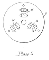
- Fig. 5 is a plan view of a base for the lamp.
- For a better understanding of the present invention, together with other and further objects, advantages and capabilities thereof, reference is made to the following disclosure and appended claims taken in conjunction with the above-described drawings.
- Referring now to the drawings with greater particularity, there is shown in Fig. 1 a
multi-color light lamp 10 comprising abase 12 divided into a plurality ofsegments 14. In the embodiment shown there are three segments spaced 120 degrees apart. More or less segments can be employed if desired. At least oneLED 16 is operatively positioned in eachsegment 14, the at least oneLED 16 in eachsegment 14 emitting light in a color distinct from the light emitted by the at least oneLED 16 in theother segments 14. Preferably, if the lamp is to be used for automotive purposes, the LEDs in a first segment can emit red light to be used as a taillight and a stop light, the LEDs in a second segment can emit yellow light to be used as a turn signal lamp, and the LEDs in the third segment can emit white light to function as a backup light. Alight pipe 18 is operatively associated with theLEDs 16 in each segment for directing emitted light away from thebase 12. The LEDs 16 (preferably two per segment) are mounted upon a thermally efficient printedcircuit board 20 such as a flex-on aluminum board. - In one embodiment of the invention the
base 12 includes acentral mounting aperture 22 that can include afastener 24, for example, a threaded bolt. - Alternatively, the center of the
base 12 can be provided with an infrared emitter or sensor in thecentral aperture 22 and peripheral attachment apertures can be provided. - Ideally, the
lamp 10 is mounted directly to a vehicle body. For example, ametal vehicle body 26 can be provided with a formedboss 30 to which thelamp 10 is attached via thefastener 24. In this instance, the vehicle body itself acts as a heat sink for removing excess heat from theoperating LEDs 16. - While the
light pipes 18 can be individually formed and attached relative to the LEDs, in a preferred embodiment thelight pipes 18 are integrally formed with thebase 12 as shown in the drawings. A suitable material for the light pipes and base is a molded plastic such as acrylic.Separators 18a between therespective segments 14 can be also be provided to aid in color separation. - To further insure good heat-sinking capability, the underside of the printed
circuit board 20 can be provided with raisedribs 20a for engaging themetal vehicle body 26. - Likewise,
spaces 12a can be provided in thebase 12 intermediate thesegments 14 to provide space for any necessary or desired electrical components while spaces 12b will accommodate theLEDs 16. - Since the red, amber and white light need to be visually separated the
light pipes 18 accomplish this separation. Thelight pipes 18 receive, direct and shape the colored light input and guide it in directions that are visually distinct while preventing one color from bleeding into another. - While there have been shown and described what are present considered to be the preferred embodiments of the invention, it will be apparent to those skilled in the art that various changes and modifications can be made herein without departing from the scope of the invention as defined by the appended claims.
Claims (10)
- A multi-color light emitting lamp comprising:a base divided into a plurality of segments;at least one LED operatively positioned in each segment, the at least one LED in each segment emitting light in a color distinct from the light emitted by the at least one LED in the other segments; anda light pipe operatively associated with the at least one LED in each segment for directing emitted light away from said base.
- The multi-color light emitting lamp of Claim 1 wherein said LEDs are mounted upon a thermally efficient printed circuit board.
- The multi-color light emitting lamp of Claim 2 wherein said segments are three in number.
- The multi-color light emitting lamp of Claim 3 wherein a first of said LEDs emits red light, a second of said LEDs emits yellow light and a third of said LEDs emits white light.
- The multi-color light emitting lamp of Claim 4 wherein said base includes a central mounting aperture.
- The multi-color light emitting lamp of Claim 5 wherein said central mounting aperture includes a fastener.
- The multi-color light emitting lamp of Claim 6 wherein said fastener is affixed to a vehicle body.
- The multi-color light emitting lamp of Claim 7 wherein an optical plate is provided over said segments.
- The multi-color light emitting lamp of Claim 4 wherein said base includes a plurality of peripherally located mounting apertures.
- The multi-color light emitting lamp of Claim 9 wherein said base includes a center-mounted infra-red source.
Applications Claiming Priority (1)
| Application Number | Priority Date | Filing Date | Title |
|---|---|---|---|
| US11/098,812 US7275839B2 (en) | 2005-04-05 | 2005-04-05 | Three color LED bulb |
Publications (3)
| Publication Number | Publication Date |
|---|---|
| EP1710487A2 true EP1710487A2 (en) | 2006-10-11 |
| EP1710487A3 EP1710487A3 (en) | 2007-12-19 |
| EP1710487B1 EP1710487B1 (en) | 2010-12-01 |
Family
ID=36282883
Family Applications (1)
| Application Number | Title | Priority Date | Filing Date |
|---|---|---|---|
| EP06006839A Expired - Lifetime EP1710487B1 (en) | 2005-04-05 | 2006-03-31 | Three color led bulb |
Country Status (8)
| Country | Link |
|---|---|
| US (1) | US7275839B2 (en) |
| EP (1) | EP1710487B1 (en) |
| JP (1) | JP4970826B2 (en) |
| KR (1) | KR101220685B1 (en) |
| CN (1) | CN1862085B (en) |
| CA (1) | CA2533586A1 (en) |
| DE (1) | DE602006018551D1 (en) |
| ES (1) | ES2356831T3 (en) |
Families Citing this family (58)
| Publication number | Priority date | Publication date | Assignee | Title |
|---|---|---|---|---|
| US7520635B2 (en) | 2003-07-02 | 2009-04-21 | S.C. Johnson & Son, Inc. | Structures for color changing light devices |
| US7484860B2 (en) | 2003-07-02 | 2009-02-03 | S.C. Johnson & Son, Inc. | Combination white light and colored LED light device with active ingredient emission |
| US7318659B2 (en) * | 2004-03-03 | 2008-01-15 | S. C. Johnson & Son, Inc. | Combination white light and colored LED light device with active ingredient emission |
| US7476002B2 (en) | 2003-07-02 | 2009-01-13 | S.C. Johnson & Son, Inc. | Color changing light devices with active ingredient and sound emission for mood enhancement |
| US7604378B2 (en) | 2003-07-02 | 2009-10-20 | S.C. Johnson & Son, Inc. | Color changing outdoor lights with active ingredient and sound emission |
| US7422355B2 (en) * | 2003-09-30 | 2008-09-09 | Youth Engineering Co., Ltd | Illumination device |
| AU2005219978B2 (en) | 2004-03-03 | 2010-08-26 | S.C. Johnson & Son, Inc. | LED light bulb with active ingredient emission |
| US7503675B2 (en) | 2004-03-03 | 2009-03-17 | S.C. Johnson & Son, Inc. | Combination light device with insect control ingredient emission |
| US7416324B1 (en) * | 2005-06-22 | 2008-08-26 | Osram Sylvania Inc. | Multi-color or multi-function LED vehicle light assembly |
| JP4989170B2 (en) * | 2006-09-20 | 2012-08-01 | オスラム・メルコ株式会社 | Compact LED lamp |
| CN101413652B (en) * | 2007-10-16 | 2010-11-10 | 富士迈半导体精密工业(上海)有限公司 | Light-emitting diode light source device |
| US20090314945A1 (en) * | 2008-06-24 | 2009-12-24 | Chen Kai-Po | Lighting device having detection function |
| EP2313800A4 (en) | 2008-07-10 | 2014-03-19 | 3M Innovative Properties Co | Viscoelastic lightguide |
| EP2321677A4 (en) | 2008-08-08 | 2011-08-17 | 3M Innovative Properties Co | Lightguide having a viscoelastic layer for managing light |
| US20110063214A1 (en) * | 2008-09-05 | 2011-03-17 | Knapp David J | Display and optical pointer systems and related methods |
| US8674913B2 (en) | 2008-09-05 | 2014-03-18 | Ketra, Inc. | LED transceiver front end circuitry and related methods |
| US8773336B2 (en) * | 2008-09-05 | 2014-07-08 | Ketra, Inc. | Illumination devices and related systems and methods |
| US8471496B2 (en) * | 2008-09-05 | 2013-06-25 | Ketra, Inc. | LED calibration systems and related methods |
| US8456092B2 (en) * | 2008-09-05 | 2013-06-04 | Ketra, Inc. | Broad spectrum light source calibration systems and related methods |
| US9509525B2 (en) * | 2008-09-05 | 2016-11-29 | Ketra, Inc. | Intelligent illumination device |
| US9276766B2 (en) | 2008-09-05 | 2016-03-01 | Ketra, Inc. | Display calibration systems and related methods |
| USRE50468E1 (en) | 2008-09-05 | 2025-06-24 | Lutron Technology Company Llc | Intelligent illumination device |
| US10210750B2 (en) | 2011-09-13 | 2019-02-19 | Lutron Electronics Co., Inc. | System and method of extending the communication range in a visible light communication system |
| US8521035B2 (en) | 2008-09-05 | 2013-08-27 | Ketra, Inc. | Systems and methods for visible light communication |
| WO2010027459A2 (en) | 2008-09-05 | 2010-03-11 | Firefly Green Technologies Inc. | Optical communication device, method and system |
| JP5463095B2 (en) * | 2008-09-08 | 2014-04-09 | 株式会社小糸製作所 | Infrared light irradiation lamp for vehicles |
| DE202008016867U1 (en) * | 2008-12-19 | 2009-03-19 | Osram Gesellschaft mit beschränkter Haftung | lamp |
| USRE49454E1 (en) | 2010-09-30 | 2023-03-07 | Lutron Technology Company Llc | Lighting control system |
| US9386668B2 (en) | 2010-09-30 | 2016-07-05 | Ketra, Inc. | Lighting control system |
| US8749172B2 (en) | 2011-07-08 | 2014-06-10 | Ketra, Inc. | Luminance control for illumination devices |
| US9010975B2 (en) | 2013-03-12 | 2015-04-21 | Grote Industries, Inc. | Multi-colored vehicle rear lamp |
| US9155155B1 (en) | 2013-08-20 | 2015-10-06 | Ketra, Inc. | Overlapping measurement sequences for interference-resistant compensation in light emitting diode devices |
| US9651632B1 (en) | 2013-08-20 | 2017-05-16 | Ketra, Inc. | Illumination device and temperature calibration method |
| USRE48956E1 (en) | 2013-08-20 | 2022-03-01 | Lutron Technology Company Llc | Interference-resistant compensation for illumination devices using multiple series of measurement intervals |
| US9578724B1 (en) | 2013-08-20 | 2017-02-21 | Ketra, Inc. | Illumination device and method for avoiding flicker |
| USRE48955E1 (en) | 2013-08-20 | 2022-03-01 | Lutron Technology Company Llc | Interference-resistant compensation for illumination devices having multiple emitter modules |
| US9332598B1 (en) | 2013-08-20 | 2016-05-03 | Ketra, Inc. | Interference-resistant compensation for illumination devices having multiple emitter modules |
| US9360174B2 (en) | 2013-12-05 | 2016-06-07 | Ketra, Inc. | Linear LED illumination device with improved color mixing |
| US9237620B1 (en) | 2013-08-20 | 2016-01-12 | Ketra, Inc. | Illumination device and temperature compensation method |
| US9769899B2 (en) | 2014-06-25 | 2017-09-19 | Ketra, Inc. | Illumination device and age compensation method |
| US9247605B1 (en) | 2013-08-20 | 2016-01-26 | Ketra, Inc. | Interference-resistant compensation for illumination devices |
| US9345097B1 (en) | 2013-08-20 | 2016-05-17 | Ketra, Inc. | Interference-resistant compensation for illumination devices using multiple series of measurement intervals |
| US9736895B1 (en) | 2013-10-03 | 2017-08-15 | Ketra, Inc. | Color mixing optics for LED illumination device |
| US9146028B2 (en) | 2013-12-05 | 2015-09-29 | Ketra, Inc. | Linear LED illumination device with improved rotational hinge |
| US9103520B1 (en) | 2014-04-18 | 2015-08-11 | Osram Sylvania Inc. | Combination turn and tail multi-color LED lamp |
| US9736903B2 (en) | 2014-06-25 | 2017-08-15 | Ketra, Inc. | Illumination device and method for calibrating and controlling an illumination device comprising a phosphor converted LED |
| US9557214B2 (en) | 2014-06-25 | 2017-01-31 | Ketra, Inc. | Illumination device and method for calibrating an illumination device over changes in temperature, drive current, and time |
| US10161786B2 (en) | 2014-06-25 | 2018-12-25 | Lutron Ketra, Llc | Emitter module for an LED illumination device |
| US9392663B2 (en) | 2014-06-25 | 2016-07-12 | Ketra, Inc. | Illumination device and method for controlling an illumination device over changes in drive current and temperature |
| US9510416B2 (en) | 2014-08-28 | 2016-11-29 | Ketra, Inc. | LED illumination device and method for accurately controlling the intensity and color point of the illumination device over time |
| US9392660B2 (en) | 2014-08-28 | 2016-07-12 | Ketra, Inc. | LED illumination device and calibration method for accurately characterizing the emission LEDs and photodetector(s) included within the LED illumination device |
| US9485813B1 (en) | 2015-01-26 | 2016-11-01 | Ketra, Inc. | Illumination device and method for avoiding an over-power or over-current condition in a power converter |
| US9237623B1 (en) | 2015-01-26 | 2016-01-12 | Ketra, Inc. | Illumination device and method for determining a maximum lumens that can be safely produced by the illumination device to achieve a target chromaticity |
| US9237612B1 (en) | 2015-01-26 | 2016-01-12 | Ketra, Inc. | Illumination device and method for determining a target lumens that can be safely produced by an illumination device at a present temperature |
| US9868546B2 (en) * | 2015-06-22 | 2018-01-16 | Goodrich Lighting Systems, Inc. | Dual-mode vehicle light system |
| US10436416B2 (en) | 2017-07-19 | 2019-10-08 | Ford Global Technologies, Llc | Vehicle light assembly with heat sink |
| US11272599B1 (en) | 2018-06-22 | 2022-03-08 | Lutron Technology Company Llc | Calibration procedure for a light-emitting diode light source |
| EP4667817A1 (en) | 2024-06-18 | 2025-12-24 | Hella Autotechnik Nova s.r.o. | Multicolor vehicle lamp and primary optical element for the lamp |
Family Cites Families (21)
| Publication number | Priority date | Publication date | Assignee | Title |
|---|---|---|---|---|
| JPS5834301U (en) * | 1981-08-31 | 1983-03-05 | スタンレー電気株式会社 | Vehicle indicator light |
| JPH0711365Y2 (en) * | 1990-03-30 | 1995-03-15 | アロー電子工業株式会社 | Indicator light |
| JPH0454103U (en) * | 1990-09-14 | 1992-05-08 | ||
| DE4129094B4 (en) * | 1991-09-02 | 2005-08-25 | Hella Kgaa Hueck & Co. | Signal light with LEDs as a light source for motor vehicles and their use for different signal light functions |
| US5335155A (en) * | 1992-11-23 | 1994-08-02 | Wesbar Corporation | Tail light construction |
| GB9320291D0 (en) * | 1993-10-01 | 1993-11-17 | Brown John H | Optical directing devices for light emitting diodes |
| US6550949B1 (en) * | 1996-06-13 | 2003-04-22 | Gentex Corporation | Systems and components for enhancing rear vision from a vehicle |
| DE19943821A1 (en) * | 1999-09-14 | 2001-03-15 | Valeo Beleuchtung Deutschland | Lights, in particular for motor vehicles |
| DE10036346A1 (en) * | 2000-07-26 | 2002-03-07 | Hella Kg Hueck & Co | Vehicle light e.g. rear light, has grooved reflectors in rows and columns at intervals and light rods arranged in plane in front of reflectors looking in light emanation direction and between reflectors |
| US6527411B1 (en) * | 2000-08-01 | 2003-03-04 | Visteon Corporation | Collimating lamp |
| JP2002184209A (en) * | 2000-12-19 | 2002-06-28 | Matsushita Electric Ind Co Ltd | Lighting equipment |
| US6585395B2 (en) * | 2001-03-22 | 2003-07-01 | Altman Stage Lighting Co., Inc. | Variable beam light emitting diode light source system |
| US6682211B2 (en) * | 2001-09-28 | 2004-01-27 | Osram Sylvania Inc. | Replaceable LED lamp capsule |
| CN1416171A (en) * | 2001-10-29 | 2003-05-07 | 欧阳伟 | Illuminator capable of changing color freely |
| DE10160938A1 (en) * | 2001-12-12 | 2003-07-10 | Hella Kg Hueck & Co | Light for vehicle has LEDs on carrier, optical bodies with optical body sections that are all of a solid structure with a cup-shaped contour facing against the light propagation direction |
| US7093958B2 (en) * | 2002-04-09 | 2006-08-22 | Osram Sylvania Inc. | LED light source assembly |
| DE10231326A1 (en) * | 2002-07-11 | 2004-02-19 | Hella Kg Hueck & Co. | Light unit for automobile e.g. automobile headlamp, has spaced light source elements associated with light conduction elements positioned behind light disc |
| JP2004047351A (en) * | 2002-07-15 | 2004-02-12 | Koito Mfg Co Ltd | Vehicle lighting |
| US7329034B2 (en) * | 2003-03-05 | 2008-02-12 | Dialight Corporation | Multi-level surface mounted lightpipe package design with LED light sources |
| JP4138586B2 (en) * | 2003-06-13 | 2008-08-27 | スタンレー電気株式会社 | LED lamp for light source and vehicle headlamp using the same |
| DE102004063574A1 (en) * | 2004-12-30 | 2006-07-13 | Osram Opto Semiconductors Gmbh | Lighting device with multiple semiconductor light sources |
-
2005
- 2005-04-05 US US11/098,812 patent/US7275839B2/en not_active Expired - Fee Related
-
2006
- 2006-01-23 CA CA002533586A patent/CA2533586A1/en not_active Abandoned
- 2006-03-31 DE DE602006018551T patent/DE602006018551D1/en not_active Expired - Fee Related
- 2006-03-31 ES ES06006839T patent/ES2356831T3/en not_active Expired - Lifetime
- 2006-03-31 EP EP06006839A patent/EP1710487B1/en not_active Expired - Lifetime
- 2006-04-04 KR KR1020060030594A patent/KR101220685B1/en not_active Expired - Fee Related
- 2006-04-05 JP JP2006104565A patent/JP4970826B2/en not_active Expired - Fee Related
- 2006-04-05 CN CN2006100732024A patent/CN1862085B/en not_active Expired - Fee Related
Non-Patent Citations (1)
| Title |
|---|
| None |
Also Published As
| Publication number | Publication date |
|---|---|
| US20060220990A1 (en) | 2006-10-05 |
| ES2356831T3 (en) | 2011-04-13 |
| EP1710487A3 (en) | 2007-12-19 |
| CA2533586A1 (en) | 2006-10-05 |
| KR20060107322A (en) | 2006-10-13 |
| CN1862085B (en) | 2012-05-09 |
| JP4970826B2 (en) | 2012-07-11 |
| DE602006018551D1 (en) | 2011-01-13 |
| EP1710487B1 (en) | 2010-12-01 |
| US7275839B2 (en) | 2007-10-02 |
| CN1862085A (en) | 2006-11-15 |
| JP2006294611A (en) | 2006-10-26 |
| KR101220685B1 (en) | 2013-01-11 |
Similar Documents
| Publication | Publication Date | Title |
|---|---|---|
| US7275839B2 (en) | Three color LED bulb | |
| US6414801B1 (en) | Catadioptric light emitting diode assembly | |
| US20030031028A1 (en) | Vehicle emergency warning light having TIR lens, LED light engine and heat sink | |
| US8398283B2 (en) | Automotive signal light employing multi-focal length light pipes | |
| US5136483A (en) | Illuminating device | |
| US6929390B2 (en) | Vehicular lamp | |
| US20140146540A1 (en) | LED Lighting Fixture | |
| EP1607677A1 (en) | Light emitting diode lamp with conical reflector | |
| EP1912017B1 (en) | Vehicular lamp | |
| US20150098233A1 (en) | Light guiding device for vehicle headlights | |
| CN107435882A (en) | Lighting device | |
| EP2839989A1 (en) | Vehicle light apparatus | |
| CN112888894B (en) | Lighting unit for a motor vehicle headlight | |
| CN210373270U (en) | Warning light lamp for vehicle | |
| KR101411206B1 (en) | LED Lingting Device For Vehicle | |
| JP6470020B2 (en) | Lighting device | |
| US8974081B2 (en) | LED lamp | |
| CN100537299C (en) | Method for automotive lights and vehicle controlling light at least | |
| US20130170183A1 (en) | Led lamp | |
| EP2184531A1 (en) | Warning lamp | |
| US8931941B2 (en) | Vehicular light-emitting diode light providing uniform wider illumination | |
| KR102012662B1 (en) | Tail lamp for vehicle with light guide film and flexible lighting | |
| JPH10228803A (en) | Vehicle headlights | |
| US20240230052A1 (en) | Vehicle signal lighting assembly | |
| TWI681144B (en) | Lighting device |
Legal Events
| Date | Code | Title | Description |
|---|---|---|---|
| PUAI | Public reference made under article 153(3) epc to a published international application that has entered the european phase |
Free format text: ORIGINAL CODE: 0009012 |
|
| AK | Designated contracting states |
Kind code of ref document: A2 Designated state(s): AT BE BG CH CY CZ DE DK EE ES FI FR GB GR HU IE IS IT LI LT LU LV MC NL PL PT RO SE SI SK TR |
|
| AX | Request for extension of the european patent |
Extension state: AL BA HR MK YU |
|
| PUAL | Search report despatched |
Free format text: ORIGINAL CODE: 0009013 |
|
| AK | Designated contracting states |
Kind code of ref document: A3 Designated state(s): AT BE BG CH CY CZ DE DK EE ES FI FR GB GR HU IE IS IT LI LT LU LV MC NL PL PT RO SE SI SK TR |
|
| AX | Request for extension of the european patent |
Extension state: AL BA HR MK YU |
|
| 17P | Request for examination filed |
Effective date: 20080124 |
|
| 17Q | First examination report despatched |
Effective date: 20080305 |
|
| AKX | Designation fees paid |
Designated state(s): DE ES FR GB IT |
|
| GRAP | Despatch of communication of intention to grant a patent |
Free format text: ORIGINAL CODE: EPIDOSNIGR1 |
|
| RAP1 | Party data changed (applicant data changed or rights of an application transferred) |
Owner name: OSRAM GESELLSCHAFT MIT BESCHRAENKTER HAFTUNG |
|
| RIC1 | Information provided on ipc code assigned before grant |
Ipc: F21K 99/00 20100101AFI20100528BHEP |
|
| GRAS | Grant fee paid |
Free format text: ORIGINAL CODE: EPIDOSNIGR3 |
|
| GRAA | (expected) grant |
Free format text: ORIGINAL CODE: 0009210 |
|
| AK | Designated contracting states |
Kind code of ref document: B1 Designated state(s): DE ES FR GB IT |
|
| REG | Reference to a national code |
Ref country code: GB Ref legal event code: FG4D |
|
| REF | Corresponds to: |
Ref document number: 602006018551 Country of ref document: DE Date of ref document: 20110113 Kind code of ref document: P |
|
| REG | Reference to a national code |
Ref country code: ES Ref legal event code: FG2A Ref document number: 2356831 Country of ref document: ES Kind code of ref document: T3 Effective date: 20110413 |
|
| REG | Reference to a national code |
Ref country code: DE Ref legal event code: R119 Ref document number: 602006018551 Country of ref document: DE Ref country code: DE Ref legal event code: R409 Ref document number: 602006018551 Country of ref document: DE |
|
| PLBE | No opposition filed within time limit |
Free format text: ORIGINAL CODE: 0009261 |
|
| STAA | Information on the status of an ep patent application or granted ep patent |
Free format text: STATUS: NO OPPOSITION FILED WITHIN TIME LIMIT |
|
| 26N | No opposition filed |
Effective date: 20110902 |
|
| REG | Reference to a national code |
Ref country code: DE Ref legal event code: R097 Ref document number: 602006018551 Country of ref document: DE Effective date: 20110902 |
|
| REG | Reference to a national code |
Ref country code: DE Ref legal event code: R409 Ref document number: 602006018551 Country of ref document: DE |
|
| PG25 | Lapsed in a contracting state [announced via postgrant information from national office to epo] |
Ref country code: DE Free format text: LAPSE BECAUSE OF NON-PAYMENT OF DUE FEES Effective date: 20111001 |
|
| REG | Reference to a national code |
Ref country code: DE Ref legal event code: R081 Ref document number: 602006018551 Country of ref document: DE Owner name: OSRAM GMBH, DE Free format text: FORMER OWNER: OSRAM GESELLSCHAFT MIT BESCHRAENKTER HAFTUNG, 81543 MUENCHEN, DE Effective date: 20111214 Ref country code: DE Ref legal event code: R081 Ref document number: 602006018551 Country of ref document: DE Owner name: OSRAM AG, DE Free format text: FORMER OWNER: OSRAM GESELLSCHAFT MIT BESCHRAENKTER HAFTUNG, 81543 MUENCHEN, DE Effective date: 20111214 |
|
| REG | Reference to a national code |
Ref country code: DE Ref legal event code: R081 Ref document number: 602006018551 Country of ref document: DE Owner name: OSRAM GMBH, DE Free format text: FORMER OWNER: OSRAM AG, 81543 MUENCHEN, DE Effective date: 20130205 |
|
| REG | Reference to a national code |
Ref country code: DE Ref legal event code: R081 Ref document number: 602006018551 Country of ref document: DE Owner name: OSRAM GMBH, DE Free format text: FORMER OWNER: OSRAM GMBH, 81543 MUENCHEN, DE Effective date: 20130823 |
|
| PGRI | Patent reinstated in contracting state [announced from national office to epo] |
Ref country code: DE Effective date: 20120111 |
|
| REG | Reference to a national code |
Ref country code: FR Ref legal event code: PLFP Year of fee payment: 11 |
|
| REG | Reference to a national code |
Ref country code: FR Ref legal event code: PLFP Year of fee payment: 12 |
|
| REG | Reference to a national code |
Ref country code: FR Ref legal event code: PLFP Year of fee payment: 13 |
|
| PGFP | Annual fee paid to national office [announced via postgrant information from national office to epo] |
Ref country code: GB Payment date: 20220321 Year of fee payment: 17 Ref country code: DE Payment date: 20220322 Year of fee payment: 17 |
|
| PGFP | Annual fee paid to national office [announced via postgrant information from national office to epo] |
Ref country code: IT Payment date: 20220322 Year of fee payment: 17 Ref country code: FR Payment date: 20220321 Year of fee payment: 17 |
|
| PGFP | Annual fee paid to national office [announced via postgrant information from national office to epo] |
Ref country code: ES Payment date: 20220525 Year of fee payment: 17 |
|
| P01 | Opt-out of the competence of the unified patent court (upc) registered |
Effective date: 20230821 |
|
| REG | Reference to a national code |
Ref country code: DE Ref legal event code: R119 Ref document number: 602006018551 Country of ref document: DE |
|
| GBPC | Gb: european patent ceased through non-payment of renewal fee |
Effective date: 20230331 |
|
| PG25 | Lapsed in a contracting state [announced via postgrant information from national office to epo] |
Ref country code: GB Free format text: LAPSE BECAUSE OF NON-PAYMENT OF DUE FEES Effective date: 20230331 |
|
| PG25 | Lapsed in a contracting state [announced via postgrant information from national office to epo] |
Ref country code: GB Free format text: LAPSE BECAUSE OF NON-PAYMENT OF DUE FEES Effective date: 20230331 Ref country code: FR Free format text: LAPSE BECAUSE OF NON-PAYMENT OF DUE FEES Effective date: 20230331 Ref country code: DE Free format text: LAPSE BECAUSE OF NON-PAYMENT OF DUE FEES Effective date: 20231003 |
|
| PG25 | Lapsed in a contracting state [announced via postgrant information from national office to epo] |
Ref country code: IT Free format text: LAPSE BECAUSE OF NON-PAYMENT OF DUE FEES Effective date: 20230331 |
|
| REG | Reference to a national code |
Ref country code: ES Ref legal event code: FD2A Effective date: 20240506 |
|
| PG25 | Lapsed in a contracting state [announced via postgrant information from national office to epo] |
Ref country code: ES Free format text: LAPSE BECAUSE OF NON-PAYMENT OF DUE FEES Effective date: 20230401 |
|
| PG25 | Lapsed in a contracting state [announced via postgrant information from national office to epo] |
Ref country code: ES Free format text: LAPSE BECAUSE OF NON-PAYMENT OF DUE FEES Effective date: 20230401 |