EP1710403A1 - Engine - Google Patents
Engine Download PDFInfo
- Publication number
- EP1710403A1 EP1710403A1 EP05704244A EP05704244A EP1710403A1 EP 1710403 A1 EP1710403 A1 EP 1710403A1 EP 05704244 A EP05704244 A EP 05704244A EP 05704244 A EP05704244 A EP 05704244A EP 1710403 A1 EP1710403 A1 EP 1710403A1
- Authority
- EP
- European Patent Office
- Prior art keywords
- intake
- exhaust
- valve operating
- operating device
- camshaft
- Prior art date
- Legal status (The legal status is an assumption and is not a legal conclusion. Google has not performed a legal analysis and makes no representation as to the accuracy of the status listed.)
- Withdrawn
Links
Images


Classifications
-
- F—MECHANICAL ENGINEERING; LIGHTING; HEATING; WEAPONS; BLASTING
- F01—MACHINES OR ENGINES IN GENERAL; ENGINE PLANTS IN GENERAL; STEAM ENGINES
- F01L—CYCLICALLY OPERATING VALVES FOR MACHINES OR ENGINES
- F01L13/00—Modifications of valve-gear to facilitate reversing, braking, starting, changing compression ratio, or other specific operations
- F01L13/0015—Modifications of valve-gear to facilitate reversing, braking, starting, changing compression ratio, or other specific operations for optimising engine performances by modifying valve lift according to various working parameters, e.g. rotational speed, load, torque
- F01L13/0021—Modifications of valve-gear to facilitate reversing, braking, starting, changing compression ratio, or other specific operations for optimising engine performances by modifying valve lift according to various working parameters, e.g. rotational speed, load, torque by modification of rocker arm ratio
-
- F—MECHANICAL ENGINEERING; LIGHTING; HEATING; WEAPONS; BLASTING
- F01—MACHINES OR ENGINES IN GENERAL; ENGINE PLANTS IN GENERAL; STEAM ENGINES
- F01M—LUBRICATING OF MACHINES OR ENGINES IN GENERAL; LUBRICATING INTERNAL COMBUSTION ENGINES; CRANKCASE VENTILATING
- F01M9/00—Lubrication means having pertinent characteristics not provided for in, or of interest apart from, groups F01M1/00 - F01M7/00
- F01M9/10—Lubrication of valve gear or auxiliaries
-
- F—MECHANICAL ENGINEERING; LIGHTING; HEATING; WEAPONS; BLASTING
- F02—COMBUSTION ENGINES; HOT-GAS OR COMBUSTION-PRODUCT ENGINE PLANTS
- F02F—CYLINDERS, PISTONS OR CASINGS, FOR COMBUSTION ENGINES; ARRANGEMENTS OF SEALINGS IN COMBUSTION ENGINES
- F02F1/00—Cylinders; Cylinder heads
- F02F1/24—Cylinder heads
- F02F1/26—Cylinder heads having cooling means
- F02F1/36—Cylinder heads having cooling means for liquid cooling
- F02F1/38—Cylinder heads having cooling means for liquid cooling the cylinder heads being of overhead valve type
-
- F—MECHANICAL ENGINEERING; LIGHTING; HEATING; WEAPONS; BLASTING
- F01—MACHINES OR ENGINES IN GENERAL; ENGINE PLANTS IN GENERAL; STEAM ENGINES
- F01L—CYCLICALLY OPERATING VALVES FOR MACHINES OR ENGINES
- F01L1/00—Valve-gear or valve arrangements, e.g. lift-valve gear
- F01L1/26—Valve-gear or valve arrangements, e.g. lift-valve gear characterised by the provision of two or more valves operated simultaneously by same transmitting-gear; peculiar to machines or engines with more than two lift-valves per cylinder
- F01L1/267—Valve-gear or valve arrangements, e.g. lift-valve gear characterised by the provision of two or more valves operated simultaneously by same transmitting-gear; peculiar to machines or engines with more than two lift-valves per cylinder with means for varying the timing or the lift of the valves
-
- F—MECHANICAL ENGINEERING; LIGHTING; HEATING; WEAPONS; BLASTING
- F01—MACHINES OR ENGINES IN GENERAL; ENGINE PLANTS IN GENERAL; STEAM ENGINES
- F01L—CYCLICALLY OPERATING VALVES FOR MACHINES OR ENGINES
- F01L1/00—Valve-gear or valve arrangements, e.g. lift-valve gear
- F01L1/02—Valve drive
- F01L1/04—Valve drive by means of cams, camshafts, cam discs, eccentrics or the like
- F01L1/047—Camshafts
- F01L1/053—Camshafts overhead type
- F01L2001/0537—Double overhead camshafts [DOHC]
-
- F—MECHANICAL ENGINEERING; LIGHTING; HEATING; WEAPONS; BLASTING
- F01—MACHINES OR ENGINES IN GENERAL; ENGINE PLANTS IN GENERAL; STEAM ENGINES
- F01L—CYCLICALLY OPERATING VALVES FOR MACHINES OR ENGINES
- F01L2305/00—Valve arrangements comprising rollers
-
- F—MECHANICAL ENGINEERING; LIGHTING; HEATING; WEAPONS; BLASTING
- F01—MACHINES OR ENGINES IN GENERAL; ENGINE PLANTS IN GENERAL; STEAM ENGINES
- F01L—CYCLICALLY OPERATING VALVES FOR MACHINES OR ENGINES
- F01L2820/00—Details on specific features characterising valve gear arrangements
- F01L2820/03—Auxiliary actuators
- F01L2820/032—Electric motors
-
- F—MECHANICAL ENGINEERING; LIGHTING; HEATING; WEAPONS; BLASTING
- F02—COMBUSTION ENGINES; HOT-GAS OR COMBUSTION-PRODUCT ENGINE PLANTS
- F02B—INTERNAL-COMBUSTION PISTON ENGINES; COMBUSTION ENGINES IN GENERAL
- F02B2275/00—Other engines, components or details, not provided for in other groups of this subclass
- F02B2275/18—DOHC [Double overhead camshaft]
-
- F—MECHANICAL ENGINEERING; LIGHTING; HEATING; WEAPONS; BLASTING
- F02—COMBUSTION ENGINES; HOT-GAS OR COMBUSTION-PRODUCT ENGINE PLANTS
- F02F—CYLINDERS, PISTONS OR CASINGS, FOR COMBUSTION ENGINES; ARRANGEMENTS OF SEALINGS IN COMBUSTION ENGINES
- F02F1/00—Cylinders; Cylinder heads
- F02F1/24—Cylinder heads
- F02F1/42—Shape or arrangement of intake or exhaust channels in cylinder heads
- F02F1/4214—Shape or arrangement of intake or exhaust channels in cylinder heads specially adapted for four or more valves per cylinder
Definitions
- the present invention relates to an engine in which an intake valve driven for opening and closing operations by an intake valve operating device having an intake camshaft and an exhaust valve driven for opening and closing operations by an exhaust valve operating device having an exhaust camshaft are provided in a cylinder head forming a portion of an engine body.
- Patent Document 1 Such engine is known from Patent Document 1, for example.
- Patent Document 1 Japanese Patent Document 1:
- Lubrication and cooling of an exhaust valve operating device must be performed under thermally severe conditions in comparison with lubrication and cooling of an intake valve operating device. If lubricating oil can be used for an exhaust valve operating device after being used for lubrication and cooling of an intake valve operating device at a comparatively low temperature, lubrication and cooling of the exhaust valve operating device can be efficiently performed.
- lubricating oil can be used for an exhaust valve operating device after being used for lubrication and cooling of an intake valve operating device at a comparatively low temperature, lubrication and cooling of the exhaust valve operating device can be efficiently performed.
- an object of the present invention is to provide an engine in which lubricating oil can be easily used for an exhaust valve operating device after being used for lubrication and cooling of an intake valve operating device to enable lubrication and cooling of the exhaust valve operating device with efficiency.
- an engine having a cylinder head which forms a portion of an engine body and is provided with an intake valve driven for opening and closing operations by an intake valve operating device having an intake camshaft and an exhaust valve driven for opening and closing operations by an intake valve operating device having an exhaust camshaft, characterized in that the intake camshaft is placed higher in position than the exhaust camshaft by increasing the distance between the intake camshaft and a combustion chamber along a cylinder axis of the engine body relative to the distance between the exhaust camshaft and the combustion chamber.
- an engine wherein the intake valve operating device has a variable lift mechanism capable of changing the valve opening lift amount of the intake valve, and the exhaust valve operating device has the exhaust camshaft and an exhaust rocker arm linked and connected to the exhaust valve so as to swing by following the exhaust camshaft.
- a third feature of the present invention in addition to the arrangement of the first feature, there is provided an engine, wherein the engine body is placed in an attitude such that the cylinder axis is inclined toward the exhaust valve operating device.
- a fourth feature of the present invention in addition to the arrangement of the first feature, there is provided an engine, wherein the direction of rotation of the intake camshaft is set so that the intake camshaft rotates by moving upward on the side where the intake camshaft faces the exhaust valve operating device.
- the intake valve operating device includes the intake camshaft having an intake valve operating cam, an intake rocker arm having a cam contact portion which contacts the intake valve operating cam, the intake rocker arm being liked and connected to the intake valve so as to apply a force to the intake valve in the valve opening direction, and the variable lift mechanism, and the variable lift mechanism has a first link arm having one end thereof turnably connected to the intake rocker arm and the other end turnably supported at a fixed position on the engine body through a fixed supporting shaft, and a second link arm having one end thereof turnably connected to the intake rocker arm and the other end turnably supported on a movable supporting shaft capable of being displaced.
- an engine wherein the fixed supporting shaft and the movable supporting shaft are placed inside a portion for linkage and connection of the intake rocker arm to the intake valve, and a portion of the exhaust valve operating device for swingably supporting the exhaust rocker arm is placed outside a portion for linkage and connection of the exhaust rocker arm and the exhaust valve.
- a plug cylinder inclined so as to be brought closer to the exhaust valve operating device at a position closer to an upper end thereof is mounted in the cylinder head by being placed between the intake valve operating device and the exhaust valve operating device.
- the intake camshaft is higher in position than the exhaust camshaft. Therefore, lubricating oil can be easily caused to flow to the exhaust valve operating device after lubricating and cooling the intake valve operating device at a comparatively low temperature, thus achieving efficient lubrication and cooling of the exhaust valve operating device under thermally severe conditions.
- the lift of the intake valve is changed by the variable lift mechanism, thus enabling control of the amount of air intake without using the throttle valve.
- the variable lift mechanism can be effectively arranged in a space on the intake valve operating device side where there is room larger than that on the exhaust valve operating device side.
- the cylinder axis of the engine body is inclined toward the exhaust valve operating device, so that lubricating oil flows more smoothly to the exhaust valve operating device after lubricating and cooling the intake valve operating device, thus achieving more efficient lubrication and cooling of the exhaust valve operating device.
- an upward splash of the lubricating oil toward the exhaust valve operating device is caused by the rotation of the intake camshaft to more efficiently lubricate and cool the exhaust valve operating device.
- ends of the first and second link arms forming the variable lift mechanism are turnably connected directly to the rocker arm, so that the space in which the two link arms are disposed is reduced, thus making the valve operating device compact. Since motive power is directly transmitted from the intake valve operating cam to the cam contact portion of the intake rocker arm, improved followability to the valve operating cam can be ensured.
- the fixed supporting shaft and the movable supporting shaft of the first and second link arms are placed inside a portion for linkage and connection of the intake rocker arm and the intake valve, and a portion of the exhaust valve operating device for swingably supporting the exhaust rocker arm is placed outside a portion for linkage and connection of the exhaust rocker arm and the exhaust valve. It is, therefore, possible to avoid mutual interference between the intake valve operating device and the exhaust valve operating device while avoiding an increase in size of the cylinder head even in a case where the angle contained between the intake valve and the exhaust valve is set small.
- the plug cylinder is placed so as to avoid interference with the intake valve operating device and the exhaust valve operating device. This placement contributes to the effect of making the entire cylinder head more compact.
- FIGS. 1 through 10 show one embodiment of the present invention.
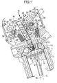
- an engine body 11 of an in-line multicylinder engine E comprises a cylinder block 13 in which cylinder bores 12 are provided, a cylinder head 14 joined to a top face of the cylinder block 13, and a head cover 15 joined to a top face of the cylinder head 14.
- Pistons 16 are slidably fitted in the cylinder bores 12.
- Combustion chambers 17 facing tops of the pistons 16 are formed between the cylinder block 13 and the cylinder head 14.
- the cylinder head 14 is equipped with intake ports 18 and exhaust ports 19 which can communicate with the combustion chambers 17. Each of the intake ports 18 is opened and closed by a pair of intake valves 20 while each of the exhaust ports 19 is opened and closed by a pair of exhaust valves 21.
- Valve springs 23 for biasing the intake valves 20 in the valve closing direction are provided between the cylinder head 14 and spring seats 22 provided at upper ends of stems 20a of the intake valves 20.
- valve springs 25 for biasing the exhaust valves 21 in the valve closing direction are provided between the cylinder head 14 and spring seats 24 provided at upper ends of stems 21a of the exhaust valves 21.
- An intake valve operating device 28 which drives the intake valves 20 for opening and closing operations includes an intake camshaft 30 having intake valve operating cams 29 in a one-to-one relationship with the cylinders, intake rocker arms 31 which swing by following the intake valve operating cams 29 and each of which is linked and connected in common to a pair of the intake valves 20 at each cylinder, and variable lift mechanisms 32 provided in a one-to-one relationship with the cylinders.
- An exhaust valve operating device 33 which drives the exhaust valves 21 for opening and closing operations includes an exhaust camshaft 35 having exhaust valve operating cams 34 in a one-to-one relationship with the cylinders, and exhaust rocker arms 36 which swing by following the exhaust valve operating cams 34 and each of which is linked and connected in common to a pair of the exhaust valves 21 at each cylinder.
- the attitude of engine body 11 is set by being inclined toward the exhaust valve operating device 33 side so that the angle ⁇ between a cylinder axis C and a vertical line VL is 20 degrees for example.
- upper holders 38 are fastened to the cylinder head 14, two upper holders 38 being disposed on opposite sides of each cylinder.
- Caps 39 and 40 forming intake cam holders 41 and exhaust cam holders 42 in association with the upper holders 38 are fastened to the upper holders 38 from above. Consequently, the intake camshaft 30 is rotatably supported between the upper holders 38 and the caps 39 forming the intake cam holders 39 while the exhaust camshaft 35 is rotatably supported between the upper holders 38 and the caps 40 forming the exhaust cam holders 42 in association with each other.
- each upper holder 38 is stepped so that the distance between the portion supporting the intake camshaft 30 and the combustion chamber 17 is larger than the distance between the portion supporting the exhaust camshaft 35 and the combustion chamber 17.
- the intake camshaft 30 is disposed higher in position than the exhaust camshaft 35 by increasing the distance between the intake camshaft 30 and the combustion chamber 17 along the cylinder axis C of the engine body 11 relative to that between the exhaust camshaft 35 and the combustion chamber 17.
- the intake camshaft 30 and the exhaust camshaft 35 are driven and rotated by motive power transmitted from a crankshaft (not shown) at a reduction ratio of 1/2.
- the direction 37 of rotation of the intake camshaft 30 is set so that the intake camshaft 30 rotates by moving upward on the side where the intake camshaft 30 faces the exhaust valve operating device 33.
- the direction of rotation of the intake camshaft 30 is indicated as a clockwise direction in FIG. 1.
- Each exhaust rocker arm 36 is swingably supported at its one end on an exhaust rocker shaft 43 having an axis parallel to the exhaust camshaft 35 and supported on the upper holder 38.
- a pair of tappet screws 44 which abut on upper ends of the stems 21a of the pair of exhaust valves 21 are screwed into the exhaust rocker arm 36 at the other end of the same so that their advance/retract positions are adjustable.
- a shaft 45 parallel to the exhaust rocker shaft 36 is provided at an intermediate portion of the exhaust rocker arm 36.
- a roller 47 which contacts the exhaust valve operating cam 34 in a rolling contact manner is axially supported on the exhaust rocker arm 36 with a roller bearing 46 interposed between the roller 47 and the shaft 45.
- This exhaust valve operating device 33 is arranged on the cylinder head 14 so that the exhaust rocker arm 36 swingably-supporting portion, i.e. , the exhaust rocker shaft 43, is placed outside the portion for linkage and connection of the exhaust rocker arm 36 to the exhaust valves 21, i.e., the tappet screws 44.
- each intake rocker arm 31 has a valve connection portion 31a provided at its one end. Tappet screws 49 which abut on upper ends of the stems 20a of the pair of intake valves 20 from above are screwed into the valve connection portion 31a so that their advance/retract positions are adjustable.
- the intake rocker arm 31 has at the other end a first supporting portion 31b and a second supporting portion 31c formed below the first supporting portion 31b continuously with the same, the first and second supporting portions 31b and 31c being formed as a generally U-shaped portion opened at the side opposite from the intake valves 20.
- a roller 50 which contacts the intake valve operating cam 29 in a rolling contact manner is axially supported on the first supporting portion 31b of the intake rocker arm 31 by means of a roller bearing 52 and a first connection shaft 51.
- the roller 50 is interposed between opposite portions of the generally U-shaped first supporting portion 31b.
- the intake rocker arm 31 is formed, for example, by die casting of a light alloy.
- a thinned portion 53 of a generally triangular shape for example is formed in a central portion of an upper surface of the valve connection portion 31a, and a pair of thinned portions 54 are formed in two portions of a lower surface of the valve connection portion 31a opposite from the upper surface in such a manner that the thinned portions 53 and 54 are alternately placed facing in opposite directions.
- the thinned portions 53 and 54 are simultaneously formed at the time of die casting of the intake rocker arm 31.
- the upper thinned portion 53 has a draft in such a direction that the opening area of the thinned portion 53 is increased with approach toward the upper surface of the valve connection portion 31a, while the lower thinned portions 54 have drafts in such directions that the opening area of the thinned portion 54 is increased with approach toward the lower surface of the valve connection portion 31a.
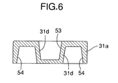
- the slanting direction of the inner surface of the thinned_portion 43 and the slanting direction of the inner surface of the thinned portions 44 are parallel to each other and wall portions 31d formed in the valve connecting portion 31a between the thinned portions 53 and 54 adjacent to each other are generally uniform in thickness.
- variable lift mechanism 32 has a first link arm 58 having one end turnably connected to the first supporting portion 31b of the intake rocker arm 31 and the other end turnably supported at a fixed position on the engine body 11 by an intake rocker shaft 5 provided as a fixed supporting shaft, a second link arm 59 having its one end turnably connected to the second supporting portion 31c of the intake rocker arm 31, a movable supporting shaft 60 which turnably supports the second link arm 59 at the other end, a control shaft 61 connected to the movable supporting shaft 60 to enable angular displacement of the movable supporting shaft 60 about an axis parallel to the axis of the movable supporting shaft 60, and an actuator motor 62 connected to the control shaft 61 to cause an angular displacement of the movable shaft 60.
- One end of the first link arm 58 is formed so as to be generally U-shaped and sandwich the first supporting portion 31b of the intake rocker arm 31 from opposite sides and is turnably connected to the first supporting portion 31b by the first connection shaft 51 that axially supports the roller 50 on the intake rocker arm 31.
- the intake rocker shaft 57 that turnably supports the other end of the first link arm 58 is supported on the upper holders 38 fastened to the cylinder head 14.
- One end of the second link arm 59 placed below the first link arm 58 is placed so as to be sandwiched in the second supporting portion 31c of the intake rocker arm 31 and is turnably connected to the second supporting portion 31c by the second connection shaft 63.
- Supporting bosses 64 are provided in the form of projections integrally on the upper holders 38 on the opposite sides of the other end of the first link arm 58 to support the intake rocker shaft 57. The movement of the intake rocker shaft 57 in the axial direction at the other end of the first link arm 58 is limited by these supporting bosses 64.
- the two intake valves 20 are biased in the valve closing direction by the valve springs 23.
- the roller 50 of the intake rocker arm 31 is maintained in contact with the intake valve operating cam 29 by the action of the valve springs 23.
- the spring force of the valve springs 23 does not act on the intake rocker arm 31 to retrain the roller 50 from moving apart from the intake valve operating cam 29.
- the intake rocker arm 31 is biased by rocker arm bias springs 65 separate from the valve springs 23 in such a direction as to be brought into abutment against the intake valve operating cam 29.
- the rocker arm bias springs 65 are coiled torsional springs surrounding the supporting bosses 64 and provided between the engine body 11 and the intake rocker arm 31. That is, ends of the rocker arm bias springs 65 engage with the supporting bosses 64 while the other ends of the rocker arm bias springs 65 are inserted in, and engage with, the first connection shaft 51 provided as a hollow shaft operating integrally with the intake rocker arm 31.
- a portion of the first link arm 58 at the other end is formed into a cylindrical shape, with its circumference placed so as to be seen inside the circumference of the rocker arm bias springs 65 wound in coil form, when laterally viewed.
- a plurality of projections e.g., a pair of projections 66 and 67, spaced circumferentially from each other, are provided to prevent the rocker arm bias springs 65 from falling toward the first link arm 58.
- the projections are kept clear of the working area of the second link arm 59, thereby maintaining the desired working area of the second link arm 59, even though the projections 66 and 67 are provided on the other end portion of the first link arm 58.
- Oil jets 68 for supplying oil toward an upper portion of the intake rocker arm 31 at the other end are mounted on the caps 39 in the intake cam holders 41 provided on the engine body 11.
- a path 69 for conducting oil from an oil pump (not shown) is provided in one of the plurality of upper holders 38.
- Circular-arc recesses 70 are formed in upper portions of the upper holders 38 so as to face the lower-half of the intake camshaft 30.
- the path 69 communicates with one of the circular-arc recesses 70.
- an oil path 71 is coaxially formed in the intake camshaft 30.
- Communication holes 72 having inner ends communicating with the oil path 71 are formed in the intake camshaft 30 at positions corresponding to the intake camholders 41 so as to have openings formed at their outer ends in the outer surface of the intake camshaft 30. Lubricating oil is supplied to the gap between the cam holders 41 and the intake camshaft 30 via the communication holes 72.
- recesses 73 are provided in lower surfaces of the caps 39 forming the intake cam holders 41 in association with the upper holders 38.
- the recesses 73 are formed as paths between the lower surfaces of the caps 39 and the upper surfaces of the upper holders 38 so as to communicate with the recesses 70.
- the oil jets 68 are mounted on the caps 39 so as to communicate with paths 74 formed in the caps 39 for communication with the recesses 73.
- the oil jets 68 are mounted on the caps 39 of the intake cam holders 46 provided on the engine body 11 so as to rotatably support the intake camshaft 30, thereby enabling a sufficient amount of oil to be supplied at a sufficiently high pressure from the oil jets 68 by using the oil paths for lubrication between the intake camshaft 30 and the intake cam holders 41.
- oil is supplied from the oil jets 68 toward the first connection shaft 51 in the upper position in the first and second connection shafts 51 and 63 by which ends of the first and second link arms 58 and 59 are connected to the intake rocker arm 31, so that the oil that has lubricated between the first link arm 58 and the intake rocker arm 31 flows down to the second link arm 59 in the lower position.
- Oil introduction holes 75 and 76 having intermediate portions facing portions of the movable supporting shaft 60 and the second connection shaft 63 are provided in the second link arm 59 in a direction perpendicular to a straight line connecting the axes of the movable supporting shaft 60, and the second connection shaft 63 and the oil introduction holes 75 and 76 have openings facing the first connection shaft 51. Therefore, the oil flowing downward from the first link ark 58 is effectively led to the gap between the second link arm 59 and the movable supporting shaft 60 and the gap between the second link arm 59 and the second connection shaft 63.
- lubrication on the intake rocker arm 31, lubrication in the connection between the first and second link arms 58 and 59 and lubrication between the second link arm 59 and the movable supporting shaft 60 can be performed by means of a simple lubrication structure having a reduced number of component parts to ensure smooth valve operations.
- the control shaft 61 is a single shaft supported on the engine body 11 as a common component associated with the plurality of cylinders arranged in-line.
- the control shaft 61 is formed into a cranked shape and has, in correspondence with each cylinder, two webs 61a placed on the opposite sides of the intake rocker arm 31, journals 61b rotatably supported on the engine body 11 and a connecting portion 61c which connects the two webs 61a.
- the movable supporting shaft 60 is connected to the control shaft 61 so as to connect each pair of webs 61a.
- Each journal 61b of the control shaft 61 is rotatably supported between the upper holder 38 connected to the cylinder head 14 of the engine body 11 and a lower holder 77 connected to the upper holder 38 from below.
- the lower holder 77 is formed separately from the cylinder head 14 and fastened to the upper holder 38.
- a recess 78 for allowing placement of the lower holder 77 is provided in the upper surface of the cylinder head 14.
- Roller bearings 79 are interposed between the upper and lower holders 38 and 77 and the journals 61b.
- the roller bearings 79 are of a bisectable type since they are interposed between the upper and lower holders 38 and 77 and the journals 61b of the control shaft 61 having the plurality of webs 61a and connecting portions 61c and provided as a common component associated with the plurality of cylinders.
- Control shaft supporting bosses 80 which project to the web 61a sides of the control shaft 61 are formed on the upper and lower holders 38 and 77 so as to pass through the journals 61a.
- camshaft supporting bosses 81 Through which the intake camshaft 30 is passed are formed so as to project toward the intake rocker arms 31.
- ribs 82 for connection between the control shaft supporting bosses 80 and the camshaft supporting bosses 81 are integrally formed so as to project therefrom.
- Paths 83 for conducting oil to the roller bearings 79 are provided in the ribs 82 to provide communication with the recesses 70 in the upper surfaces of the upper holders 38.
- the exhaust valve operating device 33 is arranged on the cylinder head 14 so that the exhaust rocker arm 36 swingably-supporting portion is placed outside the portion for linkage and connection of the exhaust rocker arm 36 to the exhaust valves 21
- the above-described intake valve operating device 28 is arranged on the cylinder head 14 so that the intake rocker shaft 57 and the movable supporting shaft 60 are placed inside the portion for linkage and connection of the intake rocker arm 31 to the intake valves 20.
- a plug cylinder 87 in which an ignition plug 86 is inserted to be mounted in the cylinder head 14 so as to face the combustion chamber 17 is provided in the cylinder head 14 between the intake valve operating device 28 and the and the exhaust valve operating device 33.
- the plug cylinder 87 is inclined by being brought closer to the exhaust valve operating device at a position closer to its upper end.
- control shaft 61 in the intake valve operating device 28 is placed between the intake valves 20 and the plug cylinders 87, with outer surfaces of the connecting portions 61c facing the plug cylinders 87. Clearance grooves 88 for avoiding interference with the plug cylinders 87 are formed in the outer surfaces of the connecting portions 61c.
- the second connection shaft 63 that connects the second link arm 59 to the intake rocker arm 31 is coaxial with the journals 61b of the control shaft 61.
- the control shaft 61 swings about the axis of the journals 61b, the movable supporting shaft 60 moves on a circular arc of a circle the center of which corresponds to the axis of the journals.
- one of the journals 61b of the control shaft 61 sticks out from a support hole 89 provided in the head cover 15.
- a control arm 91 is fixed to the tip of the journal 61b and driven by the actuator motor 62 mounted on an outer wall of the cylinder head 14. That is, a nut member 93 meshes with a threaded shaft 92 rotated by the actuator motor 62, and a connecting link 95 having its one end pivotally supported by a pin 94 is connected at the other end to the control arm 91 by pins 96.
- a rotational angle sensor 97 such as a rotary encoder is installed on an outer wall surface of the head cover 15 with one end of a sensor arm 98 fixed to the tip of a sensor shaft 97a.
- a guide groove 99 is formed in the control arm 91 so as to extend linearly in the lengthwise direction of the control arm 91, and a connecting shaft 100 mounted on the other end of the sensor arm 98 is slidably fitted in the guide groove 99.
- the threaded shaft 92, nut member 93, pin 94, connecting link 95, pins 96, control arm 91, rotational angle sensor 97, sensor arm 98, and connecting shaft 100 are housed in a case 101 mounted on side surfaces of the cylinder head 14 and the head cover 15 with bolts 102.
- a cover 103 which covers open end faces of the case 101 is mounted on the case 101 by with screw members 104.
- variable lift mechanism 32 when the control arm 91 is turned counterclockwise by the actuator motor 62 from the position indicated in FIG. 9, the control shaft 61 connected to the control arm 91 also turns counterclockwise to move the movable supporting shaft 60 downward.
- the intake valve operating cam 29 on the intake camshaft 30 pushes the roller 50 in this state, a four-bar link joining the intake rocker shaft 57, the first connection shaft 51, the second connection shaft 63 and the movable supporting shaft 60 deforms and causes the intake rocker arms 31 to swing downward.
- the tappet screws 49 thereby push the stems 20a of the intake valves 20, finally opening the intake valves 20 with a low lift.
- the intake camshaft 30 is placed higher in position than the exhaust camshaft 35 by increasing the distance between the intake camshaft 30 and the combustion chamber 17 along the cylinder axis C of the engine body 11 relative to that between the exhaust camshaft 35 and the combustion chamber 17, thereby making it easier to cause lubricating oil to flow to the exhaust valve operating device 33 after lubrication and cooling of the intake valve operating device 28 maintained at a comparatively low temperature, and making it possible to efficiently lubricate and cool the exhaust valve operating device 33 under thermally severe conditions.
- the intake valve operating device 28 has the variable lift mechanism 32 capable of changing the valve opening lift of the intake valve 20, and the exhaust valve operating device 33 has the exhaust camshaft 35 and the exhaust rocker arm 36 linked and connected to the exhaust valves 21 so as to be able to swing by following the exhaust camshaft 35.
- the lift of the intake valves 20 is changed by the variable lift mechanism 32. In this way, the amount of air intake can be controlled without using the throttle valve.
- the variable lift mechanism 32 can be effectively arranged in a space on the intake valve operating device 28 side where there is room larger than that on the exhaust valve operating device 33 side.
- the attitude of engine body 11 is set so that the cylinder axis C is inclined toward the exhaust valve operating device 33. Therefore, lubricating oil flows efficiently to the exhaust valve operating device 33 after lubricating and cooling the intake valve operating device 28. Thus, lubrication and cooling of the exhaust valve operating device 33 can performed more efficiently.
- the direction 37 of rotation of the intake camshaft 30 is set so that the intake camshaft 30 rotates by moving upward on the side where the intake camshaft 30 faces the exhaust valve operating device 33.
- An upward splash of the lubricating oil toward the exhaust valve operating device 33 is caused by this rotation of the intake camshaft 30 to more efficiently lubricate and cool the exhaust valve operating device 33.
- variable lift mechanism 32 for continuously changing the valve opening lift of the intake valves ends of the first and second link arms 58 and 59 are connected relatively movably in parallel wit each other to the intake rocker arm 31 having valve connection portion 31a linked and connected to the pair of intake valves 20, the other end of the first link arm 58 is turnably supported by the intake rocker shaft 57 supported on the engine body 11, and the other end of the second link arm 59 is turnably supported by the movable supporting shaft 60 capable of being displaced.
- the lift of the intake valves 20 can be steplessly changed by steplessly displacing the movable supporting shaft 60.
- ends of the first and second link arms 58 and 59 are turnably connected directly to the intake rocker arm 31, so that the space in which the two link arms 58 and 59 are disposed is reduced, thus making the valve operating device compact.
- motive power is directly transmitted from the intake valve operating cam 29 to the roller 50 of the intake rocker arm 31, improved followability to the intake valve operating cam 29 can be ensured.
- the intake rocker arm 31 and the first and second link arms 58 and 59 can be disposed at substantially the same position in the direction along the axis of the intake camshaft 30, thereby making the intake valve operating device 28 compact in the direction along the intake camshaft 30.
- One end of the first link arm 58 is turnably connected to the intake rocker arm 31 by the first connection shaft 51, and the roller 50 is axially supported on the intake rocker arm 31 by the first connection shaft 51. That is, connection of one end of the first link arm 58 to the intake rocker arm 31 allowing rotation of the first link arm 58 and axial support of the roller 50 on the intake rocker arm 31 are achieved by means of the first connection shaft 51, thus reducing the number of component parts and making the intake valve operating device 28 more compact.
- the intake rocker shaft 57 and the movable supporting shaft 60 are placed inside the portion for linkage and connection of the intake rocker arm 31 to the intake valves 20, while the portion of the exhaust valve operating device 33 for swingably supporting the exhaust rocker arm 36 is placed outside the portion for linkage and connection of the exhaust rocker arm 36 to the exhaust valves 21. It is, therefore, possible to avoid mutual interference between the intake valve operating device 28 and the exhaust valve operating device 33 while avoiding an increase in size of the cylinder head 14 even in a case where the angle ⁇ contained between the intake valves 20 and the exhaust valves 21 (see FIG. 1) is set small in order to reduce the size of the combustion chamber 17 to obtain good combustion.
- the exhaust valve operating device 33 has the exhaust camshaft 35 having the exhaust valve operating cams 34, and the exhaust rocker arms 36 swingably supported on the engine body 11 by the exhaust rocker shaft 43 to swing by following the exhaust valve operating cam 35 and linked and connected to the exhaust valves 21.
- the plug cylinder 68 placed between the intake valve operating device 28 and the exhaust valve operating device 33 is mounted in the cylinder head 14 by being inclined so as to be brought closer to the exhaust valve operating device 33 at a position closer to its upper end.
- the plug cylinder 68 is placed so as to avoid interference with the intake valve operating device 28 and the exhaust valve operating device 33. This placement contributes to the effect of making the entire cylinder head 14 more compact.
- the control shaft 61 provided in the variable link mechanism 32 of the intake valve operating device 28 is connected to the movable supporting shaft 60 to enable angular displacement of the movable supporting shaft 60 about an axis parallel to the axis of the movable supporting shaft 60 and is supported on the engine body 11 on the opposite sides of the intake rocker arm 31.
- the rigidity of the support for the control shaft 61 is increased by adopting the dual-support structure to enable variable-lift control on the intake valves 20 to be performed with accuracy.
- the above-described single control shaft 61 is supported on the engine body 11 as a common component associated with the plurality of cylinders arranged in-line. It is, therefore, possible to make the engine E compact by avoiding increasing the number of component parts.
- control shaft 61 is formed into a cranked shape and has the two webs 61a placed on the opposite sides of the intake rocker arm 31, the journals 61b joined perpendicularly to outer surfaces of base end portions of the two webs 61a and turnably supported on the engine body 11, and the connecting portion 61C that connects the two webs 61a.
- the movable supporting shaft 60 is connected to the control shaft 61 so as to connect the two webs 61. Therefore, the rigidity of the control shaft 61 driven to be angularly displaced can be increased.
- the journals 61b of the control shaft 61 are rotatably supported between the upper holders 38 connected to the cylinder head 14 of the engine body 11 and the lower holders 77 connected to the upper holders 38 from below.
- the facility with which the control shaft 61 is mounted to the engine body 11 can be improved.
- the lower holders 77 separate from the cylinder head 14 is fastened to the upper holders 38, the degree of freedom with which the cylinder head 14 is designed with respect to support for the control shaft 61 can be increased.
- the bisectable roller bearings 79 are interposed between the upper and lower holders 38 and 77 and the journals 61b to improve the facility with which the control shaft 61 is mounted to the engine body 11 while reducing the loss due to friction at the portions supporting the control shaft 61.
- control shaft supporting bosses 80 projecting to the sides of the webs 61a of the control shaft 61 are formed on the upper and lower holders 38 and 77 connected to each other, and the journals 61b passed through the control shaft supporting bosses 80 are turnably supported between the upper and lower holders 38 and 77. Therefore, the rigidity of the support for the control shaft 61 can be further increased.
- the camshaft supporting bosses 81 projecting toward the intake rocker arm 31 are formed on the upper holders 38 and the caps 39 connected to the upper holders 38 from above.
- the intake camshaft 30 is passed through the camshaft supporting bosses 81 and rotatably supported between the upper holders 38 and the caps 39. It is, therefore, possible to increase the rigidity of the support for the intake camshaft 30 while minimizing the number of component parts for supporting the intake camshaft 30.
- the ribs 82 for connection between the control shaft supporting bosses 80 and the camshaft supporting bosses 81 are formed on the upper holders 38 so as to project from the same to further increase the rigidity of the supports for the control shaft 61 and the intake camshaft 30.
- the control shaft 61 is placed between the intake valves 20 and the plug cylinders 87 provided in the cylinder head 14, with the outer surfaces of the connecting portions 61c facing the plug cylinders 87.
- the clearance grooves 88 for avoiding interference with the plug cylinders 87 are formed in the outer surfaces of the connecting portions 61c. Therefore, the plug cylinders 87 can be placed closer to the intake valve operating device 28 to make the engine E compact.
- the intake rocker arm 31 of the intake valve operating device 28 has thinned portions 53 and 54 formed in surfaces of the valve connecting portion 61a opposite from each other, the thinned portions 53 and 54 being alternately placed facing in opposite directions. Therefore, the intake rocker arm 31 can be reduced in weight.
- the thinned portions 53 and 54 are simultaneously formed at the time of die casting of the intake rocker arm 31.
- Each of the adjacent pairs of the thinned portions 53 and 54 have drafts in directions reverse to each other, such that the inner surfaces of the adjacent pair of the thinned portions 53 and 54 are inclined in the same direction. Therefore, the wall portions 31d formed in the intake rocker arm 31 between the thinned portions 53 and 54 adjacent to each other are generally uniform in thickness.
- the desired rigidity of the intake rocker arm 31 can be maintained by forming the wall portions 31d generally uniform in thickness.
- the intake valve operating device 28 has the variable lift mechanism 32 capable of steplessly changing the lift of the intake valves 20. Therefore, the number of component parts in the intake valve operating device 28 is comparatively large. Even in the intake valve operating device 28 having the variable lift mechanism 32 liable to be a cause of an increase in weight of the intake valve operating device 28, the weight of the intake valve operating device 28 can be reduced by reducing the weight of the intake rocker arm 31, thereby increasing the critical rotational speed.
- the embodiment has been described with respect to a case where the plug cylinder 87 is placed between the intake valve operating device 28 and the exhaust valve operating device 33, the present invention can also be applied to an engine in which a fuel injection valve for directly injecting fuel into the combustion chamber 17 is placed between the intake valve operating device 28 and the exhaust valve operating device 33.
Abstract
Description
- The present invention relates to an engine in which an intake valve driven for opening and closing operations by an intake valve operating device having an intake camshaft and an exhaust valve driven for opening and closing operations by an exhaust valve operating device having an exhaust camshaft are provided in a cylinder head forming a portion of an engine body.
- Such engine is known from Patent Document 1, for example. Patent Document 1:
-
Japanese Patent Application Laid-open No. 2004-52708 - Lubrication and cooling of an exhaust valve operating device must be performed under thermally severe conditions in comparison with lubrication and cooling of an intake valve operating device. If lubricating oil can be used for an exhaust valve operating device after being used for lubrication and cooling of an intake valve operating device at a comparatively low temperature, lubrication and cooling of the exhaust valve operating device can be efficiently performed. In the engine disclosed in the above-described
Japanese Patent Application Laid-open No. 2004-52708 - In view of the above-described circumstances, an object of the present invention is to provide an engine in which lubricating oil can be easily used for an exhaust valve operating device after being used for lubrication and cooling of an intake valve operating device to enable lubrication and cooling of the exhaust valve operating device with efficiency.
- To achieve the above-described object, according to a first feature of the present invention, there is provided an engine having a cylinder head which forms a portion of an engine body and is provided with an intake valve driven for opening and closing operations by an intake valve operating device having an intake camshaft and an exhaust valve driven for opening and closing operations by an intake valve operating device having an exhaust camshaft, characterized in that the intake camshaft is placed higher in position than the exhaust camshaft by increasing the distance between the intake camshaft and a combustion chamber along a cylinder axis of the engine body relative to the distance between the exhaust camshaft and the combustion chamber.
- According to a second feature of the present invention in addition to the arrangement of the first feature, there is provided an engine, wherein the intake valve operating device has a variable lift mechanism capable of changing the valve opening lift amount of the intake valve, and the exhaust valve operating device has the exhaust camshaft and an exhaust rocker arm linked and connected to the exhaust valve so as to swing by following the exhaust camshaft.
- According to a third feature of the present invention in addition to the arrangement of the first feature, there is provided an engine, wherein the engine body is placed in an attitude such that the cylinder axis is inclined toward the exhaust valve operating device.
- According to a fourth feature of the present invention in addition to the arrangement of the first feature, there is provided an engine, wherein the direction of rotation of the intake camshaft is set so that the intake camshaft rotates by moving upward on the side where the intake camshaft faces the exhaust valve operating device.
- According to a fifth feature of the present invention in addition to the arrangement of the second feature, there is provided an engine, wherein the intake valve operating device includes the intake camshaft having an intake valve operating cam, an intake rocker arm having a cam contact portion which contacts the intake valve operating cam, the intake rocker arm being liked and connected to the intake valve so as to apply a force to the intake valve in the valve opening direction, and the variable lift mechanism, and the variable lift mechanism has a first link arm having one end thereof turnably connected to the intake rocker arm and the other end turnably supported at a fixed position on the engine body through a fixed supporting shaft, and a second link arm having one end thereof turnably connected to the intake rocker arm and the other end turnably supported on a movable supporting shaft capable of being displaced.
- According to a sixth feature of the present invention in addition to the arrangement according to the fifth feature, there is provided an engine, wherein the fixed supporting shaft and the movable supporting shaft are placed inside a portion for linkage and connection of the intake rocker arm to the intake valve, and a portion of the exhaust valve operating device for swingably supporting the exhaust rocker arm is placed outside a portion for linkage and connection of the exhaust rocker arm and the exhaust valve.
- According to a seventh feature of the present invention in addition to the arrangement according to the sixth feature, there is provided an engine, wherein a plug cylinder inclined so as to be brought closer to the exhaust valve operating device at a position closer to an upper end thereof is mounted in the cylinder head by being placed between the intake valve operating device and the exhaust valve operating device.
- According to the first feature of the present invention, the intake camshaft is higher in position than the exhaust camshaft. Therefore, lubricating oil can be easily caused to flow to the exhaust valve operating device after lubricating and cooling the intake valve operating device at a comparatively low temperature, thus achieving efficient lubrication and cooling of the exhaust valve operating device under thermally severe conditions.
- According to the second feature of the present invention, the lift of the intake valve is changed by the variable lift mechanism, thus enabling control of the amount of air intake without using the throttle valve. Moreover, the variable lift mechanism can be effectively arranged in a space on the intake valve operating device side where there is room larger than that on the exhaust valve operating device side.
- According to the third feature of the present invention, the cylinder axis of the engine body is inclined toward the exhaust valve operating device, so that lubricating oil flows more smoothly to the exhaust valve operating device after lubricating and cooling the intake valve operating device, thus achieving more efficient lubrication and cooling of the exhaust valve operating device.
- According to the fourth feature of the present invention, an upward splash of the lubricating oil toward the exhaust valve operating device is caused by the rotation of the intake camshaft to more efficiently lubricate and cool the exhaust valve operating device.
- According to the fifth feature of the present invention, ends of the first and second link arms forming the variable lift mechanism are turnably connected directly to the rocker arm, so that the space in which the two link arms are disposed is reduced, thus making the valve operating device compact. Since motive power is directly transmitted from the intake valve operating cam to the cam contact portion of the intake rocker arm, improved followability to the valve operating cam can be ensured.
- According to the sixth feature of the present invention, the fixed supporting shaft and the movable supporting shaft of the first and second link arms are placed inside a portion for linkage and connection of the intake rocker arm and the intake valve, and a portion of the exhaust valve operating device for swingably supporting the exhaust rocker arm is placed outside a portion for linkage and connection of the exhaust rocker arm and the exhaust valve. It is, therefore, possible to avoid mutual interference between the intake valve operating device and the exhaust valve operating device while avoiding an increase in size of the cylinder head even in a case where the angle contained between the intake valve and the exhaust valve is set small.
- According to the seventh feature of the present invention, the plug cylinder is placed so as to avoid interference with the intake valve operating device and the exhaust valve operating device. This placement contributes to the effect of making the entire cylinder head more compact.
-
- [FIG.1] FIG.1 is a partial longitudinal sectional view of an engine according to an embodiment of the present invention taken along line 1-1 of FIG. 2. (Embodiment 1)
- [FIG.2] FIG. 2 is a sectional view taken along line 2-2 of FIG. 1. (Embodiment 1)
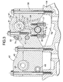
- [FIG.3] FIG. 3 is a sectional view taken along line 3-3 of FIG. 2. (Embodiment 1)
- [FIG.4] FIG. 4 is an enlarged view of an essential portion of FIG. 1. (Embodiment 1)
- [FIG.5] FIG. 5 is a bottom view of an intake rocker arm seen in the direction of arrow 5 in FIG. 4. (Embodiment 1)
- [FIG.6] FIG. 6 is a sectional view taken along line 6-6 of FIG. 4. (Embodiment 1)
- [FIG. 7] FIG. 7 is a perspective view of a variable lif t mechanism . (Embodiment 1)
- [FIG.8] FIG. 8 is a sectional view taken along line 8-8 of FIG. 4. (Embodiment 1)
- [FIG.9] FIG. 9 is a sectional view taken along line 9-9 of FIG. 2. (Embodiment 1)
- [FIG.10] FIG. 10 is a perspective view seen in the direction of
arrow 10 in FIG. 9. (Embodiment 1) -
- 11 ···
- engine body
- 14 ···
- cylinder head
- 17 ···
- combustion chamber
- 20 ···
- intake valve
- 21 ···
- exhaust valve
- 28 ···
- intake valve operating device
- 29 ···
- intake valve operating cam
- 31 ···
- intake rocker arm
- 32 ···
- variable lift mechanism
- 33 ···
- exhaust valve operating device
- 34 ···
- exhaust valve operating cam
- 35 ···
- exhaust camshaft
- 36 ···
- exhaust rocker arm
- 37 ···
- direction of rotation
- 39 ···
- intake cam
- 43 ···
- exhaust rocker shaft
- 50 ···
- roller as a cam contact portion
- 57 ···
- intake rocker shaft as a fixed supporting shaft
- 58 ···
- first link arm
- 59 ···
- second link arm
- 60 ···
- movable supporting shaft
- 87 ···
- plug cylinder
- C ···
- cylinder axis
- E ···
- engine
- A mode for carrying out the present invention will be described by way of one embodiment of the present invention with reference to the accompanying drawings.
- FIGS. 1 through 10 show one embodiment of the present invention.
- Referring to FIG. 1, an
engine body 11 of an in-line multicylinder engine E comprises acylinder block 13 in which cylinder bores 12 are provided, acylinder head 14 joined to a top face of thecylinder block 13, and ahead cover 15 joined to a top face of thecylinder head 14.Pistons 16 are slidably fitted in the cylinder bores 12. Combustion chambers 17 facing tops of thepistons 16 are formed between thecylinder block 13 and thecylinder head 14. - The
cylinder head 14 is equipped withintake ports 18 and exhaust ports 19 which can communicate with the combustion chambers 17. Each of theintake ports 18 is opened and closed by a pair ofintake valves 20 while each of the exhaust ports 19 is opened and closed by a pair ofexhaust valves 21. Valve springs 23 for biasing theintake valves 20 in the valve closing direction are provided between thecylinder head 14 andspring seats 22 provided at upper ends ofstems 20a of theintake valves 20. Also, valve springs 25 for biasing theexhaust valves 21 in the valve closing direction are provided between thecylinder head 14 andspring seats 24 provided at upper ends ofstems 21a of theexhaust valves 21. - An intake
valve operating device 28 which drives theintake valves 20 for opening and closing operations includes anintake camshaft 30 having intakevalve operating cams 29 in a one-to-one relationship with the cylinders,intake rocker arms 31 which swing by following the intakevalve operating cams 29 and each of which is linked and connected in common to a pair of theintake valves 20 at each cylinder, andvariable lift mechanisms 32 provided in a one-to-one relationship with the cylinders. An exhaustvalve operating device 33 which drives theexhaust valves 21 for opening and closing operations includes anexhaust camshaft 35 having exhaustvalve operating cams 34 in a one-to-one relationship with the cylinders, andexhaust rocker arms 36 which swing by following the exhaustvalve operating cams 34 and each of which is linked and connected in common to a pair of theexhaust valves 21 at each cylinder. - The attitude of
engine body 11 is set by being inclined toward the exhaustvalve operating device 33 side so that the angle θ between a cylinder axis C and a vertical line VL is 20 degrees for example. - Referring also to FIGS. 2 and 3,
upper holders 38 are fastened to thecylinder head 14, twoupper holders 38 being disposed on opposite sides of each cylinder.Caps intake cam holders 41 andexhaust cam holders 42 in association with theupper holders 38 are fastened to theupper holders 38 from above. Consequently, theintake camshaft 30 is rotatably supported between theupper holders 38 and thecaps 39 forming theintake cam holders 39 while theexhaust camshaft 35 is rotatably supported between theupper holders 38 and thecaps 40 forming theexhaust cam holders 42 in association with each other. - The upper surface of each
upper holder 38 is stepped so that the distance between the portion supporting theintake camshaft 30 and the combustion chamber 17 is larger than the distance between the portion supporting theexhaust camshaft 35 and the combustion chamber 17. Thus, theintake camshaft 30 is disposed higher in position than theexhaust camshaft 35 by increasing the distance between theintake camshaft 30 and the combustion chamber 17 along the cylinder axis C of theengine body 11 relative to that between theexhaust camshaft 35 and the combustion chamber 17. - The
intake camshaft 30 and theexhaust camshaft 35 are driven and rotated by motive power transmitted from a crankshaft (not shown) at a reduction ratio of 1/2. Thedirection 37 of rotation of theintake camshaft 30 is set so that theintake camshaft 30 rotates by moving upward on the side where theintake camshaft 30 faces the exhaustvalve operating device 33. The direction of rotation of theintake camshaft 30 is indicated as a clockwise direction in FIG. 1. - Each
exhaust rocker arm 36 is swingably supported at its one end on anexhaust rocker shaft 43 having an axis parallel to theexhaust camshaft 35 and supported on theupper holder 38. A pair of tappet screws 44 which abut on upper ends of thestems 21a of the pair ofexhaust valves 21 are screwed into theexhaust rocker arm 36 at the other end of the same so that their advance/retract positions are adjustable. Ashaft 45 parallel to theexhaust rocker shaft 36 is provided at an intermediate portion of theexhaust rocker arm 36. Aroller 47 which contacts the exhaustvalve operating cam 34 in a rolling contact manner is axially supported on theexhaust rocker arm 36 with aroller bearing 46 interposed between theroller 47 and theshaft 45. - This exhaust
valve operating device 33 is arranged on thecylinder head 14 so that theexhaust rocker arm 36 swingably-supporting portion, i.e. , theexhaust rocker shaft 43, is placed outside the portion for linkage and connection of theexhaust rocker arm 36 to theexhaust valves 21, i.e., the tappet screws 44. - Referring to FIGS. 4 and 5, each
intake rocker arm 31 has avalve connection portion 31a provided at its one end. Tappet screws 49 which abut on upper ends of thestems 20a of the pair ofintake valves 20 from above are screwed into thevalve connection portion 31a so that their advance/retract positions are adjustable. Theintake rocker arm 31 has at the other end a first supportingportion 31b and a second supportingportion 31c formed below the first supportingportion 31b continuously with the same, the first and second supportingportions intake valves 20. - A
roller 50 which contacts the intakevalve operating cam 29 in a rolling contact manner is axially supported on the first supportingportion 31b of theintake rocker arm 31 by means of aroller bearing 52 and afirst connection shaft 51. Theroller 50 is interposed between opposite portions of the generally U-shaped first supportingportion 31b. - Referring also to FIG. 6, the
intake rocker arm 31 is formed, for example, by die casting of a light alloy. A thinnedportion 53 of a generally triangular shape for example is formed in a central portion of an upper surface of thevalve connection portion 31a, and a pair of thinnedportions 54 are formed in two portions of a lower surface of thevalve connection portion 31a opposite from the upper surface in such a manner that the thinnedportions - The thinned
portions intake rocker arm 31. The upper thinnedportion 53 has a draft in such a direction that the opening area of the thinnedportion 53 is increased with approach toward the upper surface of thevalve connection portion 31a, while the lower thinnedportions 54 have drafts in such directions that the opening area of the thinnedportion 54 is increased with approach toward the lower surface of thevalve connection portion 31a. Accordingly, the slanting direction of the inner surface of thethinned_portion 43 and the slanting direction of the inner surface of the thinnedportions 44 are parallel to each other andwall portions 31d formed in thevalve connecting portion 31a between the thinnedportions - Referring also to FIGS. 7 and 8, the
variable lift mechanism 32 has afirst link arm 58 having one end turnably connected to the first supportingportion 31b of theintake rocker arm 31 and the other end turnably supported at a fixed position on theengine body 11 by an intake rocker shaft 5 provided as a fixed supporting shaft, asecond link arm 59 having its one end turnably connected to the second supportingportion 31c of theintake rocker arm 31, a movable supportingshaft 60 which turnably supports thesecond link arm 59 at the other end, acontrol shaft 61 connected to the movable supportingshaft 60 to enable angular displacement of the movable supportingshaft 60 about an axis parallel to the axis of the movable supportingshaft 60, and anactuator motor 62 connected to thecontrol shaft 61 to cause an angular displacement of themovable shaft 60. - One end of the
first link arm 58 is formed so as to be generally U-shaped and sandwich the first supportingportion 31b of theintake rocker arm 31 from opposite sides and is turnably connected to the first supportingportion 31b by thefirst connection shaft 51 that axially supports theroller 50 on theintake rocker arm 31. Theintake rocker shaft 57 that turnably supports the other end of thefirst link arm 58 is supported on theupper holders 38 fastened to thecylinder head 14. - One end of the
second link arm 59 placed below thefirst link arm 58 is placed so as to be sandwiched in the second supportingportion 31c of theintake rocker arm 31 and is turnably connected to the second supportingportion 31c by thesecond connection shaft 63. - Supporting
bosses 64 are provided in the form of projections integrally on theupper holders 38 on the opposite sides of the other end of thefirst link arm 58 to support theintake rocker shaft 57. The movement of theintake rocker shaft 57 in the axial direction at the other end of thefirst link arm 58 is limited by these supportingbosses 64. - The two
intake valves 20 are biased in the valve closing direction by the valve springs 23. When the twointake valves 20 spring-biased in the valve closing direction are driven in the valve opening direction by theintake rocker arm 31, theroller 50 of theintake rocker arm 31 is maintained in contact with the intakevalve operating cam 29 by the action of the valve springs 23. However, when theintake valves 20 are in the closing state, the spring force of the valve springs 23 does not act on theintake rocker arm 31 to retrain theroller 50 from moving apart from the intakevalve operating cam 29. There is a possibility of the valve lift control accuracy being reduced when theintake valves 20 are slightly opened. Therefore, theintake rocker arm 31 is biased by rocker arm bias springs 65 separate from the valve springs 23 in such a direction as to be brought into abutment against the intakevalve operating cam 29. - The rocker arm bias springs 65 are coiled torsional springs surrounding the supporting
bosses 64 and provided between theengine body 11 and theintake rocker arm 31. That is, ends of the rocker arm bias springs 65 engage with the supportingbosses 64 while the other ends of the rocker arm bias springs 65 are inserted in, and engage with, thefirst connection shaft 51 provided as a hollow shaft operating integrally with theintake rocker arm 31. - A portion of the
first link arm 58 at the other end is formed into a cylindrical shape, with its circumference placed so as to be seen inside the circumference of the rocker arm bias springs 65 wound in coil form, when laterally viewed. At axially opposite ends of the other end portion of thefirst link arm 58, a plurality of projections, e.g., a pair ofprojections first link arm 58. Thus, while increasing the size of the other end portion of thefirst link arm 58 is avoided, the above-described falling of the rocker arm bias springs 65 can be prevented and the supporting rigidity of the other end portion of thefirst link arm 58 can be increased. - The projections are kept clear of the working area of the
second link arm 59, thereby maintaining the desired working area of thesecond link arm 59, even though theprojections first link arm 58. -
Oil jets 68 for supplying oil toward an upper portion of theintake rocker arm 31 at the other end are mounted on thecaps 39 in theintake cam holders 41 provided on theengine body 11. - A
path 69 for conducting oil from an oil pump (not shown) is provided in one of the plurality ofupper holders 38. Circular-arc recesses 70 are formed in upper portions of theupper holders 38 so as to face the lower-half of theintake camshaft 30. Thepath 69 communicates with one of the circular-arc recesses 70. On the other hand, an oil path 71 is coaxially formed in theintake camshaft 30. Communication holes 72 having inner ends communicating with the oil path 71 are formed in theintake camshaft 30 at positions corresponding to theintake camholders 41 so as to have openings formed at their outer ends in the outer surface of theintake camshaft 30. Lubricating oil is supplied to the gap between thecam holders 41 and theintake camshaft 30 via the communication holes 72. - Also, recesses 73 are provided in lower surfaces of the
caps 39 forming theintake cam holders 41 in association with theupper holders 38. Therecesses 73 are formed as paths between the lower surfaces of thecaps 39 and the upper surfaces of theupper holders 38 so as to communicate with therecesses 70. Theoil jets 68 are mounted on thecaps 39 so as to communicate withpaths 74 formed in thecaps 39 for communication with therecesses 73. - Thus, the
oil jets 68 are mounted on thecaps 39 of theintake cam holders 46 provided on theengine body 11 so as to rotatably support theintake camshaft 30, thereby enabling a sufficient amount of oil to be supplied at a sufficiently high pressure from theoil jets 68 by using the oil paths for lubrication between theintake camshaft 30 and theintake cam holders 41. - Also, oil is supplied from the
oil jets 68 toward thefirst connection shaft 51 in the upper position in the first andsecond connection shafts second link arms intake rocker arm 31, so that the oil that has lubricated between thefirst link arm 58 and theintake rocker arm 31 flows down to thesecond link arm 59 in the lower position. - Oil introduction holes 75 and 76 having intermediate portions facing portions of the movable supporting
shaft 60 and thesecond connection shaft 63 are provided in thesecond link arm 59 in a direction perpendicular to a straight line connecting the axes of the movable supportingshaft 60, and thesecond connection shaft 63 and the oil introduction holes 75 and 76 have openings facing thefirst connection shaft 51. Therefore, the oil flowing downward from thefirst link ark 58 is effectively led to the gap between thesecond link arm 59 and the movable supportingshaft 60 and the gap between thesecond link arm 59 and thesecond connection shaft 63. Thus, lubrication on theintake rocker arm 31, lubrication in the connection between the first andsecond link arms second link arm 59 and the movable supportingshaft 60 can be performed by means of a simple lubrication structure having a reduced number of component parts to ensure smooth valve operations. - The
control shaft 61 is a single shaft supported on theengine body 11 as a common component associated with the plurality of cylinders arranged in-line. Thecontrol shaft 61 is formed into a cranked shape and has, in correspondence with each cylinder, twowebs 61a placed on the opposite sides of theintake rocker arm 31,journals 61b rotatably supported on theengine body 11 and a connectingportion 61c which connects the twowebs 61a. The movable supportingshaft 60 is connected to thecontrol shaft 61 so as to connect each pair ofwebs 61a. - Each
journal 61b of thecontrol shaft 61 is rotatably supported between theupper holder 38 connected to thecylinder head 14 of theengine body 11 and alower holder 77 connected to theupper holder 38 from below. Thelower holder 77 is formed separately from thecylinder head 14 and fastened to theupper holder 38. Arecess 78 for allowing placement of thelower holder 77 is provided in the upper surface of thecylinder head 14. -
Roller bearings 79 are interposed between the upper andlower holders journals 61b. Theroller bearings 79 are of a bisectable type since they are interposed between the upper andlower holders journals 61b of thecontrol shaft 61 having the plurality ofwebs 61a and connectingportions 61c and provided as a common component associated with the plurality of cylinders. - Control
shaft supporting bosses 80 which project to theweb 61a sides of thecontrol shaft 61 are formed on the upper andlower holders journals 61a. On theupper holders 38 and thecaps 39 connected to each other to form theintake cam holders 41 in association with each other,camshaft supporting bosses 81 through which theintake camshaft 30 is passed are formed so as to project toward theintake rocker arms 31. On theupper holders 38,ribs 82 for connection between the controlshaft supporting bosses 80 and thecamshaft supporting bosses 81 are integrally formed so as to project therefrom. -
Paths 83 for conducting oil to theroller bearings 79 are provided in theribs 82 to provide communication with therecesses 70 in the upper surfaces of theupper holders 38. - While the exhaust
valve operating device 33 is arranged on thecylinder head 14 so that theexhaust rocker arm 36 swingably-supporting portion is placed outside the portion for linkage and connection of theexhaust rocker arm 36 to theexhaust valves 21, the above-described intakevalve operating device 28 is arranged on thecylinder head 14 so that theintake rocker shaft 57 and the movable supportingshaft 60 are placed inside the portion for linkage and connection of theintake rocker arm 31 to theintake valves 20. - Further, a
plug cylinder 87 in which anignition plug 86 is inserted to be mounted in thecylinder head 14 so as to face the combustion chamber 17 is provided in thecylinder head 14 between the intakevalve operating device 28 and the and the exhaustvalve operating device 33. Theplug cylinder 87 is inclined by being brought closer to the exhaust valve operating device at a position closer to its upper end. - Thus, the
control shaft 61 in the intakevalve operating device 28 is placed between theintake valves 20 and theplug cylinders 87, with outer surfaces of the connectingportions 61c facing theplug cylinders 87.Clearance grooves 88 for avoiding interference with theplug cylinders 87 are formed in the outer surfaces of the connectingportions 61c. - When the
intake valves 20 are in the closing state, thesecond connection shaft 63 that connects thesecond link arm 59 to theintake rocker arm 31 is coaxial with thejournals 61b of thecontrol shaft 61. When thecontrol shaft 61 swings about the axis of thejournals 61b, the movable supportingshaft 60 moves on a circular arc of a circle the center of which corresponds to the axis of the journals. - Referring to FIGS. 9 and 10, one of the
journals 61b of thecontrol shaft 61 sticks out from asupport hole 89 provided in thehead cover 15. Acontrol arm 91 is fixed to the tip of thejournal 61b and driven by theactuator motor 62 mounted on an outer wall of thecylinder head 14. That is, anut member 93 meshes with a threadedshaft 92 rotated by theactuator motor 62, and a connectinglink 95 having its one end pivotally supported by apin 94 is connected at the other end to thecontrol arm 91 bypins 96. Therefore, when theactuator motor 62 is made to operate, thenut member 93 moves along the rotating threadedshaft 92, and thecontrol shaft 61 is caused to swing around thejournal 61b by thecontrol arm 91 connected to thenut member 93 by the connectinglink 95, thereby causing a displacement of the movable supportingshaft 60. - A
rotational angle sensor 97 such as a rotary encoder is installed on an outer wall surface of thehead cover 15 with one end of asensor arm 98 fixed to the tip of asensor shaft 97a. Aguide groove 99 is formed in thecontrol arm 91 so as to extend linearly in the lengthwise direction of thecontrol arm 91, and a connectingshaft 100 mounted on the other end of thesensor arm 98 is slidably fitted in theguide groove 99. - The threaded
shaft 92,nut member 93,pin 94, connectinglink 95, pins 96,control arm 91,rotational angle sensor 97,sensor arm 98, and connectingshaft 100 are housed in acase 101 mounted on side surfaces of thecylinder head 14 and thehead cover 15 withbolts 102. Acover 103 which covers open end faces of thecase 101 is mounted on thecase 101 by withscrew members 104. - In the
variable lift mechanism 32, when thecontrol arm 91 is turned counterclockwise by theactuator motor 62 from the position indicated in FIG. 9, thecontrol shaft 61 connected to thecontrol arm 91 also turns counterclockwise to move the movable supportingshaft 60 downward. When the intakevalve operating cam 29 on theintake camshaft 30 pushes theroller 50 in this state, a four-bar link joining theintake rocker shaft 57, thefirst connection shaft 51, thesecond connection shaft 63 and the movable supportingshaft 60 deforms and causes theintake rocker arms 31 to swing downward. The tappet screws 49 thereby push thestems 20a of theintake valves 20, finally opening theintake valves 20 with a low lift. - When the
control arm 91 is turned to the solid-line position in FIG. 9 by theactuator motor 62, thecontrol shaft 61 connected to thecontrol arm 91 turns clockwise to move the movable supportingshaft 60 upward. When the intakevalve operating cam 29 on theintake camshaft 30 pushes theroller 50 in this state, the four-bar link deforms and causes theintake rocker arms 31 to swing downward. The tappet screws 49 thereby push thestems 20a of theintake valves 20, finally opening theintake valves 20 with a high lift. - The operation of this embodiment will now be described. The
intake camshaft 30 is placed higher in position than theexhaust camshaft 35 by increasing the distance between theintake camshaft 30 and the combustion chamber 17 along the cylinder axis C of theengine body 11 relative to that between theexhaust camshaft 35 and the combustion chamber 17, thereby making it easier to cause lubricating oil to flow to the exhaustvalve operating device 33 after lubrication and cooling of the intakevalve operating device 28 maintained at a comparatively low temperature, and making it possible to efficiently lubricate and cool the exhaustvalve operating device 33 under thermally severe conditions. - The intake
valve operating device 28 has thevariable lift mechanism 32 capable of changing the valve opening lift of theintake valve 20, and the exhaustvalve operating device 33 has theexhaust camshaft 35 and theexhaust rocker arm 36 linked and connected to theexhaust valves 21 so as to be able to swing by following theexhaust camshaft 35. The lift of theintake valves 20 is changed by thevariable lift mechanism 32. In this way, the amount of air intake can be controlled without using the throttle valve. Moreover, thevariable lift mechanism 32 can be effectively arranged in a space on the intakevalve operating device 28 side where there is room larger than that on the exhaustvalve operating device 33 side. - The attitude of
engine body 11 is set so that the cylinder axis C is inclined toward the exhaustvalve operating device 33. Therefore, lubricating oil flows efficiently to the exhaustvalve operating device 33 after lubricating and cooling the intakevalve operating device 28. Thus, lubrication and cooling of the exhaustvalve operating device 33 can performed more efficiently. - The
direction 37 of rotation of theintake camshaft 30 is set so that theintake camshaft 30 rotates by moving upward on the side where theintake camshaft 30 faces the exhaustvalve operating device 33. An upward splash of the lubricating oil toward the exhaustvalve operating device 33 is caused by this rotation of theintake camshaft 30 to more efficiently lubricate and cool the exhaustvalve operating device 33. - In the
variable lift mechanism 32 for continuously changing the valve opening lift of theintake valves 20, ends of the first andsecond link arms intake rocker arm 31 havingvalve connection portion 31a linked and connected to the pair ofintake valves 20, the other end of thefirst link arm 58 is turnably supported by theintake rocker shaft 57 supported on theengine body 11, and the other end of thesecond link arm 59 is turnably supported by the movable supportingshaft 60 capable of being displaced. - Therefore, the lift of the
intake valves 20 can be steplessly changed by steplessly displacing the movable supportingshaft 60. Also, ends of the first andsecond link arms intake rocker arm 31, so that the space in which the twolink arms valve operating cam 29 to theroller 50 of theintake rocker arm 31, improved followability to the intakevalve operating cam 29 can be ensured. Also, theintake rocker arm 31 and the first andsecond link arms intake camshaft 30, thereby making the intakevalve operating device 28 compact in the direction along theintake camshaft 30. - One end of the
first link arm 58 is turnably connected to theintake rocker arm 31 by thefirst connection shaft 51, and theroller 50 is axially supported on theintake rocker arm 31 by thefirst connection shaft 51. That is, connection of one end of thefirst link arm 58 to theintake rocker arm 31 allowing rotation of thefirst link arm 58 and axial support of theroller 50 on theintake rocker arm 31 are achieved by means of thefirst connection shaft 51, thus reducing the number of component parts and making the intakevalve operating device 28 more compact. - In the intake
valve operating device 28 having thevariable lift mechanism 32 in the intake and exhaustvalve operating devices intake rocker shaft 57 and the movable supportingshaft 60 are placed inside the portion for linkage and connection of theintake rocker arm 31 to theintake valves 20, while the portion of the exhaustvalve operating device 33 for swingably supporting theexhaust rocker arm 36 is placed outside the portion for linkage and connection of theexhaust rocker arm 36 to theexhaust valves 21. It is, therefore, possible to avoid mutual interference between the intakevalve operating device 28 and the exhaustvalve operating device 33 while avoiding an increase in size of thecylinder head 14 even in a case where the angle α contained between theintake valves 20 and the exhaust valves 21 (see FIG. 1) is set small in order to reduce the size of the combustion chamber 17 to obtain good combustion. - The exhaust
valve operating device 33 has theexhaust camshaft 35 having the exhaustvalve operating cams 34, and theexhaust rocker arms 36 swingably supported on theengine body 11 by theexhaust rocker shaft 43 to swing by following the exhaustvalve operating cam 35 and linked and connected to theexhaust valves 21. Also, theplug cylinder 68 placed between the intakevalve operating device 28 and the exhaustvalve operating device 33 is mounted in thecylinder head 14 by being inclined so as to be brought closer to the exhaustvalve operating device 33 at a position closer to its upper end. Thus, theplug cylinder 68 is placed so as to avoid interference with the intakevalve operating device 28 and the exhaustvalve operating device 33. This placement contributes to the effect of making theentire cylinder head 14 more compact. - The
control shaft 61 provided in thevariable link mechanism 32 of the intakevalve operating device 28 is connected to the movable supportingshaft 60 to enable angular displacement of the movable supportingshaft 60 about an axis parallel to the axis of the movable supportingshaft 60 and is supported on theengine body 11 on the opposite sides of theintake rocker arm 31. The rigidity of the support for thecontrol shaft 61 is increased by adopting the dual-support structure to enable variable-lift control on theintake valves 20 to be performed with accuracy. - The above-described
single control shaft 61 is supported on theengine body 11 as a common component associated with the plurality of cylinders arranged in-line. It is, therefore, possible to make the engine E compact by avoiding increasing the number of component parts. - Moreover, the
control shaft 61 is formed into a cranked shape and has the twowebs 61a placed on the opposite sides of theintake rocker arm 31, thejournals 61b joined perpendicularly to outer surfaces of base end portions of the twowebs 61a and turnably supported on theengine body 11, and the connecting portion 61C that connects the twowebs 61a. The movable supportingshaft 60 is connected to thecontrol shaft 61 so as to connect the twowebs 61. Therefore, the rigidity of thecontrol shaft 61 driven to be angularly displaced can be increased. - The
journals 61b of thecontrol shaft 61 are rotatably supported between theupper holders 38 connected to thecylinder head 14 of theengine body 11 and thelower holders 77 connected to theupper holders 38 from below. Thus, the facility with which thecontrol shaft 61 is mounted to theengine body 11 can be improved. Further, since thelower holders 77 separate from thecylinder head 14 is fastened to theupper holders 38, the degree of freedom with which thecylinder head 14 is designed with respect to support for thecontrol shaft 61 can be increased. - The
bisectable roller bearings 79 are interposed between the upper andlower holders journals 61b to improve the facility with which thecontrol shaft 61 is mounted to theengine body 11 while reducing the loss due to friction at the portions supporting thecontrol shaft 61. - The control
shaft supporting bosses 80 projecting to the sides of thewebs 61a of thecontrol shaft 61 are formed on the upper andlower holders journals 61b passed through the controlshaft supporting bosses 80 are turnably supported between the upper andlower holders control shaft 61 can be further increased. - The
camshaft supporting bosses 81 projecting toward theintake rocker arm 31 are formed on theupper holders 38 and thecaps 39 connected to theupper holders 38 from above. Theintake camshaft 30 is passed through thecamshaft supporting bosses 81 and rotatably supported between theupper holders 38 and thecaps 39. It is, therefore, possible to increase the rigidity of the support for theintake camshaft 30 while minimizing the number of component parts for supporting theintake camshaft 30. - The
ribs 82 for connection between the controlshaft supporting bosses 80 and thecamshaft supporting bosses 81 are formed on theupper holders 38 so as to project from the same to further increase the rigidity of the supports for thecontrol shaft 61 and theintake camshaft 30. - The
control shaft 61 is placed between theintake valves 20 and theplug cylinders 87 provided in thecylinder head 14, with the outer surfaces of the connectingportions 61c facing theplug cylinders 87. Theclearance grooves 88 for avoiding interference with theplug cylinders 87 are formed in the outer surfaces of the connectingportions 61c. Therefore, theplug cylinders 87 can be placed closer to the intakevalve operating device 28 to make the engine E compact. - The
intake rocker arm 31 of the intakevalve operating device 28 has thinnedportions valve connecting portion 61a opposite from each other, the thinnedportions intake rocker arm 31 can be reduced in weight. - The thinned
portions intake rocker arm 31. Each of the adjacent pairs of the thinnedportions portions wall portions 31d formed in theintake rocker arm 31 between the thinnedportions intake rocker arm 31 can be maintained by forming thewall portions 31d generally uniform in thickness. - The intake
valve operating device 28 has thevariable lift mechanism 32 capable of steplessly changing the lift of theintake valves 20. Therefore, the number of component parts in the intakevalve operating device 28 is comparatively large. Even in the intakevalve operating device 28 having thevariable lift mechanism 32 liable to be a cause of an increase in weight of the intakevalve operating device 28, the weight of the intakevalve operating device 28 can be reduced by reducing the weight of theintake rocker arm 31, thereby increasing the critical rotational speed. - The embodiment of the present invention is as described above. The present invention, however, is not limited to the embodiment described above. Various changes in the design can be made without departing from the scope of the invention described in the appended claims.
- For example, the embodiment has been described with respect to a case where the
plug cylinder 87 is placed between the intakevalve operating device 28 and the exhaustvalve operating device 33, the present invention can also be applied to an engine in which a fuel injection valve for directly injecting fuel into the combustion chamber 17 is placed between the intakevalve operating device 28 and the exhaustvalve operating device 33.
Claims (7)
- An engine comprising:a cylinder head (14) forming a portion of an engine body (11);an intake valve operating device (28) having an intake camshaft (30);an intake valve (20) driven for opening and closing operations by the intake valve operating device (28), the intake valve (20) being provided in the cylinder head (14);an exhaust valve operating device (33) having an exhaust camshaft (35); andan exhaust valve (21) driven for opening and closing operations by the exhaust valve operating device (33), the exhaust valve (21) being provided in the cylinder head (14),characterized in that the intake camshaft (30) is placed higher in position than the exhaust camshaft (35) by increasing the distance between the intake camshaft (30) and a combustion chamber (17) along a cylinder axis (C) of the engine body (11) relative to the distance between the exhaust camshaft (35) and the combustion chamber (17).
- The engine according to claim 1, wherein the intake valve operating device (28) has a variable lift mechanism (32) capable of changing the valve opening lift amount of the intake valve (20), and the exhaust valve operating device (33) has the exhaust camshaft (35) and an exhaust rocker arm (36) linked and connected to the exhaust valve (21) so as to swing by following the exhaust camshaft (35).
- The engine according to claim 1, wherein the engine body (11) is placed in an attitude such that the cylinder axis (C) is inclined toward the exhaust valve operating device (33).
- The engine according to claim 1, wherein the direction of rotation of the intake camshaft (30) is set so that the intake camshaft rotates by moving upward on the side where the intake camshaft faces the exhaust valve operating device (33).
- The engine according to claim 2, wherein the intake valve operating device (28) includes the intake camshaft (30) having an intake valve operating cam (29), an intake rocker arm having a cam contact portion (50) which contacts the intake valve operating cam (29), the intake rocker arm (31) being liked and connected to the intake valve (20) so as to apply a force to the intake valve (20) in the valve opening direction, and the variable lift mechanism (32), and wherein the variable lift mechanism (32) has a first link arm (58) having one end thereof turnably connected to the intake rocker arm (31) and the other end turnably supported at a fixed position on the engine body (11) through a fixed supporting shaft (57), and a second link arm (59) having one end thereof turnably connected to the intake rocker arm (31) and the other end turnably supported on a movable supporting shaft (60) capable of being displaced.
- The engine according to claim 5, wherein the fixed supporting shaft (57) and the movable supporting shaft (60) are placed inside a portion for linkage and connection of the intake rocker arm (31) to the intake valve (20), and a portion of the exhaust valve operating device (33) for swingably supporting the exhaust rocker arm (36) is placed outside a portion for linkage and connection of the exhaust rocker arm (36) and the exhaust valve (21).
- The engine according to claim 6, wherein a plug cylinder (87) inclined so as to be brought closer to the exhaust valve operating device (33) at a position closer to an upper end thereof is mounted in the cylinder head (14) by being placed between the intake valve operating device (28) and the exhaust valve operating device (33).
Applications Claiming Priority (3)
| Application Number | Priority Date | Filing Date | Title |
|---|---|---|---|
| JP2004023951 | 2004-01-30 | ||
| JP2004350754A JP4238203B2 (en) | 2004-01-30 | 2004-12-03 | engine |
| PCT/JP2005/001194 WO2005073523A1 (en) | 2004-01-30 | 2005-01-28 | Engine |
Publications (3)
| Publication Number | Publication Date |
|---|---|
| EP1710403A1 true EP1710403A1 (en) | 2006-10-11 |
| EP1710403A8 EP1710403A8 (en) | 2007-05-09 |
| EP1710403A4 EP1710403A4 (en) | 2008-12-17 |
Family
ID=34829424
Family Applications (1)
| Application Number | Title | Priority Date | Filing Date |
|---|---|---|---|
| EP05704244A Withdrawn EP1710403A4 (en) | 2004-01-30 | 2005-01-28 | Engine |
Country Status (6)
| Country | Link |
|---|---|
| US (1) | US7523727B2 (en) |
| EP (1) | EP1710403A4 (en) |
| JP (1) | JP4238203B2 (en) |
| CA (1) | CA2553085A1 (en) |
| TW (1) | TW200537009A (en) |
| WO (1) | WO2005073523A1 (en) |
Families Citing this family (5)
| Publication number | Priority date | Publication date | Assignee | Title |
|---|---|---|---|---|
| DE102006022481A1 (en) | 2006-05-13 | 2007-11-15 | Bayerische Motoren Werke Ag | Cylinder head for an internal combustion engine with a variable-stroke valve drive |
| JP5014264B2 (en) | 2008-06-06 | 2012-08-29 | 本田技研工業株式会社 | Lubricating device for air-cooled general-purpose V-type engine |
| DE102014100748B4 (en) * | 2014-01-23 | 2017-04-27 | Pierburg Gmbh | Transmission arrangement for a mechanically controllable valve train and mechanically controllable valve train |
| JP7081435B2 (en) * | 2018-10-11 | 2022-06-07 | 株式会社デンソー | Valve timing adjuster |
| CN110566361A (en) * | 2019-10-14 | 2019-12-13 | 中船动力研究院有限公司 | diesel engine cylinder cover and diesel engine |
Citations (12)
| Publication number | Priority date | Publication date | Assignee | Title |
|---|---|---|---|---|
| DE4223172C1 (en) * | 1992-07-15 | 1993-08-19 | Bayerische Motoren Werke Ag, 8000 Muenchen, De | Cylinder head for IC engine - bearing cover for cam shaft bearing also acts for bearing for eccentric shaft |
| US5373818A (en) * | 1993-08-05 | 1994-12-20 | Bayerische Motoren Werke Ag | Valve gear assembly for an internal-combustion engine |
| DE4326331A1 (en) * | 1992-07-15 | 1995-02-09 | Bayerische Motoren Werke Ag | Valve gear of an internal combustion engine |
| GB2298899A (en) * | 1995-03-16 | 1996-09-18 | Bayerische Motoren Werke Ag | I.c.engine valve gear |
| EP1111206A2 (en) * | 1999-12-09 | 2001-06-27 | Mechadyne PLC | Valve actuating mechanism |
| EP1548240A1 (en) * | 2003-12-24 | 2005-06-29 | Honda Motor Co., Ltd. | Drive of variable valve lift mechanism |
| EP1628007A1 (en) * | 2003-05-28 | 2006-02-22 | HONDA MOTOR CO., Ltd. | Valve moving device for engine |
| EP1707765A1 (en) * | 2003-12-24 | 2006-10-04 | HONDA MOTOR CO., Ltd. | Variable valve lift device of internal combustion engine |
| EP1707766A1 (en) * | 2003-12-25 | 2006-10-04 | HONDA MOTOR CO., Ltd. | Valve gear system of engine |
| EP1707767A1 (en) * | 2004-01-16 | 2006-10-04 | HONDA MOTOR CO., Ltd. | Valve operating device for engine |
| EP1707768A1 (en) * | 2004-01-16 | 2006-10-04 | HONDA MOTOR CO., Ltd. | Valve operating device for engine |
| EP1707770A1 (en) * | 2004-01-16 | 2006-10-04 | HONDA MOTOR CO., Ltd. | Valve system of engine |
Family Cites Families (8)
| Publication number | Priority date | Publication date | Assignee | Title |
|---|---|---|---|---|
| JP3146535B2 (en) * | 1991-08-02 | 2001-03-19 | スズキ株式会社 | Lubricating oil passage for 4-stroke engine |
| JP3627474B2 (en) * | 1997-09-30 | 2005-03-09 | スズキ株式会社 | Engine cylinder head structure |
| JPH11350923A (en) * | 1998-06-12 | 1999-12-21 | Yamaha Motor Co Ltd | Engine valve train system |
| JP3799944B2 (en) * | 2000-03-21 | 2006-07-19 | トヨタ自動車株式会社 | Variable valve mechanism and intake air amount control device for internal combustion engine |
| JP4135401B2 (en) * | 2002-05-22 | 2008-08-20 | トヨタ自動車株式会社 | Variable valve mechanism and intake air amount control device for internal combustion engine |
| JP4057855B2 (en) * | 2002-07-05 | 2008-03-05 | 本田技研工業株式会社 | Valve operating device for internal combustion engine |
| JP2004052708A (en) | 2002-07-23 | 2004-02-19 | Honda Motor Co Ltd | Multiple cylinder engine |
| JP2004353599A (en) | 2003-05-30 | 2004-12-16 | Honda Motor Co Ltd | Valve system for engine |
-
2004
- 2004-12-03 JP JP2004350754A patent/JP4238203B2/en not_active Expired - Fee Related
-
2005
- 2005-01-28 TW TW094102748A patent/TW200537009A/en unknown
- 2005-01-28 CA CA002553085A patent/CA2553085A1/en not_active Abandoned
- 2005-01-28 EP EP05704244A patent/EP1710403A4/en not_active Withdrawn
- 2005-01-28 US US10/586,643 patent/US7523727B2/en not_active Expired - Fee Related
- 2005-01-28 WO PCT/JP2005/001194 patent/WO2005073523A1/en active Application Filing
Patent Citations (12)
| Publication number | Priority date | Publication date | Assignee | Title |
|---|---|---|---|---|
| DE4223172C1 (en) * | 1992-07-15 | 1993-08-19 | Bayerische Motoren Werke Ag, 8000 Muenchen, De | Cylinder head for IC engine - bearing cover for cam shaft bearing also acts for bearing for eccentric shaft |
| DE4326331A1 (en) * | 1992-07-15 | 1995-02-09 | Bayerische Motoren Werke Ag | Valve gear of an internal combustion engine |
| US5373818A (en) * | 1993-08-05 | 1994-12-20 | Bayerische Motoren Werke Ag | Valve gear assembly for an internal-combustion engine |
| GB2298899A (en) * | 1995-03-16 | 1996-09-18 | Bayerische Motoren Werke Ag | I.c.engine valve gear |
| EP1111206A2 (en) * | 1999-12-09 | 2001-06-27 | Mechadyne PLC | Valve actuating mechanism |
| EP1628007A1 (en) * | 2003-05-28 | 2006-02-22 | HONDA MOTOR CO., Ltd. | Valve moving device for engine |
| EP1548240A1 (en) * | 2003-12-24 | 2005-06-29 | Honda Motor Co., Ltd. | Drive of variable valve lift mechanism |
| EP1707765A1 (en) * | 2003-12-24 | 2006-10-04 | HONDA MOTOR CO., Ltd. | Variable valve lift device of internal combustion engine |
| EP1707766A1 (en) * | 2003-12-25 | 2006-10-04 | HONDA MOTOR CO., Ltd. | Valve gear system of engine |
| EP1707767A1 (en) * | 2004-01-16 | 2006-10-04 | HONDA MOTOR CO., Ltd. | Valve operating device for engine |
| EP1707768A1 (en) * | 2004-01-16 | 2006-10-04 | HONDA MOTOR CO., Ltd. | Valve operating device for engine |
| EP1707770A1 (en) * | 2004-01-16 | 2006-10-04 | HONDA MOTOR CO., Ltd. | Valve system of engine |
Non-Patent Citations (1)
| Title |
|---|
| See also references of WO2005073523A1 * |
Also Published As
| Publication number | Publication date |
|---|---|
| JP4238203B2 (en) | 2009-03-18 |
| US20070245986A1 (en) | 2007-10-25 |
| EP1710403A4 (en) | 2008-12-17 |
| TW200537009A (en) | 2005-11-16 |
| WO2005073523A1 (en) | 2005-08-11 |
| CA2553085A1 (en) | 2005-08-11 |
| US7523727B2 (en) | 2009-04-28 |
| EP1710403A8 (en) | 2007-05-09 |
| JP2005240795A (en) | 2005-09-08 |
Similar Documents
| Publication | Publication Date | Title |
|---|---|---|
| US7121239B2 (en) | Valve train for internal combustion engine | |
| US7503295B2 (en) | Engine valve operating system | |
| US7523727B2 (en) | Engine | |
| US7104231B2 (en) | Valve train of internal combustion engine | |
| US7647903B2 (en) | Variable valve lift device of internal combustion engine | |
| US7104230B2 (en) | Drive of variable valve lift mechanism | |
| JP4762963B2 (en) | Variable valve opening characteristics internal combustion engine | |
| KR100758194B1 (en) | Engine valve operating system | |
| JP4163679B2 (en) | Engine valve gear | |
| JP2007270795A (en) | Lift variable valve gear of internal combustion engine | |
| US7631621B2 (en) | Engine valve operating system | |
| JP4188260B2 (en) | Variable valve gear for engine | |
| MXPA06008552A (en) | Engine | |
| JP4154297B2 (en) | engine | |
| JP2005214131A (en) | Engine valve system | |
| JP4188259B2 (en) | Variable valve gear for engine | |
| KR20060015635A (en) | Valve-moving device for engine | |
| JP4188258B2 (en) | Variable valve gear for engine | |
| JP2007107430A (en) | Variable valve gear for internal combustion engine | |
| JP2005248929A (en) | Lubrication structure for valve system | |
| JP2006250009A (en) | Rocking cam structure |
Legal Events
| Date | Code | Title | Description |
|---|---|---|---|
| PUAI | Public reference made under article 153(3) epc to a published international application that has entered the european phase |
Free format text: ORIGINAL CODE: 0009012 |
|
| 17P | Request for examination filed |
Effective date: 20060719 |
|
| AK | Designated contracting states |
Kind code of ref document: A1 Designated state(s): DE GB |
|
| RIN1 | Information on inventor provided before grant (corrected) |
Inventor name: NAKAMURA, KATSUNORIC/O K.K.HONDA GIJUTSU KENKYSHO Inventor name: FUJII, NORIAKIC/O K.K. HONDA GIJUTSU KENKYUSHO Inventor name: YONEKAWA, AKIYUKIC/O K.K. HONDA GIJUTSU KENKYUSHO |
|
| RIN1 | Information on inventor provided before grant (corrected) |
Inventor name: YONEKAWA, AKIYUKIC/O K.K. HONDA GIJUTSU KENKYUSHO Inventor name: FUJII, NORIAKIC/O K.K. HONDA GIJUTSU KENKYUSHO Inventor name: NAKAMURA, KATSUNORIC/O K.K. HONDA GIJUTSU KENKYUSH |
|
| DAX | Request for extension of the european patent (deleted) | ||
| RBV | Designated contracting states (corrected) |
Designated state(s): DE GB |
|
| RIN1 | Information on inventor provided before grant (corrected) |
Inventor name: YONEKAWA, AKIYUKIC/O K.K. HONDA GIJUTSU KENKYUSHO Inventor name: FUJII, NORIAKIC/O K.K. HONDA GIJUTSU KENKYUSHO Inventor name: NAKAMURA, KATSUNORIC/O K.K. HONDA GIJUTSU KENKYUSH |
|
| A4 | Supplementary search report drawn up and despatched |
Effective date: 20081114 |
|
| 17Q | First examination report despatched |
Effective date: 20090805 |
|
| GRAP | Despatch of communication of intention to grant a patent |
Free format text: ORIGINAL CODE: EPIDOSNIGR1 |
|
| STAA | Information on the status of an ep patent application or granted ep patent |
Free format text: STATUS: THE APPLICATION IS DEEMED TO BE WITHDRAWN |
|
| 18D | Application deemed to be withdrawn |
Effective date: 20110621 |