EP1710289A1 - Method for making phosphors - Google Patents
Method for making phosphors Download PDFInfo
- Publication number
- EP1710289A1 EP1710289A1 EP06250415A EP06250415A EP1710289A1 EP 1710289 A1 EP1710289 A1 EP 1710289A1 EP 06250415 A EP06250415 A EP 06250415A EP 06250415 A EP06250415 A EP 06250415A EP 1710289 A1 EP1710289 A1 EP 1710289A1
- Authority
- EP
- European Patent Office
- Prior art keywords
- phosphor
- providing
- composition
- light
- phosphors
- Prior art date
- Legal status (The legal status is an assumption and is not a legal conclusion. Google has not performed a legal analysis and makes no representation as to the accuracy of the status listed.)
- Withdrawn
Links
Images


Classifications
-
- C—CHEMISTRY; METALLURGY
- C09—DYES; PAINTS; POLISHES; NATURAL RESINS; ADHESIVES; COMPOSITIONS NOT OTHERWISE PROVIDED FOR; APPLICATIONS OF MATERIALS NOT OTHERWISE PROVIDED FOR
- C09K—MATERIALS FOR MISCELLANEOUS APPLICATIONS, NOT PROVIDED FOR ELSEWHERE
- C09K11/00—Luminescent materials, e.g. electroluminescent or chemiluminescent
- C09K11/08—Luminescent materials, e.g. electroluminescent or chemiluminescent containing inorganic luminescent materials
- C09K11/77—Luminescent materials, e.g. electroluminescent or chemiluminescent containing inorganic luminescent materials containing rare earth metals
- C09K11/7783—Luminescent materials, e.g. electroluminescent or chemiluminescent containing inorganic luminescent materials containing rare earth metals containing two or more rare earth metals one of which being europium
- C09K11/7784—Chalcogenides
- C09K11/7787—Oxides
-
- C—CHEMISTRY; METALLURGY
- C09—DYES; PAINTS; POLISHES; NATURAL RESINS; ADHESIVES; COMPOSITIONS NOT OTHERWISE PROVIDED FOR; APPLICATIONS OF MATERIALS NOT OTHERWISE PROVIDED FOR
- C09K—MATERIALS FOR MISCELLANEOUS APPLICATIONS, NOT PROVIDED FOR ELSEWHERE
- C09K11/00—Luminescent materials, e.g. electroluminescent or chemiluminescent
- C09K11/02—Use of particular materials as binders, particle coatings or suspension media therefor
-
- C—CHEMISTRY; METALLURGY
- C09—DYES; PAINTS; POLISHES; NATURAL RESINS; ADHESIVES; COMPOSITIONS NOT OTHERWISE PROVIDED FOR; APPLICATIONS OF MATERIALS NOT OTHERWISE PROVIDED FOR
- C09K—MATERIALS FOR MISCELLANEOUS APPLICATIONS, NOT PROVIDED FOR ELSEWHERE
- C09K11/00—Luminescent materials, e.g. electroluminescent or chemiluminescent
- C09K11/08—Luminescent materials, e.g. electroluminescent or chemiluminescent containing inorganic luminescent materials
- C09K11/67—Luminescent materials, e.g. electroluminescent or chemiluminescent containing inorganic luminescent materials containing refractory metals
- C09K11/671—Chalcogenides
- C09K11/673—Chalcogenides with alkaline earth metals
-
- C—CHEMISTRY; METALLURGY
- C09—DYES; PAINTS; POLISHES; NATURAL RESINS; ADHESIVES; COMPOSITIONS NOT OTHERWISE PROVIDED FOR; APPLICATIONS OF MATERIALS NOT OTHERWISE PROVIDED FOR
- C09K—MATERIALS FOR MISCELLANEOUS APPLICATIONS, NOT PROVIDED FOR ELSEWHERE
- C09K11/00—Luminescent materials, e.g. electroluminescent or chemiluminescent
- C09K11/08—Luminescent materials, e.g. electroluminescent or chemiluminescent containing inorganic luminescent materials
- C09K11/77—Luminescent materials, e.g. electroluminescent or chemiluminescent containing inorganic luminescent materials containing rare earth metals
- C09K11/7709—Phosphates
- C09K11/771—Phosphates with alkaline earth metals
-
- C—CHEMISTRY; METALLURGY
- C09—DYES; PAINTS; POLISHES; NATURAL RESINS; ADHESIVES; COMPOSITIONS NOT OTHERWISE PROVIDED FOR; APPLICATIONS OF MATERIALS NOT OTHERWISE PROVIDED FOR
- C09K—MATERIALS FOR MISCELLANEOUS APPLICATIONS, NOT PROVIDED FOR ELSEWHERE
- C09K11/00—Luminescent materials, e.g. electroluminescent or chemiluminescent
- C09K11/08—Luminescent materials, e.g. electroluminescent or chemiluminescent containing inorganic luminescent materials
- C09K11/77—Luminescent materials, e.g. electroluminescent or chemiluminescent containing inorganic luminescent materials containing rare earth metals
- C09K11/7728—Luminescent materials, e.g. electroluminescent or chemiluminescent containing inorganic luminescent materials containing rare earth metals containing europium
- C09K11/7734—Aluminates
-
- C—CHEMISTRY; METALLURGY
- C09—DYES; PAINTS; POLISHES; NATURAL RESINS; ADHESIVES; COMPOSITIONS NOT OTHERWISE PROVIDED FOR; APPLICATIONS OF MATERIALS NOT OTHERWISE PROVIDED FOR
- C09K—MATERIALS FOR MISCELLANEOUS APPLICATIONS, NOT PROVIDED FOR ELSEWHERE
- C09K11/00—Luminescent materials, e.g. electroluminescent or chemiluminescent
- C09K11/08—Luminescent materials, e.g. electroluminescent or chemiluminescent containing inorganic luminescent materials
- C09K11/77—Luminescent materials, e.g. electroluminescent or chemiluminescent containing inorganic luminescent materials containing rare earth metals
- C09K11/7728—Luminescent materials, e.g. electroluminescent or chemiluminescent containing inorganic luminescent materials containing rare earth metals containing europium
- C09K11/7737—Phosphates
- C09K11/7738—Phosphates with alkaline earth metals
-
- C—CHEMISTRY; METALLURGY
- C09—DYES; PAINTS; POLISHES; NATURAL RESINS; ADHESIVES; COMPOSITIONS NOT OTHERWISE PROVIDED FOR; APPLICATIONS OF MATERIALS NOT OTHERWISE PROVIDED FOR
- C09K—MATERIALS FOR MISCELLANEOUS APPLICATIONS, NOT PROVIDED FOR ELSEWHERE
- C09K11/00—Luminescent materials, e.g. electroluminescent or chemiluminescent
- C09K11/08—Luminescent materials, e.g. electroluminescent or chemiluminescent containing inorganic luminescent materials
- C09K11/77—Luminescent materials, e.g. electroluminescent or chemiluminescent containing inorganic luminescent materials containing rare earth metals
- C09K11/7728—Luminescent materials, e.g. electroluminescent or chemiluminescent containing inorganic luminescent materials containing rare earth metals containing europium
- C09K11/7737—Phosphates
- C09K11/7738—Phosphates with alkaline earth metals
- C09K11/7739—Phosphates with alkaline earth metals with halogens
-
- C—CHEMISTRY; METALLURGY
- C09—DYES; PAINTS; POLISHES; NATURAL RESINS; ADHESIVES; COMPOSITIONS NOT OTHERWISE PROVIDED FOR; APPLICATIONS OF MATERIALS NOT OTHERWISE PROVIDED FOR
- C09K—MATERIALS FOR MISCELLANEOUS APPLICATIONS, NOT PROVIDED FOR ELSEWHERE
- C09K11/00—Luminescent materials, e.g. electroluminescent or chemiluminescent
- C09K11/08—Luminescent materials, e.g. electroluminescent or chemiluminescent containing inorganic luminescent materials
- C09K11/77—Luminescent materials, e.g. electroluminescent or chemiluminescent containing inorganic luminescent materials containing rare earth metals
- C09K11/7766—Luminescent materials, e.g. electroluminescent or chemiluminescent containing inorganic luminescent materials containing rare earth metals containing two or more rare earth metals
- C09K11/7774—Aluminates
-
- C—CHEMISTRY; METALLURGY
- C09—DYES; PAINTS; POLISHES; NATURAL RESINS; ADHESIVES; COMPOSITIONS NOT OTHERWISE PROVIDED FOR; APPLICATIONS OF MATERIALS NOT OTHERWISE PROVIDED FOR
- C09K—MATERIALS FOR MISCELLANEOUS APPLICATIONS, NOT PROVIDED FOR ELSEWHERE
- C09K11/00—Luminescent materials, e.g. electroluminescent or chemiluminescent
- C09K11/08—Luminescent materials, e.g. electroluminescent or chemiluminescent containing inorganic luminescent materials
- C09K11/77—Luminescent materials, e.g. electroluminescent or chemiluminescent containing inorganic luminescent materials containing rare earth metals
- C09K11/7766—Luminescent materials, e.g. electroluminescent or chemiluminescent containing inorganic luminescent materials containing rare earth metals containing two or more rare earth metals
- C09K11/7777—Phosphates
-
- C—CHEMISTRY; METALLURGY
- C09—DYES; PAINTS; POLISHES; NATURAL RESINS; ADHESIVES; COMPOSITIONS NOT OTHERWISE PROVIDED FOR; APPLICATIONS OF MATERIALS NOT OTHERWISE PROVIDED FOR
- C09K—MATERIALS FOR MISCELLANEOUS APPLICATIONS, NOT PROVIDED FOR ELSEWHERE
- C09K11/00—Luminescent materials, e.g. electroluminescent or chemiluminescent
- C09K11/08—Luminescent materials, e.g. electroluminescent or chemiluminescent containing inorganic luminescent materials
- C09K11/77—Luminescent materials, e.g. electroluminescent or chemiluminescent containing inorganic luminescent materials containing rare earth metals
- C09K11/7766—Luminescent materials, e.g. electroluminescent or chemiluminescent containing inorganic luminescent materials containing rare earth metals containing two or more rare earth metals
- C09K11/778—Borates
-
- C—CHEMISTRY; METALLURGY
- C09—DYES; PAINTS; POLISHES; NATURAL RESINS; ADHESIVES; COMPOSITIONS NOT OTHERWISE PROVIDED FOR; APPLICATIONS OF MATERIALS NOT OTHERWISE PROVIDED FOR
- C09K—MATERIALS FOR MISCELLANEOUS APPLICATIONS, NOT PROVIDED FOR ELSEWHERE
- C09K11/00—Luminescent materials, e.g. electroluminescent or chemiluminescent
- C09K11/08—Luminescent materials, e.g. electroluminescent or chemiluminescent containing inorganic luminescent materials
- C09K11/77—Luminescent materials, e.g. electroluminescent or chemiluminescent containing inorganic luminescent materials containing rare earth metals
- C09K11/7783—Luminescent materials, e.g. electroluminescent or chemiluminescent containing inorganic luminescent materials containing rare earth metals containing two or more rare earth metals one of which being europium
- C09K11/7784—Chalcogenides
- C09K11/7786—Chalcogenides with alkaline earth metals
-
- C—CHEMISTRY; METALLURGY
- C09—DYES; PAINTS; POLISHES; NATURAL RESINS; ADHESIVES; COMPOSITIONS NOT OTHERWISE PROVIDED FOR; APPLICATIONS OF MATERIALS NOT OTHERWISE PROVIDED FOR
- C09K—MATERIALS FOR MISCELLANEOUS APPLICATIONS, NOT PROVIDED FOR ELSEWHERE
- C09K11/00—Luminescent materials, e.g. electroluminescent or chemiluminescent
- C09K11/08—Luminescent materials, e.g. electroluminescent or chemiluminescent containing inorganic luminescent materials
- C09K11/77—Luminescent materials, e.g. electroluminescent or chemiluminescent containing inorganic luminescent materials containing rare earth metals
- C09K11/7783—Luminescent materials, e.g. electroluminescent or chemiluminescent containing inorganic luminescent materials containing rare earth metals containing two or more rare earth metals one of which being europium
- C09K11/7797—Borates
Definitions
- the invention relates generally to a method of making a hybrid phosphor composition.
- Light generation in mercury low-pressure gas discharge lamps is based on the principle that during the gas discharge, a plasma develops in the mercury-containing gas filling within the lamp and emits electromagnetic ("EM") radiation predominantly in the ultraviolet (“UV”) wavelength range.
- EM electromagnetic
- UV ultraviolet
- the UV radiation emitted by a low-pressure mercury discharge concentrates at wavelengths of about 254 nm and about 185 nm.
- a phosphor which is typically coated on the lamp housing, is employed to convert the UV radiation into visible light.
- One drawback of known mercury low-pressure gas discharge lamps is that the emissivity of the phosphors tend to decrease over the course of time due to degradation caused by the action of at least some of the incident UV radiation on the phosphor coating, the recombination of mercury ions and electrons on the phosphor surface, and the incidence of excited mercury atoms and electrons on the phosphor layer.
- This emissivity loss results in the reduction of the electro-optical efficiency in the course of the service life of the lamp.
- This degradation is particularly substantial under the influence of VUV (vacuum ultra violet) radiation, and especially that portion of VUV radiation having a wavelength below 200 nm.
- Degradation of the phosphor in a light source typically manifests itself as a shift of the color of the emitted light.
- most of the phosphors used in current fluorescent lamps are only sensitive to radiation with wavelength around 254 nm, and consequently the mercury discharge radiation at about 185 nm wavelength does not contribute to the overall light out put of the lamp.
- One approach is to use a mixture of phosphor particles and nano particles of aluminum oxide having a particle size of about 20 nm for a coating on the inner surface of the lamp housing.
- the aluminum oxide particles absorb the VUV radiation, but are transparent with respect to UV radiation having wavelength of 254 nm.
- this method would still allow some VUV radiation to be incident on the phosphor particles.
- aluminum oxide does not emit any light, thus, does not help to increase the efficiency of the lamp.
- Yet another approach is to utilize a two-layer micron size phosphor coating.
- the first layer exposed to the mercury discharge is a capable of absorbing VUV radiation and emitting in the wavelength range of 230 to 280 nm.
- the second layer is disposed between the first layer and the inner surface of the lamp housing and includes phosphors that absorb the shorter-wavelength UV radiation and emit visible light.
- this method may result in performance degradation due to significant scattering of the 254nm radiation.
- the present invention meets these and other needs by a method for making a phosphor composition.
- the phosphor composition includes a first phosphor includes a visible-light-emitting phosphor; and a second phosphor having an average primary crystallite size of less than about 100 nm.
- the second phosphor includes at least one phosphor selected from a group consisting of a visible light emitting phosphor, ultraviolet (VUV) light emitting phosphor, and a quantum splitting phosphor.
- a second aspect of the invention is to provide a method of making a phosphor composition.
- the method includes the steps of providing a first phosphor including a visible-light-emitting phosphor; providing a second phosphor having an average primary crystallite size of less than about 100 nm and disposing the second phosphor onto the first phosphor.
- the second phosphor includes at least one phosphor selected from a group consisting of a visible light emitting phosphor, ultraviolet (VUV) light emitting phosphor, and a quantum splitting phosphor.
- 'hybrid phosphor composition' or simply termed a 'phosphor composition' refers to a composite of phosphors, wherein a second phosphor may be the same composition as the first phosphor or a different composition from the first phosphor. In some embodiments, the second phosphor is disposed onto the first phosphor.
- quantum splitting The conversion of a single ultraviolet (UV) photon into more than one visible (vis) photons with the result that the quantum efficiency of luminescence exceeds unity is termed quantum splitting.
- the phosphor composition includes a first phosphor (20) including a visible-light-emitting phosphor; and a second phosphor (30) having an average primary crystallite size of less than about 100 nm.
- the second phosphor includes at least one phosphor selected from a group consisting of a visible light emitting phosphor, an ultraviolet light emitting phosphor, and a quantum splitting phosphor.
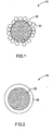
- the phosphor composition 10 comprises the second phosphor 30 disposed onto the first phosphor 20 as a layer of discrete particles as shown in Figure 1.
- the phosphor composition 15 includes the second phosphor 30 disposed onto the first phosphor 20 as a substantially continuous shell as depicted in Figure 2.
- the layer thickness ranges from about 10 nm to about 1000 nm.
- the layer thickness ranges from about 20 nm to about 600 nm and in yet another embodiment, the layer thickness ranges from about 40 nm to about 500 nm.
- the layer of particles may comprise a plurality of sub-layers; the total thickness of the plurality of sub-layers is generally within one of the thickness ranges set forth above.
- first and second phosphors present in the phosphor composition can be varied to suit the requirements of particular applications. The effect of adding increasing amounts of second phosphor will vary depending upon the particular first and second phosphors being used.
- the second phosphor is present in an amount ranging from about 1 weight percent to about 99 weight percent of the phosphor composition. In certain embodiments, the amount of second phosphor is in the range from about 20 weight percent to about 35 weight percent, and in particular embodiments this amount is in the range from about 15 weight percent to about 25 weight percent.
- the first phosphor includes a plurality of particles having at least one dimension in a range from about 10 nanometers to about 10 microns. In certain embodiments, the first phosphor includes a plurality of particles having at least one dimension in a range from about 500 nanometers to about 5 microns, and in particular embodiments at least one dimension is in a range from about 1 micron to about 3 microns. Second phosphor 30 preferably has dimensions in the nanometer range ( ⁇ 100 nm), so that it does not attenuate the light emission from the first phosphor.
- the second phosphor includes a plurality of particles having at least one dimension in a range from about 20 nanometers to about 80 nanometers, in other embodiments, the second phosphor comprises a plurality of particles having at least one dimension in a range from about 30 nanometers to about 40 nanometers.
- the first and the second phosphors may have any morphology. They may have same or different morphology. Suitable morphologies include, but are not limited to, spherical morphology, ellipsoidal morphology, elongated platelet morphology, rod-like morphology, needle-like morphology.
- the first phosphor substantially absorbs at least a portion of the electromagnetic radiation in a wavelength range from about 120 nm to about 500 nm of the electromagnetic spectrum and substantially emits at least a portion of the electromagnetic radiation in the wavelength region from about 220 nm to about 750 nm of the electromagnetic spectrum.
- the first phosphor comprises at least a phosphor selected from a group consisting of BaMg 2 Al 16 O 27 :Eu 2+ ; CeMgAl 11 O 19 :Tb 3+ ; Y 2 O 3 :Eu 3+ ;(Ba,Sr,Ca) 5 (PO 4 ) 3 (Cl,F,OH):Eu 2+ ; (Ba,Sr,Ca)MgAl 10 O 17 :Eu 2+ ; (Ba,Sr,Ca)BPO 5 :Eu 2+ ; Sr 4 Al 14 O 25 :Eu 2+ ; BaAl 8 O 13 :Eu 2+ ; 2SrO ⁇ 0.84P 2 O 5 ⁇ 0.16B 2 O 3 :Eu 2+ ; MgWO 4 ; BaTiP 2 O 8 ; LaPO 4 :Ce 3+ ,Tb 3+ ; GdMgB 5 O 10 :(Ce 3+ ,Tb 3+
- More than one type of first phosphors can be used in the phosphor composition, for example, to produce visible light having different colors.
- a blend of different first phosphors emitting in the blue, green, and red wavelength ranges may be used.
- a light source using a phosphor in accordance with the present invention may use a combination of BaMg 2 Al 16 O 27 :Eu 2+ as the blue light-emitting phosphor, CeMgAl 11 O 19 :Tb 3+ as the green light-emitting phosphor, and Y 2 O 3 :Eu 3+ as the red light-emitting phosphor to produce white light.
- blue light-emitting phosphors are (Ba,Sr,Ca) 5 (PO 4 ) 3 (Cl,F,OH):Eu 2+ ; (Ba,Sr,Ca)MgAl 10 O 17 :Eu 2+ ; and (Ba,Sr,Ca)BPO5:Eu 2+ .
- Non-limiting examples of phosphors that emit blue-green light are Sr 4 Al 14 O 25 :Eu 2+ ; BaAl 8 O 13 :Eu 2+ ; 2SrO ⁇ 0.84P 2 O 5 ⁇ 0.16B 2 O 3 :Eu 2+ .
- Other non-limiting examples of phosphors that emit green light are LaPO 4 :Ce 3+ ,Tb 3+ ; GdMgB 5 O 10 :Ce 3+ , Tb 3+ , Mn 2+ ; and GdMgB 5 O 10 :Ce 3+ , Tb 3+ .
- Non-limiting examples of phosphors that emit yellow-orange light are (Tb,Y,Lu,La,Gd) 3 (Al,Ga)5O 12 :Ce 3+ ; and (Ba,Sr,Ca) 5 (PO 4 ) 3 (Cl,F,OH):Eu 2+ , Mn 2+ , Sb 3+ .
- phosphors that emit red light are (Y,Gd,La,Lu, Sc) 2 O 3 :Eu 3+ ; (Y,Gd,La,In,Lu,Sc)BO 3 :Eu 3+ ; (Y,Gd,La)(Al,Ga)O 3 :Eu 3+ ; (Ba,Sr,Ca)(Y,Gd, La,Lu) 2 O 4 :Eu 3+ ; (Y,Gd)Al 3 B 4 O 12 : Eu 3+ ; monoclinic Gd 2 O 3 :Eu 3+ ; (Gd,Y) 4 (Al,Ga) 2 O 9 :Eu 3+ ; (Ca,Sr)(Gd,Y) 3 (Ge,Si)Al 3 O 9 :Eu 3+ ; (Sr,Mg) 3 (PO 4 ) 2 :Sn 2+ ; GdMgB 5 O 10 :Ce 3+ ,
- the second phosphor is a visible light emitting phosphor, that substantially absorbs at least a portion of the electromagnetic radiation in a wavelength range from about 120 nm to about 500 nm of the electromagnetic spectrum and emits at least a portion of the electromagnetic radiation in a wavelength range from about 220 nm to about 750 nm of the electromagnetic spectrum; in yet another embodiment, the second phosphor is a quantum splitting phosphor that substantially absorbs at least a portion of electromagnetic radiation in a wavelength range from about 120 nm to about 230 nm region of the electromagnetic spectrum and substantially emits at least a portion of the electromagnetic radiation in a wavelength range from about 220 nm to about 750 nm region of the electromagnetic spectrum; and yet in another embodiment the second phosphor is a UV emitting phosphor that substantially absorbs at least a portion of the electromagnetic radiation in the wavelength region from about 120 nm to about 230 nm of the electromagnetic spectrum and substantially emits at least a portion of the electromagnetic radiation in the wavelength region from about 220
- the second phosphor includes a visible light emitting phosphor selected from a group consisting of BaMg 2 Al 16 O 27 :Eu 2+ ; CeMgAl 11 O 19 :Tb 3+ ; Y 2 O 3 :Eu 3+ ;(Ba,Sr,Ca) 5 (PO 4 ) 3 (Cl,F,OH):Eu 2+ ; (Ba,Sr,Ca)MgAl 10 O 17 :Eu 2+ ; (Ba,Sr,Ca)BPO 5 :Eu 2+ ; Sr 4 Al 14 O 25 :Eu 2+ ; BaAl B O 13 :EU 2+ ; 2SrO ⁇ 0.84P 2 O 5 ⁇ 0.16B 2 O 3 :EU 2+ ; MgWO 4 ; BaTiP 2 O 8 ; LaPO 4 :Ce 3+ ,Tb 3+ ; GdMgB 5 O 10 :(Ce 3+ ,Tb 3+
- the second phosphor includes a quantum splitting phosphor.
- the second phosphor are LaPO 4 :Pr 3+ , LaB 3 O 6 :Pr 3+ , LaBO 3 :Pr 3+ , YBO 3 :Pr 3+ , GdBO 3 :Pr 3+ , LuBO 3 :Pr 3+ , (Gd,Y)B 3 O 6 :Pr 3+ , (Sr,Ca)Al 12 O 19 : Pr 3+ , (La,Gd,Y)MgB 5 O 10 :Pr 3+ , SrB 4 O 7 :Pr 3+ , CaMgAl 11.33 O 19 :Pr 3+ , CaMgAl 14 O 23 :Pr 3+ , YPO 4 :Pr 3+ , GdPO 4 :Pr 3+ , Y 2 SiO 5 :Pr 3+ , and YPO 4 :Bi 3
- Activator ions of Pb 2+ can also be used in the foregoing hosts, either alone or in combination with at least one of Pr3 + and Bi 3+ , to yield VUV radiation-absorbing phosphors (e.g.; LaPO 4 :Pr 3+ ,Pb 2+ ; LaB 3 O 6 :Pr 3+ ,Pb 2+ ; LaBO 3 :Pr 3+ ,Pb 2+ ; YBO 3 :Pr 3+ ,Pb 2+ ; GdBO 3 :Pr 3+ ,Pb 2+ ; LuBO 3 :Pr 3+ ,Pb 2+ ; (Gd,Y)B 3 O 6 :Pr 3+ ,Pb 2+ ; (Sr,Ca)Al 12 O 19 : Pr 3+ ,Pb 2+ ; (La,Gd,Y)MgB 5 O 10 :Pr 3+ ,Pb 2+ ; SrB 4 O 7 :Pr 3+ ,
- second phosphors are (Ca,Mg,Sr)SO 4 :Pb 2+ , CaLi 2 SiO 4 :Pb 2+ , (Ca,Ba,Sr)SiO 3 :Pb 2+ , Ba(Y,Gd,Lu)B 9 O 16 :Bi 3+ , YF 3 :Bi 3+ , YOF:Bi 3+ , (Gd,Y)OF:Bi 3+ ,Pr 3+ , and (Y,Gd) 3 Al 5 O 12 :Bi 3+ . More than one type of second phosphors can be used, for example, to ensure that substantially all of the VUV emitted by the plasma is absorbed.
- Figure 3 is a transmission electron microscopy image of LaPO 4 :Pr 3+ disposed onto Y 2 O 3 :Eu 3+ .
- the image shows a particle of Y 2 O 3 :Eu 3+ coated with a plurality of LaPO 4 :Pr 3+ nanoparticles.
- Figure 4 shows a high resolution electron micrograph of a nanoparticle of LaPO 4 :Pr 3+ disposed onto Y 2 O 3 :Eu 3+ (phosphor composition 40).
- FIG 5 is an emission spectrum of Y 2 O 3 :Eu 3+ under 254 nm excitation with and without LaPO 4 :Pr 3+ coating.
- the emission spectrum remains the same with and without the coating, implying that LaPO 4 :Pr 3+ coating does not hinder the light emission from Y 2 O 3 :Eu 3+ .
- Another aspect of the invention is to provide a method for preparing a phosphor composition.
- the method of making a phosphor composition is shown as a flow diagram in Figure 6.
- the method 50 begins with step 60, wherein a first phosphor including a visible light emitting phosphor is provided.
- a second phosphor is provided and the second phosphor is disposed onto the first phosphor in step 80.
- the second phosphor may be provided and disposed onto the first phosphor in situ or ex situ.
- the process is termed in situ when the second phosphor is produced during the coating process.
- a flow chart illustrating an in situ process (method 90) is depicted in figure 7.
- FIG. 8 illustrates the ex-situ process (method 100) of preparing the phosphor composition.
- the size and shape of the phosphors may vary including the size ranges and morphologies specified in the composition embodiments.
- Particles of phosphors used may be prepared by any synthesis method known in the art.
- phosphors are provided dispersed in a liquid medium. Any suitable liquid medium may be used. In some embodiments, the liquid medium includes water.
- the method may further optionally include providing the first phosphor and the second phosphor with protective coatings to prevent lumen degradation during coating.
- the protective coating may be provided for the first phosphor only, the second phosphor only, or for both the first and the second phosphor.
- the protective coating is obtained on the phosphor by mixing a dispersion of the phosphor with a surfactant.
- the dispersion comprising the phosphor and the surfactant is heated to a sufficient temperature to a sufficient duration of time to obtain a chemically stable protective coating, which can protect the phosphor from the reacting media during processing. Any of a number of commercially available surfactants is suitable for use in embodiments of the present invention.
- Surfactant comprises at least one surfactant selected from a group consisting of cationic surfactants, anionic surfactants, non-ionic phosphor and combinations thereof; wherein the non-ionic surfactants are selected from the group consisting of polar surfactants, non-polar surfactants, and combinations thereof.
- the amount of the first phosphor and second phosphor may vary depending on the final phosphor composition needed. In addition, the effect of adding increasing amounts of second phosphor will vary depending upon the particular first and second phosphors being used.
- the second phosphor is present in an amount ranging from about 1 weight percent to about 99 weight percent of the phosphor composition. In certain embodiments, the amount of second phosphor is in the range from about 20 weight percent to about 35 weight percent, and in particular embodiments this amount is in the range from about 15 weight percent to about 25 weight percent.
- the reactants necessary to obtain second phosphor are provided.
- a precursor of the second phosphor is disposed in a medium to form a solution, a gel, a suspension, a colloid, or a dispersion.
- precursors include nitrates, chlorides, alkoxides, acetates and oxides.
- the medium preferably has a low viscosity to facilitate flow and adequate mixing.
- a source of anion is added to the above solution in an optional step 115.
- a PO 4 3- source such as phosphoric acid or ammonium hydrogen phosphate may be provided.
- a surfactant solution is added optionally in step 117.
- disposing the second phosphor onto the first phosphor in situ includes mixing the mixture including the reactants necessary to obtain a precursor of the second phosphor, the surfactant, source of anions (added if required) with the dispersion of the first phosphor disposed in a medium (obtained in step 112), in step 120.
- an intermediate composition of the second phosphor is precipitated by raising the pH of the above mixture by adding a basic component, in step 130.
- Any suitable base may be used.
- suitable basic components are sodium hydroxide, tetra methyl ammonium hydroxide, and ammonium hydroxide.
- the intermediate composition of the second phosphor is converted into the desired second phosphor phase by heating to a reaction temperature, in step 140.
- the heating temperature may vary and depends on the composition of the phosphor. In general, certain oxide phosphor compositions may require higher temperatures to form the desired phase, while phosphate phosphor compositions may require lower temperatures.
- Nanoparticles of the second phosphor are prepared by a separate process, and used in the process of the present invention.
- Nanoparticles of inorganic materials such as the second phosphors herein disclosed, may be prepared by a number of methods.
- One method of preparation is flame spray pyrolysis of a solution of the precursors of the inorganic material. Such a method is described, for example, in U.S. Patent 5,958,361 , which is incorporated herein in its entirety by reference.
- an organometallic compound that comprises the desired metals and other heteroatoms in appropriate ratios (to achieve the final chemical composition of the phosphor) is dissolved in a combustible solvent, in which the organomettalic compound is soluble, to form a solution.
- the solution is then aerosolized into a flame spray pyrolysis reactor in the presence of excess oxygen.
- the volatile solvent is burned, and the precursors decomposed to produce an inorganic vapor in the correct chemical composition of the final phosphor.
- the inorganic vapor condenses rapidly in a steep temperature gradient to form nanometer-sized particles of the phosphor.
- a variation of this technique is found in R.
- thermodynamically stable and optically isotropic dispersion of aqueous microdroplets in a continuous organic (oil) phase is first prepared.
- the aqueous microdroplets contain inorganic compounds or their precursors in appropriate proportions to achieve the desired final phosphor composition.
- microdroplets are stabilized by surfactant molecules at the water-oil interface.
- the microemulsion is pyrolyzed to produce nanometer-sized particle of the final inorganic material. This technique can produce particle size in the range of about 5-30 nm.
- Nanocrystalline inorganic materials are produced by precipitation by a hydroxide, such as ammonium hydroxide, from a soluble precursor mixture containing all of the desired elements.
- particle sizes in the range from about 20 to 40 nm are produced by this method.
- a dispersion of second phosphor is formed in a liquid medium, in step 150, and another dispersion of the first phosphor is formed in a liquid medium in step 155.
- the liquid medium comprises water.
- disposing the second phosphor onto the first phosphor includes mixing the dispersion of the first phosphor obtained in step 150, and the dispersion of the second phosphor obtained in step 160 with a surfactant in step 160. The mixture is stirred in step 170.
- a plurality of nanoparticles of the second phosphor having an average primary crystallite size of less than about 100 nm are precipitated onto the first phosphor, in step 180. If needed, any excess organic material is removed by heating, in step 190.
- Figure 9 illustrates the flow chart of an ex situ process (method 110), where the first phosphor and the second phosphor are provided with a protective organic coating.
- a dispersion the second phosphor is formed in a liquid medium, in step 152.
- the liquid medium comprises water.
- a surfactant solution is added to the above dispersion in step 154. Any suitable surfactant selected from a group consisting of ionic surfactants, non-ionic surfactants and amphiphilic polymers may be used.
- the resulting mixture is heated to form a protected second phosphor system in step 157.
- the temperature is preferably sufficient to remove most of the organic material, but leaves a protective coating covering the second phosphor, and will be dependent on the type of surfactant used, but typically above 200°C.
- the protected second phosphor system is redispersed in a liquid medium in step 159.
- the liquid medium comprises water.
- a similar process can optionally occur for the first phosphor and is described in steps 165, 167, and 169.
- the protection can optionally occur for the first phosphor only, the second phosphor only, or for both first and second phosphor prior to step 175.
- disposing the second phosphor onto the first phosphor includes mixing the mixture including a dispersion of the protected second phosphor with a dispersion of the protected first phosphor (obtained at step 167) with a surfactant in step 175.
- a plurality of nanoparticles of the protected second phosphor having an average primary crystallite size of less than about 100 nm are precipitated onto the protected first phosphor, in step 185. Any excess organic material is removed by heating, in step 195.
- Heating temperature may vary depending on the organic residue present. Typically heating temperature ranges from about 100°C to about 1000°C. In one embodiment, it is from 200°C to about 800°C and in another embodiment the heating temperature ranges from about 400°C to about 600°C.
- the following example describes the preparation method for an ex-situ process with two side protection for preparing a hybrid phosphor containing LaPO 4 :Pr 3+ (LAP:Pr) nano size particles disposed onto Y 2 O 3 :Eu 3+ (YEO) micron size phosphor particles.
- Desired amount of LAP:Pr nano particles was dispersed in a surfactant solution and stirred for 30 minutes. Desired amount of YEO was dispersed separately in a surfactant solution and stirred for 30 minutes. Each solution was poured into a glazed porcelain dish, and dried for 10 hr in a drying oven at 100°C. The dish was transferred to a furnace and heated up to 600°C and cooled to room temperature. The white powder obtained was ground in a mortar and pestle and sieved through 100 mesh nylon. The two dispersions containing protected particles were re-dispersed and mixed with a surfactant solution and stirred for 30 min. The pH was raised and the mixture was heated to temperatures above 600°C. The hybrid phosphor was collected, ground, and sieved.
Landscapes
- Chemical & Material Sciences (AREA)
- Engineering & Computer Science (AREA)
- Materials Engineering (AREA)
- Organic Chemistry (AREA)
- Inorganic Chemistry (AREA)
- Luminescent Compositions (AREA)
Abstract
Description
- The invention relates generally to a method of making a hybrid phosphor composition.
- Light generation in mercury low-pressure gas discharge lamps is based on the principle that during the gas discharge, a plasma develops in the mercury-containing gas filling within the lamp and emits electromagnetic ("EM") radiation predominantly in the ultraviolet ("UV") wavelength range. The UV radiation emitted by a low-pressure mercury discharge concentrates at wavelengths of about 254 nm and about 185 nm. A phosphor, which is typically coated on the lamp housing, is employed to convert the UV radiation into visible light.
- One drawback of known mercury low-pressure gas discharge lamps is that the emissivity of the phosphors tend to decrease over the course of time due to degradation caused by the action of at least some of the incident UV radiation on the phosphor coating, the recombination of mercury ions and electrons on the phosphor surface, and the incidence of excited mercury atoms and electrons on the phosphor layer. This emissivity loss results in the reduction of the electro-optical efficiency in the course of the service life of the lamp. This degradation is particularly substantial under the influence of VUV (vacuum ultra violet) radiation, and especially that portion of VUV radiation having a wavelength below 200 nm. Degradation of the phosphor in a light source typically manifests itself as a shift of the color of the emitted light. Moreover, most of the phosphors used in current fluorescent lamps are only sensitive to radiation with wavelength around 254 nm, and consequently the mercury discharge radiation at about 185 nm wavelength does not contribute to the overall light out put of the lamp.
- Therefore, effort has been devoted to finding means to improve the lumen efficiency of mercury discharge lamps. One approach is to use a mixture of phosphor particles and nano particles of aluminum oxide having a particle size of about 20 nm for a coating on the inner surface of the lamp housing. The aluminum oxide particles absorb the VUV radiation, but are transparent with respect to UV radiation having wavelength of 254 nm. As can be appreciated, this method would still allow some VUV radiation to be incident on the phosphor particles. However, aluminum oxide does not emit any light, thus, does not help to increase the efficiency of the lamp. Yet another approach is to utilize a two-layer micron size phosphor coating. The first layer exposed to the mercury discharge is a capable of absorbing VUV radiation and emitting in the wavelength range of 230 to 280 nm. The second layer is disposed between the first layer and the inner surface of the lamp housing and includes phosphors that absorb the shorter-wavelength UV radiation and emit visible light. However, this method may result in performance degradation due to significant scattering of the 254nm radiation.
- Therefore, it is desirable to continue to search for other means to improve the light output and decrease lumen depreciation. It is also very desirable to achieve this goal and to improve the electro-optical efficiency of these devices at the same time.
- The present invention meets these and other needs by a method for making a phosphor composition.
- Accordingly, one aspect of the invention is to provide a phosphor composition. The phosphor composition includes a first phosphor includes a visible-light-emitting phosphor; and a second phosphor having an average primary crystallite size of less than about 100 nm. The second phosphor includes at least one phosphor selected from a group consisting of a visible light emitting phosphor, ultraviolet (VUV) light emitting phosphor, and a quantum splitting phosphor.
- A second aspect of the invention is to provide a method of making a phosphor composition. The method includes the steps of providing a first phosphor including a visible-light-emitting phosphor; providing a second phosphor having an average primary crystallite size of less than about 100 nm and disposing the second phosphor onto the first phosphor. The second phosphor includes at least one phosphor selected from a group consisting of a visible light emitting phosphor, ultraviolet (VUV) light emitting phosphor, and a quantum splitting phosphor.
- The invention will now be described in greater detail, by way of example, with reference to the drawings, in which:-
- FIG 1 is a schematic representation of a phosphor composition, according to one embodiment of the present invention;
- FIG 2 is a schematic representation of a phosphor composition, according to another embodiment of the present invention;
- FIG 3 is a transmission electron microscopy (TEM) image of LaPO4:Pr3+ disposed onto Y2O3:Eu3+;
- FIG 4 is a high resolution transmission electron microscopy (HRTEM) image of a LaPO4:Pr3+ disposed onto Y2O3:Eu3+;
- FIG 5 is a emission spectrum of Y2O3:Eu3+ with and without LaPO4:Pr3+ coating; and
- FIG 6, 7 and 8 and 9 are flow charts illustrating methods for making a phosphor composition, according to certain embodiments of the invention.
- In the following description, like reference characters designate like or corresponding parts throughout the several views shown in the figures. It is also understood that terms such as "top," "bottom," "outward," "inward," and the like are words of convenience and are not to be construed as limiting terms. Furthermore, whenever a particular aspect of the invention is said to comprise or consist of at least one of a number of elements of a group and combinations thereof, it is understood that the aspect may comprise or consist of any of the elements of the group, either individually or in combination with any of the other elements of that group.
- Referring to the drawings in general, it will be understood that the illustrations are for the purpose of describing one embodiment of the invention and are not intended to limit the invention thereto.
- As used herein, 'hybrid phosphor composition' or simply termed a 'phosphor composition' refers to a composite of phosphors, wherein a second phosphor may be the same composition as the first phosphor or a different composition from the first phosphor. In some embodiments, the second phosphor is disposed onto the first phosphor. The conversion of a single ultraviolet (UV) photon into more than one visible (vis) photons with the result that the quantum efficiency of luminescence exceeds unity is termed quantum splitting.
- Schematic representations of a phosphor composition according to two different embodiments of the present invention are shown in Figure 1 and Figure 2. The phosphor composition includes a first phosphor (20) including a visible-light-emitting phosphor; and a second phosphor (30) having an average primary crystallite size of less than about 100 nm. The second phosphor includes at least one phosphor selected from a group consisting of a visible light emitting phosphor, an ultraviolet light emitting phosphor, and a quantum splitting phosphor. In one embodiment, the
phosphor composition 10 comprises thesecond phosphor 30 disposed onto thefirst phosphor 20 as a layer of discrete particles as shown in Figure 1. In another embodiment, thephosphor composition 15 includes thesecond phosphor 30 disposed onto thefirst phosphor 20 as a substantially continuous shell as depicted in Figure 2. When thesecond phosphor 30 is disposed onto thefirst phosphor 20 as a layer of discrete particles, in one embodiment, the layer thickness ranges from about 10 nm to about 1000 nm. In another embodiment, the layer thickness ranges from about 20 nm to about 600 nm and in yet another embodiment, the layer thickness ranges from about 40 nm to about 500 nm. The layer of particles may comprise a plurality of sub-layers; the total thickness of the plurality of sub-layers is generally within one of the thickness ranges set forth above. - When the
second phosphor 30 is disposed onto thefirst phosphor 20 as a substantially continuous shell, some discontinuity may exist as long as such discontinuity does not lead to substantial degradation of the luminescent property of the hybrid phosphor composition with use. The amounts of first and second phosphors present in the phosphor composition can be varied to suit the requirements of particular applications. The effect of adding increasing amounts of second phosphor will vary depending upon the particular first and second phosphors being used. In one embodiment, the second phosphor is present in an amount ranging from about 1 weight percent to about 99 weight percent of the phosphor composition. In certain embodiments, the amount of second phosphor is in the range from about 20 weight percent to about 35 weight percent, and in particular embodiments this amount is in the range from about 15 weight percent to about 25 weight percent. - In some embodiments, the first phosphor includes a plurality of particles having at least one dimension in a range from about 10 nanometers to about 10 microns. In certain embodiments, the first phosphor includes a plurality of particles having at least one dimension in a range from about 500 nanometers to about 5 microns, and in particular embodiments at least one dimension is in a range from about 1 micron to about 3 microns.
Second phosphor 30 preferably has dimensions in the nanometer range (<100 nm), so that it does not attenuate the light emission from the first phosphor. In some embodiments, the second phosphor includes a plurality of particles having at least one dimension in a range from about 20 nanometers to about 80 nanometers, in other embodiments, the second phosphor comprises a plurality of particles having at least one dimension in a range from about 30 nanometers to about 40 nanometers. The first and the second phosphors may have any morphology. They may have same or different morphology. Suitable morphologies include, but are not limited to, spherical morphology, ellipsoidal morphology, elongated platelet morphology, rod-like morphology, needle-like morphology. - In some embodiments, the first phosphor substantially absorbs at least a portion of the electromagnetic radiation in a wavelength range from about 120 nm to about 500 nm of the electromagnetic spectrum and substantially emits at least a portion of the electromagnetic radiation in the wavelength region from about 220 nm to about 750 nm of the electromagnetic spectrum.
- In certain embodiments, the first phosphor comprises at least a phosphor selected from a group consisting of BaMg2Al16O27:Eu2+; CeMgAl11O19:Tb3+; Y2O3:Eu3+;(Ba,Sr,Ca)5(PO4)3(Cl,F,OH):Eu2+; (Ba,Sr,Ca)MgAl10O17:Eu2+; (Ba,Sr,Ca)BPO5:Eu2+; Sr4Al14O25:Eu2+; BaAl8O13:Eu2+; 2SrO·0.84P2O5·0.16B2O3:Eu2+; MgWO4; BaTiP2O8; LaPO4:Ce3+,Tb3+; GdMgB5O10:(Ce3+,Tb3+,Mn2+); GdMgB5O10:(Ce3+,Tb3+); (Tb,Y,Lu,La,Gd)3(Al,Ga)5O12:Ce3+; (Ba,Sr,Ca)5(PO4)3(Cl,F,OH):(Eu2+, Mn2+,Sb3+); (Y,Gd,La,Lu,Sc)2O3:Eu3+; (Y,Gd,La,In,Lu,Sc)BO3:Eu3+; (Y,Gd,La)(Al,Ga)O3:Eu3+; (Ba,Sr,Ca)(Y,Gd,La,Lu)2O4:Eu3+; (Y,Gd)Al3B4O12:Eu3+: monoclinic Gd2O3:Eu3+; (Gd,Y)4(Al,Ga)2O9:Eu3+; (Ca,Sr)(Gd,Y)3(Ge,Si)Al3O9:Eu3+; GdMgB5O10:(Ce3+,Mn2+); 3.5MgO·0.5MgF2·GeO2:Mn4+, and combinations thereof.
- More than one type of first phosphors can be used in the phosphor composition, for example, to produce visible light having different colors. For example, when white light is desired from a light source using the phosphor of the present invention, a blend of different first phosphors emitting in the blue, green, and red wavelength ranges may be used. As an example, a light source using a phosphor in accordance with the present invention may use a combination of BaMg2Al16O27:Eu2+ as the blue light-emitting phosphor, CeMgAl11O19:Tb3+ as the green light-emitting phosphor, and Y2O3:Eu3+ as the red light-emitting phosphor to produce white light.
- Other non-limiting examples of blue light-emitting phosphors are (Ba,Sr,Ca)5(PO4)3(Cl,F,OH):Eu2+; (Ba,Sr,Ca)MgAl10O17:Eu2+; and (Ba,Sr,Ca)BPO5:Eu2+. Non-limiting examples of phosphors that emit blue-green light are Sr4Al14O25:Eu2+; BaAl8O13:Eu2+; 2SrO·0.84P2O5·0.16B2O3:Eu2+. MgWO4; BaTiP2O8; (Ba,Sr,Ca)MgAl10O17:Eu2+,Mn2+; and (Ba,Sr,Ca)5(PO4)3(Cl,F,OH):Sb3+. Other non-limiting examples of phosphors that emit green light are LaPO4:Ce3+,Tb3+; GdMgB5O10:Ce3+, Tb3+, Mn2+; and GdMgB5O10:Ce3+, Tb3+. Non-limiting examples of phosphors that emit yellow-orange light are (Tb,Y,Lu,La,Gd)3 (Al,Ga)5O12:Ce3+; and (Ba,Sr,Ca)5(PO4)3(Cl,F,OH):Eu2+, Mn2+, Sb3+. Other non-limiting examples of phosphors that emit red light are (Y,Gd,La,Lu, Sc)2O3:Eu3+; (Y,Gd,La,In,Lu,Sc)BO3:Eu3+; (Y,Gd,La)(Al,Ga)O3:Eu3+; (Ba,Sr,Ca)(Y,Gd, La,Lu)2O4:Eu3+; (Y,Gd)Al3B4O12: Eu3+; monoclinic Gd2O3:Eu3+; (Gd,Y)4(Al,Ga)2O9:Eu3+; (Ca,Sr)(Gd,Y)3(Ge,Si)Al3O9:Eu3+; (Sr,Mg)3(PO4)2:Sn2+; GdMgB5O10:Ce3+, Mn2+; and 3.5MgO·0.5MgF2·GeO2:Mn4+. Any of the compositions set forth above is suitable for use as a first phosphor in accordance with embodiments of the present invention.
- In one embodiment, the second phosphor is a visible light emitting phosphor, that substantially absorbs at least a portion of the electromagnetic radiation in a wavelength range from about 120 nm to about 500 nm of the electromagnetic spectrum and emits at least a portion of the electromagnetic radiation in a wavelength range from about 220 nm to about 750 nm of the electromagnetic spectrum; in yet another embodiment, the second phosphor is a quantum splitting phosphor that substantially absorbs at least a portion of electromagnetic radiation in a wavelength range from about 120 nm to about 230 nm region of the electromagnetic spectrum and substantially emits at least a portion of the electromagnetic radiation in a wavelength range from about 220 nm to about 750 nm region of the electromagnetic spectrum; and yet in another embodiment the second phosphor is a UV emitting phosphor that substantially absorbs at least a portion of the electromagnetic radiation in the wavelength region from about 120 nm to about 230 nm of the electromagnetic spectrum and substantially emits at least a portion of the electromagnetic radiation in the wavelength region from about 220 nm to about 340 nm of the electromagnetic spectrum; or a combination of such phosphors.
- In some embodiments, the second phosphor includes a visible light emitting phosphor selected from a group consisting of BaMg2Al16O27:Eu2+; CeMgAl11O19:Tb3+; Y2O3:Eu3+;(Ba,Sr,Ca)5(PO4)3(Cl,F,OH):Eu2+; (Ba,Sr,Ca)MgAl10O17:Eu2+; (Ba,Sr,Ca)BPO5:Eu2+; Sr4Al14O25:Eu2+; BaAlBO13:EU2+; 2SrO·0.84P2O5·0.16B2O3:EU2+; MgWO4; BaTiP2O8; LaPO4:Ce3+,Tb3+; GdMgB5O10:(Ce3+,Tb3+,Mn2+); GdMgB5O10:(Ce3+,Tb3+); (Tb,Y,Lu,La,Gd)3(Al,Ga)5O12:Ce3+; (Ba,Sr,Ca)5(PO4)3(Cl,F,OH):(Eu2+, Mn2+,Sb3+); (Y,Gd,La,Lu,Sc)2O3:Eu3+; (Y,Gd,La,ln,Lu,Sc)B03:Eu3+; (Y,Gd,La)(Al,Ga)O3:Eu3+; (Ba,Sr,Ca)(Y,Gd,La,Lu)2O4:Eu3+; (Y,Gd)Al3B4O12:Eu3+; monoclinic Gd2O3:Eu3+; (Gd,Y)4(Al,Ga)2O9:Eu3+; (Ca,Sr)(Gd,Y)3(Ge,Si)Al3O9:Eu3+; GdMgB5O10:(Ce3+,Mn2+); 3.5MgO·0.5MgF2·GeO2:Mn4+, and combinations thereof.
- In some other embodiments, the second phosphor includes a quantum splitting phosphor. Non-limiting examples of the second phosphor are LaPO4:Pr3+, LaB3O6:Pr3+, LaBO3:Pr3+, YBO3:Pr3+, GdBO3:Pr3+, LuBO3:Pr3+, (Gd,Y)B3O6:Pr3+, (Sr,Ca)Al12O19: Pr3+, (La,Gd,Y)MgB5O10:Pr3+, SrB4O7:Pr3+, CaMgAl11.33O19:Pr3+, CaMgAl14O23:Pr3+, YPO4:Pr3+, GdPO4:Pr3+, Y2SiO5:Pr3+, and YPO4:Bi3+, LuPO4:Bi3+. Activator ions of Pb2+ can also be used in the foregoing hosts, either alone or in combination with at least one of Pr3+ and Bi3+, to yield VUV radiation-absorbing phosphors (e.g.; LaPO4:Pr3+,Pb2+; LaB3O6:Pr3+,Pb2+; LaBO3:Pr3+,Pb2+; YBO3:Pr3+,Pb2+; GdBO3:Pr3+,Pb2+; LuBO3:Pr3+,Pb2+; (Gd,Y)B3O6:Pr3+,Pb2+; (Sr,Ca)Al12O19: Pr3+,Pb2+; (La,Gd,Y)MgB5O10:Pr3+,Pb2+; SrB4O7:Pr3+,Pb2+; CaMgAl11.33O19:Pr3+,Pb2+; CaMgAl14O23:Pr3+,Pb2+; YPO4:Pr3+,Pb2+; GdPO4:Pr3+,Pb2+; Y2SiO5:Pr3+,Pb2+; YP04:Bi3+,Pb2+; LuPO4:Bi3+,Pb2+; LaPO4:Pr3+,Pb2+,Bi3+; LaB3O6:Pr3+,Pb2+,Bi3+; LaB03:Pr3+,Pb2+,Bi3+; YBO3:Pr3+,Pb2+,Bi3+; GdBO3:Pr3+,Pb2+,Bi3+; LuBO3:Pr3+,Pb2+,Bi3+; (Gd,Y)B3O6:Pr3+,Pb2+,Bi3+; (Sr,Ca)Al12O19:Pr+ ,Pb2+ ,Bi3+; (La,Gd,Y)MgB5O10:Pr3+,Pb2+,Bi3+; SrB4O7:Pr3+,Pb2+,Bi3+; CaMgAl11.33O19:Pr3+,Pb2+,Bi3+; CaMgAl14O23:Pr3+,Pb2+,Bi3+; YPO4:Pr3+,Pb2+,Bi3+; GdPO4:Pr3+,Pb2+,Bi3+; Y2SiO5:Pr3+,Pb2+,Bi3+; YPO4:Pr3+,Bi3+,Pb2+; or LuPO4:Pr3+,Bi3+,Pb2+). Other suitable second phosphors are (Ca,Mg,Sr)SO4:Pb2+, CaLi2SiO4:Pb2+, (Ca,Ba,Sr)SiO3:Pb2+, Ba(Y,Gd,Lu)B9O16:Bi3+, YF3:Bi3+, YOF:Bi3+, (Gd,Y)OF:Bi3+,Pr3+, and (Y,Gd)3Al5O12:Bi3+. More than one type of second phosphors can be used, for example, to ensure that substantially all of the VUV emitted by the plasma is absorbed.
- Figure 3 is a transmission electron microscopy image of LaPO4:Pr3+ disposed onto Y2O3:Eu3+. The image shows a particle of Y2O3:Eu3+ coated with a plurality of LaPO4:Pr3+ nanoparticles. Figure 4 shows a high resolution electron micrograph of a nanoparticle of LaPO4:Pr3+ disposed onto Y2O3:Eu3+ (phosphor composition 40).
- FIG 5 is an emission spectrum of Y2O3:Eu3+ under 254 nm excitation with and without LaPO4:Pr3+ coating. The emission spectrum remains the same with and without the coating, implying that LaPO4:Pr3+ coating does not hinder the light emission from Y2O3:Eu3+.
- Another aspect of the invention is to provide a method for preparing a phosphor composition. The method of making a phosphor composition is shown as a flow diagram in Figure 6. The
method 50 begins withstep 60, wherein a first phosphor including a visible light emitting phosphor is provided. Instep 70, a second phosphor is provided and the second phosphor is disposed onto the first phosphor instep 80. The second phosphor may be provided and disposed onto the first phosphor in situ or ex situ. The process is termed in situ when the second phosphor is produced during the coating process. A flow chart illustrating an in situ process (method 90) is depicted in figure 7. The process is termed ex-situ when the second phosphor is made in a separate process and then disposed onto the first phosphor during the process of the present invention. Figure 8 illustrates the ex-situ process (method 100) of preparing the phosphor composition. - The size and shape of the phosphors may vary including the size ranges and morphologies specified in the composition embodiments. Particles of phosphors used may be prepared by any synthesis method known in the art. Generally, phosphors are provided dispersed in a liquid medium. Any suitable liquid medium may be used. In some embodiments, the liquid medium includes water.
- The method may further optionally include providing the first phosphor and the second phosphor with protective coatings to prevent lumen degradation during coating. The protective coating may be provided for the first phosphor only, the second phosphor only, or for both the first and the second phosphor. In some embodiments, the protective coating is obtained on the phosphor by mixing a dispersion of the phosphor with a surfactant. In some embodiments, the dispersion comprising the phosphor and the surfactant is heated to a sufficient temperature to a sufficient duration of time to obtain a chemically stable protective coating, which can protect the phosphor from the reacting media during processing. Any of a number of commercially available surfactants is suitable for use in embodiments of the present invention. Surfactant comprises at least one surfactant selected from a group consisting of cationic surfactants, anionic surfactants, non-ionic phosphor and combinations thereof; wherein the non-ionic surfactants are selected from the group consisting of polar surfactants, non-polar surfactants, and combinations thereof.
- The amount of the first phosphor and second phosphor may vary depending on the final phosphor composition needed. In addition, the effect of adding increasing amounts of second phosphor will vary depending upon the particular first and second phosphors being used. In one embodiment, the second phosphor is present in an amount ranging from about 1 weight percent to about 99 weight percent of the phosphor composition. In certain embodiments, the amount of second phosphor is in the range from about 20 weight percent to about 35 weight percent, and in particular embodiments this amount is in the range from about 15 weight percent to about 25 weight percent.
- When the second phosphor is provided in situ, generally in
step 110, the reactants necessary to obtain second phosphor are provided. Generally, a precursor of the second phosphor is disposed in a medium to form a solution, a gel, a suspension, a colloid, or a dispersion. Non-limiting examples of precursors include nitrates, chlorides, alkoxides, acetates and oxides. The medium preferably has a low viscosity to facilitate flow and adequate mixing. If required, a source of anion is added to the above solution in anoptional step 115. For example, in the synthesis of LaPO4:Pr, a PO4 3- source such as phosphoric acid or ammonium hydrogen phosphate may be provided. A surfactant solution is added optionally instep 117. In some exemplary embodiments, disposing the second phosphor onto the first phosphor in situ includes mixing the mixture including the reactants necessary to obtain a precursor of the second phosphor, the surfactant, source of anions (added if required) with the dispersion of the first phosphor disposed in a medium (obtained in step 112), instep 120. When the process is in-situ, an intermediate composition of the second phosphor is precipitated by raising the pH of the above mixture by adding a basic component, instep 130. Any suitable base may be used. Non-limiting examples of suitable basic components are sodium hydroxide, tetra methyl ammonium hydroxide, and ammonium hydroxide. The intermediate composition of the second phosphor is converted into the desired second phosphor phase by heating to a reaction temperature, instep 140. The heating temperature may vary and depends on the composition of the phosphor. In general, certain oxide phosphor compositions may require higher temperatures to form the desired phase, while phosphate phosphor compositions may require lower temperatures. - When the method is ex-situ, nanoparticles of the second phosphor are prepared by a separate process, and used in the process of the present invention. Nanoparticles of inorganic materials, such as the second phosphors herein disclosed, may be prepared by a number of methods. One method of preparation is flame spray pyrolysis of a solution of the precursors of the inorganic material. Such a method is described, for example, in
U.S. Patent 5,958,361 , which is incorporated herein in its entirety by reference. In this method, an organometallic compound that comprises the desired metals and other heteroatoms in appropriate ratios (to achieve the final chemical composition of the phosphor) is dissolved in a combustible solvent, in which the organomettalic compound is soluble, to form a solution. The solution is then aerosolized into a flame spray pyrolysis reactor in the presence of excess oxygen. The volatile solvent is burned, and the precursors decomposed to produce an inorganic vapor in the correct chemical composition of the final phosphor. The inorganic vapor condenses rapidly in a steep temperature gradient to form nanometer-sized particles of the phosphor. A variation of this technique is found in R. Baranwal et al., "Flame Spray Pyrolysis of Precursors as a Route to Nano-mullite Powder: Powder Characterization and Sintering Behavior," J. Am. Ceram. Soc., Vol. 84, No.5, pp. 951-61 (2001). - Another method for the preparation of the nanometer-sized particles of inorganic materials is based on the solution-phase inverse-microemulsion technique. A representative description of this technique is found in W. Que et al., "Preparation and Characterization of Erbium Oxalate and Erbium Oxide Nanoparticles by Microemulsion Technique," Materials Science and Engineering C, Vol. 16, pp. 51-54 (2001). In this technique, a thermodynamically stable and optically isotropic dispersion of aqueous microdroplets in a continuous organic (oil) phase is first prepared. The aqueous microdroplets contain inorganic compounds or their precursors in appropriate proportions to achieve the desired final phosphor composition. The microdroplets are stabilized by surfactant molecules at the water-oil interface. The microemulsion is pyrolyzed to produce nanometer-sized particle of the final inorganic material. This technique can produce particle size in the range of about 5-30 nm.
- Another method for the preparation of the nanometer-sized particles of inorganic materials is based on the sol-gel method. A representative description of this method is disclosed in R. Subramanian et al., "Synthesis of Nanocrystalline Yttria by Sol-Gel Method," Materials Letters, Vol. 48, pp. 342-346 (May 2001). Nanocrystalline inorganic materials are produced by precipitation by a hydroxide, such as ammonium hydroxide, from a soluble precursor mixture containing all of the desired elements. In an exemplary embodiment, particle sizes in the range from about 20 to 40 nm are produced by this method.
- Another method for the preparation of the nanometer-sized particles of inorganic materials is based on the colloidal method. Representative descriptions of this method and one of its variations are disclosed in R. Ramesh et al., "Optical Properties of Ce3+ in Self-Assembled Strontium Chloro(hydroxy)apatite Nanocrystals," J. Phys. Chem. B, Vol. 104, pp. 8351-8360 (2000); T.S. Ahmadi et al., "Low-Temperature Synthesis of Pure and Mn-Doped Willemite Phosphor (Zn2SiO4:Mn) in Aqueous Medium," Materials Research Bulletin, Vol. 35, pp. 1869-1879 (2000); and C. Feldmann et al., "Preparation of Sub-Micrometer LnPO4 Particles (Ln = La, Ce)," J. of Materials Science, Vol. 37, pp. 3251-3254 (2002). A mixture comprising reactants is stirred at high speed at an elevated temperature, and the cooled rapidly to produce nanometer-sized colloidal particles. It is expected that the resulting particle size varies inversely with respect to stirring speed and cooling rate. Particles sizes from about 10 nm to several thousand nanometers may be obtained.
- In an ex situ process (figure 8), in accordance with one embodiment of the present invention, a dispersion of second phosphor is formed in a liquid medium, in
step 150, and another dispersion of the first phosphor is formed in a liquid medium instep 155. In some embodiments, the liquid medium comprises water. In an exemplary embodiment of the present invention, disposing the second phosphor onto the first phosphor includes mixing the dispersion of the first phosphor obtained instep 150, and the dispersion of the second phosphor obtained instep 160 with a surfactant instep 160. The mixture is stirred instep 170. In an ex situ process, a plurality of nanoparticles of the second phosphor having an average primary crystallite size of less than about 100 nm are precipitated onto the first phosphor, instep 180. If needed, any excess organic material is removed by heating, instep 190. - Figure 9 illustrates the flow chart of an ex situ process (method 110), where the first phosphor and the second phosphor are provided with a protective organic coating. In one embodiment of the ex-situ process, a dispersion the second phosphor is formed in a liquid medium, in
step 152. In some embodiments, the liquid medium comprises water. A surfactant solution is added to the above dispersion instep 154. Any suitable surfactant selected from a group consisting of ionic surfactants, non-ionic surfactants and amphiphilic polymers may be used. The resulting mixture is heated to form a protected second phosphor system instep 157. The temperature is preferably sufficient to remove most of the organic material, but leaves a protective coating covering the second phosphor, and will be dependent on the type of surfactant used, but typically above 200°C. The protected second phosphor system is redispersed in a liquid medium instep 159. In some embodiments, the liquid medium comprises water. A similar process can optionally occur for the first phosphor and is described insteps - In an exemplary embodiment of the present invention, disposing the second phosphor onto the first phosphor includes mixing the mixture including a dispersion of the protected second phosphor with a dispersion of the protected first phosphor (obtained at step 167) with a surfactant in
step 175. In an ex situ process, a plurality of nanoparticles of the protected second phosphor having an average primary crystallite size of less than about 100 nm are precipitated onto the protected first phosphor, instep 185. Any excess organic material is removed by heating, instep 195. Heating temperature may vary depending on the organic residue present. Typically heating temperature ranges from about 100°C to about 1000°C. In one embodiment, it is from 200°C to about 800°C and in another embodiment the heating temperature ranges from about 400°C to about 600°C. - The following example serves to illustrate the features and advantages offered by the present invention, and not intended to limit the invention thereto.
- The following example describes the preparation method for an ex-situ process with two side protection for preparing a hybrid phosphor containing LaPO4:Pr3+ (LAP:Pr) nano size particles disposed onto Y2O3:Eu3+ (YEO) micron size phosphor particles.
- Desired amount of LAP:Pr nano particles was dispersed in a surfactant solution and stirred for 30 minutes. Desired amount of YEO was dispersed separately in a surfactant solution and stirred for 30 minutes. Each solution was poured into a glazed porcelain dish, and dried for 10 hr in a drying oven at 100°C. The dish was transferred to a furnace and heated up to 600°C and cooled to room temperature. The white powder obtained was ground in a mortar and pestle and sieved through 100 mesh nylon. The two dispersions containing protected particles were re-dispersed and mixed with a surfactant solution and stirred for 30 min. The pH was raised and the mixture was heated to temperatures above 600°C. The hybrid phosphor was collected, ground, and sieved.
Claims (6)
- A method of making a phosphor composition(60) comprising.i) providing a first phosphor (70) comprising a visible-light-emitting phosphor;ii) providing a second phosphor (80) having an average primary crystallite size of less than about 100 nm, and wherein the second phosphor (30) comprises at least one phosphor selected from a group consisting of a visual light emitting phosphor, ultraviolet (VUV) light emitting phosphor, and a quantum splitting phosphor; andiii) disposing said second phosphor on to said first phosphor (80).
- The method of Claim 1, wherein providing said first phosphor (70) further comprises providing said first phosphor with a protective coating.
- The method of Claim 1, wherein providing said second phosphor (80) further comprises providing said second phosphor with a protective coating.
- The method of Claim 1, wherein providing said second phosphor comprises providing a precursor of said second phosphor disposed in a medium to form at least one of a solution, a gel, a suspension, a colloid, and a dispersion.
- The method of Claim 1, wherein disposing said second phosphor onto said first phosphor (80) comprises raising pH of medium with a basic component to precipitate an intermediate composition of second phosphor.
- The method of Claim 1, wherein disposing said second phosphor onto said first phosphor (80) comprises precipitating a plurality of nanoparticles of said second phosphor having an average primary crystallite size of less than about 100 nm onto said first phosphor.
Applications Claiming Priority (1)
| Application Number | Priority Date | Filing Date | Title |
|---|---|---|---|
| US11/096,502 US20060222757A1 (en) | 2005-03-31 | 2005-03-31 | Method for making phosphors |
Publications (1)
| Publication Number | Publication Date |
|---|---|
| EP1710289A1 true EP1710289A1 (en) | 2006-10-11 |
Family
ID=36218306
Family Applications (1)
| Application Number | Title | Priority Date | Filing Date |
|---|---|---|---|
| EP06250415A Withdrawn EP1710289A1 (en) | 2005-03-31 | 2006-01-25 | Method for making phosphors |
Country Status (4)
| Country | Link |
|---|---|
| US (1) | US20060222757A1 (en) |
| EP (1) | EP1710289A1 (en) |
| JP (1) | JP2006282996A (en) |
| CN (1) | CN1840606A (en) |
Cited By (4)
| Publication number | Priority date | Publication date | Assignee | Title |
|---|---|---|---|---|
| EP2330172A1 (en) * | 2009-12-04 | 2011-06-08 | LG Innotek Co., Ltd. | Method for manufacturing phosphor and light emitting device comprising the phosphor |
| WO2011147517A1 (en) * | 2010-05-22 | 2011-12-01 | Merck Patent Gmbh | Luminescent substances |
| WO2014111115A1 (en) * | 2013-01-15 | 2014-07-24 | Merck Patent Gmbh | Alumosilicate-based phosphors |
| CN104550936A (en) * | 2014-12-31 | 2015-04-29 | 中国科学院合肥物质科学研究院 | Colloid material composed of nano-particles and preparation method thereof |
Families Citing this family (22)
| Publication number | Priority date | Publication date | Assignee | Title |
|---|---|---|---|---|
| KR100740121B1 (en) * | 2005-07-29 | 2007-07-16 | 삼성에스디아이 주식회사 | Composite phosphor and display device using same |
| JP2009506157A (en) * | 2005-08-24 | 2009-02-12 | コーニンクレッカ フィリップス エレクトロニクス エヌ ヴィ | Luminescent material |
| TWI357435B (en) * | 2006-05-12 | 2012-02-01 | Lextar Electronics Corp | Light emitting diode and wavelength converting mat |
| US8023959B2 (en) * | 2006-06-28 | 2011-09-20 | Motorola Mobility, Inc. | Method and system for personal area networks |
| FR2904323B1 (en) | 2006-07-28 | 2008-10-31 | Rhodia Recherches & Tech | LUMINOPHORES HEART-SHELL. |
| KR101290251B1 (en) * | 2006-08-21 | 2013-07-30 | 삼성전자주식회사 | Composite light emitting material and light emitting device comprising the same |
| US8333907B2 (en) * | 2007-01-17 | 2012-12-18 | Utc Fire & Security Corporation | Articles using persistent phosphors |
| US7959827B2 (en) * | 2007-12-12 | 2011-06-14 | General Electric Company | Persistent phosphor |
| US7708968B2 (en) * | 2007-03-26 | 2010-05-04 | General Electric Company | Nano-scale metal oxide, oxyhalide and oxysulfide scintillation materials and methods for making same |
| US7625502B2 (en) | 2007-03-26 | 2009-12-01 | General Electric Company | Nano-scale metal halide scintillation materials and methods for making same |
| US7608829B2 (en) | 2007-03-26 | 2009-10-27 | General Electric Company | Polymeric composite scintillators and method for making same |
| US8545723B2 (en) * | 2007-12-12 | 2013-10-01 | General Electric Company | Persistent phosphor |
| US8703016B2 (en) | 2008-10-22 | 2014-04-22 | General Electric Company | Phosphor materials and related devices |
| US8329060B2 (en) * | 2008-10-22 | 2012-12-11 | General Electric Company | Blue-green and green phosphors for lighting applications |
| US8419974B2 (en) * | 2008-12-11 | 2013-04-16 | General Electric Company | Methods for preparation of nanocrystalline rare earth phosphates for lighting applications |
| US20100224831A1 (en) * | 2009-03-06 | 2010-09-09 | Kyoungja Woo | Nanoparticle-doped porous bead and fabrication method thereof |
| FR2943682B1 (en) * | 2009-03-30 | 2012-03-30 | Rhodia Operations | COMPOSITION BASED ON EUROPIUM, YTTRIUM OXIDE OR GADOLINIUM, HEART / SHELL TYPE, LUMINOPHORE COMPRISING THE SAME, AND PROCESSES FOR PREPARING THE SAME |
| DE102011116402A1 (en) * | 2011-10-19 | 2013-04-25 | Osram Opto Semiconductors Gmbh | Wavelength-converting particle, method for the production of wavelength-converting particles and optoelectronic component with wavelength-converting particles |
| US20170125650A1 (en) * | 2015-11-02 | 2017-05-04 | Nanoco Technologies Ltd. | Display devices comprising green-emitting quantum dots and red KSF phosphor |
| JP6555111B2 (en) | 2015-12-09 | 2019-08-07 | 日亜化学工業株式会社 | Method for producing hybrid phosphor and hybrid phosphor |
| EP3623446A1 (en) * | 2018-09-13 | 2020-03-18 | Xylem Europe GmbH | A phosphor for a uv emitting device and a uv generating device utilizing such a phosphor |
| CN120555047A (en) * | 2024-02-27 | 2025-08-29 | 日亚化学工业株式会社 | Oxide phosphor, light-emitting device, and method for manufacturing oxide phosphor |
Citations (7)
| Publication number | Priority date | Publication date | Assignee | Title |
|---|---|---|---|---|
| GB1006061A (en) * | 1961-05-08 | 1965-09-29 | Rca Corp | Luminescent screens |
| US5518808A (en) * | 1992-12-18 | 1996-05-21 | E. I. Du Pont De Nemours And Company | Luminescent materials prepared by coating luminescent compositions onto substrate particles |
| US20010024088A1 (en) * | 2000-03-01 | 2001-09-27 | Thomas Justel | Plasma picture screen with UV light emitting layer |
| US20010048966A1 (en) * | 2000-01-14 | 2001-12-06 | Trumble Cathy Shaw | Luminescent nanophase binder systems for UV and VUV applications |
| JP2003027051A (en) * | 2001-07-11 | 2003-01-29 | Matsushita Electric Ind Co Ltd | Composite phosphor and fluorescent lamp using the same |
| US20040169474A1 (en) * | 1997-02-24 | 2004-09-02 | Hampden-Smith Mark J. | Photoluminescent phosphor powders, methods for making phosphor powders and devices incorporating same |
| EP1473347A1 (en) * | 2003-04-30 | 2004-11-03 | Nanosolutions GmbH | Core/shell nanoparticles suitable for (F) RET-assays |
Family Cites Families (8)
| Publication number | Priority date | Publication date | Assignee | Title |
|---|---|---|---|---|
| US5552082A (en) * | 1995-01-03 | 1996-09-03 | General Electric Company | Quantum splitting oxide phosphor and method of making |
| US6168731B1 (en) * | 1997-02-24 | 2001-01-02 | Superior Micropowders Llc | Cathodoluminescent phosphor powders, methods for making phosphor powders and devices incorporating same |
| KR100791564B1 (en) * | 1999-12-21 | 2008-01-03 | 삼성에스디아이 주식회사 | Rare earth oxide coated phosphor and method for manufacturing |
| KR100363257B1 (en) * | 2000-04-26 | 2002-12-05 | 삼성에스디아이 주식회사 | Yttrium silicate phosphor using a surface coating and Manufacturing method thereof |
| JP2002038148A (en) * | 2000-07-26 | 2002-02-06 | Toshiba Corp | Green phosphor, method of manufacturing the same, and light emitting device using the same |
| JP2002038150A (en) * | 2000-07-26 | 2002-02-06 | Toshiba Corp | Vacuum ultraviolet ray excited phosphor and light emitting device using the same |
| US7241399B2 (en) * | 2000-09-08 | 2007-07-10 | Centrum Fuer Angewandte Nanotechnologie (Can) Gmbh | Synthesis of nanoparticles |
| KR100678285B1 (en) * | 2005-01-20 | 2007-02-02 | 삼성전자주식회사 | Light Emitting Diode Quantum Dot Phosphors And Manufacturing Method Thereof |
-
2005
- 2005-03-31 US US11/096,502 patent/US20060222757A1/en not_active Abandoned
-
2006
- 2006-01-25 EP EP06250415A patent/EP1710289A1/en not_active Withdrawn
- 2006-01-30 JP JP2006020016A patent/JP2006282996A/en active Pending
- 2006-02-05 CN CNA2006100068419A patent/CN1840606A/en active Pending
Patent Citations (7)
| Publication number | Priority date | Publication date | Assignee | Title |
|---|---|---|---|---|
| GB1006061A (en) * | 1961-05-08 | 1965-09-29 | Rca Corp | Luminescent screens |
| US5518808A (en) * | 1992-12-18 | 1996-05-21 | E. I. Du Pont De Nemours And Company | Luminescent materials prepared by coating luminescent compositions onto substrate particles |
| US20040169474A1 (en) * | 1997-02-24 | 2004-09-02 | Hampden-Smith Mark J. | Photoluminescent phosphor powders, methods for making phosphor powders and devices incorporating same |
| US20010048966A1 (en) * | 2000-01-14 | 2001-12-06 | Trumble Cathy Shaw | Luminescent nanophase binder systems for UV and VUV applications |
| US20010024088A1 (en) * | 2000-03-01 | 2001-09-27 | Thomas Justel | Plasma picture screen with UV light emitting layer |
| JP2003027051A (en) * | 2001-07-11 | 2003-01-29 | Matsushita Electric Ind Co Ltd | Composite phosphor and fluorescent lamp using the same |
| EP1473347A1 (en) * | 2003-04-30 | 2004-11-03 | Nanosolutions GmbH | Core/shell nanoparticles suitable for (F) RET-assays |
Non-Patent Citations (1)
| Title |
|---|
| PATENT ABSTRACTS OF JAPAN vol. 2003, no. 05 12 May 2003 (2003-05-12) * |
Cited By (5)
| Publication number | Priority date | Publication date | Assignee | Title |
|---|---|---|---|---|
| EP2330172A1 (en) * | 2009-12-04 | 2011-06-08 | LG Innotek Co., Ltd. | Method for manufacturing phosphor and light emitting device comprising the phosphor |
| US8465798B2 (en) | 2009-12-04 | 2013-06-18 | Lg Innotek Co., Ltd. | Method for manufacturing phosphor and light emitting device comprising the phosphor |
| WO2011147517A1 (en) * | 2010-05-22 | 2011-12-01 | Merck Patent Gmbh | Luminescent substances |
| WO2014111115A1 (en) * | 2013-01-15 | 2014-07-24 | Merck Patent Gmbh | Alumosilicate-based phosphors |
| CN104550936A (en) * | 2014-12-31 | 2015-04-29 | 中国科学院合肥物质科学研究院 | Colloid material composed of nano-particles and preparation method thereof |
Also Published As
| Publication number | Publication date |
|---|---|
| JP2006282996A (en) | 2006-10-19 |
| CN1840606A (en) | 2006-10-04 |
| US20060222757A1 (en) | 2006-10-05 |
Similar Documents
| Publication | Publication Date | Title |
|---|---|---|
| EP1710289A1 (en) | Method for making phosphors | |
| US6982046B2 (en) | Light sources with nanometer-sized VUV radiation-absorbing phosphors | |
| EP1169407B1 (en) | Luminescent nanophase binder systems for uv and vuv applications | |
| US10167424B2 (en) | Color-tunable up-conversion nanophosphor | |
| JPH08504871A (en) | Luminescent material produced by coating luminescent composition on substrate particles | |
| CN101405877A (en) | Gas phase infiltration of luminous substances | |
| WO2009046392A1 (en) | Synthesis of bio-functionalized rare earth doped upconverting nanophosphors | |
| JP5356497B2 (en) | Submicron barium and magnesium aluminates, methods for their production, and use as phosphors | |
| US7311859B1 (en) | Method to produce nanocrystalline powders of oxide-based phosphors for lighting applications | |
| CN101362945A (en) | blue light emitting phosphor | |
| US20160251574A1 (en) | Composition containing a core-shell aluminate, phosphor obtained from said composition, and preparation methods | |
| CN120019131A (en) | Composite luminous particles | |
| EP1052278B1 (en) | Fluorescent material and manufacturing method therefor | |
| EP4165142B1 (en) | Y2o3:re nanoparticles | |
| JP2001279182A (en) | Protective film coating solution, fluorescent lamp, method of manufacturing the same, and lighting device | |
| EP4206302A1 (en) | A3b5o12:re garnet nanoparticles | |
| US9865450B2 (en) | Low-pressure discharge lamp with fluorescent particles having a small particle size | |
| Narita | Methods of phosphor synthesis and related technology | |
| KR20090050724A (en) | Phosphor surface-coated with nano-sized oxide particles and its manufacturing method | |
| JP2026511051A (en) | Processing method for luminescent nanoparticles | |
| JP2001059085A (en) | Blue phosphor used for plasma display and lamp and method for producing the same | |
| CN121986148A (en) | Method for treating luminescent nanoparticles | |
| EP2990458B1 (en) | Process of forming phosphor particles with core-shell structures | |
| WO2008148453A1 (en) | Luminescent activation of inverse opals by multi-layer structures contained in the walls |
Legal Events
| Date | Code | Title | Description |
|---|---|---|---|
| PUAI | Public reference made under article 153(3) epc to a published international application that has entered the european phase |
Free format text: ORIGINAL CODE: 0009012 |
|
| AK | Designated contracting states |
Kind code of ref document: A1 Designated state(s): AT BE BG CH CY CZ DE DK EE ES FI FR GB GR HU IE IS IT LI LT LU LV MC NL PL PT RO SE SI SK TR |
|
| AX | Request for extension of the european patent |
Extension state: AL BA HR MK YU |
|
| 17P | Request for examination filed |
Effective date: 20070411 |
|
| 17Q | First examination report despatched |
Effective date: 20070516 |
|
| AKX | Designation fees paid |
Designated state(s): DE GB NL |
|
| STAA | Information on the status of an ep patent application or granted ep patent |
Free format text: STATUS: THE APPLICATION IS DEEMED TO BE WITHDRAWN |
|
| 18D | Application deemed to be withdrawn |
Effective date: 20100803 |