EP1710140A1 - Seatbelt apparatus - Google Patents
Seatbelt apparatus Download PDFInfo
- Publication number
- EP1710140A1 EP1710140A1 EP06004733A EP06004733A EP1710140A1 EP 1710140 A1 EP1710140 A1 EP 1710140A1 EP 06004733 A EP06004733 A EP 06004733A EP 06004733 A EP06004733 A EP 06004733A EP 1710140 A1 EP1710140 A1 EP 1710140A1
- Authority
- EP
- European Patent Office
- Prior art keywords
- seatbelt
- belt
- tongue
- activated
- pretensioner
- Prior art date
- Legal status (The legal status is an assumption and is not a legal conclusion. Google has not performed a legal analysis and makes no representation as to the accuracy of the status listed.)
- Granted
Links
- 230000003213 activating effect Effects 0.000 claims description 2
- 238000000638 solvent extraction Methods 0.000 claims description 2
- 230000000694 effects Effects 0.000 abstract description 6
- 210000002105 tongue Anatomy 0.000 description 96
- 239000011347 resin Substances 0.000 description 5
- 229920005989 resin Polymers 0.000 description 5
- 230000002093 peripheral effect Effects 0.000 description 4
- 238000000465 moulding Methods 0.000 description 3
- 238000013459 approach Methods 0.000 description 2
- 238000005452 bending Methods 0.000 description 2
- 230000009191 jumping Effects 0.000 description 1
- 230000000717 retained effect Effects 0.000 description 1
Images


Classifications
-
- B—PERFORMING OPERATIONS; TRANSPORTING
- B60—VEHICLES IN GENERAL
- B60R—VEHICLES, VEHICLE FITTINGS, OR VEHICLE PARTS, NOT OTHERWISE PROVIDED FOR
- B60R22/00—Safety belts or body harnesses in vehicles
- B60R22/34—Belt retractors, e.g. reels
- B60R22/46—Reels with means to tension the belt in an emergency by forced winding up
- B60R22/4604—Reels with means to tension the belt in an emergency by forced winding up characterised by arrangements in vehicle or relative to seat belt
-
- B—PERFORMING OPERATIONS; TRANSPORTING
- B60—VEHICLES IN GENERAL
- B60R—VEHICLES, VEHICLE FITTINGS, OR VEHICLE PARTS, NOT OTHERWISE PROVIDED FOR
- B60R22/00—Safety belts or body harnesses in vehicles
- B60R22/18—Anchoring devices
- B60R2022/1812—Connections between seat belt and buckle tongue
-
- B—PERFORMING OPERATIONS; TRANSPORTING
- B60—VEHICLES IN GENERAL
- B60R—VEHICLES, VEHICLE FITTINGS, OR VEHICLE PARTS, NOT OTHERWISE PROVIDED FOR
- B60R22/00—Safety belts or body harnesses in vehicles
- B60R22/34—Belt retractors, e.g. reels
- B60R22/46—Reels with means to tension the belt in an emergency by forced winding up
- B60R22/4604—Reels with means to tension the belt in an emergency by forced winding up characterised by arrangements in vehicle or relative to seat belt
- B60R2022/4609—Reels with means to tension the belt in an emergency by forced winding up characterised by arrangements in vehicle or relative to seat belt using a plurality of tensioners
-
- B—PERFORMING OPERATIONS; TRANSPORTING
- B60—VEHICLES IN GENERAL
- B60R—VEHICLES, VEHICLE FITTINGS, OR VEHICLE PARTS, NOT OTHERWISE PROVIDED FOR
- B60R22/00—Safety belts or body harnesses in vehicles
- B60R22/18—Anchoring devices
- B60R22/185—Anchoring devices with stopping means for acting directly upon the belt in an emergency, e.g. by clamping or friction
- B60R22/1855—Anchoring devices with stopping means for acting directly upon the belt in an emergency, e.g. by clamping or friction the means being sensitive to belt tension
-
- Y—GENERAL TAGGING OF NEW TECHNOLOGICAL DEVELOPMENTS; GENERAL TAGGING OF CROSS-SECTIONAL TECHNOLOGIES SPANNING OVER SEVERAL SECTIONS OF THE IPC; TECHNICAL SUBJECTS COVERED BY FORMER USPC CROSS-REFERENCE ART COLLECTIONS [XRACs] AND DIGESTS
- Y10—TECHNICAL SUBJECTS COVERED BY FORMER USPC
- Y10T—TECHNICAL SUBJECTS COVERED BY FORMER US CLASSIFICATION
- Y10T24/00—Buckles, buttons, clasps, etc.
- Y10T24/40—Buckles
- Y10T24/4002—Harness
- Y10T24/4012—Clamping
- Y10T24/4016—Pivoted part or lever
-
- Y—GENERAL TAGGING OF NEW TECHNOLOGICAL DEVELOPMENTS; GENERAL TAGGING OF CROSS-SECTIONAL TECHNOLOGIES SPANNING OVER SEVERAL SECTIONS OF THE IPC; TECHNICAL SUBJECTS COVERED BY FORMER USPC CROSS-REFERENCE ART COLLECTIONS [XRACs] AND DIGESTS
- Y10—TECHNICAL SUBJECTS COVERED BY FORMER USPC
- Y10T—TECHNICAL SUBJECTS COVERED BY FORMER US CLASSIFICATION
- Y10T24/00—Buckles, buttons, clasps, etc.
- Y10T24/45—Separable-fastener or required component thereof [e.g., projection and cavity to complete interlock]
- Y10T24/45225—Separable-fastener or required component thereof [e.g., projection and cavity to complete interlock] including member having distinct formations and mating member selectively interlocking therewith
- Y10T24/45602—Receiving member includes either movable connection between interlocking components or variable configuration cavity
- Y10T24/45623—Receiving member includes either movable connection between interlocking components or variable configuration cavity and operator therefor
Definitions
- a seatbelt apparatus provided on a vehicle seat of the automotive vehicle or the like prevents the passenger from jumping out from the seat of the passenger by constraining the passenger with the seatbelt in case of emergency such as vehicle collision where a significant deceleration is applied to the vehicle, thereby protecting the passenger.
- reference numeral 1 designates a seatbelt apparatus provided on a vehicle seat 2
- reference numeral 3 designates a seatbelt retractor fixed to a vehicle body near the vehicle seat 2 for constantly urging a seatbelt 4 so as to be withdrawably retracted, and locking the seatbelt 4 from being withdrawn in case of emergency
- reference numeral 5 designates a tongue slidably supported by the seatbelt 4
- reference numeral 6 designates a buckle located on the side of the vehicle seat 2 and fixed to the vehicle seat 2 or the vehicle body for being engaged by the tongue
- reference numeral 7 designates a belt guide mounted to an upper side of a vehicle side portion such as a center pillar 8 for guiding the seatbelt 4 withdrawn from the seatbelt retractor 3.
- the seatbelt apparatus 1 configured as described above, when the passenger attaches the seatbelt 4, the passenger sits on the vehicle seat 2, withdraws the seatbelt 4 from the seatbelt retractor 3, engages the tongue 5 with the buckle 6, and then releases his/her hand from the tongue 5, whereby the part of the seatbelt 4 excessively withdrawn is retracted by the seatbelt retractor 3 and hence a slack of the seatbelt is removed, and the seatbelt 4 is attached to the passenger.
- a seatbelt apparatus includes at least a seatbelt including a shoulder belt for constraining an upper half body of a passenger and a lap belt for constraining a lumber of the passenger, a seatbelt retractor for withdrawably retracting the seatbelt and locking the seatbelt from being retracted in case of emergency, a belt anchor portion for fixing a distal end of the seatbelt withdrawn from the seatbelt retractor to a vehicle body, a tongue slidably supported by the seatbelt and partitioning between the shoulder belt and the lap belt, a buckle fixed to the vehicle body and capable of being engaged by the tongue, first and second pretensioners provided in any two of the seatbelt retractor, the belt anchor portion and the buckle for activating and pulling the seatbelt in case of emergency, the first and second pretensioners being adapted to be activated under two time frames in such a manner that the second pretensioner is activated after having activated the first pretensioner, and a belt one-way
- the one-way tongue is used as the belt one-way movement preventing means, it is not necessary to provide specific parts as the belt one-way movement preventing means, and hence the number of parts can be reduced, and the structure can be simplified.
- the seatbelt apparatus can be manufactured at a lower cost.
- Fig. 3 shows the tongue plate 11.
- Fig. 3(a) is a front view
- Fig. 3(b) is a right side view
- Fig. 3(c) is a top view.
- the tongue plate 11 is formed of a substantially T-shaped metallic plate having a laterally extending portion 11a and a vertically extending portion 11b extending integrally and vertically from a center portion of the laterally extending portion 11a.
- the laterally extending portion 11a is formed with a large square opening 11c extending in the lateral direction
- the vertically extending portion 11b is formed with a square opening 11d extending in the vertical direction.
- a pair of side walls 11e, 11f are provided so as to extend upright at both ends of the laterally extending portion 11a.
- the side walls 11e, 11f are formed respectively with holes 11g, 11h of the same size.
- the pair of side walls 11e, 11f are provided respectively with recessed grooves 11i, 11j of the same size.
- one of the recessed groove 11i is formed into T-shape with a lateral groove 11i 1 opening to an outer peripheral edge of the side wall 11e and a vertical groove 11i 2 in communication with the lateral groove 11i 1 .
- the other recessed groove 11j has the same shape as the recessed groove 11i, and is formed into the T-shape with a lateral groove 11j 1 and a vertical groove 11j 2 (Reference numerals 11h, 11j 1 , 11j 2 are not shown in the drawing, but correspond to 11g, 11i 1 , 11i 2 respectively, and are used for convenience of explanation).
- One of the guide grooves 13d is formed into the T-shape with a vertical groove 13d 1 opening upward and a lateral groove 13d 2 communicating with the lateral groove 13d 1 .
- the other guide groove 13c has the same shape as the guide groove 13d and is formed into the T-shape with a vertical groove 13c 1 and a lateral groove 13c 2 communication with the vertical groove 13c 1 .
- Reference numeral 13c 2 is not shown, but corresponds to the reference numeral 13d 2 , and is used for convenience of explanation). Furthermore, by molding an inner peripheral surface of the opening 11c of the tongue plate 11 with resin, a large square opening 13e is formed on the tongue body 13.
- Fig. 5 shows the lock bar 16.
- Fig. 5(a) is a front view
- Fig. 5(b) is a right side view
- Fig. 5(c) is a top view.
- the lock bar 16 is provided with a lock body 16c of substantially square shape in lateral cross-section.
- the lock body 16c is provided at both ends thereof with guide shafts 16d, 16e respectively.
- the guide shafts 16d, 16e are fitted to the guide grooves 13c, 13d of the tongue body 13 so as to be capable of moving, whereby guiding the lock body 16c.
- Fig. 6 shows the bar spring 19.
- Fig. 6(a) is a front view
- Fig. 6(b) is a right side view
- Fig. 6(c) is a top view
- Fig. 6(d) is a perspective view.
- the bar spring 19 is formed of a resilient wire member, and is formed into a relatively complicated shape in laterally symmetry shown in Figs. 6(a) and 6(c).
- the lock bar 16 comes into abutment with a stopper constituted by the one surface 14c 4 of the webbing guide 14 so that further bending movement with respect to the webbing guide 14 is prevented, and is kept in a state of being bent at substantially a right angle.
- the guide shafts 16d, 16e further move leftward and come into contact with one end of each lateral groove 13c 2 , 13d 2 of the guide grooves 13c, 13d, further leftward movement of the guide shafts 16d, 16e are prevented, whereby the tongue 5 is assembled in a state in which the webbing guide 14 and the lock bar 16 are maintained in initial positions as shown in Fig. 8(a) .
- the passenger withdraws the tongue 5 from the stored position and inserts the engaging strip 11b of the tongue 5 into the buckle 6 on the opposite side.
- the seatbelt 4 is withdrawn from the seatbelt retractor 3, and the webbing guide 14 and the lock bar 16 do not rotate and are maintained at the initial positions, the tongue 5 slides smoothly with respect to the seatbelt 4.
- the passenger engages the tongue 5 with the buckle 6, and then releases the tongue 5 the excessively withdrawn seatbelt 4 is retracted by the seatbelt retractor 3, and hence the seatbelt 4 fits the passenger without giving a feeling of pressure, and the tongue 5 assumes the state shown in Fig. 8(b). In the state shown in Fig.
- the belt one-way movement preventing means can be adapted so as not to prevent the movement of the lap belt 4c toward the shoulder belt 4b.
Landscapes
- Engineering & Computer Science (AREA)
- Mechanical Engineering (AREA)
- Automotive Seat Belt Assembly (AREA)
Abstract
Description
- The present invention relates to a seatbelt apparatus mounted on a vehicle such as an automotive vehicle for constraining and protecting a passenger by a seatbelt and to a technical field of a seatbelt apparatus provided with two pretensioners.
- Hitherto, a seatbelt apparatus provided on a vehicle seat of the automotive vehicle or the like prevents the passenger from jumping out from the seat of the passenger by constraining the passenger with the seatbelt in case of emergency such as vehicle collision where a significant deceleration is applied to the vehicle, thereby protecting the passenger.
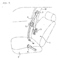
- In the related art, as one of the seatbelt apparatus in the related art, for example, there is a three-point type seatbelt apparatus as shown in Fig. 9. In the drawing,
reference numeral 1 designates a seatbelt apparatus provided on a vehicle seat 2,reference numeral 3 designates a seatbelt retractor fixed to a vehicle body near the vehicle seat 2 for constantly urging a seatbelt 4 so as to be withdrawably retracted, and locking the seatbelt 4 from being withdrawn in case of emergency,reference numeral 5 designates a tongue slidably supported by the seatbelt 4,reference numeral 6 designates a buckle located on the side of the vehicle seat 2 and fixed to the vehicle seat 2 or the vehicle body for being engaged by thetongue 5, andreference numeral 7 designates a belt guide mounted to an upper side of a vehicle side portion such as a center pillar 8 for guiding the seatbelt 4 withdrawn from the seatbeltretractor 3. Abelt anchor portion 4a at a distal end of the seatbelt 4 withdrawn from the seatbeltretractor 3 is fixed to the vehicle seat 2 or the vehicle body. - With the
seatbelt apparatus 1 configured as described above, when the passenger attaches the seatbelt 4, the passenger sits on the vehicle seat 2, withdraws the seatbelt 4 from theseatbelt retractor 3, engages thetongue 5 with thebuckle 6, and then releases his/her hand from thetongue 5, whereby the part of the seatbelt 4 excessively withdrawn is retracted by theseatbelt retractor 3 and hence a slack of the seatbelt is removed, and the seatbelt 4 is attached to the passenger. In this case, the seatbelt 4 between thebelt guide 7 and thetongue 5 functions as ashoulder belt 4b for constraining the shoulder and the chest of the passenger, and the seatbelt 4 between thebelt anchor portion 4a fixed to the vehicle body and thetongue 5 functions as alap belt 4c for constraining a lap (lumber) of the passenger. - Then, in case of emergency such as the vehicle collision of where a significantly large deceleration is applied to the vehicle, an emergency locking mechanism of the
seatbelt retractor 3 is activated to lock the seatbelt 4 from being withdrawn and prevent the forward movement of the passenger by a force of inertia, whereby the passenger is constrained and protected. In particular, in the recent years, the pretensioner is provided in theseatbelt retractor 3, thebelt anchor portion 4a, or the buckle or the like so that the pretensioner is activated in case of occurrence of emergency and pulls the seatbelt 4 to remove the slack of the seatbelt 4 quickly so that the forward movement of the passenger is kept as little as possible, whereby the effects of constraining and protecting the passenger are improved. - As the seatbelt apparatus provided with the pretensioner as described above, there is proposed a seatbelt apparatus in which the pretensioners are provided in the seatbelt retractor and the belt anchor portion respectively, so that the pretensioner in the seatbelt retractor is activated first in case of emergency to retract the seatbelt by the seatbelt retractor, and then the pretensioner of the belt anchor portion is activated to pull the seatbelt and remove the slack of the seatbelt quickly for constraining the passenger (for example, see Patent Document 1).
- In the seatbelt apparatus disclosed in
JP-A-2001-287622 - However, in the seatbelt apparatus disclosed in
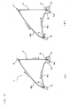
Patent Document 1, when afirst pretensioner 9 of theseatbelt retractor 3 is activated and the seatbelt 4 is retracted by theseatbelt retractor 3 as shown in Fig. 10(a), both of theshoulder belt 4b and thelap belt 4c are pulled toward theseatbelt retractor 3 as indicated by an arrow A. Subsequently, asecond pretensioner 10 of thebelt anchor portion 4a is activated and hence the seatbelt 4 is pulled toward thebelt anchor portion 4a as shown in Fig. 10(b), both of thelap belt 4c and theshoulder belt 4b are pulled toward thebelt anchor portion 4a as indicated by an arrow B. Therefore, even though thelap belt 4c is pulled by thefirst pretensioner 9 and a slack of thelap belt 4c is removed, theshoulder belt 4b is pulled with thelap belt 4c in the opposite direction by thesecond pretensioner 10, and hence thelap belt 4c is loosened. Therefore, since thelap belt 4c which functions for constraining the passenger most is loosened, the effect of constraining the passenger cannot be sufficiently achieved. - In view of such circumstances, it is an object of the present invention to provide a seatbelt apparatus in which removal of the slack of the lap belt is ensured even though the two pretensioners are activated under two time frames, whereby the effects of constraining the passenger are satisfactorily achieved.
- In order to achieve the above-described object, a seatbelt apparatus according to
Claim 1 includes at least a seatbelt including a shoulder belt for constraining an upper half body of a passenger and a lap belt for constraining a lumber of the passenger, a seatbelt retractor for withdrawably retracting the seatbelt and locking the seatbelt from being retracted in case of emergency, a belt anchor portion for fixing a distal end of the seatbelt withdrawn from the seatbelt retractor to a vehicle body, a tongue slidably supported by the seatbelt and partitioning between the shoulder belt and the lap belt, a buckle fixed to the vehicle body and capable of being engaged by the tongue, first and second pretensioners provided in any two of the seatbelt retractor, the belt anchor portion and the buckle for activating and pulling the seatbelt in case of emergency, the first and second pretensioners being adapted to be activated under two time frames in such a manner that the second pretensioner is activated after having activated the first pretensioner, and a belt one-way movement preventing means for preventing the shoulder belt from moving toward the lap belt when the second pretensioner is activated. - The invention according to Claim 2 is characterized in that the tongue is a one-way tongue which prevents the shoulder belt from moving toward the lap belt when a predetermined pulling force toward the shoulder belt is applied to the seatbelt and, in this state, a force larger than the predetermined pulling force is applied to the seatbelt in the direction toward the lap belt, and the belt one-way movement preventing means is the one-way tongue.
- According to the seatbelt apparatus configured as in
Claims 1 and 2 of the invention, when there is a probability that the shoulder belt moves toward the lap belt when the second pretensioner is activated subsequently, the belt one-way movement preventing means prevents the shoulder belt from moving toward the lap belt. Therefore, removal of the slack of the lap belt is ensured. Accordingly, the lumber of the passenger can be firmly constrained by the lap belt, and the effects of constraining the passenger are satisfactorily achieved. - In particular, according to Claim 2 of the invention, since the one-way tongue is used as the belt one-way movement preventing means, it is not necessary to provide specific parts as the belt one-way movement preventing means, and hence the number of parts can be reduced, and the structure can be simplified. In addition, the seatbelt apparatus can be manufactured at a lower cost.
- Referring now to the drawings, a best mode for carrying out the present invention will be described.
- Fig. 1 is a schematic drawing of an example of an embodiment of a seatbelt apparatus of the present invention. Fig. 1(a) is an explanatory drawing showing a state in which a pretensioner of a seatbelt retractor is activated, and Fig. 1(b) is an explanatory drawing showing a state in which a pretensioner of a belt anchor portion is activated;
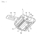
- Fig. 2 is an exploded perspective view showing an example of the embodiment of the tongue in the seatbelt apparatus according to the present invention;
- Fig. 3 shows a tongue plate in the example in Fig. 2, in which Fig. 3(a) is a front view, Fig. 3(b) is a right side view, and Fig. 3(c) is a top view;
- Fig. 4 shows a webbing guide in the example in Fig. 2, in which Fig. 4(a) is a front view, Fig. 4(b) is a right side view, and Fig. 4(c) is a bottom view;
- Fig. 5 shows a lock bar in the example in Fig. 2, in which Fig. 5(a) is a front view, Fig. 5(b) is a right side view, and Fig. 5(c) is a top view;
- Fig. 6 shows a bar spring in the example in Fig. 2, in which Fig. 6(a) is a front view, Fig. 6(b) is a right side view, Fig. 6(c) is a top view, and Fig. 6(d) is a perspective view;
- Fig. 7 is a perspective view of the tongue shown in the example in Fig. 2;
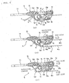
- Fig. 8 explains the operation of the tongue shown in the example in Fig. 2; Fig. 8(a) is a cross-sectional view showing a state of the tongue in the stored position when a seatbelt is not attached; Fig. 8(b) is a cross-sectional view showing the state of the tongue when the seatbelt is attached and the pretensioner is activated; and Fig. 8(c) is a cross-sectional view showing the state of the tongue when the seatbelt is attached and after the pretensioner is activated;
- Fig. 9 is a perspective view showing a general three-point type seatbelt apparatus in the related art schematically; and
- Fig. 10 shows an example of the seatbelt apparatus provided with pretensioners in the related art schematically, in which Fig. 10(a) is an explanatory drawing showing a state in which the pretensioner of a seatbelt retractor is activated, and Fig. 10(b) is an explanatory drawing showing a state in which the pretensioner in the belt anchor portion is activated.
The same parts as aseatbelt apparatus 1 in the related art described above shown in Fig. 9 and Fig. 10 are represented by the same reference numerals, and detailed description is omitted. - As shown in Fig. 1(a), the
seatbelt apparatus 1 in this example is configured as the general three-point type seatbelt apparatus in the related art described above in such a manner that the abelt anchor portion 4a at one end of a seatbelt 4 for constraining a passenger is fixed to a vehicle body, and the other end of the seatbelt 4 is guided by abelt guide 7 mounted to an upper portion of the vehicle body such as a center pillar, and then withdrawably retracted by aseatbelt retractor 3 fixed to a lower portion of the vehicle body, and atongue 5 slidably supported by the seatbelt 4 between thebelt anchor portion 4a and thebelt guide 7 is engaged with abuckle 6 fixed to the vehicle body or the like, whereby the passenger seated on a vehicle seat is constrained. - The
tongue 5 used in theseatbelt apparatus 1 in this example is formed of a one-way tongue (which corresponds to a belt one-way movement preventing means in the present invention). This one-way tongue is adapted in such a manner that thetongue 5 allows free passage of the seatbelt 4 in either directions. When a predetermined pulling force toward theseatbelt retractor 3 is applied to ashoulder belt 4b and, in this state, a pulling force which is larger than the predetermined pulling force is applied to thelap belt 4c in the direction toward thebelt anchor portion 4a, the one-way tongue catches and locks the seatbelt 4 to prevent theshoulder belt 4b from moving toward alap belt 4c, and allow thelap belt 4c to move toward theshoulder belt 4b. - In the
seatbelt apparatus 1 in this example, a tongue proposed inJapanese Patent Application No.2004-375760
Fig. 2 is an exploded perspective view showing the tongue proposed inJapanese Patent Application No. 2004-375760
As shown in Fig. 2, thetongue 5 includes atongue body 13 having ametallic tongue plate 11 and atongue mold 12 which covers thetongue plate 11 partly with resin, awebbing guide 14 provided on thetongue body 13 so as to be capable of relative rotation, a revolvingshaft 15 set across thetongue body 13 by being fitted into a pair ofmounting holes tongue body 13 and a throughhole 14a of thewebbing guide 14 respectively for rotatably supporting thewebbing guide 14, alock bar 16 supported by thewebbing guide 14 so as to be capable of relative rotation, a pair of revolvingshafts lock bar 16 by being fitted into a throughhole 14b of thewebbing guide 14 and a pair ofmounting holes lock bar 16, and abar spring 19 mounted respectively to thetongue mold 12 and thelock bar 16 for urging thelock bar 16 constantly in one direction. - Fig. 3 shows the
tongue plate 11. Fig. 3(a) is a front view, Fig. 3(b) is a right side view, and Fig. 3(c) is a top view.
As shown in Figs. 3(a) to 3(c), thetongue plate 11 is formed of a substantially T-shaped metallic plate having a laterally extendingportion 11a and a vertically extendingportion 11b extending integrally and vertically from a center portion of the laterally extendingportion 11a. The laterally extendingportion 11a is formed with a largesquare opening 11c extending in the lateral direction, and the vertically extendingportion 11b is formed with asquare opening 11d extending in the vertical direction. The opening 11d in the vertical direction is adapted so that a latch member of thebuckle 6, not shown, engages like general tongues in the related art. Therefore, the vertically extendingportion 11b is configured as an engaging strip which engages with thetongue 5. Hereinafter, the vertically extendingportion 11b is also referred to as theengaging strip 11b. - A pair of
side walls portion 11a. Theside walls holes 11g, 11h of the same size. The pair ofside walls recessed grooves recessed groove 11i is formed into T-shape with alateral groove 11i1 opening to an outer peripheral edge of theside wall 11e and avertical groove 11i2 in communication with thelateral groove 11i1. The otherrecessed groove 11j has the same shape as therecessed groove 11i, and is formed into the T-shape with alateral groove 11j1 and avertical groove 11j2 (Reference numerals - As shown in Fig. 2, almost all part of the laterally extending
portion 11a of thetongue plate 11 is molded with resin, and then thetongue mold 12 is formed. In this case, by molding an inner peripheral surface of the pair ofholes 11g, 11h with resin, the above-described pair ofmounting holes shaft 15 are formed. Also, by closing a right end of therecessed groove 11i in Fig. 3(a) and a left end of therecessed groove 11j in Fig. 3(a) with mold resin respectively and molding an inner peripheral surface of the pair ofrecessed grooves guide grooves guide grooves 13d is formed into the T-shape with avertical groove 13d1 opening upward and alateral groove 13d2 communicating with thelateral groove 13d1. Theother guide groove 13c has the same shape as theguide groove 13d and is formed into the T-shape with avertical groove 13c1 and alateral groove 13c2 communication with thevertical groove 13c1. (Reference numeral 13c2 is not shown, but corresponds to thereference numeral 13d2, and is used for convenience of explanation). Furthermore, by molding an inner peripheral surface of the opening 11c of thetongue plate 11 with resin, a large square opening 13e is formed on thetongue body 13. - Fig. 4 shows the
webbing guide 14. Fig. 4(a) is a front view, Fig. 4(b) is a right side view, and Fig. 4(c) is a bottom view.
As shown in Figs. 4(a) to 4(c), thewebbing guide 14 is formed into a substantially square shape in lateral cross-section, and is provided with a relativelylong guide body 14c having four corners rounded into R portions having a large diameter. Foursurfaces square guide body 14c respectively are formed into curved surfaces which swell slightly outward. At least one side of these four sides may be formed as a linear plate. - On one
surface 14c1 of theguide body 14c facing downward in Fig. 2 is formed with a predetermined number (seven in the example shown in the drawing) of square shapedrecesses 14d. The above-described throughhole 14a is provided in theguide body 14c so as to penetrate therethrough in the longitudinal direction. Anothersurface 14c4 of theguide body 14c is formed with a mountingmember 14e integrally along the longitudinal direction of theguide body 14c. Then, the above-described throughhole 14b is formed on the mountingmember 14e so as to penetrate in the longitudinal direction.
A boundary including a corner between thesurface 14c1 of theguide body 14c and thesurface 14c2 continuing from thesurface 14c1 and facing upward corresponds to awebbing guide portion 14f for guiding the seatbelt 4 on the input side of the seatbelt 4. Furthermore, thesurface 14c4 of theguide body 14c functions as a stopper as described later. - The revolving
shaft 15 for rotatably supporting thewebbing guide 14 on thetongue body 13 is adapted to function also as a strength retaining member which can support a pulling force of a large magnitude which is applied to the seatbelt 4 in case of emergency. - Fig. 5 shows the
lock bar 16. Fig. 5(a) is a front view, Fig. 5(b) is a right side view, and Fig. 5(c) is a top view.
As shown in Figs. 5(a) to 5(c), thelock bar 16 is provided with alock body 16c of substantially square shape in lateral cross-section. Thelock body 16c is provided at both ends thereof withguide shafts guide shafts guide grooves tongue body 13 so as to be capable of moving, whereby guiding thelock body 16c. Thelock body 16c is integrally provided at both ends thereof with mountingmembers members member 14e of thewebbing guide 14 between the mountingmembers holes members lock body 16c is formed at both ends thereof with mountingholes - Fig. 6 shows the
bar spring 19. Fig. 6(a) is a front view, Fig. 6(b) is a right side view, Fig. 6(c) is a top view, and Fig. 6(d) is a perspective view.
As shown in Figs. 6(a) to 6(d), thebar spring 19 is formed of a resilient wire member, and is formed into a relatively complicated shape in laterally symmetry shown in Figs. 6(a) and 6(c). In other words, thebar spring 19 includes, in sequence from a right side of afirst portion 19a at a center toward a right end, asecond portion 19b bent in the vertical direction at a right angle, athird portion 19c bent from thesecond portion 19b at a right angle with respect to both of the first andsecond portions fourth portion 19d bent from thethird portion 19c toward thesecond portion 19b so as to extend in parallel with thesecond portion 19b and at right angle with respect to thethird portion 19c, afifth portion 19e bent from thefourth portion 19d toward an opposite side from thefirst portion 19a so as to extend in parallel with thefirst portion 19a and at a right angle with respect to thefourth portion 19d, and asixth portion 19f bent from thefifth portion 19e toward an opposite side from thefirst portion 19a at a right angle with respect to thefifth portion 19e. Thebar spring 19 also includes, on a left side of thefirst portion 19a at the center thereof, asecond portion 19g, athird portion 19h, afourth portion 19i, afifth portion 19j, and asixth portion 19k corresponding to the respective portions on the right side. - The
bar spring 19 is adapted to be mounted in such a manner that thefirst portion 19a at the center thereof is fitted into and supported by aspring supporting portion 12a which is constituted of a recessed groove of thetongue mold 12 shown in Fig. 2, and left and rightsixth portions holes lock bar 16 respectively. - The
tongue 5 of this example in such a structure is assembled, for example, as shown below. The mountingmember 14e of thewebbing guide 14 is positioned between the mountingmembers lock bar 16, the revolvingshafts holes lock bar 16 respectively and the throughhole 14b of thewebbing guide 14, and thelock bar 16 is mounted to the mountingmember 14e on the output side of thewebbing guide 14 so as to be capable of relative rotation. The respectivesixth portions bar spring 19 are fitted into the mountingholes lock bar 16, and thebar spring 19 is mounted to thelock bar 16. - Then, as shown in Fig. 7, the
webbing guide 14 is placed between left andright side walls tongue mold 12 in such a manner that thewebbing guide portion 14f faces toward the engagingstrip 11b, and the revolvingshaft 15 is fitted into the mountingholes tongue body 13 and the throughhole 14a of thewebbing guide 14, whereby thewebbing guide 14 is mounted to thetongue body 13 so as to be capable of relative rotation. Also, the left andright guide shafts lock bar 16 are passed through thevertical grooves lateral groves guide grooves - Finally, the
first portion 19a at the center of thebar spring 19 is fitted to the recessed groove of thespring supporting portion 12a of thetongue mold 12. At this time, theguide shafts lock bar 16 are pressed leftward in Fig. 8(a) by an urging force of thebar spring 19 and moved leftward along thelateral grooves guide groove tongue mold 12. Simultaneously, since a clockwise moment about the revolvingshaft 15 is applied to thewebbing guide 14 and thelock bar 16 by the urging force of thebar spring 19, thewebbing guide 14 and thelock bar 16 rotate clockwise about the revolvingshaft 15. In this case, since the position of the revolvingshaft 15 is fixed, theguide shafts shaft 15. Therefore, as shown in Fig. 8(a), thewebbing guide 14 and thelock bar 16 rotate with a bending movement with respect to each other so that the centers of the revolvingshafts shaft 15 and the centers of theguide shafts - Then, the
lock bar 16 comes into abutment with a stopper constituted by the onesurface 14c4 of thewebbing guide 14 so that further bending movement with respect to thewebbing guide 14 is prevented, and is kept in a state of being bent at substantially a right angle. When theguide shafts lateral groove guide grooves guide shafts tongue 5 is assembled in a state in which thewebbing guide 14 and thelock bar 16 are maintained in initial positions as shown in Fig. 8(a) . - In this manner, in a state in which the
webbing guide 14 and thelock bar 16 are maintained in the initial positions shown in Fig. 8(a), a gap α is defined between thewebbing guide portion 14f of thewebbing guide 14 and aportion 12d of thetong mold 12 opposing to thewebbing guide portion 14f, and a gap β is defined between a corner of thelock body 16c of thelock bar 16 and aportion 12e of thetongue mold 12 opposing this corner. These gaps α, β are set to maximum values significantly larger than the thickness of the seatbelt 4 in a state shown in Fig. 8(a). Therefore, when thetongue 5 is supported by the seatbelt 4 so that the seatbelt 4 passes through the gap α and is guided by thewebbing guide 14, and then passes through the gap β, thetongue 5 slides with respect to the seatbelt 4 smoothly without little resistance. In addition, since the seatbelt 4 guided by thewebbing guide 14 through theopening 13e of thetongue body 13 does not interfere with thetongue mold 12 of thetongue body 13, thetongue 5 slides further smoothly with respect to the seatbelt 4. When the gap α is too large, reversal of the seatbelt 4 may be resulted easily, and hence the gap α is set to an extent that does not cause the reversal of the seatbelt 4. - When a force larger than a predetermined magnitude which causes a counterclockwise moment about the revolving
shaft 15 is applied to thewebbing guide 14, thewebbing guide 14 rotates counterclockwise against the moment generated by the urging force of thebar spring 19. Then, by the rotation of thewebbing guide 14, theguide shafts guide grooves tongue mold 12 while thelock bar 16 rotates clockwise about theguide shafts lock bar 16, the seatbelt 4 is caught between the corner of thelock body 16c and theportion 12e of thetongue mold 12 and is locked. - In other words, the two pieces of the
webbing guide 14 and thelock bar 16 constitute a lap belt extension preventing means for preventing extension of thelap belt 4c by locking the seatbelt 4 in case of emergency. In this case, by the rotation and the linear movement of thelock bar 16, even when the amount of rotation of thelock bar 16 is relatively reduced while increasing the amount of rotation of thewebbing guide 14, the sufficient amount of the linear movement of thelock bar 16 is secured. - Subsequently, the operation of the
tongue 5 in this example will be described.
When the seatbelt 4 is not attached as shown in Fig. 8(a), the seatbelt 4 is retracted by theseatbelt retractor 3, not shown, and thetongue 5 assumes a stored state. In the stored state of thetongue 5 , thewebbing guide 14 and thelock bar 16 are retained in the initial positions shown in Fig. 8(a) by the urging force of thebar spring 19 and the stopper (thefirst surface 14c4 of theguide body 14c) and the both gaps α, β are set to the maximum value as described above. Therefore, thetongue 5 is smoothly slidable with respect to the seatbelt 4. - In order to attach the seatbelt 4, the passenger withdraws the
tongue 5 from the stored position and inserts theengaging strip 11b of thetongue 5 into thebuckle 6 on the opposite side. At this time, since the seatbelt 4 is withdrawn from theseatbelt retractor 3, and thewebbing guide 14 and thelock bar 16 do not rotate and are maintained at the initial positions, thetongue 5 slides smoothly with respect to the seatbelt 4. When the passenger engages thetongue 5 with thebuckle 6, and then releases thetongue 5, the excessively withdrawn seatbelt 4 is retracted by theseatbelt retractor 3, and hence the seatbelt 4 fits the passenger without giving a feeling of pressure, and thetongue 5 assumes the state shown in Fig. 8(b). In the state shown in Fig. 8(b), since a retracting force of theseatbelt retractor 3 is applied to the seatbelt 4, the seatbelt 4 is maintained in the state of being pulled lightly toward the shoulder (SHO side) of the passenger. Therefore, thewebbing guide 14 and thelock bar 16 are maintained in the initial positions. In this state, the seatbelt 4 is in abutment with thewebbing guide portion 14f, and is also in abutment with the mountingmember 14e of thewebbing guide 14. - In case of emergency such as vehicle collision or the like where a significantly large deceleration is applied to a vehicle, when the pretensioner, not shown, provided in the
seatbelt retractor 3 is activated, the seatbelt 4 is quickly retracted by theseatbelt retractor 3, and the seatbelt 4 is pulled toward the SHO side further strongly. Therefore, thewebbing guide 14 and thelock bar 16 are still maintained in the initial positions. - When the operation of the pretensioner is ended, the seatbelt 4 is pulled toward the lumber of the passenger (LAP side) strongly by a force of inertia toward the front at the lumber (LAP) of the passenger. Since the pulling force of the seatbelt 4 toward the LAP side acts on the
webbing guide portion 14f and the mountingmember 14e of thewebbing guide 14 and a counterclockwise large moment about the revolvingshaft 15 is applied to thewebbing guide 14, thewebbing guide 14 rotates counterclockwise about the revolvingshaft 15. Simultaneously, theguide shafts lateral grooves guide grooves tongue mold 12 while thelock bar 16 rotates clockwise about theguide shafts - Due to the counterclockwise rotation of the
webbing guide 14 and the clockwise rotation and the linear movement of thelock bar 16, the corner of thelock body 16c of thelock bar 16 approaches theportion 12e of thetongue mold 12 and the gap β is reduced. Accordingly, as shown in Fig. 8(c), the seatbelt 4 is caught between the corner of thelock body 16c and theportion 12e of thetongue mold 12. In this case, since the sufficient amount of linear movement is secured even when the amount of rotation is small because of the rotation and the linear movement of thelock bar 16, the significantly large force is generated to catch the seatbelt 4. - In addition, in a state in which the seatbelt 4 is caught between the corner of the
lock body 16c and theportion 12e of thetongue mold 12, the centers of the revolvingshafts webbing guide 14 and thelock bar 16 are located at positions slightly upper than the straight line connecting the center of the revolvingshaft 15 and the centers of theguide shafts bar spring 19 urges thewebbing guide 14 and thelock bar 16 about the revolvingshaft 15 so as to rotate counterclockwise. In other words, the force to catch the seatbelt 4 by the corner of thelock body 16c and theportion 12e of thetongue mold 12 is increased to a further large force by the pulling force of the seatbelt 4 toward the LAP side and the urging force of thebar spring 19. Therefore, the seatbelt 4 is firmly caught by the corner of thelock body 16c and theportion 12e of thetongue mold 12 and hence locking of the seatbelt 4 by thelock bar 16 is reliably achieved. Therefore, sliding movement of the seatbelt 4 between the corner of thelock body 16c and theportion 12e of thetongue mold 12, and hence extension of the seatbelt 4 is prevented, whereby constraint of the passenger by the seatbelt 4 is ensured.
Other structures and other operations of theseatbelt apparatus 1 in this example are the same as the example shown in Fig. 9 and Fig. 10 described above. - In the
seatbelt apparatus 1 in this example, when afirst pretensioner 9 of theseatbelt retractor 3 is activated and the seatbelt 4 is retracted by theseatbelt retractor 3, both of theshoulder belt 4b and thelap belt 4c are pulled toward theseatbelt retractor 3 as shown by an arrow in Fig. 1(a). Then, asecond pretensioner 10 of thebelt anchor portion 4a is activated, and the seatbelt 4 is pulled toward thebelt anchor portion 4a as shown in Fig. 1(b). At this time, since thetongue 5 is constructed as the above-described one-way tongue, when thesecond pretensioner 10 is activated in a state in which both of theshoulder belt 4b and thelap belt 4c are pulled toward theseatbelt retractor 3 by a predetermined pulling force by the operation of thefirst pretensioner 9, and hence thelap belt 4c is pulled toward thebelt anchor portion 4a by a pulling force larger than the predetermined pulling force as shown by an arrow B, thetongue 5 catches and locks the seatbelt 4. Accordingly, when thelap belt 4c is pulled toward thebelt anchor portion 4a, theshoulder belt 4b does not move toward thelap belt 4c through thetongue 5. Therefore, removal of a slack of thelap belt 4c is ensured, and hence the lumber of the passenger is securely constrained. - According to the
seatbelt apparatus 1 in this example, when the two pretensioners are activated under two time frames in such a manner that thepretensioner 9 of theseatbelt retractor 3 is activated first and then thepretensioner 10 of thebelt anchor portion 4a is activated, thetongue 5 prevents theshoulder belt 4b from moving toward thelap belt 4c, removal of the slack of thelap belt 4c is ensured. Accordingly, the lumber of the passenger by thelap belt 4c can be constrained firmly, and hence the effects of constraining the passenger can be sufficiently achieved.
Since thetongue 5 which is composed of the one-way tongue is used as the belt one-way movement preventing means, it is not necessary to provide specific parts as the belt one-way movement preventing means, and hence the number of parts can be reduced, and the structure can be simplified and, in addition, theseatbelt apparatus 1 can be manufactured at a low cost. - In the example described above, the two
pretensioners seatbelt retractor 3 and thebelt anchor portion 4a. However, in the present invention, the twopretensioners seatbelt retractor 3, thebelt anchor portion 4a, and thebuckle 6. In this case, if there is a probability that theshoulder belt 4b moves toward thelap belt 4c when the second pretensioner is activated, the movement of theshoulder belt 4b toward thelap belt 4c can be prevented by the belt one-way movement preventing means. Even when there is a probability that thelap belt 4c moves toward theshoulder belt 4b when the second pretensioner is activated, since it is the direction to remove the slack of thelap belt 4c, the belt one-way movement preventing means can be adapted so as not to prevent the movement of thelap belt 4c toward theshoulder belt 4b. - Although the tongue in the above-described
Japanese Patent Application No. 2004-375760 tongue 5, it is not limited thereto, and other types of one-way tongue can be used as long as it prevents the movement of theshoulder belt 4b toward thelap belt 4c through thetongue 5 when the pretensioner of the second step is activated and hence thelap belt 4c is pulled. It is also possible to constitute the belt one-way movement preventing means with a suitable means other than the tongue. - The tongue of the present invention used for the seatbelt apparatus mounted in the vehicle such as the automotive vehicle for constraining and protecting the passenger by the seatbelt, and can be suitably used as the tongue which is slidably supported by the seatbelt and engages with the buckle.
Claims (2)
- A seatbelt apparatus comprising at least: a seatbelt including a shoulder belt for constraining an upper half body of a passenger and a lap belt for constraining a lumber of the passenger; a seatbelt retractor for withdrawably retracting the seatbelt and locking the seatbelt from being retracted in case of emergency; a belt anchor portion for fixing a distal end of the seatbelt withdrawn from the seatbelt retractor to a vehicle body; a tongue slidably supported by the seatbelt and partitioning between the shoulder belt and the lap belt; a buckle fixed to the vehicle body and capable of being engaged by the tongue; first and second pretensioners provided in any two of the seatbelt retractor, the belt anchor portion and the buckle for activating and pulling the seatbelt in case of emergency, the first and second pretensioners being adapted to be activated under two time frames in such a manner that the second pretensioner is activated after having activated the first pretensioner; and a belt one-way movement preventing means for preventing the shoulder belt from moving toward the lap belt when the second pretensioner is activated.
- The seatbelt apparatus according to Claim 1, characterized in that the tongue is a one-way tongue which prevents the shoulder belt from moving toward the lap belt when a predetermined pulling force toward the shoulder belt is applied to the seatbelt and, in this state, a force larger than the predetermined pulling force is applied to the seatbelt in the direction toward the lap belt, and the belt one-way movement preventing means is the one-way tongue.
Applications Claiming Priority (1)
| Application Number | Priority Date | Filing Date | Title |
|---|---|---|---|
| JP2005110462A JP4562085B2 (en) | 2005-04-07 | 2005-04-07 | Seat belt device |
Publications (2)
| Publication Number | Publication Date |
|---|---|
| EP1710140A1 true EP1710140A1 (en) | 2006-10-11 |
| EP1710140B1 EP1710140B1 (en) | 2008-05-21 |
Family
ID=36617175
Family Applications (1)
| Application Number | Title | Priority Date | Filing Date |
|---|---|---|---|
| EP06004733A Expired - Lifetime EP1710140B1 (en) | 2005-04-07 | 2006-03-08 | Seatbelt apparatus |
Country Status (5)
| Country | Link |
|---|---|
| US (2) | US20060226694A1 (en) |
| EP (1) | EP1710140B1 (en) |
| JP (1) | JP4562085B2 (en) |
| CN (1) | CN100545009C (en) |
| DE (1) | DE602006001240D1 (en) |
Cited By (2)
| Publication number | Priority date | Publication date | Assignee | Title |
|---|---|---|---|---|
| WO2015140341A1 (en) * | 2014-03-19 | 2015-09-24 | Autoliv Development Ab | Buckle tongue |
| US9623837B2 (en) | 2012-11-14 | 2017-04-18 | Volkswagen Aktiengesellschaft | Safety belt device in a motor vehicle |
Families Citing this family (24)
| Publication number | Priority date | Publication date | Assignee | Title |
|---|---|---|---|---|
| GB2414506B (en) * | 2004-05-25 | 2007-12-12 | Autoliv Dev | Improvements in or relating to a safety-belt tongue and a safety-belt arrangement |
| US7370721B2 (en) * | 2004-12-03 | 2008-05-13 | Autoliv Asp, Inc. | Seatbelt tensioning device and method |
| DE102007007702A1 (en) * | 2007-02-12 | 2008-08-14 | Takata-Petri Ag | Safety belt e.g. three-point safety belt, arrangement for motor vehicle, has shoulder segment relieved by movement of movable area in end position such that resulting force applied at shoulder segment is limited |
| ATE474746T1 (en) * | 2007-02-12 | 2010-08-15 | Takata Petri Ag | SEAT BELT ARRANGEMENT FOR A MOTOR VEHICLE |
| US8302995B2 (en) * | 2009-09-11 | 2012-11-06 | Ford Global Technologies, Llc | Method of controlling a four-point occupant restraint belt system |
| US8662537B2 (en) | 2010-12-28 | 2014-03-04 | Toyota Jidosha Kabushiki Kaisha | Seat belt device |
| US8820788B2 (en) * | 2011-05-09 | 2014-09-02 | Tk Holdings Inc. | Occupant restraint system |
| US8840145B2 (en) * | 2012-06-21 | 2014-09-23 | Tk Holdings Inc. | Seat belt system with rollover locking tongue |
| JP5943512B2 (en) * | 2012-07-18 | 2016-07-05 | タカタ株式会社 | Tongue and seat belt device using the same |
| JP5961545B2 (en) * | 2012-12-25 | 2016-08-02 | 株式会社東海理化電機製作所 | Tongue for seat belt device and seat belt device |
| DE102013216326A1 (en) | 2013-08-16 | 2015-02-19 | Volkswagen Aktiengesellschaft | Seat belt device in a vehicle |
| US9139159B1 (en) * | 2014-07-22 | 2015-09-22 | GM Global Technology Operations LLC | Vehicle and a locking assembly for a seat belt |
| DE102014114207B4 (en) * | 2014-09-30 | 2016-11-17 | Autoliv Development Ab | Lock tongue with a guide portion having a clamping element |
| DE102014017788B4 (en) * | 2014-12-03 | 2020-03-26 | Trw Automotive Gmbh | Tongue |
| US10525929B2 (en) | 2018-02-27 | 2020-01-07 | Ford Global Technologies, Llc | Seatbelt assembly |
| US10434976B2 (en) | 2018-02-27 | 2019-10-08 | Ford Global Technologies, Llc | Seatbelt assembly |
| US10543806B2 (en) | 2018-02-27 | 2020-01-28 | Ford Global Technologies, Llc | Seatbelt assembly |
| US10518740B2 (en) | 2018-02-27 | 2019-12-31 | Ford Global Technologies, Llc | Seatbelt assembly |
| USD1024728S1 (en) * | 2018-05-14 | 2024-04-30 | Radio Systems Corporation | Seatbelt tongue |
| EP3569453B1 (en) * | 2018-05-16 | 2020-10-21 | Volvo Car Corporation | Vehicle seatbelt arrangement |
| US11254282B2 (en) | 2019-01-07 | 2022-02-22 | Joyson Safety Systems Acquisition Llc | Cinch locking tongue for a vehicle occupant restraint system |
| DE102019109697A1 (en) * | 2019-04-12 | 2020-10-15 | Trw Automotive Gmbh | Tongue for a seat belt |
| CN112477799B (en) * | 2020-11-25 | 2022-08-23 | 河南莱茵汽车制造有限公司 | Comfortable safety belt with alarm function |
| US12071096B2 (en) * | 2022-12-14 | 2024-08-27 | Indiana Mills & Manufacturing, Inc. | Web length adjuster |
Citations (4)
| Publication number | Priority date | Publication date | Assignee | Title |
|---|---|---|---|---|
| US5634664A (en) * | 1993-08-24 | 1997-06-03 | Honda Giken Kogyo Kabushiki Kaisha | Safety seat belt device |
| JP2001287622A (en) | 2000-04-06 | 2001-10-16 | Keihin Corp | Vehicle seat belt pretensioner operating method |
| US20020149191A1 (en) * | 2001-04-12 | 2002-10-17 | Takata Corporation | Seat belt apparatus |
| EP1676760A1 (en) * | 2004-12-27 | 2006-07-05 | Takata Corporation | Tongue and seat belt apparatus employing the same |
Family Cites Families (15)
| Publication number | Priority date | Publication date | Assignee | Title |
|---|---|---|---|---|
| US5100176A (en) * | 1991-05-10 | 1992-03-31 | Trw Vehicle Safety Systems Inc. | Tongue assembly |
| US5138749A (en) * | 1991-08-13 | 1992-08-18 | Trw Vehicle Safety Systems Inc. | Tongue assembly |
| JPH07117542A (en) * | 1993-10-20 | 1995-05-09 | Mitsubishi Motors Corp | Occupant restraint system for vehicle seat |
| JPH07304416A (en) * | 1994-05-10 | 1995-11-21 | Takata Kk | Tongue assembly for seat belt device |
| US5870816A (en) * | 1997-05-19 | 1999-02-16 | Trw Vehicle Safety Systems Inc. | Method of assembling a tongue assembly for use with a seat belt system |
| JP4275244B2 (en) * | 1999-05-06 | 2009-06-10 | オートリブ株式会社 | Seat belt device |
| JP4293685B2 (en) * | 1999-05-28 | 2009-07-08 | オートリブ株式会社 | Seat belt device |
| JP3544322B2 (en) | 1999-07-01 | 2004-07-21 | ダイハツ工業株式会社 | Tongue plate for seat belt device |
| JP2001163179A (en) * | 1999-12-10 | 2001-06-19 | Nsk Ltd | Seat belt equipment |
| JP4608812B2 (en) * | 2001-01-12 | 2011-01-12 | タカタ株式会社 | Seat belt through anchor |
| JP3911189B2 (en) | 2002-04-23 | 2007-05-09 | 本田技研工業株式会社 | Air belt device |
| JP2004090667A (en) * | 2002-08-29 | 2004-03-25 | Takata Corp | Seat belt device |
| JP4290573B2 (en) * | 2003-01-24 | 2009-07-08 | 本田技研工業株式会社 | Vehicle travel safety device |
| JP4290570B2 (en) * | 2003-01-24 | 2009-07-08 | 本田技研工業株式会社 | Vehicle travel safety device |
| EP1447021A1 (en) * | 2003-02-17 | 2004-08-18 | Indiana Mills & Manufacturing, Inc. | Web adjuster device |
-
2005
- 2005-04-07 JP JP2005110462A patent/JP4562085B2/en not_active Expired - Fee Related
-
2006
- 2006-03-08 EP EP06004733A patent/EP1710140B1/en not_active Expired - Lifetime
- 2006-03-08 DE DE602006001240T patent/DE602006001240D1/en not_active Expired - Lifetime
- 2006-04-04 US US11/396,636 patent/US20060226694A1/en not_active Abandoned
- 2006-04-07 CN CN200610074172.9A patent/CN100545009C/en not_active Expired - Fee Related
-
2010
- 2010-04-23 US US12/662,565 patent/US8079616B2/en not_active Expired - Fee Related
Patent Citations (5)
| Publication number | Priority date | Publication date | Assignee | Title |
|---|---|---|---|---|
| US5634664A (en) * | 1993-08-24 | 1997-06-03 | Honda Giken Kogyo Kabushiki Kaisha | Safety seat belt device |
| JP2001287622A (en) | 2000-04-06 | 2001-10-16 | Keihin Corp | Vehicle seat belt pretensioner operating method |
| US20020149191A1 (en) * | 2001-04-12 | 2002-10-17 | Takata Corporation | Seat belt apparatus |
| EP1676760A1 (en) * | 2004-12-27 | 2006-07-05 | Takata Corporation | Tongue and seat belt apparatus employing the same |
| JP2006182103A (en) | 2004-12-27 | 2006-07-13 | Tkj Kk | Tongue and seat belt device using the same |
Non-Patent Citations (1)
| Title |
|---|
| PATENT ABSTRACTS OF JAPAN vol. 2002, no. 02 2 April 2002 (2002-04-02) * |
Cited By (2)
| Publication number | Priority date | Publication date | Assignee | Title |
|---|---|---|---|---|
| US9623837B2 (en) | 2012-11-14 | 2017-04-18 | Volkswagen Aktiengesellschaft | Safety belt device in a motor vehicle |
| WO2015140341A1 (en) * | 2014-03-19 | 2015-09-24 | Autoliv Development Ab | Buckle tongue |
Also Published As
| Publication number | Publication date |
|---|---|
| CN100545009C (en) | 2009-09-30 |
| US8079616B2 (en) | 2011-12-20 |
| JP4562085B2 (en) | 2010-10-13 |
| EP1710140B1 (en) | 2008-05-21 |
| CN1843813A (en) | 2006-10-11 |
| US20100276532A1 (en) | 2010-11-04 |
| JP2006290053A (en) | 2006-10-26 |
| US20060226694A1 (en) | 2006-10-12 |
| DE602006001240D1 (en) | 2008-07-03 |
Similar Documents
| Publication | Publication Date | Title |
|---|---|---|
| EP1710140B1 (en) | Seatbelt apparatus | |
| EP1676760B1 (en) | Tongue and seat belt apparatus employing the same | |
| US9615632B2 (en) | Tongue and seat belt device using same | |
| CN105473391B (en) | Dead bolt | |
| JP5808093B2 (en) | Tongue and seat belt device using the same | |
| EP3167743B1 (en) | Seatbelt buckle apparatus | |
| JP5990538B2 (en) | Rocking tongue | |
| US20180220749A1 (en) | Tongue for seatbelt device | |
| EP1980458A2 (en) | Belt guide anchor and seat belt unit including the same | |
| JP5224827B2 (en) | Tongue and seat belt device using the same | |
| JP6846277B2 (en) | Locking tongue and seatbelt device for seatbelts | |
| CN111511611B (en) | Occupant restraint device for vehicle | |
| EP2604137A1 (en) | Seat belt locking buckle and seat belt apparatus including seat belt locking buckle | |
| JP6483982B2 (en) | Belt insertion tool and seat belt device | |
| JP6355764B2 (en) | Seat belt tongue and seat belt device | |
| JP2016060458A (en) | Belt insertion tool and seat belt device | |
| JP6373249B2 (en) | Rocking tongue | |
| CN113795409B (en) | Buckle locking tongue for vehicle occupant restraint system | |
| WO2005115192A1 (en) | A safety-belt tongue and a safety-belt arrangement | |
| KR101240771B1 (en) | Apparatus for guiding safety-belt | |
| JPS6040370Y2 (en) | seat belt anchor device | |
| CN104884313A (en) | Through anchor | |
| KR200416588Y1 (en) | Buckle device for vehicle seat belt with inertia release | |
| JP4565957B2 (en) | Webbing insertion member | |
| WO2018056084A1 (en) | Tongue and seat belt device |
Legal Events
| Date | Code | Title | Description |
|---|---|---|---|
| PUAI | Public reference made under article 153(3) epc to a published international application that has entered the european phase |
Free format text: ORIGINAL CODE: 0009012 |
|
| AK | Designated contracting states |
Kind code of ref document: A1 Designated state(s): AT BE BG CH CY CZ DE DK EE ES FI FR GB GR HU IE IS IT LI LT LU LV MC NL PL PT RO SE SI SK TR |
|
| AX | Request for extension of the european patent |
Extension state: AL BA HR MK YU |
|
| 17P | Request for examination filed |
Effective date: 20070228 |
|
| AKX | Designation fees paid |
Designated state(s): DE FR GB SE |
|
| GRAP | Despatch of communication of intention to grant a patent |
Free format text: ORIGINAL CODE: EPIDOSNIGR1 |
|
| GRAS | Grant fee paid |
Free format text: ORIGINAL CODE: EPIDOSNIGR3 |
|
| GRAA | (expected) grant |
Free format text: ORIGINAL CODE: 0009210 |
|
| AK | Designated contracting states |
Kind code of ref document: B1 Designated state(s): DE FR GB SE |
|
| REG | Reference to a national code |
Ref country code: GB Ref legal event code: FG4D |
|
| REF | Corresponds to: |
Ref document number: 602006001240 Country of ref document: DE Date of ref document: 20080703 Kind code of ref document: P |
|
| PG25 | Lapsed in a contracting state [announced via postgrant information from national office to epo] |
Ref country code: SE Free format text: LAPSE BECAUSE OF FAILURE TO SUBMIT A TRANSLATION OF THE DESCRIPTION OR TO PAY THE FEE WITHIN THE PRESCRIBED TIME-LIMIT Effective date: 20080821 |
|
| PLBE | No opposition filed within time limit |
Free format text: ORIGINAL CODE: 0009261 |
|
| STAA | Information on the status of an ep patent application or granted ep patent |
Free format text: STATUS: NO OPPOSITION FILED WITHIN TIME LIMIT |
|
| 26N | No opposition filed |
Effective date: 20090224 |
|
| REG | Reference to a national code |
Ref country code: FR Ref legal event code: ST Effective date: 20091130 |
|
| PG25 | Lapsed in a contracting state [announced via postgrant information from national office to epo] |
Ref country code: FR Free format text: LAPSE BECAUSE OF NON-PAYMENT OF DUE FEES Effective date: 20091123 |
|
| PGFP | Annual fee paid to national office [announced via postgrant information from national office to epo] |
Ref country code: GB Payment date: 20130306 Year of fee payment: 8 |
|
| GBPC | Gb: european patent ceased through non-payment of renewal fee |
Effective date: 20140308 |
|
| PG25 | Lapsed in a contracting state [announced via postgrant information from national office to epo] |
Ref country code: GB Free format text: LAPSE BECAUSE OF NON-PAYMENT OF DUE FEES Effective date: 20140308 |
|
| REG | Reference to a national code |
Ref country code: DE Ref legal event code: R082 Ref document number: 602006001240 Country of ref document: DE Representative=s name: VOSSIUS & PARTNER PATENTANWAELTE RECHTSANWAELT, DE Ref country code: DE Ref legal event code: R081 Ref document number: 602006001240 Country of ref document: DE Owner name: JOYSON SAFETY SYSTEMS JAPAN K.K., JP Free format text: FORMER OWNER: TAKATA CORP., TOKIO/TOKYO, JP |
|
| PGFP | Annual fee paid to national office [announced via postgrant information from national office to epo] |
Ref country code: DE Payment date: 20180322 Year of fee payment: 13 |
|
| REG | Reference to a national code |
Ref country code: DE Ref legal event code: R119 Ref document number: 602006001240 Country of ref document: DE |
|
| PG25 | Lapsed in a contracting state [announced via postgrant information from national office to epo] |
Ref country code: DE Free format text: LAPSE BECAUSE OF NON-PAYMENT OF DUE FEES Effective date: 20191001 |