EP2604137A1 - Seat belt locking buckle and seat belt apparatus including seat belt locking buckle - Google Patents
Seat belt locking buckle and seat belt apparatus including seat belt locking buckle Download PDFInfo
- Publication number
- EP2604137A1 EP2604137A1 EP12008202.9A EP12008202A EP2604137A1 EP 2604137 A1 EP2604137 A1 EP 2604137A1 EP 12008202 A EP12008202 A EP 12008202A EP 2604137 A1 EP2604137 A1 EP 2604137A1
- Authority
- EP
- European Patent Office
- Prior art keywords
- seat belt
- tongue
- latch
- buckle
- latch member
- Prior art date
- Legal status (The legal status is an assumption and is not a legal conclusion. Google has not performed a legal analysis and makes no representation as to the accuracy of the status listed.)
- Withdrawn
Links
Images


Classifications
-
- A—HUMAN NECESSITIES
- A44—HABERDASHERY; JEWELLERY
- A44B—BUTTONS, PINS, BUCKLES, SLIDE FASTENERS, OR THE LIKE
- A44B11/00—Buckles; Similar fasteners for interconnecting straps or the like, e.g. for safety belts
- A44B11/25—Buckles; Similar fasteners for interconnecting straps or the like, e.g. for safety belts with two or more separable parts
- A44B11/2503—Safety buckles
- A44B11/2542—Safety buckles actuated by a rotatable element, e.g. combined with other actuating means
-
- B—PERFORMING OPERATIONS; TRANSPORTING
- B60—VEHICLES IN GENERAL
- B60R—VEHICLES, VEHICLE FITTINGS, OR VEHICLE PARTS, NOT OTHERWISE PROVIDED FOR
- B60R22/00—Safety belts or body harnesses in vehicles
-
- Y—GENERAL TAGGING OF NEW TECHNOLOGICAL DEVELOPMENTS; GENERAL TAGGING OF CROSS-SECTIONAL TECHNOLOGIES SPANNING OVER SEVERAL SECTIONS OF THE IPC; TECHNICAL SUBJECTS COVERED BY FORMER USPC CROSS-REFERENCE ART COLLECTIONS [XRACs] AND DIGESTS
- Y10—TECHNICAL SUBJECTS COVERED BY FORMER USPC
- Y10T—TECHNICAL SUBJECTS COVERED BY FORMER US CLASSIFICATION
- Y10T24/00—Buckles, buttons, clasps, etc.
- Y10T24/45—Separable-fastener or required component thereof [e.g., projection and cavity to complete interlock]
- Y10T24/45225—Separable-fastener or required component thereof [e.g., projection and cavity to complete interlock] including member having distinct formations and mating member selectively interlocking therewith
Landscapes
- Engineering & Computer Science (AREA)
- Mechanical Engineering (AREA)
- Automotive Seat Belt Assembly (AREA)
Abstract

Description
- The present invention relates to a seat belt locking buckle that fastens a top end of a seat belt to a vehicle body in order to restrain an occupant in the event of an emergency in which a deceleration greater than a normal deceleration is applied to a vehicle, such as the event of collision (hereinafter simply referred to "in the event of emergency"), and a seat belt apparatus including the seat belt locking buckle.
- Seat belt apparatuses attached to a seat of a vehicle, such as an automobile vehicle, have been designed to restrain an occupant by a seat belt in the event of emergency. Examples of such seat belt apparatuses include a three-point seat belt apparatus, which has been widely known and used. In such widely known three-point seat belt apparatus, a top end of a seat belt withdrawn from a seat belt retractor is secured to a vehicle body.
- To lock the top end of a seat belt to a vehicle body, a seat belt apparatus in which the top end of a seat belt is locked to the vehicle body by latching (engaging) the seat belt locking buckle provided at the top end of the seat belt with a seat belt locking tongue fixed to the vehicle body has been developed (refer to, for example, PTL 1).
- In a seat belt apparatus according to a first embodiment described in PTL 1, the seat belt locking buckle includes a pair of buckle latch members each being formed in a plate shape and rotatably disposed about a pivot axis. The two buckle latch members operate in a scissors manner. In addition, the seat belt locking tongue includes a tongue latch member formed in a plate shape. When the tongue latch member is inserted into the buckle, the pair of buckle latch members latches the tongue latch member using a biasing force of a spring.
- In addition, in a seat belt apparatus according to a second embodiment described in PTL 1, the seat belt locking buckle includes a substantially cylindrical latch member. The latch member is formed so as to extend in a direction perpendicular or substantially perpendicular to a flat movement plane located in a trajectory region in which the tongue latch member moves in the seat belt locking buckle. In addition, the latch member is disposed so as to be rotatable about an axis extending in that direction. The substantially cylindrical latch member is always and directly urged by a biasing force of a torsion spring disposed along the axis direction of the latch member so as to be rotated in a direction toward a latch position of the tongue latch member. In addition, the seat belt locking tongue includes a tongue latch member formed in a plate shape. Under a condition in which the buckle latch member is not latched by the tongue latch member, the buckle latch member is held at a non-latch position by a holding member. If the tongue latch member is inserted into the buckle to activate the holding member, the buckle latch member is rotated to the latch position by the biasing force of the torsion spring. Thus, the buckle latch member and the tongue latch member are latchable with each other.
- [PTL 1]
US 2003/0071453 A1 - In the seat belt apparatus according to a first embodiment described in PTL 1, each of the buckle latch members and the tongue latch members is formed in a plate shape. Accordingly, the thickness of the seat belt locking buckle is relatively reduced. However, since the buckle latch member and the tongue latch member are latched with each other using the thicknesses thereof, it is difficult for the buckle latch member and the tongue latch member to be stably and firmly latched with each other, which is problematic.
- In contrast, in the seat belt apparatus according to a second embodiment described in PTL 1, since the buckle latch member is formed in a cylindrical shape, the buckle latch member and the tongue latch member can be stably and firmly latched with each other. However, since the torsion spring extends along the axis direction of the buckle latch member, the thickness of the seat belt locking buckle is relatively large. In addition, since the buckle latch member is rotated by the biasing force of the torsion spring, it is difficult to smoothly rotate the buckle latch member. Furthermore, even when the buckle latch member is not latched by the tongue latch member, the buckle latch member is always and directly urged in the rotational direction. Therefore, it is difficult to assemble the buckle latch member and the torsion spring, which is problematic.
- Accordingly, the object of the present invention is to provide a seat belt locking buckle capable of being stably and firmly latched by the seat belt locking tongue and reducing the thickness thereof and a seat belt apparatus including such a seat belt locking buckle.
- In addition, another object of the present invention is to provide a seat belt locking buckle that allows a buckle latch member to smoothly rotate and to be easily assembled into the seat belt locking buckle and a seat belt apparatus including such a seat belt locking buckle.
- The present invention provides a seat belt locking buckle as defined in claim 1 and a seat belt apparatus as defined in
claim 9. The dependent claims define preferred embodiments of the present invention. To address the above-described problems, a seat belt locking buckle directly or indirectly mounted on one of a seat belt and a vehicle body is provided. The seat belt locking buckle secures a top end of the seat belt to the vehicle body by latching a seat belt locking tongue mounted directly or indirectly on the other of the seat belt and the vehicle body. The seat belt locking buckle includes a seat belt locking tongue insertion port that allows a tongue latch member of the seat belt locking tongue to be inserted into the seat belt locking buckle, a buckle latch member having a substantially solid cylindrical shape, where the buckle latch member is disposed so as to be rotatable about an axis extending in a direction perpendicular or substantially perpendicular to a plane of the motion of the tongue latch member inserted into the seat belt locking buckle through the seat belt locking tongue insertion port at least between a non-latch position at which the tongue latch member is not latchable by the buckle latch member and a latch position at which the tongue latch member is latchable by the buckle latch member, a latch member rotation control member that disables rotation of the buckle latch member and holds the buckle latch member at the non-latch position when the tongue latch member is not inserted into the seat belt locking buckle and that enables rotation of the buckle latch member when moved by the tongue latch member inserted into the seat belt locking buckle along a plane parallel or substantially parallel to the plane of the motion of the tongue latch member, and a latch-member operating member that moves along a plane parallel or substantially parallel to the plane of the motion of the tongue latch member when the buckle latch member is rotatable and pushes the buckle latch member to rotate the buckle latch member from the non-latch position to the latch position. - In addition, in the seat belt locking buckle according to the present invention, the latch-member operating member is separated from the buckle latch member and does not push the buckle latch member when the tongue latch member is not inserted into the seat belt locking buckle. The latch-member operating member is in contact with the buckle latch member and pushes the buckle latch member when the latch member rotation control member is moved by the tongue latch member inserted into the seat belt locking buckle.
- The seat belt locking buckle according to the present invention further includes a first base and a second base. The first base and the second base are assembled together so that a space that allows the tongue latch member inserted through the seat belt locking tongue insertion port to be inserted thereinto is formed between the first base and the second base. The buckle latch member includes a first latch guide portion and a second latch guide portion by which the assembled first base and second base are sandwiched when the tongue latch member and the buckle latch member are latched together.
- In addition, in the seat belt locking buckle according to the present invention, the latch-member operating member rotates the buckle latch member from the non-latch position to the latch position by coming into contact with the first latch guide portion and pushing the first latch guide portion.
- Furthermore, in the seat belt locking buckle according to the present invention, the latch member rotation control member does not allow the latch-member operating member to be in contact with the first latch guide portion when the tongue latch member is not inserted into the seat belt locking buckle, and the latch member rotation control member causes the latch-member operating member to be in contact with the first latch guide portion when the latch member rotation control member is moved by the tongue latch member.
- In addition, the seat belt locking buckle according to the present invention further includes a cover that contains at least the buckle latch member, the latch member rotation control member, the latch-member operating member, the first base, and the second base, where the cover has the seat belt locking tongue insertion port formed therein, and a latch detection unit that protrudes from the cover to the outside of the cover when the seat belt locking tongue is not latched by the seat belt locking buckle and that retracts into the cover when the seat belt locking tongue is latched by the seat belt locking buckle.
- Furthermore, in the seat belt locking buckle according to the present invention, the latch detection unit is disposed in the latch-member operating member.
Still furthermore, the seat belt locking buckle according to the present invention further includes an ejector that urges the tongue latch member inserted into the seat belt locking buckle in a direction in which the tongue latch member is ejected from the seat belt locking buckle, and the ejector serves as the latch member rotation control member. - In contrast, according to the present invention, a seat belt apparatus includes a seat belt capable of restraining a vehicle occupant, a seat belt retractor that retracts the seat belt therein, a tongue slidably supported by the seat belt, a buckle that allows the tongue to be inserted thereinto and engaged therewith, a seat belt locking buckle directly or indirectly mounted on one of the seat belt and a vehicle body, and a seat belt locking tongue directly or indirectly mounted on the other of the seat belt and the vehicle body, where the seat belt locking tongue is latchable by the seat belt locking buckle. The seat belt locking buckle is the seat belt locking buckle according to any one of the above-described seat belt locking buckles.
- In addition, in the seat belt apparatus according to the present invention, the tongue latch member includes a tongue insertion regulation portion that regulates the length of a portion of the tongue latch member that is inserted into the seat belt locking buckle to a predetermined length.
- Furthermore, in the seat belt apparatus according to the present invention, the tongue insertion regulation portion further functions as a tongue latch member wrong insertion preventing portion that prevents the tongue latch member from being accidentally turned over and inserted.
- Still furthermore, in the seat belt apparatus according to the present invention, the tongue latch member includes a tongue latch member wrong insertion preventing portion that prevents the tongue latch member from being accidentally turned over and inserted.
- Yet still furthermore, in the seat belt apparatus according to the present invention, the seat belt locking buckle includes a tongue latch member wrong insertion prevention portion insertion permitting portion formed in the seat belt locking tongue insertion port, and the tongue latch member wrong insertion prevention portion insertion permitting portion allows the tongue latch member wrong insertion preventing portion to pass therethrough.
- According to the seat belt locking buckle having such a structure of the present invention, when the tongue latch member is not inserted into the seat belt locking buckle, rotation of the tongue latch member is disabled by the latch member rotation control member of the seat belt locking buckle and, thus, the tongue latch member is held at the non-latch position. In contrast, when the tongue latch member is inserted into the seat belt locking buckle, the latch member rotation control member is moved by the tongue latch member along a plane that is parallel or substantially parallel to a plane of the motion of the tongue latch member. Thus, rotation of the buckle latch member is enabled. In this manner, the latch-member operating member moves along a plane that is parallel or substantially parallel to a plane of the motion of the tongue latch member. Accordingly, the latch-member operating member pushes the buckle latch member so that the buckle latch member rotates about an axis that is perpendicular or substantially perpendicular to the plane of the motion of the tongue latch member from the non-latch position to the latch position. Consequently, unlike existing seat belt locking buckles, a torsion spring that is disposed along the thickness direction of the seat belt locking buckle and that urges the buckle latch member in the rotational direction need not be provided and, therefore, the thickness of the seat belt locking buckle can be reduced. In addition, since the tongue latch member is latched by the buckle latch member having a substantially solid cylindrical shape, the buckle latch member and the tongue latch member can be stably and firmly latched together.
- Furthermore, when the tongue latch member is not inserted into the seat belt locking buckle, the latch-member operating member is separated from the buckle latch member and, thus, the latch-member operating member does not push the buckle latch member. In this manner, when the buckle latch member is assembled, the buckle latch member is not urged by the latch-member operating member. Consequently, the buckle latch member can be easily assembled.
- Sill furthermore, when the tongue latch member is inserted into the seat belt locking buckle, the assembled first base and second base are sandwiched by the first latch guide portion and the second latch guide portion of the buckle latch member. Thus, even when, in the event of emergency, a tensional force that is greater than in a normal case is exerted on the assembled first base and second base to spread the assembled first base and second base from each other, the first latch guide portion and the second latch guide portion can effectively prevent the spread of the first base and the second base. That is, the strength of the assembled first base and second base can be reinforced by the buckle latch member.
- Yet still furthermore, the latch detection unit is provided. When the seat belt locking tongue is not latched by the seat belt locking buckle, the latch detection unit protrudes from the cover to the outside of the cover. In contrast, when the seat belt locking tongue is latched by the seat belt locking buckle, the latch detection unit is retracted into the cover. Thus, by visually recognizing whether the latch detection unit protrudes to the outside of the cover, an operator can determine whether the seat belt locking tongue and the seat belt locking buckle are latched together. In particular, by providing the latch detection unit in the latch-member operating member, the structure for detecting a latch condition can be simplified.
- Yet still furthermore, the latch member rotation control member is formed from the ejector that urges the tongue latch member in a direction in which the tongue latch member is ejected from the seat belt locking buckle. Accordingly, the structure for latching the seat belt locking buckle can be simplified.
- Yet still furthermore, according to the present invention, the seat belt apparatus includes the seat belt locking buckle of the present invention that is stably and firmly latchable with the seat belt locking tongue and that can reduce the thickness of the seat belt apparatus is provided. Thus, a vehicle occupant can be effectively restrained by using the seat belt. Furthermore, since a space occupied by the seat belt apparatus is reduced, the seat belt apparatus does not interfere with motion of the occupant in a vehicle compartment.
- Yet still furthermore, according to the seat belt apparatus of the present invention, the tongue insertion regulation portion is provided. By using the tongue insertion regulation portion, the length of a portion of the tongue latch member inserted into the seat belt locking buckle can be controlled to a predetermined length. Accordingly, the seat belt locking buckle and the seat belt locking tongue can be easily and stably latched together.
- Yet still furthermore, according to the seat belt apparatus of the present invention, the langue latch member wrong insertion preventing portion is provided. By using the langue latch member wrong insertion preventing portion, wrong insertion in which the tongue latch member is accidentally turned over and is inserted can be prevented. In this manner, a twisted seat belt cannot be buckled and, therefore, the vehicle occupant can be more reliably restrained. In such a case, by forming the tongue latch member wrong insertion preventing portion from the tongue insertion regulation portion, the structures of the tongue latch member wrong insertion preventing portion and the tongue insertion regulation portion can be simplified.
-
- [
Fig. 1] Fig. 1 is a schematic illustration of a seat belt apparatus including a seat belt locking buckle according to an embodiment of the present invention. - [
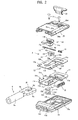
Fig. 2] Fig. 2 is an exploded perspective view of the seat belt locking buckle and a seat belt locking tongue used in the seat belt apparatus illustrated inFig. 1 according to an embodiment of the present invention. - [
Fig. 3] Fig. 3(A) is a top view of a first base;Fig. 3(B) is a cross-sectional view taken along a line IIIB - IIIB ofFig. 3(A); Fig. 3(C) is a front view of the first base; andFig. 3(D) is a perspective view of the first base. - [
Fig. 4] Fig. 4(A) is a top view of a second base;Fig. 4(B) is a front view of the second base; andFig. 4(C) is a bottom view of the second base. - [
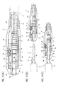
Fig. 5] Fig. 5(A) is a longitudinal cross-sectional view of the seat belt locking buckle according to the embodiment;Fig. 5(B) is a longitudinal cross-sectional view of the seat belt locking buckle with the seat belt locking tongue unlatched; andFig. 5(C) is a longitudinal cross-sectional view of the seat belt locking buckle with the seat belt locking tongue latched. - [
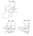
Fig. 6] Fig. 6(A) is a front view of a buckle latch member;Fig. 6(B) is a top view of the buckle latch member;Fig. 6(C) is a bottom view of the buckle latch member; andFig. 6(D) is a right side view of the buckle latch member. - [
Fig. 7] Fig. 7(A) is a front view of an ejector;Fig. 7(B) is a top view of the ejector; andFig. 7(C) is a right side view of the ejector. - [
Fig. 8] Fig. 8(A) is a front view of a slider;Fig. 8(B) is a top view of the slider; andFig. 8(C) is a right side view of the slider. - [
Fig. 9] Fig. 9(A) is a front view of first and second covers;Fig. 9(B) is a bottom view of the first and second covers;Fig. 9(C) is a left side view of the first and second covers;Fig. 9(D) is a front view of a latch member rotating tool for rotating a latch member;Fig. 9(E) is a bottom view of the latch member rotating tool; Fig. 9(F) is a front view of a slider moving tool for moving the slider; and Fig. 9(G) is a bottom view of the slider moving tool. - [
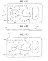
Fig. 10] Fig. 10(A) is a plan view of a seat belt locking tongue;Fig. 10(B) is a cross-sectional view taken along a line XB - XB ofFig. 10(A); and Fig. 10(C) is a right side view of the seat belt locking tongue. - [
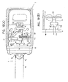
Fig. 11] Fig. 11 illustrates visual check as to whether the seat belt locking tongue is properly latched by the seat belt locking buckle, whereFig. 11(A) is a perspective view of the seat belt locking buckle that is not latched by the seat belt locking tongue,Fig. 11(B) is a cross-sectional view taken along a line XIB - XIB ofFig. 11(A), Fig. 11(C) is a perspective view of the seat belt locking buckle that is properly latched by the seat belt locking tongue, andFig. 11(D) is a cross-sectional view taken along a line XID - XID ofFig. 11(C) . - [
Fig. 12] Fig. 12 is a partially cut-away top view of the seat belt locking buckle with the seat belt locking tongue unlatched. - [
Fig. 13] Fig. 13 is a partially cut-away top view of the seat belt locking buckle with the seat belt locking tongue partially inserted. - [
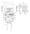
Fig. 14] Fig. 14(A) is a partially cut-away top view of the seat belt locking buckle with the seat belt locking tongue further inserted immediately before the latch member rotates; andFig. 14(B) is a partially enlarged view illustrating a positional relationship between the buckle latch member and the tongue latch member. - [
Fig. 15] Fig. 15(A) is a partially cut-away top view of the seat belt locking buckle after the seat belt locking tongue is further inserted and the latch member is rotated to a latch position; andFig. 15(B) is a partially enlarged view illustrating a positional relationship between the buckle latch member and the tongue latch member. - [
Fig. 16] Fig. 16(A) is a partially cut-away top view of the seat belt locking buckle when the buckle latch member and the tongue latch member are properly latched together; andFig. 16(B) is a partially enlarged view illustrating a positional relationship between the buckle latch member and the tongue latch member. - Embodiments of the present invention are described below with reference to the accompanying drawings.
Fig. 1 is a schematic illustration of a seat belt apparatus including a seat belt locking buckle according to an embodiment of the present invention. - As illustrated in
Fig. 1 , the seat belt apparatus according to the present embodiment is basically similar to a well-known three-point seat belt apparatus. An existing structure of the seat belt apparatus according to the present embodiment is briefly described first. InFig. 1 , a reference numeral "1" denotes the seat belt apparatus, a reference numeral "2" denotes a vehicle seat, a reference numeral "3" denotes a seat belt retractor disposed on the vehicle body in the vicinity of the vehicle seat 2, a reference numeral "4" denotes a seat belt to be withdrawably retracted by the seat belt retractor 3, a reference numeral "5" denotes a seat belt locking buckle attached to a top end of the seat belt 4, a reference numeral "6" denotes a seat belt locking tongue that can be releasably latched by the seat belt locking buckle 5, a reference numeral "7" denotes a pretensioner that allows the seat belt locking tongue 6 to be attached thereto and that operates and exert a tensional force on the seat belt 4 in the event of emergency, a reference numeral "8" denotes a belt guide anchor that leads the seat belt 4 withdrawn from the seat belt retractor 3 to the shoulder of an occupant, a reference numeral "9" denotes a tongue slidably supported by the seat belt 4 lead by the belt guide anchor 8, and a reference numeral "10" denotes a buckle that is fixed to a floor of the vehicle body or the vehicle seat 2 and that allows the tongue 9 to be inserted thereinto and removably engaged therewith. Operations for fastening and unfastening the seat belt 4 of the seat belt apparatus 1 are basically the same as those in existing seat belt apparatuses. - The top end of the seat belt 4 is fixed to the vehicle body by latch-connecting the seat
belt locking buckle 5 to the seatbelt locking tongue 6 fixed to the vehicle body via thepretensioner 7. In addition, when the seat belt 4 is not buckled around an occupant, thetongue 9 is not latched by thebuckle 10. The entire length of the seat belt 4 (more specifically, a length of the seat belt 4 that the seat belt retractor 3 can retract without any problem) is retracted into the seat belt retractor 3. In contrast, in order to buckle the seat belt 4 around an occupant, a predetermined length of the seat belt 4 is withdrawn out of the seat belt retractor 3, as illustrated inFig. 1 . In addition, thetongue 9 is engaged with thebuckle 10, and slack in the seat belt 4 is removed. In this manner, the seat belt 4 is buckled around an occupant. - When the seat belt 4 is buckled around an occupant under a normal condition in which much greater deceleration than that applied to a vehicle traveling on a road is not applied to the vehicle, the seat belt 4 can be freely withdrawn out of the seat belt retractor 3 at a normal belt withdrawal speed. In addition, if the occupant releases the seat belt 4, excessive amounts of slack of the seat belt 4 is retracted into the seat belt retractor 3. Furthermore, when the seat belt 4 is buckled around an occupant in the event of emergency conditions under which a large deceleration is applied to the vehicle (e.g., in the event of collision of the vehicle), the seat belt retractor 3 locks the seat belt 4 so that withdrawal of the seat belt 4 is stopped. In this manner, the seat belt 4 restrains the occupant.
- Structures of the seat belt locking buckle according to the present embodiment and the seat belt apparatus including the seat belt locking buckle that differ from existing structures are described next.
Fig. 2 is an exploded perspective view of the seat belt locking buckle and the seat belt locking tongue of the present invention for use in the seat belt apparatus according to the present embodiment. - As illustrated in
Fig. 2 , according to the present embodiment, the seatbelt locking buckle 5 includes afirst base 11, asecond base 12, abuckle latch member 13, anejector 14, anejector spring 15, aslider 16, aslider guide shaft 17, aslider spring 18, afirst cover 19, asecond cover 20, a pair of assemblingscrews 21, and asheet belt protector 22. In such a case, each of thefirst base 11, thesecond base 12, thebuckle latch member 13, theejector 14, theejector spring 15, theslider 16, theslider guide shaft 17, theslider spring 18, and the pair of assemblingscrews 21 is formed from a metal material. In contrast, each of thefirst cover 19, thesecond cover 20, and thesheet belt protector 22 is formed from a synthetic resin material. -
Fig. 3(A) is a top view of the first base.Fig. 3(B) is a cross-sectional view taken along a line IIIB - IIIB ofFig. 3(A). Fig. 3(C) is a front view of the first base.Fig. 3(D) is a perspective view of the first base.
As illustrated inFigs. 3(A) to 3(D) , thefirst base 11 includes a plate-like base portion 11a and first andsecond side walls base portion 11a upward. Thebase portion 11a includes a seat belt through-hole 11d that allows the seat belt 4 to pass therethrough, a latchmember insertion hole 11e that allows thebuckle latch member 13 to be inserted thereinto, anejector guide hole 11f that leads theejector 14, and an ejectorspring support portion 11g that supports an end of theejector spring 15. - The
first side wall 11b has a firstconcave groove 11h that has a rectangular shape and that opens upward, as illustrated inFig. 3(C) . In addition, the firstconcave groove 11h has first and secondengagement fixing portions engagement fixing portions second base 12 to be engaged therewith and fixed thereto. Furthermore, the firstengagement fixing portion 11i of thefirst side wall 11b has a rectangular firstengagement support groove 11k formed at an end thereof into which the seatbelt locking tongue 6 is to be inserted (a left end portion inFig. 3(C) ). Still furthermore, thefirst side wall 11b has a rectangular secondengagement support groove 11m such that the left end of the rectangular secondengagement support groove 11m is open to the firstconcave groove 11h, as illustrated inFig. 3(C) . The secondengagement support groove 11m is the same as the rectangular firstengagement support groove 11k in shape and size. - In contrast, the
second side wall 11c has a secondconcave groove 11n having a shape and a size that are the same as those of the firstconcave groove 11h. In addition, the secondconcave groove 11n has third and fourthengagement fixing portions engagement fixing portions engagement fixing portions engagement fixing portions second base 12 to be engaged therewith and fixed thereto. Furthermore, the thirdengagement fixing portion 11o of thesecond side wall 11c has a thirdengagement support groove 11q that has a shape and a size that are the same as those of the firstengagement support groove 11k and that is formed in the same manner as the firstengagement support groove 11k. Still furthermore, thesecond side wall 11c has a fourthengagement support groove 11r that has a shape and a size that are the same as those of the secondengagement support groove 11m and that is formed in the same manner as the secondengagement support groove 11m. - In such a case, the first
concave groove 11h, the first and secondengagement fixing portions engagement support groove 11k, and the secondengagement support groove 11m are disposed so as to face the secondconcave groove 11n, the third and fourthengagement fixing portions engagement support groove 11q, and the fourthengagement support groove 11r, respectively, in the width direction of the first base 11 (in the up - down direction inFig. 3(A) ). - In addition, the
first side wall 11b has a latch detection shaft through-hole 11s that allows alatch detection shaft 16c (illustrated inFig. 8 and corresponding to a latch detection unit of the present invention) of theslider 16 to pass therethrough. Thefirst side wall 11b further has afirst fixing hole 11t that allows one end of theslider guide shaft 17 to be fitted and fixed thereto. In addition, thesecond side wall 11c has asecond fixing hole 11u that allows the other end of theslider guide shaft 17 to be fitted and fixed thereto. Still furthermore, thefirst base 11 has first and second screw through-grooves second side walls grooves screws 21 to pass therethrough. -
Fig. 4(A) is a top view of the second base.Fig. 4(B) is a front view of the second base.Fig. 4(C) is a bottom view of the second base.
As illustrated inFigs. 4(A) to 4(C) , thesecond base 12 is formed so as to have a plate shape. Thesecond base 12 includes a seat belt through-hole 12a that allows the seat belt 4 to pass therethrough, a latchmember insertion hole 12b that allows thebuckle latch member 13 to be inserted thereinto, anejector guide hole 12c that leads theejector 14, an ejectorspring support portion 12d that supports an end of theejector spring 15, first and secondfitting holes engagement fixing portions first base 11, respectively, third and fourthfitting holes engagement fixing portions first base 11, respectively, and first and second screw through-holes screws 21 to pass therethrough. - The first to fourth
fitting holes second base 12 are fitted to the first to fourthengagement fixing portions first base 11, respectively. Thereafter, thesecond base 12 is moved in a direction in which the seatbelt locking tongue 6 is inserted with respect to the first base 11 (the right direction inFig. 3(A) ). Thus, first tofourth engagement portions fitting holes second base 12 inFig. 4(A) are fitted into the corresponding first to fourthengagement support grooves first base 11, respectively. In such a case, by inserting the two assemblingscrews 21 through the first and second screw through-holes second base 12 and the first and second screw through-grooves first base 11, a substantive movement of thesecond base 12 relative to thefirst base 11 can be prevented. In this manner, slipping-out of the first tofourth engagement portions second base 12 from the first to fourthengagement support grooves first base 11, respectively, can be prevented. Thus, thesecond base 12 is firmly assembled to thefirst base 11. - When the
second base 12 is assembled to thefirst base 11, a space S having a rectangular shape in lateral cross section is formed between thefirst base 11 and thesecond base 12, as illustrated inFig. 5(A) . In addition, the seat belt through-hole 11d of thefirst base 11 is aligned with the seat belt through-hole 12a of thesecond base 12. The latchmember insertion hole 11e of thefirst base 11 is aligned with the latchmember insertion hole 12b of thesecond base 12. Furthermore, theejector guide hole 11f of thefirst base 11 is substantially aligned with theejector guide hole 12c of thesecond base 12. Still furthermore, the ejectorspring support portion 11g of thefirst base 11 is aligned with the ejectorspring support portion 12d of thesecond base 12. -
Fig. 6(A) is a front view of a buckle latch member.Fig. 6(B) is a top view of the buckle latch member.Fig. 6(C) is a bottom view of the buckle latch member.Fig. 6(D) is a right side view of the buckle latch member.
As illustrated inFigs. 6(A) to 6(D) , thebuckle latch member 13 is formed in a substantially solid cylindrical shape. In addition, thebuckle latch member 13 is supported by thefirst base 11 and thesecond base 12 so as to be rotatable about a rotation axis α of thebuckle latch member 13 between a non-latch position (illustrated inFig. 12 ) and a latch position (illustrated inFig. 16(A) ). The rotation axis α is perpendicular to a plane of the motion of atongue latch member 6b of the seatbelt locking tongue 6 in the seatbelt locking buckle 5. Thebuckle latch member 13 includes abuckle latch portion 13a having a cylindrical shape and formed in the middle thereof, a firstlatch guide portion 13b having an elongated rectangular parallelepiped shape and formed at one end of thebuckle latch portion 13a (the top end inFig. 6(A) ) and a secondlatch guide portion 13c having a disk shape and formed at the other end of thebuckle latch portion 13a (the lower end inFig. 6(A) ). - A circular curved side surface of the
buckle latch portion 13a has a seat belt locking tonguepassage enabling groove 13d (corresponding to a tongue latch member wrong insertion prevention portion insertion permitting portion according to the present invention) formed from a pair of flat planes that are parallel or substantially parallel to each other. The seat belt locking tonguepassage enabling groove 13d extends along the length direction of the firstlatch guide portion 13b. The thickness of the seat belt locking tonguepassage enabling groove 13d (the length in the right - left direction inFig. 6(D) ) is set to much smaller than the diameter of the circular shape of thebuckle latch portion 13a. In contrast, the length of the firstlatch guide portion 13b is set to larger than the circular shape of thebuckle latch portion 13a. Furthermore, the lower surface of the secondlatch guide portion 13c has alatch releasing groove 13e formed in a linear fashion. The central axis of thebuckle latch portion 13a is coaxial with the center of the secondlatch guide portion 13c. The center of the firstlatch guide portion 13b is slightly offset from the central axis of thebuckle latch portion 13a. In such a case, the central axis of thebuckle latch portion 13a is coaxial with the rotation axis α of thebuckle latch member 13. Accordingly, a center of gravity G of thebuckle latch member 13 is significantly close to the rotation axis α of thebuckle latch member 13. - The shape of each of the latch
member insertion hole 11e of thefirst base 11 and the latchmember insertion hole 12b of thefirst base 12 is similar to a planar shape of a plane formed by the firstlatch guide portion 13b and thebuckle latch portion 13a illustrated inFig. 6(B) , and the size of the shape is slightly larger than the planar shape. In such a case, the diameter of a circular arc portion of each of the latchmember insertion holes latch guide portion 13b. Accordingly, the firstlatch guide portion 13b and thebuckle latch portion 13a can pass through each of the latchmember insertion holes buckle latch member 13 is rotated after the firstlatch guide portion 13b passes through each of the latchmember insertion holes latch guide portion 13b cannot pass through each of the latchmember insertion holes latch guide portion 13c is formed so that the diameter of the circular shape thereof is larger than each of the sizes of the latchmember insertion hole 11e of thefirst base 11 and the latchmember insertion hole 12b of thesecond base 12. Thus, the secondlatch guide portion 13c cannot pass through each of the latchmember insertion holes - The planar shape formed by the first
latch guide portion 13b and thebuckle latch portion 13a is aligned with the shape of each of the latchmember insertion holes latch guide portion 13b and thebuckle latch portion 13a pass through the latchmember insertion hole 11e of thefirst base 11 and the latchmember insertion hole 12b of thesecond base 12 from the outer side of thefirst base 11. Subsequently, by rotating thebuckle latch member 13, thebuckle latch member 13 can be relatively rotatably assembled to the assembled first andsecond bases Fig. 5(A) . In such a case, the firstlatch guide portion 13b is located outside of the second base 12 (above thesecond base 12 inFig. 5(A) ). In addition, the secondlatch guide portion 13c is located outside of the first base 11 (under thefirst base 11 inFig. 5(A) ). Furthermore, at least a portion of thebuckle latch portion 13a having the seat belt locking tonguepassage enabling groove 13d formed therein is located in the space S between thefirst base 11 and thesecond base 12. In this manner, thebuckle latch member 13 cannot be removed from thefirst base 11 and thesecond base 12 unless the planar shape formed from the firstlatch guide portion 13b and thebuckle latch portion 13a is aligned with the shape of each of the latchmember insertion holes -
Fig. 7(A) is a front view of the ejector.Fig. 7(B) is a top view of the ejector.Fig. 7(C) is a right side view of the ejector.
Theejector 14 serves as a latch member rotation control member of the present invention. As illustrated inFigs. 7(A) to 7(C) , theejector 14 includes anejector body 14a having a rectangular parallelepiped shape, a latch member/slider control portion 14b disposed above theejector body 14a inFig. 7(A) , and a pair consisting of a firstejector guide surface 14c and a secondejector guide surface 14d disposed between theejector body 14a and the latch member/slider control portion 14b. In addition, theejector body 14a has a seat belt fixingcontact surface 14e with which the seatbelt locking tongue 6 is in contact. - The
ejector body 14a is disposed in large-width portions of theejector guide hole 11f of thefirst base 11 and theejector guide hole 12c of thesecond base 12. In contrast, the firstejector guide surface 14c and the secondejector guide surface 14d are disposed in a small-width portion of theejector guide hole 12c of thesecond base 12 so as to be fitted to both edges of the small-width portion of theejector guide hole 12c slidably in the length direction of theejector guide hole 12c. - The
ejector 14 is disposed so as to be movable in a direction in which the seatbelt locking tongue 6 is inserted or ejected while theejector body 14a of theejector 14 is being led by the large-width portions of theejector guide hole 11f and theejector guide hole 12c and the firstejector guide surface 14c and the secondejector guide surface 14d are being led by the edges on both sides of the small-width portion of theejector guide hole 12c of thesecond base 12. In addition, since the firstejector guide surface 14c and the secondejector guide surface 14d are fitted into the edges on both side of the small-width portion of theejector guide hole 12c of thesecond base 12, theejector 14 is supported in a direction that is perpendicular to the second base 12 (the up - down direction inFig. 5(A) ). - Furthermore, the
ejector 14 is urged in a direction in which the seatbelt locking tongue 6 is ejected by thecompressed ejector spring 15 loaded between the ejectorspring support portion 11g of thefirst base 11 and the ejectorspring support portion 12d of thesecond base 12 at all times. - The latch member/
slider control portion 14b is disposed outside of the second base 12 (above thesecond base 12 inFig. 5(A) ). The latch member/slider control portion 14b includes aslider control portion 14f tilted at a predetermined angle (about 45 degrees in the example illustrated in the drawing) with respect to the direction in which the seatbelt locking tongue 6 is inserted or ejected (the up - down direction inFig. 7(B) ). The latch member/slider control portion 14b further includes a latch memberrotation prevention portion 14g extending in a direction in which theejector 14 moves. -
Fig. 8(A) is a front view of the slider.Fig. 8(B) is a top view of the slider.Fig. 8(C) is a right side view of the slider.
Theslider 16 serves as a latch-member operating member of the present invention. As illustrated inFigs. 8(A) to 8(C) , theslider 16 includes aslider body 16a, a controlledsurface 16b, alatch detection shaft 16c having a cylindrical shape, a sliderspring support portion 16d, a slider guide shaft through-hole 16e, a latchmember pressing portion 16f, and a latch memberrotation prevention portion 16g. Both sides of theslider body 16a are fitted into and fixed to the first fixinghole 11t of thefirst side wall 11b and thesecond fixing hole 11u of thesecond side wall 11c of thefirst base 11. Thus, theslider body 16a is movably supported by theslider guide shaft 17 disposed between the first andsecond side walls slider guide shaft 17 is disposed so as to extend in a direction that is perpendicular or substantially perpendicular to the direction in which the seatbelt locking tongue 6 is inserted into or ejected from the seatbelt locking buckle 5. Accordingly, theslider guide shaft 17 is supported so as to be movable along theslider guide shaft 17. In such a case, theslider guide shaft 17 is disposed along a plane that is parallel or substantially parallel to a plane of the motion of the seatbelt locking tongue 6 when the seatbelt locking tongue 6 is inserted into or ejected from the seatbelt locking buckle 5. Accordingly, theslider 16 moves along a plane that is parallel or substantially parallel to the plane in which theslider guide shaft 17 is disposed. - The controlled
surface 16b is provided on theslider 16 at an inclination angle that is the same or substantially the same as that of theslider control portion 14f of theejector 14. In addition, the controlledsurface 16b can be in contact with theslider control portion 14f of theejector 14. When the seatbelt locking buckle 5 is not latched by the seatbelt locking tongue 6, the controlledsurface 16b of theslider 16 is in contact with theslider control portion 14f of theejector 14. In this manner, the latchmember pressing portion 16f of theslider 16 is not in contact with the firstlatch guide portion 13b of thebuckle latch member 13. Thus, when the seatbelt locking buckle 5 is not latched by the seatbelt locking tongue 6, a biasing force of the slider spring is not exerted on thebuckle latch member 13. In addition, thelatch detection shaft 16c can slidably pass through the latch detection shaft through-hole 11s of thefirst base 11. - Furthermore, the slider
spring support portion 16d supports theslider spring 18 loaded between the sliderspring support portion 16d and thefirst side wall 11b of thefirst base 11 and is urged by the biasing force of theslider spring 18 at all times. Theslider spring 18 is also disposed along a plane that is parallel or substantially parallel to the plane of the motion of the seatbelt locking tongue 6. Accordingly, theslider 16 is urged by theslider spring 18 along the plane that is parallel or substantially parallel to the plane of the motion of the seatbelt locking tongue 6. -
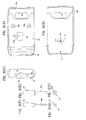
Fig. 9(A) is a front view of the first and second covers.Fig. 9(B) is a bottom view of the first and second covers.Fig. 9(C) is a left side view of the first and second covers.Fig. 9(D) is a front view of a latch member rotating tool for rotating the latch member.Fig. 9(E) is a bottom view of the latch member rotating tool. Fig. 9(F) is a front view of a slider moving tool for moving the slider. Fig. 9(G) is a bottom view of the slider moving tool. Note that inFigs. 9(A) to 9(C) , the first cover is mated with the second cover. - As illustrated in
Figs. 9(A) to 9(C) , each of thefirst cover 19 and thesecond cover 20 are formed of a synthetic resin. Thefirst cover 19 has alatch releasing hole 19a for unlatching the seatbelt locking buckle 5 from the seatbelt locking tongue 6. In such a case, thelatch releasing hole 19a is disposed at a position facing thelatch releasing groove 13e of thebuckle latch member 13. Therefore, thelatch releasing groove 13e of thebuckle latch member 13 is visible through thelatch releasing hole 19a. When thebuckle latch member 13 is rotatable, agroove engagement portion 23a of a latchmember rotating tool 23 illustrated inFigs. 9(D) and 9(E) is engaged with thelatch releasing groove 13e through thelatch releasing hole 19a. Thereafter, the latchmember rotating tool 23 is rotated. Thus, thebuckle latch member 13 is rotated. - In addition, as illustrated in
Fig. 9(C) , the left end of thefirst cover 19 illustrated inFigs. 9(A) and 9(B) has a seat belt lockingtongue insertion port 19b formed therein. The seat belt lockingtongue insertion port 19b has a substantially rectangular shape and allows thetongue latch member 6b of the seatbelt locking tongue 6 to be inserted into the seatbelt locking buckle 5. In addition, a tongue-latch-portion guide portion 19c is formed in the middle of one side edge of the seat belt lockingtongue insertion port 19b that extends in the length direction. When thetongue latch member 6b of the seatbelt locking tongue 6 is inserted into the seatbelt locking buckle 5, the tongue-latch-portion guide portion 19c leads thetongue latch member 6b. Furthermore, a tongue insertion prevention portionpassage permitting groove 19d (corresponding to a tongue latch member wrong insertion prevention portion insertion permitting portion according to the present invention) is formed in the middle of the other side edge of the seat belt lockingtongue insertion port 19b that extends in the length direction. The tongue insertion prevention portionpassage permitting groove 19d has a circular arc shape in lateral cross section. When thetongue latch member 6b of the seatbelt locking tongue 6 is inserted into the seatbelt locking buckle 5 under a normal condition, the tongue insertion prevention portionpassage permitting groove 19d allows a tongueinsertion regulation portion 6g provided in thetongue latch member 6b (illustrated below inFigs. 10(A) to 10(C) and corresponding to the tongue latch member wrong insertion prevention portion of the present invention) to pass through the seat belt lockingtongue insertion port 19b. Still furthermore, a thin-wall portion 19e is formed at the end of thefirst cover 19 opposite to the end having the seat belt lockingtongue insertion port 19b. The thin-wall portion 19e has a seat belt through-hole 19f formed therein. In addition, as illustrated inFig. 2 ,female screw portions 19g and 19h are provided inside of thefirst cover 19. Thefemale screw portions 19g and 19h allow the assembling screws 21 to be threadably mounted thereon. - In contrast, as illustrated in
Fig. 9(A) , thesecond cover 20 has an elongated linearslider movement hole 20a formed therein. Theslider movement hole 20a allows theslider 16 located at a position at which thebuckle latch member 13 is latched and held to move. In such a case, when the seatbelt locking tongue 6 and the seatbelt locking buckle 5 are latched together, the end of theslider 16 is visible through theslider movement hole 20a. As illustrated in Figs. 9(F) and 9(G), aslider pressing portion 24a of aslider moving tool 24 is brought into contact with an end of theslider 16 through theslider movement hole 20a. Thereafter, by urging theslider moving tool 24 against theslider 16, theslider 16 can be moved toward a non-operating position. - The
second cover 20 further has an assemblingscrew mounting holes 20b formed therein. The assemblingscrew mounting holes 20b allow the assembling screws 21 to pass therethrough. Still furthermore, thesecond cover 20 has a thin-wall portion 20c at one end thereof. The thin-wall portion 20c has a seat belt through-hole 20d formed therein. In such a case, when the seatbelt locking buckle 5 is assembled, the seat belt through-hole 11d of thefirst base 11, the seat belt through-hole 12a of thesecond base 12, the seat belt through-hole 19f of thefirst cover 19, and the seat belt through-hole 20d of thesecond cover 20 are at least partially aligned with one another. When, as indicated by an alternate long and two short dashes line inFig. 5(A) , the seat belt 4 is inserted into the seat belt through-holes first cover 19 andsecond cover 20 due to the presence of the thin-wall portion 19e of thefirst cover 19 and the thin-wall portion 20c of thesecond cover 20. Thus, a connection portion of the seat belt 4 and the seatbelt locking buckle 5 is compact and not bulky. As a result, the seatbelt locking buckle 5 connected to the seat belt 4 can be easily handled. -
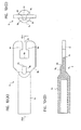
Fig. 10(A) is a plan view of the seat belt locking tongue.Fig. 10(B) is a cross-sectional view taken along a line XB - XB ofFig. 10(A). Fig. 10(C) is a right side view of the seat belt locking tongue.
As illustrated inFigs. 10(A) to 10(C) , the seatbelt locking tongue 6 is formed of a metal material. The seatbelt locking tongue 6 includes a fixingportion 6a to be fixed to a pretensioner fixed to the vehicle body and atongue latch member 6b. The fixingportion 6a has a bottomed cylindrical shape. In contrast, thetongue latch member 6b is formed so as to be integrated into the fixingportion 6a in a substantially rectangular plate shape. Thetongue latch member 6b can be partially inserted into the space S formed between thefirst base 11 and thesecond base 12 through the seat belt lockingtongue insertion port 19b of thefirst cover 19. - The
tongue latch member 6b has a substantiallysquare hole 6c formed in the substantially middle thereof and anopen passage 6d that allows thehole 6c to communicate with the outside of thetongue latch member 6b. The length of a side of thesquare hole 6c is slightly larger than the diameter of the cylindrical portion of thebuckle latch portion 13a. In addition, the width of theopen passage 6d is slightly larger than the width of the seat belt locking tonguepassage enabling groove 13d and is slightly smaller than the diameter of the cylindrical portion of thebuckle latch portion 13a. Accordingly, the seat belt locking tonguepassage enabling groove 13d of thebuckle latch portion 13a can pass through theopen passage 6d. However, the cylindrical portion of thebuckle latch portion 13a cannot pass through theopen passage 6d. That is, a portion of thetongue latch member 6b having theopen passage 6d formed therein serves as a firsttongue latch portion 6e and a secondtongue latch portion 6f that extend in a direction perpendicular or substantially perpendicular to the direction in which the seatbelt locking tongue 6 is inserted and that can be engaged with the cylindrical portion of thebuckle latch portion 13a. - In addition, the
tongue latch member 6b has a tongueinsertion regulation portion 6g formed therein. The tongueinsertion regulation portion 6g regulates the length of a portion of thetongue latch member 6b that is inserted into the seatbelt locking buckle 5 to a predetermined length. The predetermined length used to regulate the length of a portion of thetongue latch member 6b that is inserted is set to a value that causes thetongue latch member 6b of the seatbelt locking tongue 6 to be stably latched by thebuckle latch portion 13a of thebuckle latch member 13. In this manner, an excessive length of a portion of thetongue latch member 6b that is inserted into the seatbelt locking buckle 5 is avoid. In addition, through the regulation of the length of the portion that is inserted, an operator can easily and stably perform the latch operation of the seatbelt locking buckle 5 with the seatbelt locking tongue 6. The tongueinsertion regulation portion 6g is formed in a circular arc shape in lateral cross section and extends in a direction in which the seatbelt locking tongue 6 is inserted into the seatbelt locking buckle 5. In such a case, the circular arc shape of the tongueinsertion regulation portion 6g is slightly smaller than the tongue insertion prevention portionpassage permitting groove 19d and, therefore, the tongueinsertion regulation portion 6g can pass through the tongue insertion prevention portionpassage permitting groove 19d. - Note that the seat
belt locking buckle 5 of the present embodiment allows an operator to visually check whether the seatbelt locking buckle 5 is properly latched by the seatbelt locking tongue 6. -
Fig. 11 illustrates visual check as to whether the seat belt locking buckle is properly latched by the seat belt locking tongue.Fig. 11(A) is a perspective view of the seat belt locking buckle that is not latched by the seat belt locking tongue.Fig. 11(B) is a cross-sectional view taken along a line XIB - XIB ofFig. 11(A). Fig. 11(C) is a perspective view of the seat belt locking buckle that is properly latched by the seat belt locking tongue.Fig. 11(D) is a cross-sectional view taken along a line XID - XID ofFig. 11(C) . - As illustrated in
Figs. 11(A) to 11(D) , thesecond cover 20 has a latch detection shaft through-hole 20e formed therein. The latch detection shaft through-hole 20e allows thelatch detection shaft 16c of theslider 16 that has passed through the latch detection shaft through-hole 11s of thefirst side wall 11b of thefirst cover 19 to pass therethrough in a slidable manner. - In addition, as illustrated in
Figs. 11(A) and 11(B) , when the seatbelt locking buckle 5 is not latched by the seatbelt locking tongue 6, thelatch detection shaft 16c passes through the latch detection shaft through-hole 20e and protrudes to the outside of thesecond cover 20. Accordingly, the operator can recognize that the seatbelt locking buckle 5 is not latched by the seatbelt locking tongue 6 if the operator views thelatch detection shaft 16c protruding from thesecond cover 20. In addition, as illustrated inFigs. 11(C) and 11(D) , if the seatbelt locking buckle 5 is properly latched by the seatbelt locking tongue 6, thelatch detection shaft 16c is placed inside thesecond cover 20 and does not protrude to the outside of thesecond cover 20. Accordingly, the operator can recognize that the seatbelt locking buckle 5 is properly latched by the seatbelt locking tongue 6 if the operator does not see thelatch detection shaft 16c that is placed inside thesecond cover 20. - The operation performed by the seat
belt locking buckle 5 and the seat belt apparatus 1 having the above-described structure according to the present embodiment is described next.
As illustrated inFig. 12 , when the seatbelt locking buckle 5 is not latched by the seatbelt locking tongue 6, theejector 14 is located at the operating position (the leftmost position inFig. 12 ). At the operating position of theejector 14, the latch memberrotation prevention portion 14g is in contact with the side surface of the firstlatch guide portion 13b. Thus, the length direction of the firstlatch guide portion 13b is set to a direction in which the seatbelt locking tongue 6 is inserted. Accordingly, the seat belt locking tonguepassage enabling groove 13d is also oriented to that direction. In addition, at the operating position of theejector 14, the controlledsurface 16b of theslider 16 is in contact with theslider control portion 14f of theejector 14. Thus, theslider 16 is set at a non-operating position illustrated inFig. 12 (the lowermost position inFig. 12 ). Note that the biasing forces of theejector spring 15 and theslider spring 18 and the inclination angles of theslider control portion 14f and the controlledsurface 16b are determined so that theejector 14 can set theslider 16 at the non-operating position. - At the non-operating position of the
slider 16, the latchmember pressing portion 16f of theslider 16 is not in contact with the firstlatch guide portion 13b and is slightly separated from the firstlatch guide portion 13b. Accordingly, the biasing force of theslider spring 18 is not exerted on the firstlatch guide portion 13b. Consequently, thebuckle latch member 13 is located at the non-latch position illustrated inFig. 12 . In addition, as illustrated inFigs. 11(A) and 11(B) andFig. 12 , at the non-operating position of theslider 16, thelatch detection shaft 16c protrudes from thesecond cover 20. Thus, the operator can see thelatch detection shaft 16c that protrudes and, therefore, can recognize that the seatbelt locking tongue 6 is latched by the seatbelt locking buckle 5. - As illustrated in
Fig. 5(B) , in order for the seatbelt locking buckle 5 to be latched by the seatbelt locking tongue 6, the seatbelt locking buckle 5 is fitted into thetongue latch member 6b of the seatbelt locking tongue 6 through the seat belt lockingtongue insertion port 19b with a predetermined pressing force. At that time, the seatbelt locking buckle 5 is fitted into thetongue latch member 6b under a normal condition, the tongue insertion prevention portionpassage permitting groove 19d of the seat belt lockingtongue insertion port 19b of thefirst cover 19 passes through the tongueinsertion regulation portion 6g of the seatbelt locking tongue 6. Accordingly, the seatbelt locking buckle 5 is smoothly fitted into thetongue latch member 6b under a normal condition. In addition, since the tongue-latch-portion guide portion 19c passes through theopen passage 6d of thetongue latch member 6b, the seatbelt locking buckle 5 is more smoothly fitted. In this manner, thetongue latch member 6b of the seatbelt locking tongue 6 can be more deeply inserted into the seatbelt locking buckle 5. - In contrast, if the seat
belt locking buckle 5 is turned over, that is, if the tongue insertion prevention portionpassage permitting groove 19d of the seat belt lockingtongue insertion port 19b of thefirst cover 19 is accidentally placed on the opposite side on which the tongue insertion prevention portionpassage permitting groove 19d does not face the tongueinsertion regulation portion 6g of the seatbelt locking tongue 6, passes through the seat belt lockingtongue insertion port 19b, and is fitted into thetongue latch member 6b, the seat belt lockingtongue insertion port 19b of the seatbelt locking buckle 5 is brought into contact with atop end 6h of the tongueinsertion regulation portion 6g of thetongue latch member 6b, since the tongue insertion prevention portionpassage permitting groove 19d is not present on the side of the tongueinsertion regulation portion 6g. Accordingly, the seatbelt locking buckle 5 cannot be further deeply fitted into thetongue latch member 6b. That is, thetongue latch member 6b of the seatbelt locking tongue 6 cannot be inserted into the latch position in the seatbelt locking buckle 5. In this manner, the seatbelt locking buckle 5 is not latched by the seatbelt locking tongue 6 by mistake. As a result, a twisted seat belt is not attached to the vehicle body. - When the
tongue latch member 6b of the seatbelt locking tongue 6 is inserted into the seatbelt locking buckle 5, the seat belt locking tonguepassage enabling groove 13d of thebuckle latch portion 13a is located inside of theopen passage 6d of the seatbelt locking tongue 6. Accordingly, thetongue latch member 6b is inserted into the seatbelt locking buckle 5 while passing through thebuckle latch portion 13a. - If the
tongue latch member 6b of the seatbelt locking tongue 6 is further inserted into the seatbelt locking buckle 5, the top end of thetongue latch member 6b is brought into contact with the seat belt fixingcontact surface 14e of theejector 14 and pushes theejector 14. Thus, as illustrated inFig. 13 , theejector 14 moves in a direction in which thetongue latch member 6b moves (in the right direction inFig. 13 ) together with thetongue latch member 6b. In this manner, the latch memberrotation prevention portion 14g also moves in the same direction. At that time, the latch memberrotation prevention portion 14g is still in contact with the side surface of the firstlatch guide portion 13b. - Since the
ejector 14 moves, theslider control portion 14f of theejector 14 is separated from the controlledsurface 16b of theslider 16. Thus, as illustrated inFig. 13 , theslider 16 moves upward due to the biasing force of theslider spring 18, and the latchmember pressing portion 16f of theslider 16 is brought into contact with an end portion of the side surface of the firstlatch guide portion 13b opposite the side surface with which the latch memberrotation prevention portion 14g is brought into contact. In this manner, the biasing force of theslider spring 18 is exerted on the firstlatch guide portion 13b. However, since the latch memberrotation prevention portion 14g is in contact with the side surface of the firstlatch guide portion 13b, the firstlatch guide portion 13b does not rotate even when the biasing force of theslider spring 18 is exerted on the firstlatch guide portion 13b. Accordingly, thebuckle latch member 13 maintains its orientation in the non-latch state of the seatbelt locking buckle 5, as illustrated inFig. 12 . - If the
tongue latch member 6b is further deeply inserted into the seatbelt locking buckle 5, theejector 14 moves in the same direction as thetongue latch member 6b. Accordingly, as illustrated inFig. 14(A) , the latch memberrotation prevention portion 14g of theejector 14 is about to be separated from the side surface of the firstlatch guide portion 13b. That is, thebuckle latch member 13 is about to start a latch operation. At that time, as illustrated inFig. 14(B) , the entirety of thebuckle latch portion 13a of thebuckle latch member 13 is located in thehole 6c of thetongue latch member 6b. In addition, the length direction of the seat belt locking tonguepassage enabling groove 13d of thebuckle latch portion 13a is set to a direction that is the same or substantially the same as the direction in which thetongue latch member 6b is inserted. - Thereafter, if the
tongue latch member 6b is further deeply inserted into the seatbelt locking buckle 5, the latch memberrotation prevention portion 14g is separated from the side surface of the firstlatch guide portion 13b. Accordingly, as illustrated inFig. 14(A) , the firstlatch guide portion 13b is rotated in a counterclockwise direction due to the biasing force of theslider spring 18. That is, thebuckle latch member 13 is rotated, in the same direction, about an axis that is perpendicular or substantially perpendicular to a plane of the motion of thetongue latch member 6b. At that time, since thebuckle latch member 13 is supported by thefirst base 11 and thesecond base 12 so as to be only rotatable and, therefore, thebuckle latch member 13 smoothly and efficiently rotates without any linear motion. - As illustrated in
Fig. 15(A) , if thetongue latch member 6b is further deeply inserted into the seatbelt locking buckle 5, thetop end 6h of the tongueinsertion regulation portion 6g of the seatbelt locking tongue 6 is brought into contact with aside end 12p (the left end inFig. 15(A) ) of the seat belt fixing tongue insertion port of thesecond base 12. Accordingly, insertion of thetongue latch member 6b into the seatbelt locking buckle 5 is stopped, and thetongue latch member 6b is located at a full stroke position of the seatbelt locking tongue 6. In addition, at the full stroke position of the seatbelt locking tongue 6, movement of theslider 16 is stopped by a stopper (not illustrated), and theslider 16 is located at an operating position at which theslider 16 maximally moved, as illustrated inFig. 15(A) . - As illustrated in
Fig. 15(A) , at the operating position of theslider 16, the firstlatch guide portion 13b of thebuckle latch member 13 rotates up to a position at which the firstlatch guide portion 13b is in contact with the latch memberrotation prevention portion 16g of theslider 16 due to a force of inertia of rotation, and the firstlatch guide portion 13b is held at the rotational position. At the rotational position, the length direction of the firstlatch guide portion 13b is slightly inclined with respect to a direction in which theslider 16 moves. Accordingly, as illustrated inFig. 15(B) , like the firstlatch guide portion 13b, the seat belt locking tonguepassage enabling groove 13d is slightly inclined with respect to the direction in which theslider 16 moves. - If a pressing force exerted on the seat
belt locking buckle 5 for latching the seatbelt locking tongue 6 is released after the seatbelt locking tongue 6 makes a full stroke, theejector 14 urges thetongue latch member 6b of the seatbelt locking tongue 6 in a direction in which thetongue latch member 6b is ejected from the seatbelt locking buckle 5 due to the biasing force of theejector spring 15. Thus, thetongue latch member 6b is moved in that direction. At that time, since, as described above, the seat belt locking tonguepassage enabling groove 13d is inclined, the firsttongue latch portion 6e, which is one of two tongue latch portions of thetongue latch member 6b, is brought into contact with the side surface of the seat belt locking tonguepassage enabling groove 13d due to the movement of thetongue latch member 6b. In this manner, the firsttongue latch portion 6e pushes the seat belt locking tonguepassage enabling groove 13d and rotates thebuckle latch member 13 in a clockwise direction, as illustrated inFigs. 15(A) and 15(B) . - As illustrated in
Fig. 16(B) , due to the rotation of thebuckle latch member 13, the side surface of the seat belt locking tonguepassage enabling groove 13d is also brought into contact with the secondtongue latch portion 6f, which is the other of two tongue latch portions of thetongue latch member 6b. Thus, rotation of thebuckle latch member 13 is stopped, and the side surface of the seat belt locking tonguepassage enabling groove 13d is brought into contact with both the firsttongue latch portion 6e and the secondtongue latch portion 6f. That is, thebuckle latch member 13 is located at the latch position. In such a state of the seat belt locking tonguepassage enabling groove 13d, the side surface of the seat belt locking tonguepassage enabling groove 13d is parallel or substantially parallel to the direction in which theslider 16 moves. Accordingly, as illustrated inFig. 16(A) , the length direction of the firstlatch guide portion 13b is also parallel to or substantially parallel to the direction in which theslider 16 moves. Since the length direction of the firstlatch guide portion 13b is also parallel to or substantially parallel to the direction in which theslider 16 moves, thefirst base 11 and thesecond base 12 assembled together is sandwiched by the firstlatch guide portion 13b and the secondlatch guide portion 13c. In addition, theslider 16 is significantly close to the firstlatch guide portion 13b. Thus, when thebuckle latch member 13 is located at the latch position illustrated inFig. 16(A) and if thebuckle latch member 13 is about to rotate, the firstlatch guide portion 13b is brought into contact with theslider 16. Accordingly, theslider 16 prevents (locks) rotation of thebuckle latch member 13 from the latch position. In addition, the center of gravity G of thebuckle latch member 13 is significantly close to the rotation axis α of thebuckle latch member 13. Accordingly, if an external force is exerted on thebuckle latch member 13 toward the non-latch position, the rotation torque of thebuckle latch member 13 caused by the external force is small. Consequently, even when an external force is exerted on thebuckle latch member 13 toward the non-latch position, rotation of thebuckle latch member 13 toward the non-latch position is effectively prevented. Accordingly, when thebuckle latch member 13 is located at the latch position, accidental rotation can be prevented. - In this manner, as illustrated in
Fig. 5(C) andFigs. 16(A) and 16(B) , the firsttongue latch portion 6e and the secondtongue latch portion 6f are latched by thebuckle latch portion 13a. Thus, the seatbelt locking buckle 5 is properly latched by the seatbelt locking tongue 6. Accordingly, the top end of the seat belt 4 is secured to the vehicle body. As illustrated inFigs. 11(C) and 11(D) andFig. 16(A) , when the seatbelt locking buckle 5 is properly latched by the seatbelt locking tongue 6, thelatch detection shaft 16c is disposed inside of thesecond cover 20 and does not protrude from thesecond cover 20. Accordingly, the operator does not see thelatch detection shaft 16c and, thus, the operator can recognize that the seatbelt locking tongue 6 is properly latched by the seatbelt locking buckle 5. - When the seat
belt locking buckle 5 is properly latched by the seatbelt locking tongue 6 and if, in the event of emergency, a tension force that is larger than that in a normal case is exerted on the seat belt 4, each of the seatbelt locking buckle 5 and the seatbelt locking tongue 6 is pulled in a direction in which the seatbelt locking buckle 5 is unlatched from the seatbelt locking tongue 6. The end portions of thefirst base 11 and thesecond base 12 into which thetongue latch member 6b is inserted receives a force that attempts to spread the end portions apart. However, since the first tofourth engagement portion second base 12 are firmly fitted into and engaged with the corresponding first to fourthengagement support groove first base 11 and thesecond base 12 is prevented even when a force to spread thefirst base 11 and thesecond base 12 apart is exerted thereon. In particular, since thefirst base 11 and thesecond base 12 are sandwiched by the firstlatch guide portion 13b and the secondlatch guide portion 13c, spread of thefirst base 11 and thesecond base 12 can be effectively prevented. That is, according to the present embodiment, thebuckle latch member 13 reinforces the strength of thefirst base 11 and thesecond base 12. - In order to unlatch the seat
belt locking buckle 5 and the seatbelt locking tongue 6 latched together, theslider 16 is moved to the non-operating position by theslider pressing portion 24a of theslider moving tool 24, as described above. Thus, thebuckle latch member 13 becomes rotatable. Thereafter, thebuckle latch member 13 is rotated by the latchmember rotating tool 23. Thus, as illustrated inFig. 14(B) , the seat belt locking tonguepassage enabling groove 13d is disposed along a direction that is the same as the direction in which thetongue latch member 6b illustrated inFig. 14(B) is ejected. Thereafter, thetongue latch member 6b is ejected from the seatbelt locking buckle 5 by theejector 14, and the seatbelt locking buckle 5 is unlatched from the seatbelt locking tongue 6. As described above, in order to unlatch the seatbelt locking buckle 5 from the seatbelt locking tongue 6, an operation for moving theslider 16 from both sides of the seatbelt locking buckle 5 using theslider moving tool 24 and the latchmember rotating tool 23 for unlatching and an operation for rotating thebuckle latch member 13 need to be performed at the same time. In this manner, it is difficult for an ordinary user to easily unlatch the seatbelt locking buckle 5 from the seatbelt locking tongue 6 and, thus, the seatbelt locking buckle 5 is unlatched from the seatbelt locking tongue 6 by only a technician, such as a customer engineer. - According to the seat
belt locking buckle 5 of the present embodiment, thebuckle latch member 13 moves along a plane that is parallel or substantially parallel to a plane extending in a direction in which thetongue latch member 6b of the seatbelt locking tongue 6 is inserted and ejected (that is, the direction in which thetongue latch member 6b moves). In addition, rotation of thebuckle latch member 13 is controlled by theslider 16 that serves as a rotation control member. Accordingly, unlike existing seat belt locking buckles, the seatbelt locking buckle 5 does not include a torsion spring that is disposed along the thickness direction of the seatbelt locking buckle 5 and that urges thebuckle latch member 13 in the rotational direction and, therefore, the thickness of the seatbelt locking buckle 5 can be reduced. In addition, since thetongue latch member 6b is latched by thebuckle latch member 13 having a substantially cylindrical shape, thebuckle latch member 13 and thetongue latch member 6b can be stably and firmly latched together. - Furthermore, when the
tongue latch member 6b is not inserted into the seatbelt locking buckle 5, theslider 16 is separated from thebuckle latch member 13 and, thus, theslider 16 does not push thebuckle latch member 13. In this manner, when thebuckle latch member 13 is assembled, thebuckle latch member 13 is not pushed by theslider 16. Consequently, thebuckle latch member 13 can be easily assembled. - Still furthermore, when the
tongue latch member 6b is inserted into the seatbelt locking buckle 5, the assembledfirst base 11 andsecond base 12 are sandwiched by the firstlatch guide portion 13b and the secondlatch guide portion 13c of thebuckle latch member 13. Thus, even when, in the event of emergency, a tensional force that is greater than in a normal case is exerted on the seat belt 4 to spread the assembledfirst base 11 andsecond base 12 from each other, the firstlatch guide portion 13b and the secondlatch guide portion 13c can effectively prevent the spread of thefirst base 11 and thesecond base 12. That is, the strength of the assembledfirst base 11 andsecond base 12 can be reinforced by thebuckle latch member 13. - Yet still furthermore, the
latch detection shaft 16c is provided. When the seatbelt locking tongue 6 is not latched by the seatbelt locking buckle 5, thelatch detection shaft 16c protrudes from thefirst cover 19 to the outside of thefirst cover 19. In contrast, when the seatbelt locking tongue 6 is latched by the seatbelt locking buckle 5, thelatch detection shaft 16c is retracted into thefirst cover 19. Thus, by visually recognizing whether thefirst cover 19 protrudes to the outside of thefirst cover 19, the operator can determine whether the seatbelt locking tongue 6 and the seatbelt locking buckle 5 are latched together. In particular, by providing thelatch detection shaft 16c in theslider 16, the structure for detecting a latch condition can be simplified. - In addition, the latch member
rotation prevention portion 14g is formed from theejector 14 that urges thetongue latch member 6b in the direction in which thetongue latch member 6b is ejected from the seatbelt locking buckle 5. Accordingly, the structure for latching the seatbelt locking buckle 5 can be simplified. - In addition, according to the present embodiment, the seat belt apparatus 1 includes the seat
belt locking buckle 5 of the present embodiment capable of stably and firmly latching the seatbelt locking tongue 6 and reducing the thickness of the seat belt apparatus 1. Thus, an occupant can be effectively restrained by using the seat belt 4. Furthermore, since a space occupied by the seat belt apparatus 1 is reduced, the seat belt apparatus 1 does not interfere with a motion of the occupant in a vehicle compartment. - In addition, the tongue
insertion regulation portion 6g is provided. By using the tongueinsertion regulation portion 6g, the length of a portion of thetongue latch member 6b inserted into the seatbelt locking buckle 5 can be controlled to a predetermined length. Accordingly, the seatbelt locking buckle 5 and the seatbelt locking tongue 6 can be easily and stably latched together. - Furthermore, the tongue
insertion regulation portion 6g is configured as a tongue latch member wrong insertion preventing portion. The tongue latch member wrong insertion preventing portion prevents thetongue latch member 6b from being accidentally turned over and inserted. In this manner, a twisted seat belt 4 cannot be buckled and, therefore, the occupant can be more reliably restrained by the seat belt 4. In addition, since the tongue latch member wrong insertion preventing portion is formed from the tongueinsertion regulation portion 6g, the structure of the tongue latch member wrong insertion preventing portion can be simplified. - While the above-described embodiment has been described with reference to the seat
belt locking buckle 5 provided at the top end of the seat belt 4 and the seatbelt locking tongue 6 mounted on the vehicle body via thepretensioner 7, the seatbelt locking buckle 5 may be mounted on the vehicle body via thepretensioner 7, and the seatbelt locking tongue 6 may be provided at the top end of the seat belt 4. In addition, when each of the seatbelt locking buckle 5 and the seatbelt locking tongue 6 is mounted on the vehicle body, the seatbelt locking buckle 5 or the seat belt 4 can be directly mounted on the vehicle body without using thepretensioner 7. That is, various design modifications can be made in the seat belt locking buckle of the present invention within the scope of appended Claims. - According to the present invention, the seat belt locking buckle and the seat belt apparatus can be suitably applied as a seat belt locking buckle for securing a top end of a seat belt that restrains an occupant in the event of emergency, such as collision, in which deceleration that is greater than that in a normal case is applied to the vehicle and a seat belt apparatus including the seat belt locking buckle.
-
- 1: seat belt apparatus
- 3: seat belt retractor
- 4: seat belt
- 5: seat belt locking buckle
- 6: seat belt locking tongue
- 6b: tongue latch member
- 6c: hole
- 6d: open passage
- 6e: first tongue latch portion
- 6f: second tongue latch portion
- 6g: tongue insertion regulation portion
- 7: pretensioner
- 9: tongue
- 10: buckle
- 11: first base
- 12: second base
- 13: buckle latch member
- 13a: buckle latch portion
- 13b: first latch guide portion
- 13c: second latch guide portion
- 13d: seat belt locking tongue passage enabling groove
- 13e: latch releasing groove
- 14: ejector
- 14b: latch member/slider control portion
- 14f: slider control portion
- 14g: latch member rotation prevention portion
- 16: slider
- 16b: controlled surface
- 16c: latch detection shaft
- 16f: latch member pressing portion
- 16g: latch member rotation prevention portion
- 19: first cover
- 19a: latch releasing hole
- 19b: seat belt locking tongue insertion port
- 19d: tongue insertion prevention portion passage permitting groove
- 19e: thin-wall portion
- 20: second cover
- 20a: slider movement hole
- 20e: latch detection shaft through-hole
- 23: latch member rotating tool
- 24: slider moving tool
Claims (13)
- A seat belt locking buckle (5) directly or indirectly mounted on one of a seat belt (4) and a vehicle body, the seat belt locking buckle (5) securing a top end of the seat belt (4) to the vehicle body by latching a seat belt locking tongue (6) mounted directly or indirectly on the other of the seat belt (4) and the vehicle body, the seat belt locking buckle (5) comprising:a seat belt locking tongue insertion port (19b) that allows a tongue latch member (6b) of the seat belt locking tongue (6) to be inserted into the seat belt locking buckle (5) ;a buckle latch member (13) having a substantially solid cylindrical shape, the buckle latch member (13) being disposed so as to be rotatable about an axis extending in a direction perpendicular or substantially perpendicular to a plane of the motion of the tongue latch member (6b) inserted into the seat belt locking buckle (5) through the seat belt locking tongue insertion port (19b) at least between a non-latch position at which the tongue latch member (6b) is not latchable by the buckle latch member (13) and a latch position at which the tongue latch member (6b) is latchable by the buckle latch member (13);a latch member rotation control member (14) that disables rotation of the buckle latch member (13) and holds the buckle latch member (13) at the non-latch position when the tongue latch member (6b) is not inserted into the seat belt locking buckle (5) and that enables rotation of the buckle latch member (13) when moved by the tongue latch member (6b) inserted into the seat belt locking buckle (5) along a plane parallel or substantially parallel to the plane of the motion of the tongue latch member (6b); anda latch-member operating member (16) that moves along a plane parallel or substantially parallel to the plane of the motion of the tongue latch member (6b) when the buckle latch member (13) is rotatable and pushes the buckle latch member (13) to rotate the buckle latch member (13) from the non-latch position to the latch position.
- The seat belt locking buckle (5) according to Claim 1,
wherein the latch-member operating member is separated from the buckle latch member (13) and does not push the buckle latch member (13) when the tongue latch member (6b) is not inserted into the seat belt locking buckle (5), and
wherein the latch-member operating member (16) is in contact with the buckle latch member (13) and pushes the buckle latch member (13) when the latch member rotation control member (14) is moved by the tongue latch member (6b) inserted into the seat belt locking buckle (5). - The seat belt locking buckle (5) according to Claim 1 or Claim 2, further comprising:a first base (11) and a second base (12),wherein the first base (11) and the second base (12) are assembled together so that a space that allows the tongue latch member (6b) inserted through the seat belt locking tongue insertion port (19b) to be inserted thereinto is formed between the first base (11) and the second base (12), andwherein the buckle latch member (13) includes a first latch guide portion (13b) and a second latch guide portion (13c) by which the assembled first base (11) and second base (12) are sandwiched when the tongue latch member (6b) and the buckle latch member (13) are latched together.
- The seat belt locking buckle (5) according to Claim 3, wherein the latch-member operating member (16) rotates the buckle latch member (13) from the non-latch position to the latch position by coming into contact with the first latch guide portion (13b) and pushing the first latch guide portion (13b).
- The seat belt locking buckle (5) according to Claim 4,
wherein the latch member rotation control member (14) does not allow the latch-member operating member (16) to be in contact with the first latch guide portion (13b) when the tongue latch member (6b) is not inserted into the seat belt locking buckle (5), and
wherein the latch member rotation control member (14) causes the latch-member operating member (16) to be in contact with the first latch guide portion (13b) when the latch member rotation control member (14) is moved by the tongue latch member (6b). - The seat belt locking buckle (5) according to any one of Claims 3 to 4, further comprising:a cover (19) that contains at least the buckle latch member (13), the latch member rotation control member (14), the latch-member operating member (16), the first base (11), and the second base (12), the cover (19) having the seat belt locking tongue insertion port (19b) formed therein; anda latch detection unit (16c) that protrudes from the cover (19) to the outside of the cover (19) when the seat belt locking tongue (6) is not latched by the seat belt locking buckle (5) and that retracts into the cover (19) when the seat belt locking tongue (6) is latched by the seat belt locking buckle (5).
- The seat belt locking buckle (5) according to Claim 6, wherein the latch detection unit (16c) is disposed in the latch-member operating member (16).
- The seat belt locking buckle (5) according to any one of Claims 1 to 7, further comprising:an ejector (14) that urges the tongue latch member (6b) inserted into the seat belt locking buckle (5) in a direction in which the tongue latch member (6b) is ejected from the seat belt locking buckle (5),wherein the ejector (14) serves as the latch member rotation control member.
- A seat belt apparatus (1) comprising:a seat belt (4) capable of restraining a vehicle occupant;a seat belt retractor (3) that retracts the seat belt (4) therein;a tongue (9) slidably supported by the seat belt (4);a buckle (10) that allows the tongue (9) to be inserted thereinto and engaged therewith;a seat belt locking buckle (5) directly or indirectly mounted on one of the seat belt (4) and a vehicle body; anda seat belt locking tongue (6) directly or indirectly mounted on the other of the seat belt (4) and the vehicle body, the seat belt locking tongue (6) being latchable by the seat belt locking buckle (5),wherein the seat belt locking buckle (5) is the seat belt locking buckle (5) according to any one of Claims 1 to 8.
- The seat belt apparatus (1) according to Claim 9, wherein the tongue latch member (6b) includes a tongue insertion regulation portion (6g) that regulates the length of a portion of the tongue latch member (6b) that is inserted into the seat belt locking buckle (5) to a predetermined length.
- The seat belt apparatus (1) according to Claim 10, wherein the tongue insertion regulation portion (6g) further functions as a tongue latch member wrong insertion preventing portion (13d) that prevents the tongue latch member (6b) from being accidentally turned over and inserted.
- The seat belt apparatus (1) according to Claim 9, wherein the tongue latch member (6b) includes a tongue latch member wrong insertion preventing portion (13d) that prevents the tongue latch member (6b) from being accidentally turned over and inserted.
- The seat belt apparatus (1) according to Claim 11 or 12, wherein the seat belt locking buckle (5) includes a tongue latch member wrong insertion prevention portion insertion permitting portion (13d) formed in the seat belt locking tongue insertion port (19b), and the tongue latch member wrong insertion prevention portion insertion permitting portion (13d) allows the tongue latch member wrong insertion preventing portion (13d) to pass therethrough.
Applications Claiming Priority (1)
| Application Number | Priority Date | Filing Date | Title |
|---|---|---|---|
| JP2011273280A JP5722756B2 (en) | 2011-12-14 | 2011-12-14 | Seat belt fixing buckle and seat belt device provided with the same |
Publications (1)
| Publication Number | Publication Date |
|---|---|
| EP2604137A1 true EP2604137A1 (en) | 2013-06-19 |
Family
ID=47504565
Family Applications (1)
| Application Number | Title | Priority Date | Filing Date |
|---|---|---|---|
| EP12008202.9A Withdrawn EP2604137A1 (en) | 2011-12-14 | 2012-12-07 | Seat belt locking buckle and seat belt apparatus including seat belt locking buckle |
Country Status (3)
| Country | Link |
|---|---|
| US (1) | US8746743B2 (en) |
| EP (1) | EP2604137A1 (en) |
| JP (1) | JP5722756B2 (en) |
Families Citing this family (4)
| Publication number | Priority date | Publication date | Assignee | Title |
|---|---|---|---|---|
| EP4151261A1 (en) | 2015-03-31 | 2023-03-22 | Fisher & Paykel Healthcare Limited | A user interface and system for supplying gases to an airway |
| CN114569856A (en) | 2016-08-11 | 2022-06-03 | 费雪派克医疗保健有限公司 | Collapsible catheter, patient interface and headgear connector |
| CN108791173A (en) * | 2018-08-01 | 2018-11-13 | 沈阳金杯锦恒汽车安全系统有限公司 | Belt buckle, safety belt with error-disable function and automobile |
| CN113941159B (en) * | 2020-07-17 | 2023-10-31 | 智崴资讯科技股份有限公司 | Fastener device |
Citations (4)
| Publication number | Priority date | Publication date | Assignee | Title |
|---|---|---|---|---|
| US3555632A (en) * | 1967-10-06 | 1971-01-19 | Stig Martin Lindblad | Safety belt clasp |
| US20030071453A1 (en) | 2001-10-16 | 2003-04-17 | Trw Occupant Restraint Systems Gmbh & Co. Kg | Tensioner-proof closure for a safety belt |
| WO2006132129A1 (en) * | 2005-06-10 | 2006-12-14 | Autoliv Development Ab | Seat belt device |
| JP2010018089A (en) * | 2008-07-09 | 2010-01-28 | Autech Japan Inc | Seat belt anchor reinforcing structure |
Family Cites Families (5)
| Publication number | Priority date | Publication date | Assignee | Title |
|---|---|---|---|---|
| US3606454A (en) * | 1969-08-21 | 1971-09-20 | Harold G Dorn | Seat belt |
| JPH11105668A (en) * | 1997-08-04 | 1999-04-20 | Nissan Motor Co Ltd | Seat belt device for device |
| JP4008653B2 (en) * | 2000-11-21 | 2007-11-14 | 芦森工業株式会社 | Buckle device with indicator |
| JP2006122553A (en) * | 2004-11-01 | 2006-05-18 | Tokai Rika Co Ltd | Buckle device |
| JP4787649B2 (en) * | 2006-03-30 | 2011-10-05 | 株式会社東海理化電機製作所 | Assembly structure |
-
2011
- 2011-12-14 JP JP2011273280A patent/JP5722756B2/en not_active Expired - Fee Related
-
2012
- 2012-12-07 EP EP12008202.9A patent/EP2604137A1/en not_active Withdrawn
- 2012-12-11 US US13/711,378 patent/US8746743B2/en not_active Expired - Fee Related
Patent Citations (4)
| Publication number | Priority date | Publication date | Assignee | Title |
|---|---|---|---|---|
| US3555632A (en) * | 1967-10-06 | 1971-01-19 | Stig Martin Lindblad | Safety belt clasp |
| US20030071453A1 (en) | 2001-10-16 | 2003-04-17 | Trw Occupant Restraint Systems Gmbh & Co. Kg | Tensioner-proof closure for a safety belt |
| WO2006132129A1 (en) * | 2005-06-10 | 2006-12-14 | Autoliv Development Ab | Seat belt device |
| JP2010018089A (en) * | 2008-07-09 | 2010-01-28 | Autech Japan Inc | Seat belt anchor reinforcing structure |
Also Published As
| Publication number | Publication date |
|---|---|
| US20130154334A1 (en) | 2013-06-20 |
| US8746743B2 (en) | 2014-06-10 |
| JP2013123979A (en) | 2013-06-24 |
| JP5722756B2 (en) | 2015-05-27 |
Similar Documents
| Publication | Publication Date | Title |
|---|---|---|
| US9615632B2 (en) | Tongue and seat belt device using same | |
| EP1710140B1 (en) | Seatbelt apparatus | |
| EP3167743B1 (en) | Seatbelt buckle apparatus | |
| JP5808093B2 (en) | Tongue and seat belt device using the same | |
| EP2604137A1 (en) | Seat belt locking buckle and seat belt apparatus including seat belt locking buckle | |
| JP5603684B2 (en) | Seat belt locking device and seat belt device provided with the same | |
| US20130307255A1 (en) | Five-point safety belt and safety belt unlocking mechanism | |
| JP6355764B2 (en) | Seat belt tongue and seat belt device | |
| JP2016060458A (en) | Belt insertion tool and seat belt device | |
| JP6483982B2 (en) | Belt insertion tool and seat belt device | |
| EP2653353B1 (en) | Buckle and seatbelt device with same | |
| US20180220749A1 (en) | Tongue for seatbelt device | |
| JP2008260415A (en) | Belt guide anchor and seat belt device provided with the same | |
| JP4901730B2 (en) | Seat belt device | |
| JP2019051796A (en) | Three-point type seat belt device | |
| JPS6487Y2 (en) | ||
| JP5307522B2 (en) | Buckle device | |
| US20190168709A1 (en) | Webbing take-up device | |
| KR101647447B1 (en) | Buckle appartus | |
| JP3207871U (en) | Super easy belt loop for child seat | |
| JP3957129B2 (en) | Crew restraint system | |
| WO2018051829A1 (en) | Occupant restraint system | |
| JP2013163497A (en) | Tongue and seat belt device | |
| JP2012183908A (en) | Seat belt system | |
| JP2018158685A (en) | Three-point type seat belt device |
Legal Events
| Date | Code | Title | Description |
|---|---|---|---|
| PUAI | Public reference made under article 153(3) epc to a published international application that has entered the european phase |
Free format text: ORIGINAL CODE: 0009012 |
|
| AK | Designated contracting states |
Kind code of ref document: A1 Designated state(s): AL AT BE BG CH CY CZ DE DK EE ES FI FR GB GR HR HU IE IS IT LI LT LU LV MC MK MT NL NO PL PT RO RS SE SI SK SM TR |
|
| AX | Request for extension of the european patent |
Extension state: BA ME |
|
| STAA | Information on the status of an ep patent application or granted ep patent |
Free format text: STATUS: REQUEST FOR EXAMINATION WAS MADE |
|
| 17P | Request for examination filed |
Effective date: 20131108 |
|
| RBV | Designated contracting states (corrected) |
Designated state(s): AL AT BE BG CH CY CZ DE DK EE ES FI FR GB GR HR HU IE IS IT LI LT LU LV MC MK MT NL NO PL PT RO RS SE SI SK SM TR |
|
| RAP1 | Party data changed (applicant data changed or rights of an application transferred) |
Owner name: JOYSON SAFETY SYSTEMS JAPAN K.K. |
|
| STAA | Information on the status of an ep patent application or granted ep patent |
Free format text: STATUS: EXAMINATION IS IN PROGRESS |
|
| 17Q | First examination report despatched |
Effective date: 20210301 |
|
| STAA | Information on the status of an ep patent application or granted ep patent |
Free format text: STATUS: THE APPLICATION HAS BEEN WITHDRAWN |
|
| 18W | Application withdrawn |
Effective date: 20210610 |