EP1710016A2 - Vorrichtung mit selbstdichtendem Einlass - Google Patents
Vorrichtung mit selbstdichtendem Einlass Download PDFInfo
- Publication number
- EP1710016A2 EP1710016A2 EP06006352A EP06006352A EP1710016A2 EP 1710016 A2 EP1710016 A2 EP 1710016A2 EP 06006352 A EP06006352 A EP 06006352A EP 06006352 A EP06006352 A EP 06006352A EP 1710016 A2 EP1710016 A2 EP 1710016A2
- Authority
- EP
- European Patent Office
- Prior art keywords
- fluid
- fluid port
- cavity
- mold
- rigid
- Prior art date
- Legal status (The legal status is an assumption and is not a legal conclusion. Google has not performed a legal analysis and makes no representation as to the accuracy of the status listed.)
- Withdrawn
Links
- 239000012530 fluid Substances 0.000 title claims abstract description 257
- 238000007789 sealing Methods 0.000 title claims description 44
- 238000000034 method Methods 0.000 claims abstract description 45
- 238000004458 analytical method Methods 0.000 claims abstract description 35
- 238000004519 manufacturing process Methods 0.000 claims abstract description 17
- 239000000463 material Substances 0.000 claims description 86
- 238000000465 moulding Methods 0.000 claims description 39
- 239000003153 chemical reaction reagent Substances 0.000 claims description 27
- 229920001971 elastomer Polymers 0.000 claims description 21
- 239000000806 elastomer Substances 0.000 claims description 17
- 229920002725 thermoplastic elastomer Polymers 0.000 claims description 14
- 239000007787 solid Substances 0.000 claims description 13
- 239000011888 foil Substances 0.000 claims description 12
- -1 polypropylene Polymers 0.000 claims description 12
- 238000010438 heat treatment Methods 0.000 claims description 11
- 238000003466 welding Methods 0.000 claims description 11
- 239000004743 Polypropylene Substances 0.000 claims description 8
- 238000001514 detection method Methods 0.000 claims description 8
- 238000001746 injection moulding Methods 0.000 claims description 8
- 229920001155 polypropylene Polymers 0.000 claims description 8
- 238000007711 solidification Methods 0.000 claims description 8
- 230000008023 solidification Effects 0.000 claims description 8
- 239000013013 elastic material Substances 0.000 claims description 7
- 230000003287 optical effect Effects 0.000 claims description 7
- 239000004793 Polystyrene Substances 0.000 claims description 4
- 238000004026 adhesive bonding Methods 0.000 claims description 4
- 229920002223 polystyrene Polymers 0.000 claims description 4
- 239000000126 substance Substances 0.000 claims description 4
- 238000012546 transfer Methods 0.000 claims description 4
- 238000002604 ultrasonography Methods 0.000 claims description 4
- 239000004698 Polyethylene Substances 0.000 claims description 3
- 230000005540 biological transmission Effects 0.000 claims description 3
- 229920000515 polycarbonate Polymers 0.000 claims description 3
- 239000004417 polycarbonate Substances 0.000 claims description 3
- 229920000573 polyethylene Polymers 0.000 claims description 3
- 238000002156 mixing Methods 0.000 claims description 2
- 229920003229 poly(methyl methacrylate) Polymers 0.000 claims description 2
- 239000004926 polymethyl methacrylate Substances 0.000 claims description 2
- 239000007790 solid phase Substances 0.000 claims description 2
- 238000001179 sorption measurement Methods 0.000 claims description 2
- 230000003068 static effect Effects 0.000 claims description 2
- 239000013536 elastomeric material Substances 0.000 abstract description 4
- 238000002347 injection Methods 0.000 abstract description 3
- 239000007924 injection Substances 0.000 abstract description 3
- 239000007788 liquid Substances 0.000 description 49
- 230000008569 process Effects 0.000 description 19
- 239000000523 sample Substances 0.000 description 18
- 238000003860 storage Methods 0.000 description 12
- 108020004707 nucleic acids Proteins 0.000 description 9
- 150000007523 nucleic acids Chemical class 0.000 description 9
- 102000039446 nucleic acids Human genes 0.000 description 9
- 238000012545 processing Methods 0.000 description 8
- 229910000831 Steel Inorganic materials 0.000 description 7
- 239000010959 steel Substances 0.000 description 7
- 238000006243 chemical reaction Methods 0.000 description 6
- 238000011109 contamination Methods 0.000 description 5
- 238000002844 melting Methods 0.000 description 5
- 230000008018 melting Effects 0.000 description 5
- 230000008859 change Effects 0.000 description 4
- 238000005304 joining Methods 0.000 description 4
- 238000003825 pressing Methods 0.000 description 4
- 239000005060 rubber Substances 0.000 description 4
- 229920001169 thermoplastic Polymers 0.000 description 4
- 238000010521 absorption reaction Methods 0.000 description 3
- 230000008901 benefit Effects 0.000 description 3
- 239000002131 composite material Substances 0.000 description 3
- 230000036961 partial effect Effects 0.000 description 3
- 229920000642 polymer Polymers 0.000 description 3
- 229920002397 thermoplastic olefin Polymers 0.000 description 3
- 239000004433 Thermoplastic polyurethane Substances 0.000 description 2
- 238000002835 absorbance Methods 0.000 description 2
- 230000003321 amplification Effects 0.000 description 2
- 150000001875 compounds Chemical class 0.000 description 2
- 238000001816 cooling Methods 0.000 description 2
- 239000012634 fragment Substances 0.000 description 2
- 239000007789 gas Substances 0.000 description 2
- 230000007246 mechanism Effects 0.000 description 2
- 238000003199 nucleic acid amplification method Methods 0.000 description 2
- 239000012071 phase Substances 0.000 description 2
- 229920003023 plastic Polymers 0.000 description 2
- 239000004033 plastic Substances 0.000 description 2
- 239000000243 solution Substances 0.000 description 2
- 229920002803 thermoplastic polyurethane Polymers 0.000 description 2
- 229920006342 thermoplastic vulcanizate Polymers 0.000 description 2
- 239000004416 thermosoftening plastic Substances 0.000 description 2
- 239000002699 waste material Substances 0.000 description 2
- 241001631457 Cannula Species 0.000 description 1
- 241000237970 Conus <genus> Species 0.000 description 1
- 241000711549 Hepacivirus C Species 0.000 description 1
- 241001465754 Metazoa Species 0.000 description 1
- 108020005187 Oligonucleotide Probes Proteins 0.000 description 1
- 229920002319 Poly(methyl acrylate) Polymers 0.000 description 1
- 229910052782 aluminium Inorganic materials 0.000 description 1
- XAGFODPZIPBFFR-UHFFFAOYSA-N aluminium Chemical compound [Al] XAGFODPZIPBFFR-UHFFFAOYSA-N 0.000 description 1
- 239000007864 aqueous solution Substances 0.000 description 1
- 230000000712 assembly Effects 0.000 description 1
- 238000000429 assembly Methods 0.000 description 1
- 230000004888 barrier function Effects 0.000 description 1
- 229920001400 block copolymer Polymers 0.000 description 1
- 239000008280 blood Substances 0.000 description 1
- 210000004369 blood Anatomy 0.000 description 1
- 239000013590 bulk material Substances 0.000 description 1
- 210000004027 cell Anatomy 0.000 description 1
- 239000000919 ceramic Substances 0.000 description 1
- 210000001175 cerebrospinal fluid Anatomy 0.000 description 1
- 230000003196 chaotropic effect Effects 0.000 description 1
- 238000004891 communication Methods 0.000 description 1
- 230000009089 cytolysis Effects 0.000 description 1
- 238000000354 decomposition reaction Methods 0.000 description 1
- 238000002405 diagnostic procedure Methods 0.000 description 1
- 238000009792 diffusion process Methods 0.000 description 1
- 239000003085 diluting agent Substances 0.000 description 1
- 239000003814 drug Substances 0.000 description 1
- 229940079593 drug Drugs 0.000 description 1
- 239000000428 dust Substances 0.000 description 1
- 239000000975 dye Substances 0.000 description 1
- 235000013399 edible fruits Nutrition 0.000 description 1
- 230000000694 effects Effects 0.000 description 1
- 238000003487 electrochemical reaction Methods 0.000 description 1
- 230000007613 environmental effect Effects 0.000 description 1
- 238000011156 evaluation Methods 0.000 description 1
- 238000011049 filling Methods 0.000 description 1
- 238000001914 filtration Methods 0.000 description 1
- 235000013305 food Nutrition 0.000 description 1
- 235000011389 fruit/vegetable juice Nutrition 0.000 description 1
- 239000011521 glass Substances 0.000 description 1
- 239000003292 glue Substances 0.000 description 1
- 230000005484 gravity Effects 0.000 description 1
- 230000003100 immobilizing effect Effects 0.000 description 1
- 238000000338 in vitro Methods 0.000 description 1
- 230000001678 irradiating effect Effects 0.000 description 1
- 230000001926 lymphatic effect Effects 0.000 description 1
- 239000006249 magnetic particle Substances 0.000 description 1
- 238000005259 measurement Methods 0.000 description 1
- 229910052751 metal Inorganic materials 0.000 description 1
- 239000002184 metal Substances 0.000 description 1
- 150000002739 metals Chemical class 0.000 description 1
- 230000035764 nutrition Effects 0.000 description 1
- 235000016709 nutrition Nutrition 0.000 description 1
- 239000002751 oligonucleotide probe Substances 0.000 description 1
- 210000002381 plasma Anatomy 0.000 description 1
- 229920000728 polyester Polymers 0.000 description 1
- 238000003752 polymerase chain reaction Methods 0.000 description 1
- 238000002360 preparation method Methods 0.000 description 1
- 238000005086 pumping Methods 0.000 description 1
- 230000002829 reductive effect Effects 0.000 description 1
- 230000000717 retained effect Effects 0.000 description 1
- 238000000926 separation method Methods 0.000 description 1
- 210000002966 serum Anatomy 0.000 description 1
- 229910052710 silicon Inorganic materials 0.000 description 1
- 239000010703 silicon Substances 0.000 description 1
- 239000002689 soil Substances 0.000 description 1
- 229920001935 styrene-ethylene-butadiene-styrene Polymers 0.000 description 1
- 230000000153 supplemental effect Effects 0.000 description 1
- 239000012815 thermoplastic material Substances 0.000 description 1
- 210000002700 urine Anatomy 0.000 description 1
- XLYOFNOQVPJJNP-UHFFFAOYSA-N water Substances O XLYOFNOQVPJJNP-UHFFFAOYSA-N 0.000 description 1
Images
Classifications
-
- B—PERFORMING OPERATIONS; TRANSPORTING
- B01—PHYSICAL OR CHEMICAL PROCESSES OR APPARATUS IN GENERAL
- B01L—CHEMICAL OR PHYSICAL LABORATORY APPARATUS FOR GENERAL USE
- B01L3/00—Containers or dishes for laboratory use, e.g. laboratory glassware; Droppers
- B01L3/50—Containers for the purpose of retaining a material to be analysed, e.g. test tubes
- B01L3/502—Containers for the purpose of retaining a material to be analysed, e.g. test tubes with fluid transport, e.g. in multi-compartment structures
- B01L3/5027—Containers for the purpose of retaining a material to be analysed, e.g. test tubes with fluid transport, e.g. in multi-compartment structures by integrated microfluidic structures, i.e. dimensions of channels and chambers are such that surface tension forces are important, e.g. lab-on-a-chip
- B01L3/502715—Containers for the purpose of retaining a material to be analysed, e.g. test tubes with fluid transport, e.g. in multi-compartment structures by integrated microfluidic structures, i.e. dimensions of channels and chambers are such that surface tension forces are important, e.g. lab-on-a-chip characterised by interfacing components, e.g. fluidic, electrical, optical or mechanical interfaces
-
- B—PERFORMING OPERATIONS; TRANSPORTING
- B01—PHYSICAL OR CHEMICAL PROCESSES OR APPARATUS IN GENERAL
- B01L—CHEMICAL OR PHYSICAL LABORATORY APPARATUS FOR GENERAL USE
- B01L3/00—Containers or dishes for laboratory use, e.g. laboratory glassware; Droppers
- B01L3/50—Containers for the purpose of retaining a material to be analysed, e.g. test tubes
- B01L3/502—Containers for the purpose of retaining a material to be analysed, e.g. test tubes with fluid transport, e.g. in multi-compartment structures
- B01L3/5027—Containers for the purpose of retaining a material to be analysed, e.g. test tubes with fluid transport, e.g. in multi-compartment structures by integrated microfluidic structures, i.e. dimensions of channels and chambers are such that surface tension forces are important, e.g. lab-on-a-chip
- B01L3/502707—Containers for the purpose of retaining a material to be analysed, e.g. test tubes with fluid transport, e.g. in multi-compartment structures by integrated microfluidic structures, i.e. dimensions of channels and chambers are such that surface tension forces are important, e.g. lab-on-a-chip characterised by the manufacture of the container or its components
-
- B—PERFORMING OPERATIONS; TRANSPORTING
- B29—WORKING OF PLASTICS; WORKING OF SUBSTANCES IN A PLASTIC STATE IN GENERAL
- B29C—SHAPING OR JOINING OF PLASTICS; SHAPING OF MATERIAL IN A PLASTIC STATE, NOT OTHERWISE PROVIDED FOR; AFTER-TREATMENT OF THE SHAPED PRODUCTS, e.g. REPAIRING
- B29C45/00—Injection moulding, i.e. forcing the required volume of moulding material through a nozzle into a closed mould; Apparatus therefor
- B29C45/16—Making multilayered or multicoloured articles
- B29C45/1676—Making multilayered or multicoloured articles using a soft material and a rigid material, e.g. making articles with a sealing part
-
- B—PERFORMING OPERATIONS; TRANSPORTING
- B01—PHYSICAL OR CHEMICAL PROCESSES OR APPARATUS IN GENERAL
- B01L—CHEMICAL OR PHYSICAL LABORATORY APPARATUS FOR GENERAL USE
- B01L2200/00—Solutions for specific problems relating to chemical or physical laboratory apparatus
- B01L2200/02—Adapting objects or devices to another
- B01L2200/026—Fluid interfacing between devices or objects, e.g. connectors, inlet details
- B01L2200/027—Fluid interfacing between devices or objects, e.g. connectors, inlet details for microfluidic devices
-
- B—PERFORMING OPERATIONS; TRANSPORTING
- B01—PHYSICAL OR CHEMICAL PROCESSES OR APPARATUS IN GENERAL
- B01L—CHEMICAL OR PHYSICAL LABORATORY APPARATUS FOR GENERAL USE
- B01L2200/00—Solutions for specific problems relating to chemical or physical laboratory apparatus
- B01L2200/12—Specific details about manufacturing devices
-
- B—PERFORMING OPERATIONS; TRANSPORTING
- B01—PHYSICAL OR CHEMICAL PROCESSES OR APPARATUS IN GENERAL
- B01L—CHEMICAL OR PHYSICAL LABORATORY APPARATUS FOR GENERAL USE
- B01L2300/00—Additional constructional details
- B01L2300/04—Closures and closing means
- B01L2300/041—Connecting closures to device or container
- B01L2300/042—Caps; Plugs
-
- B—PERFORMING OPERATIONS; TRANSPORTING
- B01—PHYSICAL OR CHEMICAL PROCESSES OR APPARATUS IN GENERAL
- B01L—CHEMICAL OR PHYSICAL LABORATORY APPARATUS FOR GENERAL USE
- B01L2300/00—Additional constructional details
- B01L2300/04—Closures and closing means
- B01L2300/041—Connecting closures to device or container
- B01L2300/044—Connecting closures to device or container pierceable, e.g. films, membranes
-
- B—PERFORMING OPERATIONS; TRANSPORTING
- B01—PHYSICAL OR CHEMICAL PROCESSES OR APPARATUS IN GENERAL
- B01L—CHEMICAL OR PHYSICAL LABORATORY APPARATUS FOR GENERAL USE
- B01L2300/00—Additional constructional details
- B01L2300/08—Geometry, shape and general structure
- B01L2300/0809—Geometry, shape and general structure rectangular shaped
- B01L2300/0816—Cards, e.g. flat sample carriers usually with flow in two horizontal directions
-
- B—PERFORMING OPERATIONS; TRANSPORTING
- B01—PHYSICAL OR CHEMICAL PROCESSES OR APPARATUS IN GENERAL
- B01L—CHEMICAL OR PHYSICAL LABORATORY APPARATUS FOR GENERAL USE
- B01L2300/00—Additional constructional details
- B01L2300/08—Geometry, shape and general structure
- B01L2300/0887—Laminated structure
-
- B—PERFORMING OPERATIONS; TRANSPORTING
- B01—PHYSICAL OR CHEMICAL PROCESSES OR APPARATUS IN GENERAL
- B01L—CHEMICAL OR PHYSICAL LABORATORY APPARATUS FOR GENERAL USE
- B01L7/00—Heating or cooling apparatus; Heat insulating devices
- B01L7/52—Heating or cooling apparatus; Heat insulating devices with provision for submitting samples to a predetermined sequence of different temperatures, e.g. for treating nucleic acid samples
-
- B—PERFORMING OPERATIONS; TRANSPORTING
- B29—WORKING OF PLASTICS; WORKING OF SUBSTANCES IN A PLASTIC STATE IN GENERAL
- B29C—SHAPING OR JOINING OF PLASTICS; SHAPING OF MATERIAL IN A PLASTIC STATE, NOT OTHERWISE PROVIDED FOR; AFTER-TREATMENT OF THE SHAPED PRODUCTS, e.g. REPAIRING
- B29C65/00—Joining or sealing of preformed parts, e.g. welding of plastics materials; Apparatus therefor
- B29C65/02—Joining or sealing of preformed parts, e.g. welding of plastics materials; Apparatus therefor by heating, with or without pressure
- B29C65/08—Joining or sealing of preformed parts, e.g. welding of plastics materials; Apparatus therefor by heating, with or without pressure using ultrasonic vibrations
-
- B—PERFORMING OPERATIONS; TRANSPORTING
- B29—WORKING OF PLASTICS; WORKING OF SUBSTANCES IN A PLASTIC STATE IN GENERAL
- B29C—SHAPING OR JOINING OF PLASTICS; SHAPING OF MATERIAL IN A PLASTIC STATE, NOT OTHERWISE PROVIDED FOR; AFTER-TREATMENT OF THE SHAPED PRODUCTS, e.g. REPAIRING
- B29C65/00—Joining or sealing of preformed parts, e.g. welding of plastics materials; Apparatus therefor
- B29C65/02—Joining or sealing of preformed parts, e.g. welding of plastics materials; Apparatus therefor by heating, with or without pressure
- B29C65/14—Joining or sealing of preformed parts, e.g. welding of plastics materials; Apparatus therefor by heating, with or without pressure using wave energy, i.e. electromagnetic radiation, or particle radiation
- B29C65/16—Laser beams
- B29C65/1603—Laser beams characterised by the type of electromagnetic radiation
- B29C65/1606—Ultraviolet [UV] radiation, e.g. by ultraviolet excimer lasers
-
- B—PERFORMING OPERATIONS; TRANSPORTING
- B29—WORKING OF PLASTICS; WORKING OF SUBSTANCES IN A PLASTIC STATE IN GENERAL
- B29C—SHAPING OR JOINING OF PLASTICS; SHAPING OF MATERIAL IN A PLASTIC STATE, NOT OTHERWISE PROVIDED FOR; AFTER-TREATMENT OF THE SHAPED PRODUCTS, e.g. REPAIRING
- B29C65/00—Joining or sealing of preformed parts, e.g. welding of plastics materials; Apparatus therefor
- B29C65/02—Joining or sealing of preformed parts, e.g. welding of plastics materials; Apparatus therefor by heating, with or without pressure
- B29C65/14—Joining or sealing of preformed parts, e.g. welding of plastics materials; Apparatus therefor by heating, with or without pressure using wave energy, i.e. electromagnetic radiation, or particle radiation
- B29C65/16—Laser beams
- B29C65/1603—Laser beams characterised by the type of electromagnetic radiation
- B29C65/1612—Infrared [IR] radiation, e.g. by infrared lasers
- B29C65/1616—Near infrared radiation [NIR], e.g. by YAG lasers
-
- B—PERFORMING OPERATIONS; TRANSPORTING
- B29—WORKING OF PLASTICS; WORKING OF SUBSTANCES IN A PLASTIC STATE IN GENERAL
- B29C—SHAPING OR JOINING OF PLASTICS; SHAPING OF MATERIAL IN A PLASTIC STATE, NOT OTHERWISE PROVIDED FOR; AFTER-TREATMENT OF THE SHAPED PRODUCTS, e.g. REPAIRING
- B29C65/00—Joining or sealing of preformed parts, e.g. welding of plastics materials; Apparatus therefor
- B29C65/02—Joining or sealing of preformed parts, e.g. welding of plastics materials; Apparatus therefor by heating, with or without pressure
- B29C65/14—Joining or sealing of preformed parts, e.g. welding of plastics materials; Apparatus therefor by heating, with or without pressure using wave energy, i.e. electromagnetic radiation, or particle radiation
- B29C65/16—Laser beams
- B29C65/1603—Laser beams characterised by the type of electromagnetic radiation
- B29C65/1612—Infrared [IR] radiation, e.g. by infrared lasers
- B29C65/1619—Mid infrared radiation [MIR], e.g. by CO or CO2 lasers
-
- B—PERFORMING OPERATIONS; TRANSPORTING
- B29—WORKING OF PLASTICS; WORKING OF SUBSTANCES IN A PLASTIC STATE IN GENERAL
- B29C—SHAPING OR JOINING OF PLASTICS; SHAPING OF MATERIAL IN A PLASTIC STATE, NOT OTHERWISE PROVIDED FOR; AFTER-TREATMENT OF THE SHAPED PRODUCTS, e.g. REPAIRING
- B29C65/00—Joining or sealing of preformed parts, e.g. welding of plastics materials; Apparatus therefor
- B29C65/48—Joining or sealing of preformed parts, e.g. welding of plastics materials; Apparatus therefor using adhesives, i.e. using supplementary joining material; solvent bonding
-
- B—PERFORMING OPERATIONS; TRANSPORTING
- B29—WORKING OF PLASTICS; WORKING OF SUBSTANCES IN A PLASTIC STATE IN GENERAL
- B29C—SHAPING OR JOINING OF PLASTICS; SHAPING OF MATERIAL IN A PLASTIC STATE, NOT OTHERWISE PROVIDED FOR; AFTER-TREATMENT OF THE SHAPED PRODUCTS, e.g. REPAIRING
- B29C65/00—Joining or sealing of preformed parts, e.g. welding of plastics materials; Apparatus therefor
- B29C65/56—Joining or sealing of preformed parts, e.g. welding of plastics materials; Apparatus therefor using mechanical means or mechanical connections, e.g. form-fits
- B29C65/58—Snap connection
-
- B—PERFORMING OPERATIONS; TRANSPORTING
- B29—WORKING OF PLASTICS; WORKING OF SUBSTANCES IN A PLASTIC STATE IN GENERAL
- B29C—SHAPING OR JOINING OF PLASTICS; SHAPING OF MATERIAL IN A PLASTIC STATE, NOT OTHERWISE PROVIDED FOR; AFTER-TREATMENT OF THE SHAPED PRODUCTS, e.g. REPAIRING
- B29C66/00—General aspects of processes or apparatus for joining preformed parts
- B29C66/50—General aspects of joining tubular articles; General aspects of joining long products, i.e. bars or profiled elements; General aspects of joining single elements to tubular articles, hollow articles or bars; General aspects of joining several hollow-preforms to form hollow or tubular articles
- B29C66/51—Joining tubular articles, profiled elements or bars; Joining single elements to tubular articles, hollow articles or bars; Joining several hollow-preforms to form hollow or tubular articles
- B29C66/53—Joining single elements to tubular articles, hollow articles or bars
- B29C66/534—Joining single elements to open ends of tubular or hollow articles or to the ends of bars
- B29C66/5346—Joining single elements to open ends of tubular or hollow articles or to the ends of bars said single elements being substantially flat
- B29C66/53461—Joining single elements to open ends of tubular or hollow articles or to the ends of bars said single elements being substantially flat joining substantially flat covers and/or substantially flat bottoms to open ends of container bodies
-
- B—PERFORMING OPERATIONS; TRANSPORTING
- B29—WORKING OF PLASTICS; WORKING OF SUBSTANCES IN A PLASTIC STATE IN GENERAL
- B29K—INDEXING SCHEME ASSOCIATED WITH SUBCLASSES B29B, B29C OR B29D, RELATING TO MOULDING MATERIALS OR TO MATERIALS FOR MOULDS, REINFORCEMENTS, FILLERS OR PREFORMED PARTS, e.g. INSERTS
- B29K2021/00—Use of unspecified rubbers as moulding material
- B29K2021/003—Thermoplastic elastomers
-
- B—PERFORMING OPERATIONS; TRANSPORTING
- B29—WORKING OF PLASTICS; WORKING OF SUBSTANCES IN A PLASTIC STATE IN GENERAL
- B29K—INDEXING SCHEME ASSOCIATED WITH SUBCLASSES B29B, B29C OR B29D, RELATING TO MOULDING MATERIALS OR TO MATERIALS FOR MOULDS, REINFORCEMENTS, FILLERS OR PREFORMED PARTS, e.g. INSERTS
- B29K2023/00—Use of polyalkenes or derivatives thereof as moulding material
- B29K2023/04—Polymers of ethylene
- B29K2023/06—PE, i.e. polyethylene
-
- B—PERFORMING OPERATIONS; TRANSPORTING
- B29—WORKING OF PLASTICS; WORKING OF SUBSTANCES IN A PLASTIC STATE IN GENERAL
- B29K—INDEXING SCHEME ASSOCIATED WITH SUBCLASSES B29B, B29C OR B29D, RELATING TO MOULDING MATERIALS OR TO MATERIALS FOR MOULDS, REINFORCEMENTS, FILLERS OR PREFORMED PARTS, e.g. INSERTS
- B29K2023/00—Use of polyalkenes or derivatives thereof as moulding material
- B29K2023/10—Polymers of propylene
- B29K2023/12—PP, i.e. polypropylene
-
- B—PERFORMING OPERATIONS; TRANSPORTING
- B29—WORKING OF PLASTICS; WORKING OF SUBSTANCES IN A PLASTIC STATE IN GENERAL
- B29K—INDEXING SCHEME ASSOCIATED WITH SUBCLASSES B29B, B29C OR B29D, RELATING TO MOULDING MATERIALS OR TO MATERIALS FOR MOULDS, REINFORCEMENTS, FILLERS OR PREFORMED PARTS, e.g. INSERTS
- B29K2025/00—Use of polymers of vinyl-aromatic compounds or derivatives thereof as moulding material
-
- B—PERFORMING OPERATIONS; TRANSPORTING
- B29—WORKING OF PLASTICS; WORKING OF SUBSTANCES IN A PLASTIC STATE IN GENERAL
- B29K—INDEXING SCHEME ASSOCIATED WITH SUBCLASSES B29B, B29C OR B29D, RELATING TO MOULDING MATERIALS OR TO MATERIALS FOR MOULDS, REINFORCEMENTS, FILLERS OR PREFORMED PARTS, e.g. INSERTS
- B29K2033/00—Use of polymers of unsaturated acids or derivatives thereof as moulding material
- B29K2033/04—Polymers of esters
- B29K2033/12—Polymers of methacrylic acid esters, e.g. PMMA, i.e. polymethylmethacrylate
-
- B—PERFORMING OPERATIONS; TRANSPORTING
- B29—WORKING OF PLASTICS; WORKING OF SUBSTANCES IN A PLASTIC STATE IN GENERAL
- B29K—INDEXING SCHEME ASSOCIATED WITH SUBCLASSES B29B, B29C OR B29D, RELATING TO MOULDING MATERIALS OR TO MATERIALS FOR MOULDS, REINFORCEMENTS, FILLERS OR PREFORMED PARTS, e.g. INSERTS
- B29K2069/00—Use of PC, i.e. polycarbonates or derivatives thereof, as moulding material
-
- B—PERFORMING OPERATIONS; TRANSPORTING
- B29—WORKING OF PLASTICS; WORKING OF SUBSTANCES IN A PLASTIC STATE IN GENERAL
- B29K—INDEXING SCHEME ASSOCIATED WITH SUBCLASSES B29B, B29C OR B29D, RELATING TO MOULDING MATERIALS OR TO MATERIALS FOR MOULDS, REINFORCEMENTS, FILLERS OR PREFORMED PARTS, e.g. INSERTS
- B29K2101/00—Use of unspecified macromolecular compounds as moulding material
- B29K2101/12—Thermoplastic materials
-
- G—PHYSICS
- G01—MEASURING; TESTING
- G01N—INVESTIGATING OR ANALYSING MATERIALS BY DETERMINING THEIR CHEMICAL OR PHYSICAL PROPERTIES
- G01N35/00—Automatic analysis not limited to methods or materials provided for in any single one of groups G01N1/00 - G01N33/00; Handling materials therefor
- G01N35/10—Devices for transferring samples or any liquids to, in, or from, the analysis apparatus, e.g. suction devices, injection devices
- G01N35/1079—Devices for transferring samples or any liquids to, in, or from, the analysis apparatus, e.g. suction devices, injection devices with means for piercing stoppers or septums
Definitions
- the present invention relates to a device having a self sealing fluid port, methods for manufacturing such a device, a system for analysis of a fluid using said device, the use of said device in analyses of fluids and a method of analysis using said device.
- such devices are single cavity devices, based on tubes, having a substantially conical or/and cylindrical form, having a single fluid port, which after introduction of the sample and the reagents is closed by a cap attached to the tube body by a hinge and made from the same material as the device. In order to remove any liquid from or in order to add further reagents to the device, the cap is detached.
- Such devices are disclosed in EP 907 083 . Those devices require handling of the cap during the analysis process, i.e. using a cap handler designed to pick up the cap from a storage, securing the cap on the device and removing the cap from the device.
- a cartridge comprising micro fluidic flow channels and further compartments, like a waste storage container.
- a septum to close one or more inlet channels.
- Septa generally are stoppers for closing a fluid port, made from an elastic material such as rubber.
- the septa are manufactured as a mass article and inserted into fluid ports of tubes after their complete production.
- a septum can be pierced by a steel needle or cannula in order to introduce a liquid via the steel needle through the breakage in the septum into the interior of the cartridge.
- Conventional septa are used to close an opening if pressed into the opening. So a pressure perpendicular to the force for piercing the septum is continuously acting on the opening.
- a safe and reliable storage and/or processing of fluids (mainly including liquids but also gases) is a first need.
- a second need is a system including a device for receiving and processing fluids having an inside, which is held closed prior to or / and during use or /and after use.
- Such cases are e.g. the storage of liquids used for nutrition, storage of liquids used for medication, storage of liquids used for an analysis and the storage of a sample used for an analysis.
- Another use is a system including and using such a device for performing an analysis.
- the safe storage and/or reliable processing of a fluid is based on the requirement that neither must the fluid get contaminated by the environment, nor must the fluid contaminate the environment. In case a device is needed which is held closed prior to use, this is based on the requirement, that the device must not get contaminated before use.
- a first subject of the invention is a device having a body comprising a cavity and a fluid port made of an elastomer adhering to the body.
- the second subject of the invention is a method for manufacturing such a device where the body is made from a first, rigid material and the fluid port is made from a second, elastic material, comprising
- Still another subject of the invention is a system for analysis of a liquid comprising an instrument having a fluid actuation module containing a rigid fluid actuator, and a device according to the invention.
- a subject of the invention is a device manufactured according to the method for manufacturing according to the invention.
- Another subject of the invention is the use of a device according to the invention in a method for analysis of a liquid.
- Still another subject of the invention is a method of analysis of a fluid or components thereof comprising
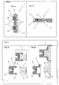
- FIG. 1a and 1b two embodiments of the device according to the present invention are shown.
- FIG. 2a and 2b two alternative devices are shown, each in a status prior and after assembly.
- a device of the present invention is useful in receiving a fluid or/and storing a fluid or/and chemically or physically treating a fluid, or / and analyzing a fluid.
- Said fluid can be a sample, a reagent, a diluent or a process fluid or a combination thereof or a fluid derived therefrom. It can be liquid or gaseous.
- the size of the device according to the invention is mainly determined by the amount of fluid to be held or processed in the device and by the kind and number of steps to be performed.
- the device is used as a means to isolate components of the fluid.
- the component(s) to be isolated will be retained in the device, while the remainder of the liquid is allowed to exit the device.
- the volume of the liquid may exceed the volume of the cavity in the device. This allows the device to be comparably small.
- the total volume assumed by the device will be preferably between 100 ⁇ l and 10 ml.
- the device will be only slightly larger than the volume of the fluid and of any reagents intended to be reacted with the fluid.
- volumes of fluids preferably have a volume of more than 0.1 ⁇ l, preferably between 0.2 ⁇ l and 1L
- the volume of the device will exceed 200 ⁇ l, preferably be between 200 ⁇ l and 1.1 L, and most preferably will be between 500 ⁇ l and 110 ml.
- the device has a substantially flat structure, i.e. in its main part it has a thickness of less than 50 mm, preferably of between 0.2 and 10 mm, a length and width of less than 300 mm, preferably of between 2 and 150 mm. If parts of the device need larger thickness, this part may exceed over the substantially flat structure.
- the device For receiving and maintaining a fluid, the device has a body, which further contains one or more cavities, which temporarily or continuously receive or/and maintain the fluid or a fluids derived therefrom.
- the body of the device is formed from at least one relatively rigid polymer.
- Polymers for the body according to the present invention are preferably selected from the group of thermoplastic material, for example, polypropylene, polyethylene, polystyrene, polycarbonate and polymethylmethacrylate.
- the body is made of a material, which can be liquefied by heating above its melting temperature, and which in molten state can be introduced into a mold to reflect the particular form the body or a part thereof is intended to assume.
- the device according to the invention comprises a cavity.
- Typical volumes of the cavity can range from 1 ⁇ l to 1L, preferably from 100 ⁇ l to 100 ml.
- This cavity can have different forms adapted to the various intended uses of the device.
- the cavity can be divided into multiple sections having channels and chambers.
- a preferred cavity contains one or more channels or/and one or more chambers,.
- the cavity comprises two or more channels, one leading to the chamber, and one leading away from the chamber.
- the cavity has a volume of less than 1 L, preferably between 1 ⁇ l and 100 ml.
- Channels formed within the device, particularly in the device, preferably the body preferably have a cross section of less than 10 mm 2 , preferably of between 0.01 and 2mm 2 .
- Cavities formed within the body preferably have dimensions suitable for the intended use of the process.
- Channels for transporting fluids through the device will preferably have smaller dimensions than chambers for keeping the fluids or/and performing a process, preferably a chemical reaction.
- a chamber for separating nucleic acids from a fluid will preferably have a volume of between 5 and 100 ⁇ l.
- a chamber for performing polymerase chain reaction may have a volume of between 0.1 and 500 ⁇ l. If combined amplification and detection is intended to be made in the chamber, the chamber preferably will have a volume of between 0.1 and 500 ⁇ l.
- the depth of a preferred substantially flat chamber will be between 10 ⁇ m and 49 mm, preferably between 10 ⁇ m an 20 mm, while the length and breadth of the chamber may be between 10 ⁇ m and 295 mm, preferably between 20 ⁇ m and 145 mm.
- the chambers are flat chambers of a thickness of less than 2000 ⁇ m, preferably between 50 ⁇ m and 5 mm. Most preferable, the thickness is between 50 ⁇ m and 1 mm.
- a first channel formed in the body will preferably lead from an input location into a chamber and a second channel will preferably lead from said chamber to an outlet location on the device.
- a second channel will preferably lead from said chamber to an outlet location on the device.
- chambers and channels are arranged such that any liquid introduced through an inlet channel into said chamber will fill said chamber prior to leaving the chamber through an outlet channel.
- Parts of the cavity may contain inserted materials, so called “solid phases", which may be used for adsorption, filtration and/or reactions on the surface.
- the cavity is closed by the body carrying the fluid port and a sealing wall attached to the body.
- the final device is then generally a composite of several elements. This means it consists of two or more parts manufactured separately and assembled subsequently, at least one part of the device consisting of the 2-compound injection molded part, having a rigid body and an elastomeric fluid port adhering to said body. Because it has proven to be difficult to manufacture a body comprising a cavity suitable for chemical analyses in one piece, it is preferred that the device is made of two or more parts, which are combined to create the one or more cavities.
- the device comprises a first element called “body” carrying the fluid port, and a second element called “sealing wall", the body having grooves or/and channels.
- the rigid body provides the stiffness to the device to maintain the shape of the cavity throughout the process of manufacture and use of the device.
- the thin foil or/and the body have more than 2 % transmission for an electromagnetic wave with a wavelength in a range from 300 to 4000 nm.
- the two parts - body and sealing wall- can be joined by known methods.
- the sealing wall is a thin layer and the rigid body is made of polymer, e.g. polystyrene
- the two parts can be combined and then sealed by welding, for example LASER welding, ultrasound welding, thermo sealing or gluing.
- the two parts can also only be clamped or stick together. In case of clamping or sticking the parts together the elastomeric part can be used as sealing part between the body and the sealing wall.
- the joining method, the material of body and the material of the sealing wall have to be selected to fit together.
- the joining method is Laser welding
- the bulk material of the body and the sealing wall are of the same material (e.g. polypropylene) but one of the two materials is stained to have an absorption for the laser energy.
- the joining method is ultrasound welding both materials are typically the same.
- thermo sealing the sealing wall is a thermo sealable foil adapted to thermically seal to the body.
- thermo sealable foils are generally composites of several materials, wherein the layer opposed to the sealing is able to seal to the body.
- a typical foil suitable to be joined to a polypropylene body has composite layers of aluminum or polyester and polypropylene.- Such sealing foils are known and are commercial available.
- the sealing wall is a foil
- the foil preferably is thin and is between 20 and 1000 ⁇ m thick, more preferably between 50 and 250 ⁇ m.
- the foil has a good heat transfer rate e.g. of more then 400 W/m 2 /K, more preferred of more than 200 W/m 2 /K.
- the device can contain further elements that may be useful for the intended purpose of the device.
- heat transferring walls or heating elements may be integrated into either the sealing wall or the body.
- the heat transferring wall can be used to heat or/and cool fluids contained in the device.
- Electrodes can be incorporated into the body or the sealing wall. Electrodes can be used to determine the electrochemical status of fluids contained in the device or to start electrochemical reactions within the device. In this case, the device will have appropriate connectivity to electrical circuits.
- optical windows (allowing an at least partial transmission to a wavelength) can be incorporated to the body or the sealing wall.
- the device according to the present invention is designed to hold, deliver or receive a fluid.
- the device according to the present invention has one or more fluid ports.
- the device can be used for holding a fluid within the cavity, more preferable in one or more cavities.
- a fluid contained in the device can also be delivered to the outside, for example, by forcing the fluid to quit the cavity through the fluid port in the device.
- This fluid port can be the same or a different fluid port used to introduce the fluid into the device.
- the device has two or more fluid port, at least one being closed according to the invention. More preferably, two or more and most preferable all fluid ports in the device are closed using a fluid port made of an elastomer.
- Forcing a liquid out of the device may require asserting pressure to force the liquid through the fluid port, or may require applying negative pressure or even a vacuum to the cavity. This can be done by entering a rigid fluid removal actuator through a fluid port in the device and applying negative pressure through that actuator. One or more or even all of those openings are closed by the fluid port.
- the fluid port formed from the elastomeric material may have a recess on the outer side.
- This recess has at least on parts of it a conical shape, where the angle shown in Fig. 1, (W) is in the range of from 5 to 150°, more preferably between 15 and 90 °.
- the fluid port is made of an elastomer, which is shaped in a 2-compound (2C) injection molding process.
- the material of the elastomer is preferably selected from the classes of thermoplastic elastomers (TPE), thermoplastic vulcanicates (TPV), or vulcanizible elastomers (VE), materials which are generally used in 2C injection molding processes.
- TPE thermoplastic elastomers
- TPV thermoplastic vulcanicates
- VE vulcanizible elastomers
- thermoplastic elastomers are useable as finally (at room temperature) elastomeric materials, e.g. elastomeric thermoplastic polyolefins (TPO) or elastomeric thermoplastic polyurethanes (TPU) or elastomeric styrol-block-copolymers (SBS, SEBS).
- TPO elastomeric thermoplastic polyolefins
- TPU elastomeric thermoplastic polyurethanes
- SBS elastomeric styrol-block-copolymers
- TPVs thermoplastic vulcanicates, which are a special class of TPE containing a cross linked rubber phase dispersed within a thermoplastic polymer phase, can be used. TPVs offer elastomeric characteristics similar to cross linked rubbers, but are processable as thermoplastic polymers.
- a preferred material combination is the combination of polypropylene as rigid material and TPO as elastomeric material.
- the elastomer is selected to fit the fabrication (2 compound injection molding process) and is selected to have a certain adhesion to the material of the body.
- Typical adhesion force between the rigid body and the elastomeric fluid port is at least 0.1 N, typically more than 1 N.
- thermoplastic elastomer has the property to liquefy when heated to a temperature above its melting point without decomposition, and when cooled to a temperature below its melting point will solidify reflecting the geometrical form of the mold in which it is kept.
- a preferred thermoplastic elastomers used in combination with polypropylene as rigid material is from the company _"Advanced Elastomer Systems" the TPE Santopren® 8281W-35W-237.
- a preferred group of thermoplastic elastomers has a processing temperature between 180 and 220°C. The elastomer has in its final shape and usage temperature a Shore hardness of 0A to 100A, preferably in a range from 20A to 60A.
- the elastomeric fluid port forms a pierceable barrier between the cavity and the outside.
- the elastomeric fluid port protects the cavity in the device from contamination from the environment and vice versa, fluids stored, processed or analyzed in the device can not contaminate the environment.
- the fluid port is construed such that it reliably closes the cavity in the device, but has dimensions allowing piercing of the fluid port with a rigid fluid actuator, preferably a pipette tip or a hollow steel needle from outside of the device, such that after piercing fluid can be introduced from the actuator into or out of the cavity of the device through the fluid port.
- a fluid port according to the invention covers one end of a channel that would, if not covered, be freely accessible to fluids from the surface of said body. In this case, the fluid will be introduced through the actuator into or our out of the cavity present in the device, preferably through a channel in the device leading to a chamber.
- a fluid port (4) or two fluid ports (4), are located on a flat side of the device (1).
- the one or more fluid ports are provided on the body side of the device, i.e. leading from the flat side into the cavity (3) through the body.
- the fluid port can be pierced from the flat side of the device.
- the at least one fluid port (4) is located on one side of the body, the fluid port being made of a thermoplastic elastomer adhering to said body.
- the fluid port here on one side forms a wall to the ambient (especially to be interfaced by a fluid actuator) and on the opposite side it forms a wall to the cavity.
- two fluid ports are shown interfacing a common cavity in the device.
- the fluid port forms a wall to the ambient (especially to be interfaced by fluid actuator), but supplementally to the embodiment shown in Fig. 1a harbours on the opposite side a cavity (leading to further cavities located in the rigid material).
- this cavity harboured in the thermoplastic elastomer is a channel leading in a direction which is orthogonal to the direction of the fluid actuator interfacing.
- the material forming the fluid port is made of is an thermoplastic elastomer adhering to the body.
- the two cavities can be connected via a channel that is not in plain with those cavities, but leads from one plain to the other.
- the material making up the fluid port i.e. the elastomeric material, contains a channel through which the actuator or the fluid can enter the cavity.
- Said channel preferably is in the direction orthogonal to the movement of the actuator when piercing the port.
- the body has the form of a cap and the cavity (3) is partially or completely contained within the sealing wall (5).
- the body cap is shown above a part of the sealing wall (only partial view of the whole device, showing the fluid port section of the device).
- the body further comprises a snap mechanism (6), while the sealing wall contains a snap-in recess (7).
- the assembled device is shown, wherein the rigid carrier is firmly connected to the sealing wall. In the present case, the connection is made by a form fit, particularly a snap-in connection.
- a sealing rim (8) on the sealing wall (5) is provided that compresses the fluid port so as to provide a fluid tight connection between the body and the sealing wall.
- the body is again used as a cap to close an opening in the sealing wall.
- this embodiment is held together using a glue or by welding.
- the use of an elastomer, which is shaped in a 2C injection molding process as the fluid port has the advantage, that the materials can be selected that they adhere to each other.
- This adhesion between the body and the fluid port is achieved by the characteristics of the material of the rigid body and the material of the elastomeric fluid port.
- the elastomer In the molten state, the elastomer can be brought into a form, which tightly adheres to the body and seals any openings in the body.
- This form may have projections and recesses that reach into recesses in or surround projections in the body, particularly in the vicinity of the fluid port. Therefore, the force fit preferably is made via surfaces having an angle formed by the outer surface of the carrier and the surface of the carrier used for connection with the fluid port.
- the force fit has the effect that the fluid port is tightly connected to the body, so that even when piercing the fluid port using a rigid fluid delivery actuator such as a steel needle and withdrawing the actuator from the fluid port after dispensing of a fluid into the cavity, the connection between the fluid port and the body is still impervious to the fluid.
- a rigid fluid delivery actuator such as a steel needle
- the fluid port of the present invention is not intended and not constructed to be removed from the device.
- the fluid port of the present invention cannot be removed from the body without seriously damaging the device, i.e. disrupting the integrity of the device.
- the intended function in this connection is a sufficient separation of the devices inside (cavities) and the devices outside, mainly to avoid undesired or uncontrolled or excess transport of mater from the environment to the devices inside and vice versa.
- Such a mass transport can be pressure driven, diffusions driven or by any other mechanism e.g. gravity driven (dust).
- the elastomer which is shaped in a 2C injection molding process preferably, allows piercing of the fluid port.
- Piercing causes an introduction of a rigid fluid delivery actuator, such as steel cannula and passing an opening in the cannula into the cavity. By allowing this access, the fluid port is broken at the site, where the actuator enters and passes the fluid port.
- the fluid port may be pre-pierced, but the pierced path is closed by repulsing forces of the elastomer.
- the device is tight (means sufficient closed to a transport of matter in or out of the device)
- the fluid port is generally designed to avoid an uncontrolled transport of matter in or out of the cavity.
- the thickness of the elastomeric fluid port is in a range of 0.1 mm and 40 mm, more preferably in a range of from 1 to 10 mm.
- a sufficient diameter of the elastomer is required. Therefore at least at one point of the piercing path a diameter of the elastomer must be > 3 times the diameter of the fluid actuator.
- a preferred embodiment of the fluid port is a self-sealing port, i.e. a port allows self-sealing closing of the space between the fluid actuator and the fluid port, such that fluid cannot escape. Furthermore, after removal of the actuator, the fluid port still closes the opening of the body and the piercing path does not allow fluid to escape the device even at a differential pressure of 1 bar.
- the device is a micro fluidic device.
- Micro fluidic devices according to the here used understanding have one or more channels with a cross section of more than 0.1 ⁇ m 2 , more preferable between 10 ⁇ m 2 to 10 mm 2 .
- Micro fluidic devices may furthermore or alternatively comprise one or more chambers having a larger cross section larger than the channels.
- the chamber of a micro fluidic device may have a volume of between 10 nl and 50 ml, more preferable between 1 ⁇ l and 25 ml.
- the device may also have fluidic or micro fluidic functions. Those functions are generally known to be means for physically treating the fluid in said cavity. Those can be static elements, like fittings, comprising walls and surfaces, for example for mixing, dividing or combining of fluids. Other functions that may be provided by the cavity are optical functions. For this reason, the body around said cavity, preferably a chamber, is transparent to allow entering or/and escaping light from the cavity to the outside of the device. Preferably, the cavity has dimensions that allow collecting fluid in an amount that is sufficient for reliable detection of components contained in the fluid. Another function of the cavity may be to receive materials to react with the fluid.
- Such materials may be selected from the group of soluble or insoluble reagents, or combinations thereof, or both, even in separate parts of the cavity, or chambers.
- Soluble reagents may be reagents to support lysis of a sample, to amplify a nucleic acid contained in the sample or a liquid derived therefrom, or to provide a signal when reacting with the components of the sample to be determined.
- Insoluble reagents may be solids that are designed to immobilize components of the fluid, or compounds derived therefrom. Examples for nucleic acid immobilizing solids are glass fleece or magnetic particles, which are capable to bind nucleic acids from a chaotropic solution. Appropriate materials are known to the person skilled in the art of nucleic acid sample preparation.
- the fluid port is located in the device such as to be accessible to a rigid fluid actuator from outside of the device. This can be done by constructing the device such that there are no elements of the device hindering movement of the actuator in direction to and finally through the fluid port. Practically, the fluid ports will be located on a flat surface of the device.
- the device may further comprise surfaces guiding the actuator to the point in the fluid port, at which the breakage of the fluid port by the actuator is intended. Such surfaces can be provided either on the body or on the fluid port.
- the guiding surfaces are shown in the figures with reference numeral 9. The guiding surfaces most preferably have the form of a conus, getting smaller towards the position of the fluid port to be pierced.
- a fluid that can be received, held or delivered in the device according to the present invention can be any fluid that is of interest to be subject to a particular treatment.
- the fluid is a liquid. More preferable, the liquid is an aqueous solution.
- components of the liquid are intended to be treated or analyzed. In a diagnostic device, the liquid contains components to be determined in an analysis.
- Such liquids can be selected from the group of environmental fluids, like water from a river or a fluid extracted from soil, food fluids, like a juice or an extract from a plant or fruit, or a fluid received from animal or human body, like blood, serum, plasma, urine, cerebrospinal fluid or lymphatic fluid, or liquid derived therefrom, like liquids containing components isolated from the before mentioned liquid, like liquids containing purified antibodies or nucleic acids.
- the liquid further can contain additional components useful for the analysis of components of the liquid or reagents for chemical reactions to be performed within the device.
- Those reagents can comprise labelled binding partners, for instance labelled oligonucleotide probes or dyes.
- a further subject of the present invention is a method for manufacturing a device having a rigid body comprising a first, rigid material comprising a cavity and a fluid port being of a second, elastic material, comprising
- the device is a device as described above.
- the first, rigid material e.g. for the manufacture of the body, preferably is a material selected from the group of thermoplasts. Particularly preferred are polypropylene, polyethylene, polystyrene, polycarbonate and polymethylacrylate. Those are the materials that are the preferable materials for forming one or more parts of the body of the device as described above.
- a mold is provided to reflecting an outer form of the body. Molds for injection molding processes are generally known and used in the art.
- the mold preferably consist of metallic or ceramic mold, preferably comprising a cavity having one or more fluid ports for filling the mold with the liquefied material.
- the mold preferably is made from two or more parts that are connected during the molding process and can be separated after solidification of the material in the mold.
- the result of the molding process can be removed from the mold.
- the final form of the result of the molding process will be determined by the shape of the mold.
- grooves in the outer surface of the result of the molding process are generated by protrusions into the cavity of the mold.
- Channels through the result of the molding process e.g. the body, like those channels leading from one side of the carrier containing a chamber to the other side of the carrier having the opening, are generated by a rod connecting a first part of the mold with a second part of the mold.
- the first, finally rigid material is liquefied by heating it to a temperature above the melting temperature.
- the material is then injected into the cavity of the mold, preferably by applying pressure and allowing the air contained in the cavity to escape through a fluid port different from the fluid port through which the material is injected.
- the result of the first molding step will be the subject of a second molding process using the second material.
- the first material has become at least partially solid. More preferably, the temperature of the first material has fallen or been reduced to a temperature below melting point. This can be done by active or passive cooling.
- a part of the mold covering the surface of the form resulting from the first molding step is removed, in order to allow access of liquefied second material to said surfaces.
- a second mold is connected to the remaining part of the first mold, reflecting the outer form of the fluid port. This will form a cavity within the finally assembled mold reflecting the outer form of the fluid port as connected to the body of the device.
- the result of the first molding step is removed from the first mold and introduced into a second mold, which reflects the form of the body surrounding the part of the fluid port to be produced and a second part reflecting the outer form of the fluid port to be molded onto the result of the first molding step.
- This cavity of the second mold is then filled with the second material liquefied by injection.
- the process can be performed in an alternative way, generally changing the order of the molding steps.
- a mold reflecting an outer form of the fluid port is provided, analogous as described above for the rigid material, the second material in liquefied form is injected, and after partial or total solidification of the second material, a second molding step is performed using the first, rigid material in liquefied form in a second mold.
- Another subject of the invention is a method for manufacturing a device having a body comprising a first, rigid material comprising a cavity and a fluid port being of a second, elastic material, comprising
- any cavities can be sealed in additional steps, preferably by applying a sealing wall to the result of the molding steps, that sealing wall confining a wall of that cavity in the body, for example completing the form of one or more channels or/and chambers.
- This can be done by connecting surfaces of the sealing wall and the result of the molding steps tightly and gluing or welding the materials together.
- Preferred modes of connecting a carrier and a sealing wall are LASER welding, ultrasound welding, thermo sealing or gluing.
- Another subject of the present invention is a system for analysis of a liquid comprising
- Instruments for analysis of a fluid are generally known. Those include the modules generally required for analyses. Preferred modules for such instruments are optics for determining optical properties or changes in optical properties of the liquid, mechanics to move the liquid from a first position to one or more other positions, and liquid handling modules for dispensing or/and aspirating fluids from tubes, vessels or reagent containers.
- the system according to the invention requires a rigid fluid actuator, which is used to dispense fluid into the device according to the invention or/and remove liquid from the device.
- the function of dispense or deliver and remove or receive fluid to and from the device is according to the invention to be considered both as active and passive handling.
- receiving a fluid from a first rigid actuator can be made by either applying the fluid under pressure to the device to press the fluid into the device or by applying negative pressure to the cavity so as to suck fluid into the device and removing or delivering fluid from the device to the outside can be achieved by either applying pressure to the cavity, e.g. by pumping a fluid, such as a liquid or a gas through a first fluid port, or applying negative pressure to the cavity so as to suck the fluid through an fluid port.
- a rigid fluid actuator useful in the present invention is a device having three characteristics. It must be capable of piercing the fluid port of the device. This is achieved by a certain rigidity. The required rigidity is provided by using e.g. metals for this actuator. Preferably, the device designed as a tip to break the seal. Furthermore, the device needs to be as long as to reach through the fluid port into the interior of the device. Thus, the device has preferably an elongated and thin shape. Thirdly, the device must provide a channel to transfer the liquid in or out of the device. Thus, cannulas or cannula-shaped or hollow needle-like devices are preferred. The outer diameter of the fluid actuator can be in a range of 0.1 to 3 mm, more preferred in a range of 0.2 to 1.5 mm, most preferred in range of 0.3 to 0.8 mm.
- the device is preferably used in an instrument.
- the instrument contains in fluidic communication with the fluid actuator means to apply positive or negative pressure to deliver or to receive fluid.
- Appropriate means include syringe pumps.
- the fluid actuator position relatively to the device may be controlled by an automatic system.
- the instrument further contains supplemental means to perform an analysis, e.g. a heating element.
- a heating element is positioned such that it can contact the device at a position, wherein the heat can be used to heat up fluid within the device, preferably when the fluid is contained in a cavity within the device.
- An example of an instrument comprising a heating element is a thermocycler. Thermocyclers are generally known to apply a profile of different temperatures in repeated manner to a fluid. An exemplary thermocycler is described in EP 236 069 .
- Preferred heating elements are Peltier elements or resistance heating elements.
- the instrument further can comprise a detection module.
- detection modules are generally known and depend upon the kind of property or property change performed during the presence of the liquid in the device.
- the detection module will comprise a light source positioned in the instrument such that the device, preferably a chamber in that device, can be irradiated, and an irradiation receiving unit, preferably a light sensitive cell for receiving irradiation from the liquid contained in the device and transmitting an electrical signal to an evaluation unit.
- such connectors are preferably provided on the instruments on positions that are located such that the connectors on the instrument are connected to their counterparts on the device, when the device is inserted into the instrument.
- the system according to the invention comprises in addition a fluid container (e.g. for waste collection) or/and one or more reagent containers.
- a fluid container e.g. for waste collection
- one or more reagent containers e.g. for reagent containers
- a further subject of the invention is the use of a device according to the invention in a method for analysis of a sample e.g. in an in-vitro diagnostic test. Therefore, another subject of the present invention is a method of analysis of a sample or components thereof using one or more reagents comprising
- the device already contains reagents useful for the analysis, and the sample is introduced through the fluid port.
- the device contains a sensor which is useful for determining a property of the sample or the liquid derived therefrom, using or not using reagents.
- the fluid preferably a sample to be analyzed or/and reagents, is preferably introduced into the device by a rigid fluid actuator such as a steel cannula through a first fluid port into a channel leading to a chamber.
- the chamber further contains at its end opposite to the inlet point of the first channel an outlet point for a second channel, said second channel leading to a second opening, that second opening being closed by another fluid port as described above.
- a second cannula While applying pressure to the liquid in the cannula to enter the channel, a second cannula is present pierced through that second fluid port such that the pressure can escape through that second cannula.
- the liquid contains the fluid to be analyzed as well as all reagents needed for analysis of the components of the fluid to be detected, such as a labeled binding partner for the component to be determined in the fluid.
- the liquid is proceeded into the cavity by applying pressure through the first cannula or by applying negative pressure to the second cannula. Detection can start in the chamber, when the reaction has proceeded as required. This can be made by irradiating the liquid in the cavity with light of a wave length at which one of the components or reagents in the fluid has a measurable absorption.
- Determination of light leaving the cavity can be used to determine the absorbance of the liquid or any changes in absorbance of the liquid over time or compared to a standard liquid.
- the component of the liquid to be analyzed is a nucleic acid suspected to be contained in a fluid, for example, parts of the genome of hepatitis C virus.
- the reagents for analysis will then contain primers for the amplification of a particular fragment of said nucleic acid and a probe for binding to the amplified fragment.
- a very preferred embodiment of such reaction is disclosed in EP 543 942 .
- the instrument used contains a combined heating/cooling block to bring the content of the chamber to the temperature in a profile as needed to amplify the nucleic acids.
- An advantage of the device according to the present invention is that the interface between the device and the closure of the device is very tight. This allows the application of high pressure to the inside of the device, for example, when the cavity within the device has channels of very small dimension or/and the use of liquids, which tend to clot during transport or reaction in a micro fluidic device.
- An advantage of the manufacturing device is that using this method it is possible to provide a device which is tightly sealed.
- the device according to the invention can be very advantageously used in systems for analysis of a liquid, as due to the tightness of the sealing, the instrument is better protected from contamination by fluid escaping the device, and on the other hand the interior of the device is protected from contamination from the ambience.
- Using the device according to the invention furthermore leads to increased convenience in analyses, as analysis can be automated using automated fluid delivery through a rigid fluid actuator. In addition, particularly for small devices, manufacturing gets more simple and reliable.
Landscapes
- Chemical & Material Sciences (AREA)
- Health & Medical Sciences (AREA)
- Clinical Laboratory Science (AREA)
- Analytical Chemistry (AREA)
- General Health & Medical Sciences (AREA)
- Hematology (AREA)
- Dispersion Chemistry (AREA)
- Chemical Kinetics & Catalysis (AREA)
- Engineering & Computer Science (AREA)
- Manufacturing & Machinery (AREA)
- Mechanical Engineering (AREA)
- Automatic Analysis And Handling Materials Therefor (AREA)
- Sampling And Sample Adjustment (AREA)
Priority Applications (2)
| Application Number | Priority Date | Filing Date | Title |
|---|---|---|---|
| EP11180230A EP2415524A2 (de) | 2005-03-30 | 2006-03-28 | Abgedichtete Vorrichtung |
| EP06006352A EP1710016A3 (de) | 2005-03-30 | 2006-03-28 | Vorrichtung mit selbstdichtendem Einlass |
Applications Claiming Priority (2)
| Application Number | Priority Date | Filing Date | Title |
|---|---|---|---|
| EP05102477A EP1707267A1 (de) | 2005-03-30 | 2005-03-30 | Vorrichtung mit selbstdichtendem EInlass |
| EP06006352A EP1710016A3 (de) | 2005-03-30 | 2006-03-28 | Vorrichtung mit selbstdichtendem Einlass |
Publications (2)
| Publication Number | Publication Date |
|---|---|
| EP1710016A2 true EP1710016A2 (de) | 2006-10-11 |
| EP1710016A3 EP1710016A3 (de) | 2011-03-30 |
Family
ID=37772683
Family Applications (2)
| Application Number | Title | Priority Date | Filing Date |
|---|---|---|---|
| EP06006352A Withdrawn EP1710016A3 (de) | 2005-03-30 | 2006-03-28 | Vorrichtung mit selbstdichtendem Einlass |
| EP11180230A Withdrawn EP2415524A2 (de) | 2005-03-30 | 2006-03-28 | Abgedichtete Vorrichtung |
Family Applications After (1)
| Application Number | Title | Priority Date | Filing Date |
|---|---|---|---|
| EP11180230A Withdrawn EP2415524A2 (de) | 2005-03-30 | 2006-03-28 | Abgedichtete Vorrichtung |
Country Status (1)
| Country | Link |
|---|---|
| EP (2) | EP1710016A3 (de) |
Cited By (5)
| Publication number | Priority date | Publication date | Assignee | Title |
|---|---|---|---|---|
| US8256285B2 (en) | 2007-08-21 | 2012-09-04 | BELIMO Holding, AG | Flow sensor including a base member with a resilient region forming a flow channel and a cover member covering the flow channel |
| EP2647435A1 (de) * | 2012-04-05 | 2013-10-09 | ThinXXS Microtechnology AG | Flusszelle mit einer Temperierkammer |
| WO2013166106A1 (en) * | 2012-05-04 | 2013-11-07 | Siemens Healthcare Diagnostics Inc. | Sample introduction system |
| CN104229724A (zh) * | 2013-06-09 | 2014-12-24 | 中国科学院物理研究所 | 一种制备自封闭纳米通道的方法 |
| WO2015015176A1 (en) * | 2013-07-29 | 2015-02-05 | Atlas Genetics Limited | Fluid control device and method of manufacture |
Citations (6)
| Publication number | Priority date | Publication date | Assignee | Title |
|---|---|---|---|---|
| EP0236069A2 (de) | 1986-02-25 | 1987-09-09 | The Perkin-Elmer Corporation | Vorrichtung und Verfahren zur Durchführung der automatischen Amplifizierung von Nukleinsäuresequenzen und Assays mit Heiz- und Kühlschritten |
| EP0543942A1 (de) | 1990-08-06 | 1993-06-02 | F. Hoffmann-La Roche Ag | Homogenes testsystem |
| EP0724483A1 (de) | 1993-10-22 | 1996-08-07 | Abbott Laboratories | Teströrchen und verfahren zur minimisierung der kontamination |
| EP0907083A1 (de) | 1997-10-02 | 1999-04-07 | F. Hoffmann-La Roche Ag | Automatische Handhabung von mit einer abschraubbaren Kappe verschlossenen Probenbehältern |
| US6537501B1 (en) | 1998-05-18 | 2003-03-25 | University Of Washington | Disposable hematology cartridge |
| US20030138969A1 (en) | 2002-01-24 | 2003-07-24 | Jakobsen Mogens Havsteen | Closed substrate platforms suitable for analysis of biomolecules |
Family Cites Families (3)
| Publication number | Priority date | Publication date | Assignee | Title |
|---|---|---|---|---|
| CA2015571A1 (en) * | 1990-04-26 | 1991-10-26 | Samco Scientific, Inc. | Reinsertable closure for sample tubes |
| JP3142521B2 (ja) * | 1998-11-04 | 2001-03-07 | 大成プラス株式会社 | 針刺し止栓とその製造方法 |
| DE10308727B3 (de) * | 2003-02-28 | 2004-06-09 | Krauss-Maffei Kunststofftechnik Gmbh | Verbundbauteil mit teilbeweglichen Elementen und Verfahren zu dessen Herstellung |
-
2006
- 2006-03-28 EP EP06006352A patent/EP1710016A3/de not_active Withdrawn
- 2006-03-28 EP EP11180230A patent/EP2415524A2/de not_active Withdrawn
Patent Citations (6)
| Publication number | Priority date | Publication date | Assignee | Title |
|---|---|---|---|---|
| EP0236069A2 (de) | 1986-02-25 | 1987-09-09 | The Perkin-Elmer Corporation | Vorrichtung und Verfahren zur Durchführung der automatischen Amplifizierung von Nukleinsäuresequenzen und Assays mit Heiz- und Kühlschritten |
| EP0543942A1 (de) | 1990-08-06 | 1993-06-02 | F. Hoffmann-La Roche Ag | Homogenes testsystem |
| EP0724483A1 (de) | 1993-10-22 | 1996-08-07 | Abbott Laboratories | Teströrchen und verfahren zur minimisierung der kontamination |
| EP0907083A1 (de) | 1997-10-02 | 1999-04-07 | F. Hoffmann-La Roche Ag | Automatische Handhabung von mit einer abschraubbaren Kappe verschlossenen Probenbehältern |
| US6537501B1 (en) | 1998-05-18 | 2003-03-25 | University Of Washington | Disposable hematology cartridge |
| US20030138969A1 (en) | 2002-01-24 | 2003-07-24 | Jakobsen Mogens Havsteen | Closed substrate platforms suitable for analysis of biomolecules |
Cited By (9)
| Publication number | Priority date | Publication date | Assignee | Title |
|---|---|---|---|---|
| US8256285B2 (en) | 2007-08-21 | 2012-09-04 | BELIMO Holding, AG | Flow sensor including a base member with a resilient region forming a flow channel and a cover member covering the flow channel |
| EP2647435A1 (de) * | 2012-04-05 | 2013-10-09 | ThinXXS Microtechnology AG | Flusszelle mit einer Temperierkammer |
| US9149802B2 (en) | 2012-04-05 | 2015-10-06 | Thinxxs Microtechnology Ag | Flow cell with a temperature-control chamber |
| WO2013166106A1 (en) * | 2012-05-04 | 2013-11-07 | Siemens Healthcare Diagnostics Inc. | Sample introduction system |
| US9726582B2 (en) | 2012-05-04 | 2017-08-08 | Siemens Healthcare Diagnostics Inc. | Sample introduction system |
| US10281373B2 (en) | 2012-05-04 | 2019-05-07 | Siemens Healthcare Diagnostics Inc. | Sample introduction system |
| CN104229724A (zh) * | 2013-06-09 | 2014-12-24 | 中国科学院物理研究所 | 一种制备自封闭纳米通道的方法 |
| CN104229724B (zh) * | 2013-06-09 | 2016-04-13 | 中国科学院物理研究所 | 一种制备自封闭纳米通道的方法 |
| WO2015015176A1 (en) * | 2013-07-29 | 2015-02-05 | Atlas Genetics Limited | Fluid control device and method of manufacture |
Also Published As
| Publication number | Publication date |
|---|---|
| EP1710016A3 (de) | 2011-03-30 |
| EP2415524A2 (de) | 2012-02-08 |
Similar Documents
| Publication | Publication Date | Title |
|---|---|---|
| AU2006201256B2 (en) | Device having a self sealing fluid port | |
| EP1427531B1 (de) | Probenbehälter | |
| EP2179294B1 (de) | Probenbearbeitungsgerät | |
| JP6272895B2 (ja) | デバイスおよび装置 | |
| US20030049833A1 (en) | Sample vessels | |
| US8642293B2 (en) | Disposable device for analyzing a liquid sample containing a nucleic acid with a nucleic acid amplification apparatus | |
| AU2002341644A1 (en) | Sample vessels | |
| EP2040839B1 (de) | Wegwerfvorrichtung zur analyse einer flüssigkeitsprobe durch nukleinsäureamplifikation | |
| EP1710016A2 (de) | Vorrichtung mit selbstdichtendem Einlass | |
| EP2298449B1 (de) | Vorrichtung zur Analyse | |
| WO2018065107A1 (en) | Cartridge for testing a sample and method for producing a cartridge of this kind | |
| JPWO2008096570A1 (ja) | マイクロチップ、およびマイクロチップ検査システム | |
| US20080011062A1 (en) | Device with insert for analytical systems | |
| JP2014098595A (ja) | サンプル液注入用具及びサンプル液熱処理装置 |
Legal Events
| Date | Code | Title | Description |
|---|---|---|---|
| PUAI | Public reference made under article 153(3) epc to a published international application that has entered the european phase |
Free format text: ORIGINAL CODE: 0009012 |
|
| 17P | Request for examination filed |
Effective date: 20060328 |
|
| AK | Designated contracting states |
Kind code of ref document: A2 Designated state(s): AT BE BG CH CY CZ DE DK EE ES FI FR GB GR HU IE IS IT LI LT LU LV MC NL PL PT RO SE SI SK TR |
|
| AX | Request for extension of the european patent |
Extension state: AL BA HR MK YU |
|
| PUAL | Search report despatched |
Free format text: ORIGINAL CODE: 0009013 |
|
| AK | Designated contracting states |
Kind code of ref document: A3 Designated state(s): AT BE BG CH CY CZ DE DK EE ES FI FR GB GR HU IE IS IT LI LT LU LV MC NL PL PT RO SE SI SK TR |
|
| AX | Request for extension of the european patent |
Extension state: AL BA HR MK YU |
|
| STAA | Information on the status of an ep patent application or granted ep patent |
Free format text: STATUS: THE APPLICATION HAS BEEN WITHDRAWN |
|
| 18W | Application withdrawn |
Effective date: 20110907 |