EP1709772B1 - Verfahren und anordnung für eine verbesserte pufferlösung in einem kommunikationsnetzwerk-switch - Google Patents
Verfahren und anordnung für eine verbesserte pufferlösung in einem kommunikationsnetzwerk-switch Download PDFInfo
- Publication number
- EP1709772B1 EP1709772B1 EP05704639.3A EP05704639A EP1709772B1 EP 1709772 B1 EP1709772 B1 EP 1709772B1 EP 05704639 A EP05704639 A EP 05704639A EP 1709772 B1 EP1709772 B1 EP 1709772B1
- Authority
- EP
- European Patent Office
- Prior art keywords
- data
- packets
- node
- buffer
- length
- Prior art date
- Legal status (The legal status is an assumption and is not a legal conclusion. Google has not performed a legal analysis and makes no representation as to the accuracy of the status listed.)
- Expired - Lifetime
Links
- 238000000034 method Methods 0.000 title claims description 12
- 238000004891 communication Methods 0.000 title claims description 11
- 239000007853 buffer solution Substances 0.000 title 1
- 239000000872 buffer Substances 0.000 claims description 59
- 230000003287 optical effect Effects 0.000 claims description 19
- 230000003139 buffering effect Effects 0.000 claims description 17
- 230000002776 aggregation Effects 0.000 claims description 2
- 238000004220 aggregation Methods 0.000 claims description 2
- 238000012544 monitoring process Methods 0.000 claims description 2
- 238000004422 calculation algorithm Methods 0.000 description 8
- 238000013459 approach Methods 0.000 description 4
- 239000000835 fiber Substances 0.000 description 4
- 230000006870 function Effects 0.000 description 4
- 238000004088 simulation Methods 0.000 description 4
- 230000004931 aggregating effect Effects 0.000 description 3
- 230000005540 biological transmission Effects 0.000 description 1
- 238000004364 calculation method Methods 0.000 description 1
- 230000003111 delayed effect Effects 0.000 description 1
- 238000001514 detection method Methods 0.000 description 1
- 230000005693 optoelectronics Effects 0.000 description 1
- 230000001360 synchronised effect Effects 0.000 description 1
Images



Classifications
-
- H—ELECTRICITY
- H04—ELECTRIC COMMUNICATION TECHNIQUE
- H04Q—SELECTING
- H04Q11/00—Selecting arrangements for multiplex systems
- H04Q11/0001—Selecting arrangements for multiplex systems using optical switching
- H04Q11/0005—Switch and router aspects
-
- H—ELECTRICITY
- H04—ELECTRIC COMMUNICATION TECHNIQUE
- H04L—TRANSMISSION OF DIGITAL INFORMATION, e.g. TELEGRAPHIC COMMUNICATION
- H04L49/00—Packet switching elements
- H04L49/10—Packet switching elements characterised by the switching fabric construction
- H04L49/103—Packet switching elements characterised by the switching fabric construction using a shared central buffer; using a shared memory
-
- H—ELECTRICITY
- H04—ELECTRIC COMMUNICATION TECHNIQUE
- H04L—TRANSMISSION OF DIGITAL INFORMATION, e.g. TELEGRAPHIC COMMUNICATION
- H04L49/00—Packet switching elements
- H04L49/25—Routing or path finding in a switch fabric
- H04L49/253—Routing or path finding in a switch fabric using establishment or release of connections between ports
- H04L49/254—Centralised controller, i.e. arbitration or scheduling
-
- H—ELECTRICITY
- H04—ELECTRIC COMMUNICATION TECHNIQUE
- H04Q—SELECTING
- H04Q11/00—Selecting arrangements for multiplex systems
- H04Q11/0001—Selecting arrangements for multiplex systems using optical switching
- H04Q11/0005—Switch and router aspects
- H04Q2011/0007—Construction
- H04Q2011/002—Construction using optical delay lines or optical buffers or optical recirculation
Definitions
- the present invention relates to a switch and a method for organizing dataflow through a switch within packet switched or bursts switched networks. More particularly it relates to a switch within a telecommunication or data communication network, where the switch includes one or more outputs and a buffer unit, further it relates to a method for organizing dataflows in a telecommunication or data communication network including at least one switch where said switch is associated with at least one buffer.
- Optical Packet Switching is a promising candidate for a future cost effective network, supporting both high throughput and utilization.
- Two main issues of interest in OPS are however optical synchronization and buffering. Recently, a number of works has focused on using asynchronous packet switching, thereby avoiding the optical synchronization unit [1], [2].
- FDL Fiber Delay Line
- An alternative to FDL's is to use electronic memory with a limited number of buffer inputs [1,3]. In either case, buffer interfaces, consisting of FDL's or OE-converters (opto electronic converters), will represent a major cost factor for an optical packet switched system and should therefore be minimized [4].
- Delay through an OPS network is negligible compared to transmission delay [1]. However, if the buffer has fewer input interfaces than the total number of switch inputs, only a fraction of the packets passing through the switch will be buffered and hence, delayed [1,4].
- IP Input Priority
- BP Buffer Priority
- a detection circuit combined with a delay, e.g. a Fibre Delay Line (FDL) may be applied to first detect and then delay packets before passing the access node.
- FDL Fibre Delay Line
- this calls for extra components, both detectors and FDLs, making the principle potentially expensive.
- the FDLs will need to delay the packets longer than the duration of the longest of the new packets that enters the ring. This will impose additional delay of the packets already in the packet ring.
- Asynchronous Input Priority algorithm for VLP, that sorts buffered packets into a number of Queues in accordance with the packet length distribution, according to the present invention
- the algorithm is optimized for systems using the wavelength dimension for contention resolution with the goal of optimizing the buffer performance with respect to minimizing Packet Loss Ratio (PLR) and packet reordering.
- PLR Packet Loss Ratio
- the present invention provides arrangement within an asynchronous communication network, where the arrangement includes a node with one or more outputs and a buffer unit, said buffer unit is either an integral part of the node or an external part of the node conneted to the node.
- the arrangement is adapted to monitor wavelengths at the outputs of said node.
- the buffer unit is adapted to buffer the data and/or packets until a predefined number of wavelengths leading to a buffered packets destination is/are vacant.
- the present invention discloses a method for organizing dataflows in an asynchronous communication network including at least one switch and/or Metro access node where said switch and/or Metro access node is associated with at least one buffer and at least a dataflow that can be divided into data packets said dataflow is communicating with the switch and/or Metro access node and the data packets are buffered in the buffer.
- the method includes the steps of monitoring the wavelengths at the outputs of said switch and/ore Metro access node and buffering the data and/or packets until a predefined number of wavelengths leading to a buffered packets destination is/are vacant.
- the disclosed arrangement and method is characterised in that it is very flexible in that it employs a feedback buffer, wherein the feedback buffer can be of any kind provided it can be accessed at an arbitrary point of time.
- the queue system will be of a type where there is a number of queues and the queues are prioritizing queues where certain parameters is used to decide the amount of queues and/or the dimensioning of the queues.
- a natural choice for the criterion parameter is the length of the packets of data and/or the length of the data in other formats such as databursts, data streams or any other dataflow that can be split into packets.
- a first range of length of packets is associated with a first queue
- a second range of packet length is associated to a second queue
- a third range of packet length is associated with a third queue
- a n'th length of packets is associated with queue number n.
- IP input priority
- the described principle is intended to support applications with a high demand to packet sequence and PLR, still saving component costs. This is achieved using electronic buffering in combination with optical switching for optical packet switches. In Metro packet rings, electronic queuing systems are applied, using the buffering solution according to the present invention.
- the short packets will occupy the output-resources for a short time.
- the probability for the next packet arriving at the switch will be blocked when arriving at a random time after a short packet will therefore be lower than if the previous packet was a long packet.
- the buffered packets is divided into three queues according to the length of the packets. The number of wavelengths that needs to be vacant before scheduling packets from the queue with short packets can be lower than for the queue with the medium length packets, which again has lower demands to number of vacant wavelengths than the queue with the longest packets.
- the number of minimum vacant wavelengths before a queue is serviced can be defined as: Wv 1 , Wv 2 and Wv 3 for the three queues respectively.
- An empirical Internet packet length distribution like in [1] is assumed, and the packet length ranges for the three queues is defined, Q 1 , 40-44 bytes (B), Q 2 45-576 B and Q 3 577-1500 B.
- Wv 1 a simulation is performed for 32 wavelengths, 8 input fibres, assuming independent input sources and Poisson packet arrival, load 0.8, and set the number of buffer ports to 16.
- Wv 1 -Wv 3 is then varied while always keeping Wv 1 ⁇ Wv 2 ⁇ Wv 3 , finding the PLR as a function of mean delay of the buffered packets and the values of Wv 1 -Wv 3 .
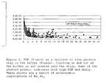
- a generic model of the simulated switch and the simulation results are shown in fig. 1 .
- the two FDL buffering schemes INCremental FDL (INC), and FIXed FDL (FIX), both employs buffer priority, since buffered packets are scheduled (or dropped) as soon as they appear at the output of the FDL's. Also the performance of an electronic buffer with Buffer Priority (BP), where packets in the buffer are scheduled as soon as an output becomes available, is found.
- IRC Incremental FDL
- FIXed FDL FIXed FDL
- the INC scheme both shows the highest mean delay and Sd. If these values are added, a value indicating a delay that it is likely to find on some of the buffered packets will be found. For the INC scheme, this value is 14 units.
- the suggested AIP3Q algorithm shows a PLR performance close to an achievable limit, while the critical applications bandwidth can be more than doubled compared with the use of the incremental FDL scheme. If the critical applications bandwidth is close to the link bandwidth, an electronic buffer priority (BP) scheme can be used, but at the cost of adding 70 % more buffer interfaces. When choosing buffering scheme in optical packet switches, in addition to the implementation costs, also the service quality demands from future applications must therefore be carefully considered.
- BP electronic buffer priority
- the packets or databursts will be routed from external lines and directly to the number of buffers. More specifically the input to the buffers will be low bit rate lines - aggregating inputs - which will be aggregated in different queues to the switch' outputs. Hence aggregation of packets in a number of different queues, where each queue, one or more, has packets with a defined packet length associated thereto, for access to a number of outputs, is described according to the present invention.
- the output can preferably be WDM outputs, and the buffers, or aggregating queues can be of an electronic or optical type.
- the AIP3Q algorithm is a most versatile algorithm for traffic handling within a switch.
Landscapes
- Engineering & Computer Science (AREA)
- Computer Networks & Wireless Communication (AREA)
- Data Exchanges In Wide-Area Networks (AREA)
- Small-Scale Networks (AREA)
Claims (14)
- Anordnung in einem asynchronen Kommunikationsnetzwerk, wobei die Anordnung einen Knoten mit einem oder mehreren Ausgängen und eine Zwischenspeichereinheit enthält, die Zwischenspeichereinheit entweder ein integraler Teil des Knotens oder ein externer Teil des Knotens und mit dem Knoten verbunden ist, dadurch gekennzeichnet, dass die Anordnung ausgelegt ist, Wellenlängen an den Ausgängen des Knotens zu überwachen, die Zwischenspeichereinheit ausgelegt ist, durch den Knoten zu übertragende Daten oder Pakete bis zu einer vorgegebenen Anzahl von Wellenlängen, die überwacht werden, frei zu sein, auf einem Kanal zwischenzuspeichern, der für die besagten zwischengespeicherten Daten oder Pakete zu einem Ziel führt, und dann die besagten Daten oder Pakete unter Verwendung der Wellenlängen zu übertragen.
- Anordnung nach Anspruch 1, dadurch gekennzeichnet, dass die zwischengespeicherten Daten und/oder Pakete nach Paketlänge und/oder der Länge der Daten in anderen Formaten wie Datenbündeln oder Datenströmen klassifiziert sind.
- Anordnung nach Anspruch 1 oder 2, dadurch gekennzeichnet, dass die Datenpakete und/oder Daten in anderen Formaten wie Datenbündeln oder Datenströmen mit einer Länge in einem ersten Bereich mit einer ersten Warteschlange verbunden sind,
Datenpakete und/oder Daten in anderen Formaten wie Datenbündeln oder Datenströmen mit einer Länge in einem zweiten Bereich mit einer zweiten Warteschlange verbunden sind, und/oder
Datenpakete und/oder Daten in anderen Formaten wie Datenbündeln oder Datenströmen mit einer Länge in einem dritten Bereich mit einer dritten Warteschlange verbunden sind, wobei weitere Datenpakete und/oder Daten in anderen Formaten wie Datenbündeln oder Datenströmen von anderen Längen mit einer beliebigen Anzahl von Bereichen verbunden sein können und jeder Bereich mit einer bestimmten Warteschlange verbunden sein kann, wie für die erste, zweite und dritte Warteschlange angegeben. - Anordnung nach einem beliebigen der vorhergehenden Ansprüche, dadurch gekennzeichnet, dass die Daten, Datenbündel oder Datenströme in den Eingängen der Zwischenspeichereinheit aus zum Knoten externen Zeilen stammen.
- Anordnung nach einem beliebigen der vorhergehenden Ansprüche, dadurch gekennzeichnet, dass die externen Zeilen solche mit niedriger Bitrate wie Gruppierungseingänge wie Metro-Zugangsringe sind.
- Anordnung nach einem beliebigen der Ansprüche 1 bis 3, dadurch gekennzeichnet, dass die Daten, Datenbündel oder Datenströme im Eingang der Zwischenspeichereinheit von einem oder mehreren Knoteneingängen geleitet werden.
- Anordnung nach einem der vorhergehenden Ansprüche, dadurch gekennzeichnet, dass der Knoten ausgelegt ist, innerhalb eines der folgenden Netze zu arbeiten:- einem optischen paketvermittelten Netzwerk,- einem optischen bündelvermittelten Netzwerk,- einem elektronischen paketvermittelten Netzwerk,- einem WDM-Netzwerk,- einem elektronischen bündelvermittelten Netzwerk.
- Anordnung nach Anspruch 4, dadurch gekennzeichnet, dass der Knoten entweder eine optische Vermittlungseinheit oder eine elektronische Vermittlungseinheit sein kann.
- Anordnung nach Anspruch 6, dadurch gekennzeichnet, dass die Ausgänge und/oder Eingänge des Knotens MDM-Signale sind.
- Anordnung nach Anspruch 8, dadurch gekennzeichnet, dass der Zwischenspeicher eine elektronische Art von Zwischenspeichern ist.
- Anordnung nach Anspruch 1, dadurch gekennzeichnet, dass der Knoten ein Vermittlungsknoten oder ein Metro-Zugangsknoten ist.
- Verfahren für die Organisation von Datenflüssen in einem asynchronen Kommunikationsnetzwerk, das mindestens einen Knoten enthält, wobei der Knoten mit mindestens einem Zwischenspeicher und mindestens einem Datenfluss verbunden ist, der in Daten oder Pakete aufgeteilt werden kann, der Datenfluss durch den Knoten übertragen wird und die Datenpakete im Zwischenspeicher zwischengespeichert werden, und das Verfahren weiter
gekennzeichnet ist durch die Schritte der Überwachung von Wellenlängen an den Ausgängen des Knotens und der Zwischenspeicherung der Daten oder Pakete bis zu einer vorgegebenen Anzahl von Wellenlängen auf einem Kanal, der zu einem Ziel für zwischengespeicherte Pakete führt, die überwacht werden, frei zu sein. - Verfahren nach Anspruch 12, dadurch gekennzeichnet, dass die zwischengespeicherten Datenpakete in eine Anzahl von Warteschlangen entsprechend der Länge der Datenpakete aufgeteilt werden.
- Verfahren nach Anspruch 13, dadurch gekennzeichnet, dass die Datenpakete mit einer Länge in einem ersten Bereich mit einer ersten Warteschlange verbunden sind,
Datenpakete mit einer Länge in einem zweiten Bereich mit einer zweiten Warteschlange verbunden sind, und/oder
Datenpakete mit einer Länge in einem dritten Bereich mit einer dritten Warteschlange verbunden sind, wobei weitere Datenpakete von anderen Längen mit einer beliebigen Anzahl von Bereichen verbunden sein können und jeder Bereich mit einer bestimmten Warteschlange verbunden sein kann.
Applications Claiming Priority (2)
| Application Number | Priority Date | Filing Date | Title |
|---|---|---|---|
| NO20040263A NO327563B1 (no) | 2004-01-20 | 2004-01-20 | En fremgangsmate og anordning for en forbedret bufferlosning i en svitsj for kommunikasjonsnettverk |
| PCT/NO2005/000023 WO2005069561A1 (en) | 2004-01-20 | 2005-01-20 | A method and arrangement for an improved buffer solution within a communication network switch |
Publications (2)
| Publication Number | Publication Date |
|---|---|
| EP1709772A1 EP1709772A1 (de) | 2006-10-11 |
| EP1709772B1 true EP1709772B1 (de) | 2013-12-25 |
Family
ID=34793409
Family Applications (1)
| Application Number | Title | Priority Date | Filing Date |
|---|---|---|---|
| EP05704639.3A Expired - Lifetime EP1709772B1 (de) | 2004-01-20 | 2005-01-20 | Verfahren und anordnung für eine verbesserte pufferlösung in einem kommunikationsnetzwerk-switch |
Country Status (4)
| Country | Link |
|---|---|
| US (1) | US8315267B2 (de) |
| EP (1) | EP1709772B1 (de) |
| NO (1) | NO327563B1 (de) |
| WO (1) | WO2005069561A1 (de) |
Families Citing this family (3)
| Publication number | Priority date | Publication date | Assignee | Title |
|---|---|---|---|---|
| GB201101709D0 (en) | 2011-02-01 | 2011-03-16 | Transpacket As | A method and a node arrangement for optimizing traffic processing in integrated hybrid networks |
| GB201711293D0 (en) | 2017-07-13 | 2017-08-30 | Transpacket As | Packet-based communication |
| EP4314915A4 (de) * | 2021-03-28 | 2024-09-25 | NewPhotonics Ltd. | Optischer schalter mit rein optischem speicherpuffer |
Family Cites Families (14)
| Publication number | Priority date | Publication date | Assignee | Title |
|---|---|---|---|---|
| JP3435293B2 (ja) * | 1996-09-10 | 2003-08-11 | 株式会社東芝 | パケットスケジューリング装置及びパケット転送方法 |
| US5926458A (en) | 1997-01-31 | 1999-07-20 | Bay Networks | Method and apparatus for servicing multiple queues |
| US6417944B1 (en) * | 1998-05-28 | 2002-07-09 | 3Com Corporation | Asynchronous transfer mode switch utilizing optical wave division multiplexing |
| US6252848B1 (en) | 1999-03-22 | 2001-06-26 | Pluris, Inc. | System performance in a data network through queue management based on ingress rate monitoring |
| US6819870B1 (en) * | 1999-11-02 | 2004-11-16 | Alcatel | All-optical networking optical fiber line delay buffering apparatus and method |
| US6577418B1 (en) | 1999-11-04 | 2003-06-10 | International Business Machines Corporation | Optical internet protocol switch and method therefor |
| GB2361393B (en) * | 2000-04-14 | 2004-01-07 | Ilotron Ltd | Transmission of data |
| US7095959B2 (en) * | 2001-06-20 | 2006-08-22 | Evident Technologies | Optical time division multiplexing/demultiplexing system |
| US7050718B2 (en) * | 2001-07-26 | 2006-05-23 | Victor John Rychlicki | Method of establishing communications in an all optical wavelength division multiplexed network |
| US7167648B2 (en) * | 2001-10-24 | 2007-01-23 | Innovative Fiber Optic Solutions, Llc | System and method for an ethernet optical area network |
| CA2410143C (en) * | 2001-11-02 | 2010-02-02 | Nippon Telegraph And Telephone Corporation | Optical dynamic burst switch |
| US7385982B2 (en) | 2002-04-09 | 2008-06-10 | Next Generation Systems, Inc. | Systems and methods for providing quality of service (QoS) in an environment that does not normally support QoS features |
| KR100487201B1 (ko) * | 2003-02-04 | 2005-05-04 | 삼성전자주식회사 | 전기 버퍼를 이용한 대용량 광 라우터 |
| US7266295B2 (en) * | 2003-04-17 | 2007-09-04 | Intel Corporation | Modular reconfigurable multi-server system and method for high-speed networking within photonic burst-switched network |
-
2004
- 2004-01-20 NO NO20040263A patent/NO327563B1/no not_active IP Right Cessation
-
2005
- 2005-01-20 US US10/586,633 patent/US8315267B2/en not_active Expired - Fee Related
- 2005-01-20 WO PCT/NO2005/000023 patent/WO2005069561A1/en not_active Ceased
- 2005-01-20 EP EP05704639.3A patent/EP1709772B1/de not_active Expired - Lifetime
Also Published As
| Publication number | Publication date |
|---|---|
| NO327563B1 (no) | 2009-08-17 |
| US20070206619A1 (en) | 2007-09-06 |
| WO2005069561A1 (en) | 2005-07-28 |
| EP1709772A1 (de) | 2006-10-11 |
| US8315267B2 (en) | 2012-11-20 |
| NO20040263L (no) | 2005-07-21 |
Similar Documents
| Publication | Publication Date | Title |
|---|---|---|
| Vokkarane et al. | Threshold-based burst assembly policies for QoS support in optical burst-switched networks | |
| Zhang et al. | Shared fiber delay line buffers in asynchronous optical packet switches | |
| KR100964513B1 (ko) | 광대역 수동 광 네트워크들을 위한 동적 대역폭 할당 및서비스 구별 | |
| US20020124104A1 (en) | Network element and a method for preventing a disorder of a sequence of data packets traversing the network | |
| Iizuka et al. | A scheduling algorithm minimizing voids generated by arriving bursts in optical burst switched WDM network | |
| US20020122228A1 (en) | Network and method for propagating data packets across a network | |
| US7197051B1 (en) | System and method for efficient packetization of ATM cells transmitted over a packet network | |
| Cheng et al. | On efficient constructions of optical priority queues | |
| Zhang et al. | Differentiated contention resolution for QoS in photonic packet-switched networks | |
| Nord et al. | OPS or OBS in the Core Network | |
| Bjornstad et al. | An optical packet switch design with shared electronic buffering and low bit rate add/drop inputs | |
| US20070206619A1 (en) | Method and Arrangement for an Improved Buffer Solution Within a Communication Network Switch | |
| Corazza et al. | An optical packet switch with a multi-stage buffer for IP traffic | |
| Vo et al. | A model of QoS differentiation burst assembly with padding for improving the performance of OBS networks | |
| Hsu et al. | On deflection routing in optical burst-switched networks | |
| Bera et al. | Reconfigurable and Dynamic QoS Enabled Solution for Next Generation DCN | |
| Qiao et al. | On the benefit of fast switching in optical networks | |
| US20020122225A1 (en) | Multiport wavelength division multiplex network element | |
| Ross et al. | Adaptive batch scheduling for packet switching with delays | |
| Yang et al. | Performance improvement for optical packet switch with shared buffers | |
| Moser et al. | Lossless packet switching with small buffers | |
| Chi et al. | A novel node architecture for all-optical switching networks | |
| Pevac et al. | Modelling and performance evaluation of optical burst switched node with deflection routing and dynamic wavelength allocation | |
| II et al. | Preemptive hybrid scheduling scheme for optical packet switch with class differentiation | |
| AlQahtani et al. | A simulation-based comparison of multimedia traffic prioritization schemes for high-performance input-queued packet switches |
Legal Events
| Date | Code | Title | Description |
|---|---|---|---|
| PUAI | Public reference made under article 153(3) epc to a published international application that has entered the european phase |
Free format text: ORIGINAL CODE: 0009012 |
|
| 17P | Request for examination filed |
Effective date: 20060811 |
|
| AK | Designated contracting states |
Kind code of ref document: A1 Designated state(s): AT BE BG CH CY CZ DE DK EE ES FI FR GB GR HU IE IS IT LI LT LU MC NL PL PT RO SE SI SK TR |
|
| DAX | Request for extension of the european patent (deleted) | ||
| 17Q | First examination report despatched |
Effective date: 20100921 |
|
| REG | Reference to a national code |
Ref country code: DE Ref legal event code: R079 Ref document number: 602005042236 Country of ref document: DE Free format text: PREVIOUS MAIN CLASS: H04L0012560000 Ipc: H04L0012700000 |
|
| RIC1 | Information provided on ipc code assigned before grant |
Ipc: H04L 12/70 20130101AFI20130618BHEP Ipc: H04Q 11/00 20060101ALI20130618BHEP |
|
| GRAP | Despatch of communication of intention to grant a patent |
Free format text: ORIGINAL CODE: EPIDOSNIGR1 |
|
| INTG | Intention to grant announced |
Effective date: 20130805 |
|
| RIN1 | Information on inventor provided before grant (corrected) |
Inventor name: BJOERNSTAD, STEINAR |
|
| RAP1 | Party data changed (applicant data changed or rights of an application transferred) |
Owner name: TRANSPACKET AS |
|
| GRAS | Grant fee paid |
Free format text: ORIGINAL CODE: EPIDOSNIGR3 |
|
| GRAA | (expected) grant |
Free format text: ORIGINAL CODE: 0009210 |
|
| AK | Designated contracting states |
Kind code of ref document: B1 Designated state(s): AT BE BG CH CY CZ DE DK EE ES FI FR GB GR HU IE IS IT LI LT LU MC NL PL PT RO SE SI SK TR |
|
| REG | Reference to a national code |
Ref country code: GB Ref legal event code: FG4D |
|
| REG | Reference to a national code |
Ref country code: CH Ref legal event code: EP |
|
| REG | Reference to a national code |
Ref country code: AT Ref legal event code: REF Ref document number: 647088 Country of ref document: AT Kind code of ref document: T Effective date: 20140115 |
|
| REG | Reference to a national code |
Ref country code: IE Ref legal event code: FG4D |
|
| REG | Reference to a national code |
Ref country code: DE Ref legal event code: R096 Ref document number: 602005042236 Country of ref document: DE Effective date: 20140213 |
|
| PG25 | Lapsed in a contracting state [announced via postgrant information from national office to epo] |
Ref country code: LT Free format text: LAPSE BECAUSE OF FAILURE TO SUBMIT A TRANSLATION OF THE DESCRIPTION OR TO PAY THE FEE WITHIN THE PRESCRIBED TIME-LIMIT Effective date: 20131225 Ref country code: FI Free format text: LAPSE BECAUSE OF FAILURE TO SUBMIT A TRANSLATION OF THE DESCRIPTION OR TO PAY THE FEE WITHIN THE PRESCRIBED TIME-LIMIT Effective date: 20131225 Ref country code: SE Free format text: LAPSE BECAUSE OF FAILURE TO SUBMIT A TRANSLATION OF THE DESCRIPTION OR TO PAY THE FEE WITHIN THE PRESCRIBED TIME-LIMIT Effective date: 20131225 |
|
| REG | Reference to a national code |
Ref country code: NL Ref legal event code: VDEP Effective date: 20131225 |
|
| REG | Reference to a national code |
Ref country code: AT Ref legal event code: MK05 Ref document number: 647088 Country of ref document: AT Kind code of ref document: T Effective date: 20131225 |
|
| REG | Reference to a national code |
Ref country code: LT Ref legal event code: MG4D |
|
| PG25 | Lapsed in a contracting state [announced via postgrant information from national office to epo] |
Ref country code: IS Free format text: LAPSE BECAUSE OF FAILURE TO SUBMIT A TRANSLATION OF THE DESCRIPTION OR TO PAY THE FEE WITHIN THE PRESCRIBED TIME-LIMIT Effective date: 20140425 Ref country code: EE Free format text: LAPSE BECAUSE OF FAILURE TO SUBMIT A TRANSLATION OF THE DESCRIPTION OR TO PAY THE FEE WITHIN THE PRESCRIBED TIME-LIMIT Effective date: 20131225 Ref country code: BE Free format text: LAPSE BECAUSE OF FAILURE TO SUBMIT A TRANSLATION OF THE DESCRIPTION OR TO PAY THE FEE WITHIN THE PRESCRIBED TIME-LIMIT Effective date: 20131225 |
|
| PG25 | Lapsed in a contracting state [announced via postgrant information from national office to epo] |
Ref country code: ES Free format text: LAPSE BECAUSE OF FAILURE TO SUBMIT A TRANSLATION OF THE DESCRIPTION OR TO PAY THE FEE WITHIN THE PRESCRIBED TIME-LIMIT Effective date: 20131225 Ref country code: PT Free format text: LAPSE BECAUSE OF FAILURE TO SUBMIT A TRANSLATION OF THE DESCRIPTION OR TO PAY THE FEE WITHIN THE PRESCRIBED TIME-LIMIT Effective date: 20140428 Ref country code: NL Free format text: LAPSE BECAUSE OF FAILURE TO SUBMIT A TRANSLATION OF THE DESCRIPTION OR TO PAY THE FEE WITHIN THE PRESCRIBED TIME-LIMIT Effective date: 20131225 Ref country code: AT Free format text: LAPSE BECAUSE OF FAILURE TO SUBMIT A TRANSLATION OF THE DESCRIPTION OR TO PAY THE FEE WITHIN THE PRESCRIBED TIME-LIMIT Effective date: 20131225 Ref country code: CZ Free format text: LAPSE BECAUSE OF FAILURE TO SUBMIT A TRANSLATION OF THE DESCRIPTION OR TO PAY THE FEE WITHIN THE PRESCRIBED TIME-LIMIT Effective date: 20131225 Ref country code: CY Free format text: LAPSE BECAUSE OF FAILURE TO SUBMIT A TRANSLATION OF THE DESCRIPTION OR TO PAY THE FEE WITHIN THE PRESCRIBED TIME-LIMIT Effective date: 20131225 Ref country code: PL Free format text: LAPSE BECAUSE OF FAILURE TO SUBMIT A TRANSLATION OF THE DESCRIPTION OR TO PAY THE FEE WITHIN THE PRESCRIBED TIME-LIMIT Effective date: 20131225 Ref country code: RO Free format text: LAPSE BECAUSE OF FAILURE TO SUBMIT A TRANSLATION OF THE DESCRIPTION OR TO PAY THE FEE WITHIN THE PRESCRIBED TIME-LIMIT Effective date: 20131225 Ref country code: SK Free format text: LAPSE BECAUSE OF FAILURE TO SUBMIT A TRANSLATION OF THE DESCRIPTION OR TO PAY THE FEE WITHIN THE PRESCRIBED TIME-LIMIT Effective date: 20131225 Ref country code: LU Free format text: LAPSE BECAUSE OF FAILURE TO SUBMIT A TRANSLATION OF THE DESCRIPTION OR TO PAY THE FEE WITHIN THE PRESCRIBED TIME-LIMIT Effective date: 20140120 |
|
| REG | Reference to a national code |
Ref country code: CH Ref legal event code: PL |
|
| REG | Reference to a national code |
Ref country code: DE Ref legal event code: R097 Ref document number: 602005042236 Country of ref document: DE |
|
| PG25 | Lapsed in a contracting state [announced via postgrant information from national office to epo] |
Ref country code: MC Free format text: LAPSE BECAUSE OF FAILURE TO SUBMIT A TRANSLATION OF THE DESCRIPTION OR TO PAY THE FEE WITHIN THE PRESCRIBED TIME-LIMIT Effective date: 20131225 |
|
| PG25 | Lapsed in a contracting state [announced via postgrant information from national office to epo] |
Ref country code: LI Free format text: LAPSE BECAUSE OF NON-PAYMENT OF DUE FEES Effective date: 20140131 Ref country code: DK Free format text: LAPSE BECAUSE OF FAILURE TO SUBMIT A TRANSLATION OF THE DESCRIPTION OR TO PAY THE FEE WITHIN THE PRESCRIBED TIME-LIMIT Effective date: 20131225 Ref country code: CH Free format text: LAPSE BECAUSE OF NON-PAYMENT OF DUE FEES Effective date: 20140131 |
|
| PLBE | No opposition filed within time limit |
Free format text: ORIGINAL CODE: 0009261 |
|
| STAA | Information on the status of an ep patent application or granted ep patent |
Free format text: STATUS: NO OPPOSITION FILED WITHIN TIME LIMIT |
|
| REG | Reference to a national code |
Ref country code: IE Ref legal event code: MM4A |
|
| 26N | No opposition filed |
Effective date: 20140926 |
|
| REG | Reference to a national code |
Ref country code: DE Ref legal event code: R097 Ref document number: 602005042236 Country of ref document: DE Effective date: 20140926 |
|
| PG25 | Lapsed in a contracting state [announced via postgrant information from national office to epo] |
Ref country code: IE Free format text: LAPSE BECAUSE OF NON-PAYMENT OF DUE FEES Effective date: 20140120 |
|
| PG25 | Lapsed in a contracting state [announced via postgrant information from national office to epo] |
Ref country code: SI Free format text: LAPSE BECAUSE OF FAILURE TO SUBMIT A TRANSLATION OF THE DESCRIPTION OR TO PAY THE FEE WITHIN THE PRESCRIBED TIME-LIMIT Effective date: 20131225 |
|
| PG25 | Lapsed in a contracting state [announced via postgrant information from national office to epo] |
Ref country code: BG Free format text: LAPSE BECAUSE OF FAILURE TO SUBMIT A TRANSLATION OF THE DESCRIPTION OR TO PAY THE FEE WITHIN THE PRESCRIBED TIME-LIMIT Effective date: 20131225 |
|
| REG | Reference to a national code |
Ref country code: FR Ref legal event code: PLFP Year of fee payment: 12 |
|
| PG25 | Lapsed in a contracting state [announced via postgrant information from national office to epo] |
Ref country code: IT Free format text: LAPSE BECAUSE OF FAILURE TO SUBMIT A TRANSLATION OF THE DESCRIPTION OR TO PAY THE FEE WITHIN THE PRESCRIBED TIME-LIMIT Effective date: 20131225 Ref country code: GR Free format text: LAPSE BECAUSE OF FAILURE TO SUBMIT A TRANSLATION OF THE DESCRIPTION OR TO PAY THE FEE WITHIN THE PRESCRIBED TIME-LIMIT Effective date: 20140326 |
|
| PG25 | Lapsed in a contracting state [announced via postgrant information from national office to epo] |
Ref country code: HU Free format text: LAPSE BECAUSE OF FAILURE TO SUBMIT A TRANSLATION OF THE DESCRIPTION OR TO PAY THE FEE WITHIN THE PRESCRIBED TIME-LIMIT; INVALID AB INITIO Effective date: 20050120 Ref country code: TR Free format text: LAPSE BECAUSE OF FAILURE TO SUBMIT A TRANSLATION OF THE DESCRIPTION OR TO PAY THE FEE WITHIN THE PRESCRIBED TIME-LIMIT Effective date: 20131225 |
|
| REG | Reference to a national code |
Ref country code: FR Ref legal event code: PLFP Year of fee payment: 13 |
|
| REG | Reference to a national code |
Ref country code: FR Ref legal event code: PLFP Year of fee payment: 14 |
|
| PGFP | Annual fee paid to national office [announced via postgrant information from national office to epo] |
Ref country code: FR Payment date: 20210115 Year of fee payment: 17 |
|
| PGFP | Annual fee paid to national office [announced via postgrant information from national office to epo] |
Ref country code: DE Payment date: 20210115 Year of fee payment: 17 Ref country code: GB Payment date: 20210111 Year of fee payment: 17 |
|
| REG | Reference to a national code |
Ref country code: DE Ref legal event code: R119 Ref document number: 602005042236 Country of ref document: DE |
|
| GBPC | Gb: european patent ceased through non-payment of renewal fee |
Effective date: 20220120 |
|
| PG25 | Lapsed in a contracting state [announced via postgrant information from national office to epo] |
Ref country code: GB Free format text: LAPSE BECAUSE OF NON-PAYMENT OF DUE FEES Effective date: 20220120 Ref country code: DE Free format text: LAPSE BECAUSE OF NON-PAYMENT OF DUE FEES Effective date: 20220802 |
|
| PG25 | Lapsed in a contracting state [announced via postgrant information from national office to epo] |
Ref country code: FR Free format text: LAPSE BECAUSE OF NON-PAYMENT OF DUE FEES Effective date: 20220131 |