EP1709345B1 - Differential gear unit - Google Patents
Differential gear unit Download PDFInfo
- Publication number
- EP1709345B1 EP1709345B1 EP05702352A EP05702352A EP1709345B1 EP 1709345 B1 EP1709345 B1 EP 1709345B1 EP 05702352 A EP05702352 A EP 05702352A EP 05702352 A EP05702352 A EP 05702352A EP 1709345 B1 EP1709345 B1 EP 1709345B1
- Authority
- EP
- European Patent Office
- Prior art keywords
- casing
- gear unit
- driving force
- differential gear
- input
- Prior art date
- Legal status (The legal status is an assumption and is not a legal conclusion. Google has not performed a legal analysis and makes no representation as to the accuracy of the status listed.)
- Expired - Fee Related
Links
Images


Classifications
-
- F—MECHANICAL ENGINEERING; LIGHTING; HEATING; WEAPONS; BLASTING
- F16—ENGINEERING ELEMENTS AND UNITS; GENERAL MEASURES FOR PRODUCING AND MAINTAINING EFFECTIVE FUNCTIONING OF MACHINES OR INSTALLATIONS; THERMAL INSULATION IN GENERAL
- F16H—GEARING
- F16H48/00—Differential gearings
- F16H48/06—Differential gearings with gears having orbital motion
- F16H48/08—Differential gearings with gears having orbital motion comprising bevel gears
-
- B—PERFORMING OPERATIONS; TRANSPORTING
- B60—VEHICLES IN GENERAL
- B60K—ARRANGEMENT OR MOUNTING OF PROPULSION UNITS OR OF TRANSMISSIONS IN VEHICLES; ARRANGEMENT OR MOUNTING OF PLURAL DIVERSE PRIME-MOVERS IN VEHICLES; AUXILIARY DRIVES FOR VEHICLES; INSTRUMENTATION OR DASHBOARDS FOR VEHICLES; ARRANGEMENTS IN CONNECTION WITH COOLING, AIR INTAKE, GAS EXHAUST OR FUEL SUPPLY OF PROPULSION UNITS IN VEHICLES
- B60K17/00—Arrangement or mounting of transmissions in vehicles
- B60K17/04—Arrangement or mounting of transmissions in vehicles characterised by arrangement, location, or kind of gearing
- B60K17/16—Arrangement or mounting of transmissions in vehicles characterised by arrangement, location, or kind of gearing of differential gearing
-
- F—MECHANICAL ENGINEERING; LIGHTING; HEATING; WEAPONS; BLASTING
- F16—ENGINEERING ELEMENTS AND UNITS; GENERAL MEASURES FOR PRODUCING AND MAINTAINING EFFECTIVE FUNCTIONING OF MACHINES OR INSTALLATIONS; THERMAL INSULATION IN GENERAL
- F16H—GEARING
- F16H48/00—Differential gearings
- F16H48/38—Constructional details
- F16H48/40—Constructional details characterised by features of the rotating cases
-
- Y—GENERAL TAGGING OF NEW TECHNOLOGICAL DEVELOPMENTS; GENERAL TAGGING OF CROSS-SECTIONAL TECHNOLOGIES SPANNING OVER SEVERAL SECTIONS OF THE IPC; TECHNICAL SUBJECTS COVERED BY FORMER USPC CROSS-REFERENCE ART COLLECTIONS [XRACs] AND DIGESTS
- Y10—TECHNICAL SUBJECTS COVERED BY FORMER USPC
- Y10T—TECHNICAL SUBJECTS COVERED BY FORMER US CLASSIFICATION
- Y10T74/00—Machine element or mechanism
- Y10T74/21—Elements
- Y10T74/2186—Gear casings
- Y10T74/2188—Axle and torque tubes
Abstract
Description
- The invention relates to a differential gear unit. More particularly, the invention relates to a differential gear unit used in an automobile.
- A conventional type of differential gear unit for an automobile is disclosed in, for example, Japanese utility model Publication No.
58-144141 U - Further, types of differential gear units are known. Document
DE 101 41 995 A1 for example discloses a differential case having two assembly openings, wherein these openings are openings are symmetrically shaped with respect to the rotation axis and arranged in parallel with respect to a longitudinal centre axis of the differential gear casing. - Further, document
WO 89/10501 - Still further, document
US 3,901,103 discloses a differential gear mechanism having long bolts spanning the large access hole in the differential case to increase the case strength in this region. - Document
EP 1 433 978 A discloses a differential gear for a vehicle wherein three openings are formed in the differential housing. This three openings are formed at three equidistant positions along the perimeter wall section of the case for facilitating mounting side gears and pinions. - Finally, document
US 5,954,431 A1 , showing the features of the preamble of claim 1, discloses a differential gear casing including at least one assembling window formed therein for providing access to a chamber interior of the differential case, wherein the at least one opening formed with two circular edge portions interconnected by a pair of elongated edge portions of the differential case, and is symmetrically shaped with respect to a rotation axis. - Generally, the frequency of driving a vehicle forward is higher than the frequency of driving the vehicle backward. Accordingly, the above-mentioned conventional type of differential gear unit has a problem that the fatigue life of a corner portion, in which a tensile stress is generated due to a driving force on the forward side, is insufficient. Particularly, when torque output from an internal combustion engine is increased, or when a driving force to be input is increased due to a design change of gear ratio of a transmission, the fatigue life of the corner portion, in which a tensile stress is generated by a driving force on the forward side, is particularly insufficient. However, in order to realize a differential gear unit which can withstand such a large driving force, a significant design change is required and the differential gear unit needs to be increased in size. As a result, there arise problems that the mountability of the differential gear unit deteriorates and the weight thereof is increased.
- In light of the above-mentioned circumstances, the invention is made in order to solve these problems. It is therefore an object to provide a differential gear unit which can withstand a large driving force, and which makes it possible to minimize increases in weight and size thereof.
- Therefore, according to an aspect of the invention, there is provided a differential gear unit according to claim 1.
- In the thus configured differential gear unit, the casing is configured such that the fatigue life of the casing when the driving force is repeatedly input in the input portion in the given direction is longer than that when the driving force is repeatedly input in the input portion in the direction opposite to the given direction. Accordingly, when the given direction is set to the frequently-used rotational direction, the fatigue life of the casing at a driving force in the given direction becomes longer. Namely, the fatigue life of the casing at the rotation in the frequently-used direction is made longer and the fatigue life of the casing at the rotation in the less frequently-used direction is made shorter. Therefore, the differential gear unit is not increased in size and weight thereof, as compared to the case where the fatigue life of the casing is made longer for the rotation in both of the above-mentioned directions. Also, since the fatigue life at the rotation in the frequently-used given direction is long, the differential gear unit can withstand a large driving force.
- The above-mentioned and other objects, features, advantages, technical and industrial significance of this invention will be better understood by reading the following detailed description of preferred embodiments of the invention, when considered in connection with the accompanying drawings, in which:
-
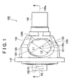
FIG 1 is a left side view of a differential case used in a differential gear unit according to a first embodiment of the invention; -
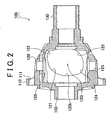
FIG 2 is a cross sectional view taken by a plane parallel with the plane of the paper ofFIG. 1 ; -
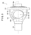
FIG. 3 is a right side view of the differential case used in the differential gear unit according to the first embodiment of the invention; -
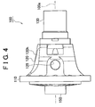
FIG 4 is a plan view of the differential case used in the differential gear unit according to the first embodiment of the invention; -
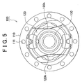
FIG 5 is a front view of the differential case used in the differential gear unit according to the first embodiment of the invention; -
FIG 6 is a rear view of the differential case used in the differential gear unit according to the first embodiment of the invention; -
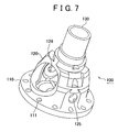
FIG 7 is a perspective view of the differential case used in the differential gear unit according to the first embodiment of the invention; -
FIG 8 is a perspective view of the differential case used in the differential gear unit according to the first embodiment of the invention; -
FIG. 9 is a perspective view of the differential case used in the differential gear unit according to the first embodiment of the invention; -
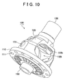
FIG. 10 is a perspective view of the differential case used in the differential gear unit according to the first embodiment of the invention; -
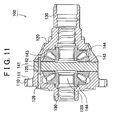
FIG 11 is a cross sectional view of the differential gear unit according to the first embodiment of the invention; -
FIG 12 is a left side view of a differential case used in a differential gear unit according to an alternative embodiment not forming part of the invention; -
FIG 13 is a first block diagram of a drive unit for a vehicle, to which the first embodiment of the invention is applied; -
FIG 14 is a second block diagram of the drive unit for a vehicle, to which the first embodiment of the invention is applied; and -
FIG 15 is a third block diagram of the drive unit for a vehicle, to which the first embodiment of the invention is applied. - In the following description and the accompanying drawings, the present invention will be described in more detail in terms of exemplary embodiments. In the following embodiments, the same reference numerals will be assigned to the same or corresponding elements, and the description thereof will be made only once.
-
FIG 1 is a left side view of a differential case used in a differential gear unit according to a first embodiment of the invention.FIG. 2 is a cross sectional view ofFIG. 1 .FIG 3 is a right side view of the differential case used in the differential gear unit according to the first embodiment of the invention. Referring toFIGS. 1 to 3 , adifferential case 120 used in adifferential gear unit 100 according to the first embodiment of the invention is in a box-shape and has aninternal space 120i. Aflange portion 110 and aprotruding portion 150 are provided at one end of thedifferential case 120, and anoutput portion 130 is provided at the other end. Each of theprotruding portion 150 and theoutput portion 130 has a cylindrical shape, and is communicated with theinternal space 120i. The outer diameter of thedifferential case 120 is decreased from theflange portion 110 to theoutput portion 130. - Elements constituting the
differential gear unit 100, for example, pinions which divide power, a pinion shaft which supports the pinions, and side gears which are meshed with the pinions are provided in theinternal space 120i. An opening 120h for inserting these elements into theinternal space 120i is formed in a side surface of thedifferential case 120. Namely, the opening 120h is formed in each of a right side surface and a left side surface. Theseopenings 120h are formed in a symmetrical pattern. - The opening 120h is in a rectangular shape having a round shape at each of the corner portions, that is, in a shape close to an ellipse. The shape of the opening 120h is asymmetrical with respect to a
rotational axis 100a of thedifferential case 120. A longer diagonal line of the opening 120h is referred to as L1, and a shorter diagonal line of the opening 120h is referred to as L2 (L2 is shorter than L1). In the first embodiment, theopening 120 has a rectangular shape having a round shape at each of the corner portions thereof. However, the corner portions are not necessarily rounded. - The
flange portion 110 is connected to a ring gear (not shown). The ring gear receives power from a drive pinion, and transmits the power to theflange portion 110. Thus, theflange portion 110 can be rotated in both the direction shown by an arrow R1 and the direction shown by an arrow R2.Multiple holes 111 are formed in theflange portion 110, and a bolt is inserted in each of theholes 111, whereby the ring gear is attached to theflange portion 110. - The cylindrical protruding
portion 150 is provided so as to be adjacent to theflange portion 110. A drive shaft is inserted in the protrudingportion 150. The protrudingportion 150 can be supported by a bearing in a differential carrier or a transmission case. The protrudingportion 150 is provided coaxially with theoutput portion 130. - The
opening 120h is defined by afirst corner portion 121, asecond corner portion 122, athird corner portion 123 and afourth corner portion 124. Each corner portion has a round shape or a curved surface shape in which the radius of the round shape continuously changes. Each of thefirst corner portion 121 and thethird corner portion 123 has a large curvature radius, that is, has a gentle curvature. Each of thesecond corner portion 122 and thefourth corner portion 124 has a small curvature radius, that is, has a sharp curvature. - Since the distance from a
center 120c of theopening 120h to each of thefirst corner portion 121 and thethird corner portion 123 is short, the strength of thedifferential case 120 at thefirst corner portion 121 and thethird corner portion 123 becomes higher. On the other hand, since the distance from thecenter 120c of the opening to each of thesecond corner portion 122 and thefourth corner portion 124 is long, the strength of thedifferential case 120 at thesecond corner portion 122 and thefourth corner portion 124 becomes lower. When each component is inserted in theinternal space 120i, the component is inserted through theopening 120h. When the size of the component is L1 or smaller, the component can be inserted in theinternal surface 120i through theopening 120h. - There is formed a
hole 125 for inserting the pinion shaft such that the pinion shaft penetrates thedifferential case 120. The direction in which thehole 125 extends is perpendicular to the direction in which therotational axis 100a extends. Also, ahole 126 for inserting a pin is formed in the direction perpendicular to the direction in which thehole 125 extends. -
FIG. 4 is a plan view of the differential case used in the differential gear unit according to the first embodiment of the invention. A bottom plan view is in the same shape as the plan view. Referring toFIG. 4 , thehole 125 is formed at a top portion of thedifferential case 120. Thehole 125 has a substantially circular shape. As shown in the plan view, although theopening 120h in an upper side portion inFIG 4 can be seen, the opening in a lower side portion cannot be seen. Based on this as well, it is understood that the shape of theopening 120h is asymmetrical with respect to therotational axis 100a. -
FIG 5 is a front view of thedifferential case 120 used in thedifferential gear unit 100 according to the first embodiment of the invention.FIG. 6 is a rear view of the differential case used in the differential gear unit according to the first embodiment of the invention. Referring toFIGS. 5 and6 , theflange portion 110 of thedifferential case 120 has a disc-shape, and holes 111 are formed so as to divide the periphery of theflange portion 110 into equal portions. Note that the number and arrangement of theholes 111 are not limited to those shown inFIGS. 5 and6 . Theholes 111 may be formed so as to divide the periphery of theflange portion 110 into unequal portions. - As shown in
FIG. 5 , theopening 120h is formed on each of the right and left sides of thedifferential case 120. Theoutput portion 130 is connected to a rear wheel via a propeller shaft. A drive shaft is inserted in theoutput portion 130, and the drive shaft and theoutput portion 130 can be rotated with a relative rotational difference. Also, another drive shaft is inserted in the protrudingportion 150. A side gear is connected to each of these drive shafts. - Each of
FIGS. 7 to 10 is a perspective view of the differential case used in the differential gear unit according to the first embodiment of the invention. Referring toFIGS. 7 to 10 , thedifferential case 120 includes the cylindrical protrudingportion 150; the disc-shapedflange portion 110 in which a driving force is input; and theoutput portion 130 which is provided at the end portion of thedifferential case 120, which is positioned opposite to the protrudingportion 150. Thedifferential case 120 defines theinternal space 120i communicated with the protrudingportion 150 and theoutput portion 130. Theopening 120h for permitting communication between the internal space and the outside is formed in the side surface of thedifferential case 120. Thehole 125 for inserting the pinion shaft is formed at a position different from the position of theopening 120h. -
FIG. 11 is a cross sectional view of the differential gear unit according to the first embodiment of the invention. Referring toFIG. 11 , apinion 143 which divides power; apinion shaft 141 which supports thepinion 143; a pin 142 which positions thepinion shaft 141; and paired side gears 144 meshed with thepinion 143 are provided in theinternal space 120i. Note that, inFIG. 11 , a constant-velocity joint is not provided in theside gear 144. However, an element of the constant-velocity joint may be integrally provided in theside gear 144. - The
side gear 144 is connected to the drive shaft, and an output from theside gear 144 is transmitted to a wheel. Theoutput portion 130 is connected to the propeller shaft. Note that thedifferential gear unit 100 in the embodiment is used as a front differential for a four-wheel drive vehicle without a center differential. - The
pinion shaft 141 is provided so as to penetrate theinternal space 120i. Thepinion 143 can be rotated about thepinion shaft 141. Since thepinion shaft 141 can be rotated along with thedifferential case 120 in the directions shown by the arrows R1 and R2 inFIG. 1 , thepinion 143 can also be rotated in the directions shown by the arrows R1 and R2. Namely, thepinion 143 can rotate on its axis and revolve around therotational axis 100a of thedifferential case 120. - The
pinion shaft 141 is positioned by the pin 142. Thepinion 143 and theside gear 144 slide over the inner surface of thedifferential case 120 which defines theinternal space 120i. Therefore, in the inner surface of thedifferential case 120, the abrasion resistance of the portion, over which thepinion 143 and theside gear 144 slide, can be increased by heat treatment or the like. - The
differential gear unit 100 according to the first embodiment of the invention divides the driving force input therein into the first output and the second output, and permits the difference between the first output and the second output. Thedifferential gear unit 100 includes thedifferential case 120 serving as a casing which defines theinternal space 120i and theopening 120h communicated with theinternal space 120i, and which can be rotated in the given direction (the direction shown by the arrow R1) and the direction opposite to the given direction (shown by the arrow R2). - The
differential case 120 includes theflange portion 110 as the input portion in which a driving force is input. Thedifferential case 120 is configured such that the fatigue life of thedifferential case 120 when a driving force is repeatedly input in theflange portion 110 in the direction shown by the arrow R1 is longer than the fatigue life of thedifferential case 120 when a driving force is repeatedly input in theflange portion 110 in the direction opposite to the direction shown by the arrow R1 (the direction shown by the arrow R2). - The direction shown by the arrow R1 is the rotational direction in which the vehicle runs forward. The
differential gear unit 100 further includes thepinion 143 serving as a dividing mechanism which is provided in theinternal space 120i and which divides a driving force into the first output and the second output; and thepinion shaft 141 serving as a support member which is provided so as to contact thedifferential case 120 and so as to support thepinion 143. Thepinion shaft 141 supports thepinion 143 such that thepinion 143 can rotate on its axis. Also, thepinion shaft 141 can make thepinion 143 revolve around therotational axis 100a of thedifferential case 120. - The
differential case 120 has thehole 125 as a support portion which permits contact with thepinion shaft 141. The fatigue life of thedifferential case 120 is measured by inputting a driving force in theflange portion 110 without rotating the support portion. Thedifferential case 120 includes theoutput portion 130 for outputting the driving force. The fatigue life of thedifferential case 120 is measured by inputting a driving force in theflange portion 110 without rotating theoutput portion 130. Namely, at least one of the fatigue life of the portion between theflange portion 110 and thehole 125 and the fatigue life of the portion between theflange portion 110 and theoutput portion 130 is long for rotation in a given direction and short for rotation in a direction opposite to the given direction. - The fatigue life of the
differential case 120 is adjusted by making the shape of theopening 120h asymmetrical with respect to therotational axis 100a. Also, theopening 120h is in a rectangular shape having a round shape at each of the corner portions, and the round shapes of the adjacent corner portions are different from each other. - In the
differential case 120 provided in thedifferential gear unit 100 according to the invention, the shape of theopening 120h is asymmetrical with respect to therotational axis 100a. Namely, in the differential gear unit including thedifferential case 120 in which theopening 120h is formed through which theside gear 144 and thepinion 143 can be provided the inside of thedifferential case 120, the shape of theopening 120h is formed such that the fatigue life when a driving force, which is applied in the forward rotational direction and which is equal to a driving force applied in the backward rotational direction, is repeatedly applied to the differential gear unit, is longer than the fatigue life when a driving force applied in the backward rotational direction is repeatedly applied to the differential gear unit. - More particularly, the
opening 120h is in the rectangular shape having a round shape at each of the corner portions thereof, and the round shapes of the corner portions, which are adjacent to each other in the rotational direction of thedifferential gear unit 100, are different from each other. It is thus possible to obtain the fatigue life necessary for the increased driving force while maintaining the assembly performance of a differential gear. Therefore, the size of thedifferential case 120 need not be changed. As a result, the moutability of thedifferential gear unit 100 is increased, and an increase in weight thereof can be suppressed. Also, the above-mentioned effects can be reliably obtained with a small design change by adjusting the round shape of the corner portion. - The corner portions will be described in detail. Generally, the life of the steel constituting the
differential case 120 for a tensile stress is rather short, and the life thereof for a compression stress is rather long. Accordingly, when the fatigue life of the portion where a tensile stress is generated in the frequently-used rotational direction (the rotational direction for forward running) is made longer, the fatigue life of the entire differential case is increased. In thefirst corner portion 121 and thethird corner portion 123, a tensile stress is generated when the vehicle runs forward, that is, when a driving force is supplied in the direction shown by the arrow R1. As a result, by increasing the curvature radius at this portion, the strength of thefirst corner portion 121 and thethird corner portion 123 is increased. On the other hand, the curvature radius is made smaller in thesecond corner portion 122 and thefourth corner portion 124 in which a compression stress is generated. Thus, the diagonal line L1 is made longer, and a space, in which the differential gear unit is inserted, is obtained. - In the
differential case 120, the tensile stress and the compression stress are generated between the portion in which a driving force is input and the portion which outputs the driving force. When the above-mentioned differential gear unit is used as a differential gear unit for a two-wheel drive vehicle, a driving force is input from theflange portion 110, and thehole 125 for holding thepinion shaft 141 supports the output driving force. As a result, the above-mentioned tensile stress and compression stress are generated between theflange portion 110 and thehole 125. The differential gear unit is designed such that the life of each of thefirst corner portion 121 and thethird corner portion 123, in which the tensile stress is generated, is made longer. - The torque required to break the
opening 120h by rotating theflange portion 110 of thedifferential case 120 is referred to as the braking torque. The fatigue life is evaluated by inputting 40% of the braking torque in theflange portion 110, and fixing a predetermined portion of thedifferential case 120, based on the number of times the torque is input until theopening 120h breaks. - When the
output portion 130 is connected to the rear propeller shaft, a driving force is input in theflange portion 110, and output from theoutput portion 130. In this case, the life of the portion, where a tensile stress is generated between theflange portion 110 and theoutput portion 130, is made long. - With the thus configured differential gear unit according to the invention, increases in weight and size thereof can be minimized, and the life thereof can be made longer.
-
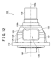
FIG. 12 is a left side view of a differential case used in a differential gear unit according to an alternative embodiment not forming part of the invention. Referring toFIG 12 , in the differential gear unit according to the alternative embodiment of the invention, the shape of theopening 120h is symmetrical with respect to therotational axis 100a. However, the differential gear unit according to the alternative embodiment is different from the differential gear unit according to the first differential gear unit in that induction heat treatment is performed on thefirst corner portion 121 and the third corner,portion 123 in order to partially increase the strength in the alternative embodiment. As the heat treatment for thefirst corner portion 121 and thethird corner portion 123, various treatments for increasing the metal life, for example, induction hardening and carburizing treatment can be performed. Also, physical treatments, for example, shot blasting and shot peening, may be performed on thefirst corner portion 121 and thethird corner portion 123. Namely, in the differential case used in the differential gear unit according to the second embodiment of the invention, the fatigue life of the differential case is adjusted by performing heat treatment on the predetermined portion of the differential case. - As a modified example, the following example can be employed. In the differential case in the differential gear unit according to the first embodiment in which the
opening 120h of the differential case is asymmetrical with respect to therotational axis 100a, the heat treatment or the physical treatment described in the second embodiment may be performed on thefirst corner portion 121 and thethird corner portion 123. The fatigue life of the differential gear unit can be further increased by reducing a tensile stress by adjusting the shape, and by increasing the strength by performing the heat treatment or the physical treatment. - In the thus configured differential case according to the alternative embodiment, the same effects as the differential case according to the first embodiment can be obtained.
- Next, various cases will be described where the differential gear unit according to the first or second embodiment of the invention is applied to a drive unit for an automobile.
FIG 13 is a first block diagram for describing a drive unit for an automobile to which the differential gear unit according to the first embodiment is applied. Referring toFIG 13 , the drive unit for an automobile includes anengine 200 which generates a driving force; atransmission 300 which receives the driving force from theengine 200 and which changes a rotational speed and rotational torque; atransfer 400 which serves as a sub-transmission which receives an output from thetransmission 300 and which further changes the speed thereof; and a front differential 100x and a rear differential 100y which are connected to thetransfer 400. The differential gear unit according to the first embodiment can be applied to one of the front differential 100x and the rear differential 100y.FIG 14 shows part time four-wheel drive vehicle in which there is no center differential. In such an automobile, the differential gear unit according to the first or the second embodiment can be used. -
FIG 14 is a second block diagram for describing the drive unit for an automobile to which the first embodiment of the invention is applied. InFIG 14 , a center differential 100z for distributing power of thetransmission 300 is provided; and an output from the center differential 100z is transmitted to the front differential 100x and the rear differential 100y. The differential gear unit according to the first or the second embodiment can be applied to at least one of the front differential 100x, the center differential 100z and the rear differential 100y. A transfer serving as a sub-transmission may be provided between the center differential 100z and thetransmission 300. The drive unit inFIG 14 is a drive unit for the full time four-wheel drive vehicle. The differential gear unit according to the invention can be provided in such a full time four-wheel drive vehicle. -
FIG 15 is a third block diagram for describing the drive unit for an automobile to which the differential gear unit according to the first embodiment of the invention is applied. Referring toFIG. 15 , the drive unit for an automobile to which the differential gear unit according to the first embodiment is applied is different from the drive unit for an automobile shown in the second block diagram in that the center differential is omitted in the drive unit for an automobile inFIG 15 . Namely, the output from thetransmission 300 is distributed to the front differential 100x and the rear differential 100y without using the center differential. The differential gear unit according to the first embodiment can be applied to at least one of the front differential 100x and the rear differential 100y. A biscous coupling for absorbing a rotational difference between the front differential 100x and the rear differential 100y may be provided. As described so far, the differential gear unit according to the invention can be applied to a simplified four-wheel drive vehicle. - So far, the differential gear unit according to the first embodiment of the invention and the vehicle provided with the drive unit including the differential gear unit have been described. Meanwhile, the differential gear unit and the drive unit can be realized in various modified embodiments. First, the differential gear unit can be used not only as the differential gear unit for the front wheel and the rear wheel of an automobile but also as the center differential for a four-wheel drive vehicle or a six-wheel drive vehicle. Also, the differential gear unit can be applied not only to an automobile using a gasoline engine as a power source but also to a hybrid vehicle using gasoline and electric power as power, or a fuel cell vehicle.
- So far, description has been made concerning the case where the invention is applied to a differential gear unit for a vehicle. However, a differential gear unit to which the invention is applied is not limited to a differential gear unit for a vehicle. The invention can be applied to any types of differential gear unit as long as the frequency of using one rotational direction and the frequency of using another rotational direction are different in the differential gear unit.
- The invention can be applied to a differential gear unit for an automobile and a differential gear unit used in other fields.
Claims (6)
- A differential gear unit (100) which divides an input driving force into a first output and second output and permits a difference between a rotational speed of the first output and a rotational speed of the second output, and which includes a casing (120) that defines an internal space (120i) and an opening (120h) communicated with the internal space (120i), the opening (120h) being in a basically elliptical shape having a round shape at each of corner portions (121, 122, 123, 124), the round shapes of the adjacent corner portions (121, 122, 123, 124) are different from each other, the casing (120) being rotatable in a given rotational direction (R1) and in a rotational direction (R2) opposite to the given rotational direction (R1),
wherein rotation in the given direction (R1) is rotation around a rotational axis (100a) of the differential gear casing (120), the casing (120) including an input portion (110) in which the driving force is input, and
wherein a dividing mechanism which is provided in the internal space (120i) and which divides the driving force into the first output and the second output; and a support member which is provided so as to contact the casing (120) and so as to support the dividing mechanism are further provided, the dividing mechanism includes a pinion (143), and the support member includes a pinion shaft (141) which supports the pinion (143) such that the pinion (143) can rotate on its axis and which makes the pinion (143) revolve around a center of the casing (120),
characterized in that
the casing (120) is configured such that fatigue life of the casing (120) when the driving force is repeatedly input in the input portion (110) in the given rotational direction (R1) is longer than fatigue life of the casing (120) when the driving force is repeatedly input in the input portion (110) in the rotational direction opposite to the given rotational direction (R2),
the fatigue life of the casing (120) is adjusted by making a shape of the opening (120h) asymmetrical with respect to said rotational axis (100a) of the casing (120), wherein
a curvature radius of the round shape of the corner portion (121, 123) of the opening (120h), at which corner portion a tensile stress is generated when the driving force is input in the given rotational direction (R1), is larger than a curvature radius of the round shape of the corner portion (122, 124) of the opening (120h), at which corner portion a compression stress is generated when the driving force is input in the given rotational direction (R1),
and in that the fatigue life of the casing (120) is adjusted by performing heat treatment on the corner portion (121, 123) of the opening (120h) of the casing (120), where a tensile stress is generated when the driving force is input in the given rotational direction (R1). - The differential gear unit according to claim 1, characterized in that
the casing (120) includes a support portion (125) which contacts the support member, and the fatigue life is measured by inputting the driving force in the input portion (110) without rotating the support portion (125). - The differential gear unit according to claim 2, characterized in that
the casing (120) includes an output portion (130) which is provided at a position that is different from a position of the support portion (125), and the fatigue life is measured by inputting the driving force in the input portion (110) without rotating the output portion (130). - The differential gear unit according to claim 1, characterized in that
the heat treatment includes at least one of induction hardening and carburizing treatment. - The differential gear unit according to any one of claims 1 through 4, characterized in that
the fatigue life of the casing (120) is adjusted by performing physical treatment on the corner portion (121, 123) of the opening (120h) of the casing (120), where a tensile stress is generated when the driving force is input in the given rotational direction (R1). - The differential gear unit according to claim 5, characterized in that
the physical treatment includes at least one of shot blasting and shot peening.
Applications Claiming Priority (2)
| Application Number | Priority Date | Filing Date | Title |
|---|---|---|---|
| JP2004024091A JP4686982B2 (en) | 2004-01-30 | 2004-01-30 | Differential |
| PCT/IB2005/000195 WO2005080822A2 (en) | 2004-01-30 | 2005-01-27 | Differential gear unit |
Publications (2)
| Publication Number | Publication Date |
|---|---|
| EP1709345A2 EP1709345A2 (en) | 2006-10-11 |
| EP1709345B1 true EP1709345B1 (en) | 2010-10-06 |
Family
ID=34879121
Family Applications (1)
| Application Number | Title | Priority Date | Filing Date |
|---|---|---|---|
| EP05702352A Expired - Fee Related EP1709345B1 (en) | 2004-01-30 | 2005-01-27 | Differential gear unit |
Country Status (7)
| Country | Link |
|---|---|
| US (1) | US7827882B2 (en) |
| EP (1) | EP1709345B1 (en) |
| JP (1) | JP4686982B2 (en) |
| KR (1) | KR100817586B1 (en) |
| CN (1) | CN1938532A (en) |
| DE (1) | DE602005023956D1 (en) |
| WO (1) | WO2005080822A2 (en) |
Families Citing this family (13)
| Publication number | Priority date | Publication date | Assignee | Title |
|---|---|---|---|---|
| JP4706431B2 (en) * | 2005-10-21 | 2011-06-22 | 株式会社ジェイテクト | Vehicle differential, vehicle hybrid differential, and vehicle differential case |
| JP2008008460A (en) | 2006-06-30 | 2008-01-17 | Gkn ドライブライン トルクテクノロジー株式会社 | Differential device |
| JP5309045B2 (en) * | 2010-02-02 | 2013-10-09 | ジヤトコ株式会社 | Differential gear case and processing method thereof |
| JP6127904B2 (en) * | 2013-10-23 | 2017-05-17 | スズキ株式会社 | Transmission case |
| JP6217023B2 (en) * | 2013-12-27 | 2017-10-25 | 武蔵精密工業株式会社 | Differential device and manufacturing method thereof |
| CN104088984B (en) * | 2014-07-24 | 2016-09-14 | 江苏汤臣汽车零部件有限公司 | A kind of light-weighted semi-trailer differential carrier |
| CN104088990B (en) * | 2014-07-24 | 2016-07-13 | 江苏汤臣汽车零部件有限公司 | A kind of lightweight heavy truck differential carrier |
| US9388893B1 (en) * | 2015-03-06 | 2016-07-12 | Gkn Driveline North America, Inc. | Vehicle differential housing with protuberances |
| JP6501584B2 (en) * | 2015-03-30 | 2019-04-17 | 武蔵精密工業株式会社 | Transmission |
| WO2016207974A1 (en) * | 2015-06-23 | 2016-12-29 | Gkn ドライブライン ジャパン株式会社 | Differential case |
| JP6876592B2 (en) * | 2017-10-30 | 2021-05-26 | 武蔵精密工業株式会社 | Differential device |
| JP6847874B2 (en) | 2018-01-18 | 2021-03-24 | 武蔵精密工業株式会社 | Differential device |
| US11384830B2 (en) | 2019-08-06 | 2022-07-12 | Toyota Motor Engineering & Manufacturing North America, Inc. | Window design for a differential housing |
Family Cites Families (23)
| Publication number | Priority date | Publication date | Assignee | Title |
|---|---|---|---|---|
| US3901103A (en) * | 1974-03-28 | 1975-08-26 | Gen Motors Corp | Differential gear mechanism |
| US3955443A (en) * | 1975-01-30 | 1976-05-11 | Jose Luis Estrada | Differential gear mechanism with asymmetric pinion gears |
| US4038189A (en) * | 1976-01-16 | 1977-07-26 | The United States Of America As Represented By The Secretary Of The Air Force | Fluid dual filter |
| DE2639150C2 (en) * | 1976-08-31 | 1983-03-10 | Daimler-Benz Ag, 7000 Stuttgart | Storage of a differential housing of a differential gear in an axle housing |
| US4154065A (en) * | 1977-08-05 | 1979-05-15 | Neapco, Inc. | Universal joint pivot assembly |
| JPS58144141A (en) | 1982-02-23 | 1983-08-27 | 旭化成株式会社 | Parallel type multilayer structural spun yarn |
| JPS58144141U (en) * | 1982-03-23 | 1983-09-28 | 三菱自動車工業株式会社 | 4-pinion differential with integrated differential case |
| GB8319788D0 (en) * | 1983-07-22 | 1983-08-24 | Vickers Shipbuilding & Eng | Induction hardening of gear teeth |
| US4625585A (en) * | 1985-01-09 | 1986-12-02 | Tractech, Inc. | Torque-proportioning differential with sectional housing |
| SE459034B (en) * | 1988-04-28 | 1989-05-29 | Saab Scania Ab | DIFFERENTIAL WITH FOUR DIFFERENTIAL DRIVES |
| JPH02138554A (en) * | 1988-11-16 | 1990-05-28 | Nissan Motor Co Ltd | Highly strenghtened gear |
| SE462929B (en) * | 1989-09-13 | 1990-09-17 | Saab Scania Ab | DIFFERENTIAL |
| JPH0444353U (en) * | 1990-08-15 | 1992-04-15 | ||
| JP2921112B2 (en) * | 1990-11-30 | 1999-07-19 | 日本精工株式会社 | Rolling bearing |
| JP3075594B2 (en) | 1991-06-28 | 2000-08-14 | 蛇の目ミシン工業株式会社 | Overlock width adjustment device for sewing machine |
| JPH053974U (en) * | 1991-07-03 | 1993-01-22 | 三菱自動車工業株式会社 | Auxiliary device for differential case fatigue testing |
| JPH09229162A (en) * | 1996-02-26 | 1997-09-02 | Yanagawa Seiki Kk | Differential |
| US5951431A (en) * | 1997-05-06 | 1999-09-14 | American Axle & Manufacturing, Inc. | Differential unit with optimized assembly window geometry |
| US6139462A (en) * | 1998-08-27 | 2000-10-31 | American Axle & Manufacturing, Inc. | Differential with laser hardened case |
| JP4316196B2 (en) | 2001-07-24 | 2009-08-19 | Gkn ドライブライン トルクテクノロジー株式会社 | Differential limiter |
| DE10141995A1 (en) * | 2001-08-28 | 2003-04-03 | Johann Hay Gmbh & Co Kg Automo | differential case |
| CN1531635A (en) * | 2002-08-02 | 2004-09-22 | 株式会社音户工作所 | Differiential device for vehicle |
| US7320659B2 (en) * | 2005-04-29 | 2008-01-22 | American Axle & Manufacturing, Inc. | Differential assembly with semi-elliptical assembly window |
-
2004
- 2004-01-30 JP JP2004024091A patent/JP4686982B2/en not_active Expired - Fee Related
-
2005
- 2005-01-27 DE DE602005023956T patent/DE602005023956D1/en active Active
- 2005-01-27 US US10/586,607 patent/US7827882B2/en active Active
- 2005-01-27 KR KR1020067015366A patent/KR100817586B1/en not_active IP Right Cessation
- 2005-01-27 CN CNA2005800035353A patent/CN1938532A/en active Pending
- 2005-01-27 WO PCT/IB2005/000195 patent/WO2005080822A2/en not_active Application Discontinuation
- 2005-01-27 EP EP05702352A patent/EP1709345B1/en not_active Expired - Fee Related
Also Published As
| Publication number | Publication date |
|---|---|
| KR100817586B1 (en) | 2008-03-31 |
| JP2005214347A (en) | 2005-08-11 |
| KR20070006730A (en) | 2007-01-11 |
| JP4686982B2 (en) | 2011-05-25 |
| EP1709345A2 (en) | 2006-10-11 |
| US20080229878A1 (en) | 2008-09-25 |
| WO2005080822A2 (en) | 2005-09-01 |
| DE602005023956D1 (en) | 2010-11-18 |
| US7827882B2 (en) | 2010-11-09 |
| WO2005080822A3 (en) | 2006-10-26 |
| CN1938532A (en) | 2007-03-28 |
Similar Documents
| Publication | Publication Date | Title |
|---|---|---|
| EP1709345B1 (en) | Differential gear unit | |
| JP3805890B2 (en) | Differential unit with optimized assembly window geometry | |
| EP2450598B1 (en) | Helical gear differential | |
| EP1777438B1 (en) | Vehicle differential gear device, vehicle combined differential gear device and vehicle differential case | |
| EP1734287B1 (en) | Differential gearing for vehicle | |
| US8113979B2 (en) | Four pinion differential with cross pin retention unit and related method | |
| EP2110582B1 (en) | Differential device for vehicle | |
| US7951037B2 (en) | Four pinion differential with cross pin retention unit and related method | |
| EP1717486B1 (en) | Differential assembly with semi-elliptical assembly window | |
| CN101821532A (en) | Have the load-bearing component of lightweight and the differential gear mechanism of viscous clutch | |
| US7658692B2 (en) | Double differential assembly for a motor vehicle driven by a plurality of axles | |
| US6726591B2 (en) | Four-wheel drive system for vehicles | |
| JP4784444B2 (en) | Vehicle differential | |
| US8870701B2 (en) | Double differential device for a vehicle | |
| JP5167876B2 (en) | Differential case and vehicle differential equipped with the same | |
| US10865852B2 (en) | Powertrain with cycloidal mechanism having reinforced contact surfaces | |
| JP3071694U (en) | Vehicle differential | |
| JP3648871B2 (en) | Power transmission device for four-wheel drive vehicles | |
| CN114393377A (en) | New energy automobile speed reducer and differential assembling method for grinding main reduction gear | |
| JP2018071563A (en) | Differential device for vehicle | |
| JP2017101774A (en) | Differential gear | |
| JP2010138968A (en) | Differential gear for vehicle | |
| MXPA98003411A (en) | Differential unit with optimized assembly window geometry |
Legal Events
| Date | Code | Title | Description |
|---|---|---|---|
| PUAI | Public reference made under article 153(3) epc to a published international application that has entered the european phase |
Free format text: ORIGINAL CODE: 0009012 |
|
| 17P | Request for examination filed |
Effective date: 20060707 |
|
| AK | Designated contracting states |
Kind code of ref document: A2 Designated state(s): AT BE BG CH CY CZ DE DK EE ES FI FR GB GR HU IE IS IT LI LT LU MC NL PL PT RO SE SI SK TR |
|
| AX | Request for extension of the european patent |
Extension state: AL BA HR LV MK YU |
|
| PUAK | Availability of information related to the publication of the international search report |
Free format text: ORIGINAL CODE: 0009015 |
|
| DAX | Request for extension of the european patent (deleted) | ||
| RBV | Designated contracting states (corrected) |
Designated state(s): DE FR |
|
| 17Q | First examination report despatched |
Effective date: 20070510 |
|
| GRAP | Despatch of communication of intention to grant a patent |
Free format text: ORIGINAL CODE: EPIDOSNIGR1 |
|
| GRAS | Grant fee paid |
Free format text: ORIGINAL CODE: EPIDOSNIGR3 |
|
| GRAA | (expected) grant |
Free format text: ORIGINAL CODE: 0009210 |
|
| AK | Designated contracting states |
Kind code of ref document: B1 Designated state(s): DE FR |
|
| REF | Corresponds to: |
Ref document number: 602005023956 Country of ref document: DE Date of ref document: 20101118 Kind code of ref document: P |
|
| PLBE | No opposition filed within time limit |
Free format text: ORIGINAL CODE: 0009261 |
|
| STAA | Information on the status of an ep patent application or granted ep patent |
Free format text: STATUS: NO OPPOSITION FILED WITHIN TIME LIMIT |
|
| 26N | No opposition filed |
Effective date: 20110707 |
|
| REG | Reference to a national code |
Ref country code: DE Ref legal event code: R097 Ref document number: 602005023956 Country of ref document: DE Effective date: 20110707 |
|
| REG | Reference to a national code |
Ref country code: DE Ref legal event code: R084 Ref document number: 602005023956 Country of ref document: DE Effective date: 20121015 |
|
| REG | Reference to a national code |
Ref country code: FR Ref legal event code: PLFP Year of fee payment: 12 |
|
| PGFP | Annual fee paid to national office [announced via postgrant information from national office to epo] |
Ref country code: FR Payment date: 20151208 Year of fee payment: 12 |
|
| REG | Reference to a national code |
Ref country code: FR Ref legal event code: ST Effective date: 20170929 |
|
| PG25 | Lapsed in a contracting state [announced via postgrant information from national office to epo] |
Ref country code: FR Free format text: LAPSE BECAUSE OF NON-PAYMENT OF DUE FEES Effective date: 20170131 |
|
| PGFP | Annual fee paid to national office [announced via postgrant information from national office to epo] |
Ref country code: DE Payment date: 20211130 Year of fee payment: 18 |
|
| REG | Reference to a national code |
Ref country code: DE Ref legal event code: R119 Ref document number: 602005023956 Country of ref document: DE |
|
| PG25 | Lapsed in a contracting state [announced via postgrant information from national office to epo] |
Ref country code: DE Free format text: LAPSE BECAUSE OF NON-PAYMENT OF DUE FEES Effective date: 20230801 |