EP1709319B1 - Fuel injector with direct needle control - Google Patents
Fuel injector with direct needle control Download PDFInfo
- Publication number
- EP1709319B1 EP1709319B1 EP04802766A EP04802766A EP1709319B1 EP 1709319 B1 EP1709319 B1 EP 1709319B1 EP 04802766 A EP04802766 A EP 04802766A EP 04802766 A EP04802766 A EP 04802766A EP 1709319 B1 EP1709319 B1 EP 1709319B1
- Authority
- EP
- European Patent Office
- Prior art keywords
- booster
- valve member
- injection valve
- pressure
- region
- Prior art date
- Legal status (The legal status is an assumption and is not a legal conclusion. Google has not performed a legal analysis and makes no representation as to the accuracy of the status listed.)
- Expired - Fee Related
Links
- 239000000446 fuel Substances 0.000 title claims description 58
- 238000002347 injection Methods 0.000 claims description 103
- 239000007924 injection Substances 0.000 claims description 103
- 238000002485 combustion reaction Methods 0.000 claims description 12
- 230000007704 transition Effects 0.000 claims description 7
- 238000007789 sealing Methods 0.000 description 9
- 230000007423 decrease Effects 0.000 description 4
- 239000013078 crystal Substances 0.000 description 3
- 238000003860 storage Methods 0.000 description 3
- 230000015572 biosynthetic process Effects 0.000 description 1
- 238000010276 construction Methods 0.000 description 1
- 239000002828 fuel tank Substances 0.000 description 1
- 238000004519 manufacturing process Methods 0.000 description 1
- 238000000034 method Methods 0.000 description 1
- 238000011144 upstream manufacturing Methods 0.000 description 1
- 238000003466 welding Methods 0.000 description 1
Images
Classifications
-
- F—MECHANICAL ENGINEERING; LIGHTING; HEATING; WEAPONS; BLASTING
- F02—COMBUSTION ENGINES; HOT-GAS OR COMBUSTION-PRODUCT ENGINE PLANTS
- F02M—SUPPLYING COMBUSTION ENGINES IN GENERAL WITH COMBUSTIBLE MIXTURES OR CONSTITUENTS THEREOF
- F02M51/00—Fuel-injection apparatus characterised by being operated electrically
- F02M51/06—Injectors peculiar thereto with means directly operating the valve needle
- F02M51/0603—Injectors peculiar thereto with means directly operating the valve needle using piezoelectric or magnetostrictive operating means
-
- F—MECHANICAL ENGINEERING; LIGHTING; HEATING; WEAPONS; BLASTING
- F02—COMBUSTION ENGINES; HOT-GAS OR COMBUSTION-PRODUCT ENGINE PLANTS
- F02M—SUPPLYING COMBUSTION ENGINES IN GENERAL WITH COMBUSTIBLE MIXTURES OR CONSTITUENTS THEREOF
- F02M2200/00—Details of fuel-injection apparatus, not otherwise provided for
- F02M2200/21—Fuel-injection apparatus with piezoelectric or magnetostrictive elements
-
- F—MECHANICAL ENGINEERING; LIGHTING; HEATING; WEAPONS; BLASTING
- F02—COMBUSTION ENGINES; HOT-GAS OR COMBUSTION-PRODUCT ENGINE PLANTS
- F02M—SUPPLYING COMBUSTION ENGINES IN GENERAL WITH COMBUSTIBLE MIXTURES OR CONSTITUENTS THEREOF
- F02M2200/00—Details of fuel-injection apparatus, not otherwise provided for
- F02M2200/70—Linkage between actuator and actuated element, e.g. between piezoelectric actuator and needle valve or pump plunger
- F02M2200/703—Linkage between actuator and actuated element, e.g. between piezoelectric actuator and needle valve or pump plunger hydraulic
-
- F—MECHANICAL ENGINEERING; LIGHTING; HEATING; WEAPONS; BLASTING
- F02—COMBUSTION ENGINES; HOT-GAS OR COMBUSTION-PRODUCT ENGINE PLANTS
- F02M—SUPPLYING COMBUSTION ENGINES IN GENERAL WITH COMBUSTIBLE MIXTURES OR CONSTITUENTS THEREOF
- F02M61/00—Fuel-injectors not provided for in groups F02M39/00 - F02M57/00 or F02M67/00
- F02M61/04—Fuel-injectors not provided for in groups F02M39/00 - F02M57/00 or F02M67/00 having valves, e.g. having a plurality of valves in series
- F02M61/10—Other injectors with elongated valve bodies, i.e. of needle-valve type
- F02M61/12—Other injectors with elongated valve bodies, i.e. of needle-valve type characterised by the provision of guiding or centring means for valve bodies
Definitions
- the injection pressure is provided via a high-pressure accumulator. Due to the large amount of fuel in the high-pressure accumulator compared to the injection quantity, pressure fluctuations during the injection process are avoided.
- the operation of the fuel injectors is carried out hydraulically with the fuel provided via the high-pressure accumulator.
- Fuel injectors as used in the prior art for high-pressure storage systems, z. B. from Mollenhauer, Manual Diesel Engines, Second Edition, Springer-Verlag, Berlin, 2002 known.
- both the opening and the closing operation is hydraulically controlled.
- a control chamber in which fuel is under injection pressure closed by a control valve.
- the fuel pressure acts on the rear side of a control piston, which acts into the control chamber, and on a pressure shoulder on an injection valve closing the injection openings.
- the hydraulic force on the back of the control piston of the hydraulic force acting on the pressure shoulder opposite. Due to the larger area on the control piston, the nozzle remains closed.
- the control valve opens the control chamber, the pressure in the control chamber is reduced and the hydraulic force on the pressure shoulder is greater than the pressure force acting on the back of the control piston. This causes the injection valve member to open.
- a fuel injector in which a pressure booster connected to a piezo actuator acts on an injection valve member via a booster chamber.
- the booster chamber is delimited by a pot-shaped sleeve, the fuel passing via the sleeve via a bypass to a pressure chamber located upstream of the injection openings.
- the cup-shaped sleeve of the pressure booster and the injection valve member is received in guides, so that the booster chamber is hydraulically sealed by the guides.
- the fuel injector designed according to the invention provides a fuel injector for high-pressure storage systems with a compact construction.
- an actuator of the fuel injector acts directly on a pressure booster designed as a booster piston.
- the actuator is z.
- As a piezoelectric actuator an electromagnet or a hydraulic / mechanical actuator.
- the actuator acts directly on an upper end face of the booster piston.
- a lower end face of the pressure booster forms one side of a booster chamber, and an end face of a stepped injection valve member bounds the booster chamber on the opposite side.
- a shoulder is formed in the interpreter room, so that the interpreter room tapers from a large to a smaller diameter.
- the larger diameter of the booster chamber faces the pressure translator of the same diameter, while the region of the small diameter booster chamber faces the injection valve member.
- the injection valve member is stepped in a translator area, a guide area and an original area. To open injection openings, the injection valve member moves in the direction of the pressure booster. In this case, the end face of the compiler area of the injection valve member moves into the interrupter space.
- the compiler area of the injection valve member is surrounded by a spring space in which a spring element is accommodated.
- the spring element is preferably designed as a spiral spring.
- the spring element On one side, the spring element is supported on a ring, which rests on an extension formed between the compiler area and the guide area of the injection valve member.
- the spring element On the other hand, the spring element is supported against an end face of a ring surrounding the compiler portion of the injection valve member sleeve.
- the sleeve is provided with a biting edge.
- the fuel used for the operation of the internal combustion engine flows from a high-pressure accumulator into an annular space surrounding the actuator. About absorbed in the injector bypasses the fuel flows from the annulus in the spring chamber. About guide leakage between the compiler area of the injection valve member and the sleeve fuel enters the interrupter space.
- the guide region of the injection valve member is provided with at least one bevel, so that the fuel between the Bevel and the needle guide flows in a surrounding the nozzle needle portion of the injection valve member annular pressure chamber.
- the formation of a bevel in the guide region of the injection valve member, along which the fuel can flow, ensures that system pressure prevails in the pressure chamber.
- the system pressure is preferably in the range of 150 to 2000 bar.
- the piezoelectric actuator When using a piezoelectric actuator for controlling the fuel injector, the piezoelectric actuator is energized to close the injection openings. When energized, the piezocrystals in the piezo actuator expand and the piezo actuator lengthens. The elongation of the piezoelectric actuator causes a force on the upper end face of the pressure booster. As a result, the pressure booster moves in the direction of the injection openings, thus reducing the size of the booster chamber arranged on the underside of the pressure booster. Due to the decrease in volume of the interpreter room, the pressure in the interpreter room increases. As a result, a larger hydraulic force acts on the end face of the translator part of the injection valve member.
- the injection valve member Due to the hydraulic force acting on the end face of the translator part of the injection valve member and acting on the extension between the compiler area and the guide portion of the injection valve member spring force, the injection valve member is placed on a combustion chamber facing the sealing edge of the pressure chamber. As a result, the at least one injection opening is closed in the combustion chamber.
- the piezoelectric actuator is energized, causing the piezoelectric crystals expand and the piezoelectric actuator lengthened.
- the piezoelectric actuator acts on the upper end face of the pressure booster, whereby it moves in the direction of the injection openings.
- the volume of the interpreter room is reduced, and at the same time, the pressure in the interpreter room increases.
- the force acting on the end face of the compiler portion of the injection valve member hydraulic force increases.
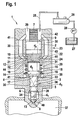
- the single FIGURE shows a fuel injector designed according to the invention.
- FIG. 1 an inventively designed fuel injector is shown.
- the injection valve member 3 is preferably divided into a translator area 4, a guide area 5 and a nozzle needle area 6.
- the diameter d 2 of the translator area 4 of the injection valve member 3 is greater than the one diameter d 3 of the guide portion 5 of the injection valve member 3.
- the diameter d 1 of the nozzle needle portion 6 is preferably smaller than the diameter d 3 of the guide portion 5 of the injection valve member.
- the control of the fuel injector 1 is preferably carried out by means of a piezoelectric actuator 7.
- the control can also be effected by an electromagnet or a hydraulic / mechanical actuator.
- the piezoelectric actuator 7 For closing at least one injection opening 8, the piezoelectric actuator 7 is energized. By energizing the piezocrystals expand and the piezoelectric actuator 7 lengthens. The piezoelectric actuator 7 acts directly on a piezoelectric actuator 7 facing upper end face 9 of the pressure booster 2. As a result, designed as a piston pressure booster 2 is moved in the direction of at least one injection port 8. With a lower end face 10 of the pressure booster 2 limits a booster chamber 11. By the movement of the pressure booster 2 in the direction of the at least one injection port 8, the volume of the booster chamber 11 is reduced. As a result, the pressure in the booster chamber 11 increases.
- At the lower end face 10 of the booster chamber 11 opposite side of the booster chamber 11 is bounded by an end face 12 of the booster section 4 of the injection valve member 3.
- the injection valve member 3 By acting on the end face 12 of the translator portion 4 of the injection valve member 3 hydraulic force the injection valve member 3 is placed on a above the at least one injection port 8 arranged sealing edge 13. As a result, the at least one of the injection opening 8 is closed.
- a spring force which is generated by a spring element 15 received in a spring chamber 14, supports the hydraulic force acting on the end face 12 of the booster region 4 of the injection valve member 3 when the injection valve member 3 is closed.
- the spring element 15 used is preferably a helical spring.
- the spring element 15 rests with one side preferably on a ring 16, which in turn rests on a step 18 formed by an extension 17 between the compiler area 4 and the guide area 5. On the other side, the spring element 15 is preferably supported against an end face 20 of the sleeve 19.
- a biting edge 21 is formed at the end face 20 opposite side of the sleeve 19, a biting edge 21 is formed. Due to the force exerted by the spring element 15 on the end face 20 of the sleeve 19 spring force the biting edge 21 of the sleeve 19 is pressed against a shoulder 22 in the injector 23. This results in a liquid-tight and thus pressure-tight connection between the shoulder 22 of the injector housing 23 and the sleeve 19.
- the inside 24 of the sleeve 19 serves as a guide for the translator section 4 of the injection valve member 3 and at the same time as a lateral boundary and seal of the translator chamber eleventh
- the fuel injector 1 is connected via a feed line 25 to a high pressure accumulator 26.
- the fuel passes from a fuel reservoir 27 via a high pressure pump 28.
- the system pressure of 150 to 2000 bar is provided.
- the fuel flows via the feed line 25 into an annular space 29 surrounding the piezoelectric actuator 7.
- the fuel flows via at least one of the annular space 29 Bypass 30 in the spring chamber 14.
- an annular gap 32 is formed between the outer side 31 of the sleeve 19 and the wall of the injector 23.
- the fuel passes along a bevel 33 in the guide region 5 of the objection valve member 3 in a pressure chamber 34 surrounding the nozzle needle portion 6 of the injection valve member 3.
- a bevel 33 in the guide portion 5 of the injection valve member 3 is a bypass between the guide portion 5 of the injection valve member 3 and a needle guide 35 formed in the nozzle part 36 of the injector 23.
- connection of the spring chamber 14 with the annular space 29 via the at least one bypass 30 and the connection of the annular space 29 with the high-pressure accumulator 26 via the supply line 25 prevail both in the annular space 29 as also in the spring chamber 14 and in the pressure chamber 34 system pressure, which is preferably in the range of 150 to 2000 bar.
- the pressure in the booster chamber 11 changes.
- the pressure in the booster chamber 11 is preferably higher than the system pressure.
- the pressure is preferably lower than the system pressure. Therefore, a pressure-tight connection between the sleeve 19 and the shoulder 22 of the injector is required.
- the current supply required for closing the piezoelectric actuator 7 is terminated.
- the piezocrystals in the piezoactuator 7 contract and the piezoactuator 7 contracts.
- Due to the force acting on the lower end face 10 of the pressure booster 2 hydraulic force of the pressure booster 2 is moved in the direction of the piezoelectric actuator 7.
- the volume of the booster chamber 11 increases, which leads to a decrease in the pressure in the booster chamber 11, compared with the pressure prevailing in the spring chamber 14 system pressure.
- the hydraulic force acting on the end face 12 of the translator area 4 of the injection valve member 3 decreases.
- first pressure stage 38 acts on a at the extension 17 between the compiler area 4 and the guide portion 5 of the injection valve member 3 formed first pressure stage 38, formed on a formed between the guide portion 5 and the nozzle needle portion 6 second pressure stage 39 and on the needle tip of the injection valve member 3 directly formed above the sealing edge 13 third pressure stage 40 a constant hydraulic force, which is directed against the hydraulic force on the end face 12 of the compiler area 4 of the injection valve member 3 opposite.
- the hydraulic force on the first pressure stage 38, the second pressure stage 39 and the third pressure stage 40 is constant, because the spring chamber 14 and the pressure chamber 34 constantly with system pressure are charged.
- a safe operating behavior of the fuel injector 1 is achieved in that the diameter d 4 of the pressure booster 2 is greater than the diameter d 2 of the translator section 4 of the injection valve member 3.
- the diameter of the booster chamber 11 corresponds in the region of the pressure booster 2 the diameter d 4 of the pressure booster second and in the area of the booster region 4 of the injection valve member 3 to the diameter d 2 of the booster region 4. the transition from the diameter of the pressure booster 2 to the diameter of the booster section 4 of the injection valve member 3 is effected by means of paragraph 22nd
- the piezoelectric actuator 7 For closing the at least one injection opening 8, the piezoelectric actuator 7 is energized again. As a result, the piezo crystals expand in the piezoelectric actuator 7 and the piezoelectric actuator 7 lengthens. As a result, the pressure booster 2 moves in the direction of the at least one injection opening 8. In this case, the lower end face 10 of the pressure booster 2 moves into the booster chamber 11 and thus reduces its volume. As a result, the pressure in the booster chamber 11 increases and thus the force acting on the end face 12 of the booster section 4 of the injection valve member 3 hydraulic force.
- Characterized in that the diameter d 3 of the guide portion 5 of the injection valve member 3 is smaller than the diameter d 2 of the compiler region 4 of the injection valve member 3 and further the diameter d 2 of the compiler portion 4 of the injection valve member 3 is smaller than the diameter d 4 of the pressure booster 2, is improves the opening behavior of the fuel injector 1 at low system pressures; by increasing the speed at which the injection valve member 3 opens at low system pressures and thus releasing the at least one injection opening 8 more quickly.
- the injector housing 23 is constructed in several parts.
- the piezoelectric actuator 7 is surrounded by an upper housing part 42
- the pressure booster 2 is of a middle Housing part 43 surrounded, on which also the shoulder 22 is formed.
- the sleeve 19 surrounding the annular gap 32 and the spring chamber 14 are formed by a lower housing part 44.
- the nozzle part 36 connects, in which the needle guide 35, the pressure chamber 34 and the at least one injection port 8 are added.
- the connection points of the housing parts 42, 43, 44, 36 are characterized by division joints 41.
- the connection of the housing parts 42, 43, 44, 36 is preferably carried out positively, for. B. by welding.
Landscapes
- Engineering & Computer Science (AREA)
- Chemical & Material Sciences (AREA)
- Combustion & Propulsion (AREA)
- Mechanical Engineering (AREA)
- General Engineering & Computer Science (AREA)
- Fuel-Injection Apparatus (AREA)
Description
Zur Versorgung der Brennräume von Verbrennungskraftmaschinen mit Kraftstoff werden Kraftstoffinjektoren eingesetzt. Insbesondere bei selbstzündenden Verbrennungskraftmaschinen wird der Einspritzdruck über einen Hochdruckspeicher bereitgestellt. Aufgrund des im Vergleich zur Einspritzmenge großen Kraftstoffvolumens im Hochdruckspeicher werden Druckschwankungen während des Einspritzvorganges vermieden. Der Betrieb der Kraftstoffinjektoren erfolgt hydraulisch mit dem über den Hochdruckspeicher bereitgestellten Kraftstoff.To fuel the combustion chambers of internal combustion engines with fuel fuel injectors are used. In particular, in self-igniting internal combustion engines, the injection pressure is provided via a high-pressure accumulator. Due to the large amount of fuel in the high-pressure accumulator compared to the injection quantity, pressure fluctuations during the injection process are avoided. The operation of the fuel injectors is carried out hydraulically with the fuel provided via the high-pressure accumulator.
Kraftstoffinjektoren, wie sie nach dem Stand der Technik für Hochdruckspeichersysteme eingesetzt werden, sind z. B. aus Mollenhauer, Handbuch Dieselmotoren, Zweite Auflage, Springer-Verlag, Berlin, 2002 bekannt. Bei Kraftstoffinjektoren für Hochdruckspeichersysteme ist sowohl der Öffnungs- als auch der Schließvorgang hydraulisch gesteuert. Hierzu wird ein Steuerraum, in dem sich Kraftstoff unter Einspritzdruck befindet, durch ein Steuerventil verschlossen. Der Kraftstoffdruck wirkt auf die Rückseite eines Steuerkolbens, der in den Steuerraum hinein wirkt, und auf eine Druckschulter an einem Einspritzöffnungen verschließenden Einspritzventilglied. Dabei ist die hydraulische Kraft auf die Rückseite des Steuerkolbens der hydraulischen Kraft, die auf die Druckschulter wirkt, entgegengesetzt. Aufgrund der größeren Fläche am Steuerkolben bleibt die Düse geschlossen. Sobald das Steuerventil den Steuerraum öffnet, wird der Druck im Steuerraum abgebaut und die hydraulische Kraft auf die Druckschulter wird größer als die auf die Rückseite des Steuerkolbens wirkende Druckkraft. Dies führt dazu, dass das Einspritzventilglied öffnet.Fuel injectors, as used in the prior art for high-pressure storage systems, z. B. from Mollenhauer, Manual Diesel Engines, Second Edition, Springer-Verlag, Berlin, 2002 known. In fuel injectors for high-pressure storage systems, both the opening and the closing operation is hydraulically controlled. For this purpose, a control chamber in which fuel is under injection pressure, closed by a control valve. The fuel pressure acts on the rear side of a control piston, which acts into the control chamber, and on a pressure shoulder on an injection valve closing the injection openings. In this case, the hydraulic force on the back of the control piston of the hydraulic force acting on the pressure shoulder, opposite. Due to the larger area on the control piston, the nozzle remains closed. As soon as the control valve opens the control chamber, the pressure in the control chamber is reduced and the hydraulic force on the pressure shoulder is greater than the pressure force acting on the back of the control piston. This causes the injection valve member to open.
Bei den aus dem Stand der Technik bekannten Kraftstoffinjektoren erfolgt die Kraftstoffversorgung sowohl des Steuerraumes als auch eines Druckraumes, aus dem der Kraftstoff über Einspritzöffnungen in den Brennraum gelangt, über Zuleitungen im Injektorgehäuse. Zudem haben die aus dem Stand der Technik bekannten Kraftstoffinjektoren mit Einspritzventilglied, Steuerkolben und Steuerventil einen komplexen Aufbau.In the case of the fuel injectors known from the prior art, the fuel supply of both the control chamber and a pressure chamber, from which the fuel passes via injection openings into the combustion chamber, takes place via supply lines in the injector housing. In addition, known from the prior art fuel injectors with injection valve member, control piston and control valve have a complex structure.
Aus
Weitere Kraftstoffinjektoren gehen aus den Dokumenten
Mit dem erfindungsgemäß ausgebildeten Kraftstoffinjektor wird ein Kraftstoffinjektor für Hochdruckspeichersysteme mit einem kompakten Aufbau bereitgestellt. Hierzu wirkt ein Aktor des Kraftstoffinjektors direkt auf einen als Übersetzerkolben ausgebildeten Druckübersetzer. Der Aktor ist dabei z. B. ein Piezoaktor, ein Elektromagnet oder ein hydraulisch/mechanischer Steller. Zur Steuerung des Kraftstoffinjektors wirkt der Aktor direkt auf eine obere Stirnfläche des Übersetzerkolbens. Eine untere Stirnfläche des Druckübersetzers bildet eine Seite eines Übersetzerraumes, eine Stirnfläche eines gestuften Einspritzventilglieds begrenzt den Übersetzerraum auf der gegenüberliegenden Seite. Im Übersetzerraum ist ein Absatz ausgebildet, so dass sich der Übersetzerraum von einem großen zu einem kleineren Durchmesser verjüngt. Der größere Durchmesser des Übersetzerraums ist dabei dem im gleichen Durchmesser ausgebildeten Druckübersetzer zugewandt, während der Bereich des Übersetzerraums mit kleinem Durchmesser dem Einspritzventilglied zugewandt ist.The fuel injector designed according to the invention provides a fuel injector for high-pressure storage systems with a compact construction. For this purpose, an actuator of the fuel injector acts directly on a pressure booster designed as a booster piston. The actuator is z. As a piezoelectric actuator, an electromagnet or a hydraulic / mechanical actuator. To control the fuel injector, the actuator acts directly on an upper end face of the booster piston. A lower end face of the pressure booster forms one side of a booster chamber, and an end face of a stepped injection valve member bounds the booster chamber on the opposite side. A shoulder is formed in the interpreter room, so that the interpreter room tapers from a large to a smaller diameter. The larger diameter of the booster chamber faces the pressure translator of the same diameter, while the region of the small diameter booster chamber faces the injection valve member.
Das Einspritzventilglied ist in einen Übersetzerbereich, einen Führungsbereich und einen Originalbereich gestuft. Zum Öffnen von Einspritzöffnungen bewegt sich das Einspritzventilglied in Richtung des Druckübersetzers. Hierbei fährt die Stirnfläche des Übersetzerbereichs des Einspritzventilgliedes in den Übersetzerraum ein.The injection valve member is stepped in a translator area, a guide area and an original area. To open injection openings, the injection valve member moves in the direction of the pressure booster. In this case, the end face of the compiler area of the injection valve member moves into the interrupter space.
Der Übersetzerbereich des Einspritzventilgliedes ist von einem Federraum umgeben, in welchem ein Federelement aufgenommen ist. Das Federelement ist vorzugsweise als Spiralfeder ausgebildet. Auf einer Seite stützt sich das Federelement auf einen Ring, welcher auf einer zwischen dem Übersetzerbereich und dem Führungsbereich des Einspritzventilgliedes ausgebildeten Erweiterung aufliegt. Auf der anderen Seite stützt sich das Federelement gegen eine Stirnfläche einer ringförmig den Übersetzerbereich des Einspritzventilgliedes umgebenden Hülse. Auf der der Stirnfläche gegenüberliegenden Seite ist die Hülse mit einer Beißkante versehen. Mittels der durch das Felderelement ausgeübten Federkraft wird die Hülse mit der Beißkante gegen das Injektorgehäuse gepresst und begrenzt so seitlich den Übersetzerraum und dichtet diesen ab.The compiler area of the injection valve member is surrounded by a spring space in which a spring element is accommodated. The spring element is preferably designed as a spiral spring. On one side, the spring element is supported on a ring, which rests on an extension formed between the compiler area and the guide area of the injection valve member. On the other hand, the spring element is supported against an end face of a ring surrounding the compiler portion of the injection valve member sleeve. On the opposite side of the face, the sleeve is provided with a biting edge. By means of the force exerted by the field element spring force the sleeve is pressed with the biting edge against the injector and thus limits the side of the translator space and seals it off.
Der für den Betrieb der Verbrennungskraftmaschine verwendete Kraftstoff strömt von einem Hochdruckspeicher in einen den Aktor umgebenden Ringraum. Über im Injektorgehäuse aufgenommene Bypässe strömt der Kraftstoff vom Ringraum in den Federraum. Über Führungsleckage zwischen dem Übersetzerbereich des Einspritzventilgliedes und der Hülse gelangt Kraftstoff in den Übersetzerraum. Der Führungsbereich des Einspritzventilgliedes ist mit mindestens einem Anschliff versehen, sodass der Kraftstoff zwischen dem Anschliff und der Nadelführung in einen den Düsennadelbereich des Einspritzventilgliedes umgebenden ringförmigen Druckraum strömt. Durch die Ausbildung eines Anschliffs im Führungsbereich des Einspritzventilgliedes, entlang dem der Kraftstoff strömen kann, wird sichergestellt, dass im Druckraum Systemdruck herrscht. Der Systemdruck liegt dabei vorzugsweise im Bereich von 150 bis 2000 bar. Weiterhin kann durch den Anschliff auf eine Zuleitung vom Federraum in den Druckraum verzichtet werden. Hierdurch wird der Fertigungsprozess des Kraftstoffinjektors vereinfacht.The fuel used for the operation of the internal combustion engine flows from a high-pressure accumulator into an annular space surrounding the actuator. About absorbed in the injector bypasses the fuel flows from the annulus in the spring chamber. About guide leakage between the compiler area of the injection valve member and the sleeve fuel enters the interrupter space. The guide region of the injection valve member is provided with at least one bevel, so that the fuel between the Bevel and the needle guide flows in a surrounding the nozzle needle portion of the injection valve member annular pressure chamber. The formation of a bevel in the guide region of the injection valve member, along which the fuel can flow, ensures that system pressure prevails in the pressure chamber. The system pressure is preferably in the range of 150 to 2000 bar. Furthermore, can be dispensed with by the bevel on a supply line from the spring chamber in the pressure chamber. This simplifies the manufacturing process of the fuel injector.
Bei Verwendung eines Piezoaktors zum Steuern des Kraftstoffinjektors wird der Piezoaktor zum Schließen der Einspritzöffnungen bestromt. Im bestromten Zustand dehnen sich die Piezokristalle im Piezoaktor aus und der Piezoaktor längt sich. Die Längung des Piezoaktors bewirkt eine Kraft auf die obere Stirnfläche des Druckübersetzers. Der Druckübersetzer bewegt sich hierdurch in Richtung der Einspritzöffnungen und verkleinert so den an der Unterseite des Druckübersetzers angeordneten Übersetzerraum. Aufgrund der Volumenabnahme des Übersetzerraumes steigt der Druck im Übersetzerraum. Hierdurch wirkt eine größere hydraulische Kraft auf die Stirnfläche des Übersetzerteils des Einspritzventilgliedes. Aufgrund der hydraulischen Kraft auf die Stirnfläche des Übersetzerteils des Einspritzventilgliedes und der auf die Erweiterung zwischen dem Übersetzerbereich und dem Führungsbereich des Einspritzventilgliedes wirkenden Federkraft wird das Einspritzventilglied auf eine dem Brennraum zugewandte Dichtkante des Druckraumes gestellt. Hierdurch wird die zumindest eine Einspritzöffnung in den Brennraum verschlossen.When using a piezoelectric actuator for controlling the fuel injector, the piezoelectric actuator is energized to close the injection openings. When energized, the piezocrystals in the piezo actuator expand and the piezo actuator lengthens. The elongation of the piezoelectric actuator causes a force on the upper end face of the pressure booster. As a result, the pressure booster moves in the direction of the injection openings, thus reducing the size of the booster chamber arranged on the underside of the pressure booster. Due to the decrease in volume of the interpreter room, the pressure in the interpreter room increases. As a result, a larger hydraulic force acts on the end face of the translator part of the injection valve member. Due to the hydraulic force acting on the end face of the translator part of the injection valve member and acting on the extension between the compiler area and the guide portion of the injection valve member spring force, the injection valve member is placed on a combustion chamber facing the sealing edge of the pressure chamber. As a result, the at least one injection opening is closed in the combustion chamber.
Wird die Bestromung des Piezoaktors aufgehoben, kontrahieren die Piezokristalle und der Piezoaktor zieht sich zusammen. Aufgrund der auf die untere Stirnfläche des Druckübersetzers wirkende Druckkraft wird der Druckübersetzer in Richtung des Piezoaktors bewegt. Hierdurch vergrößert sich das Volumen des Übersetzerraumes, wodurch gleichzeitig die hydraulische Kraft auf die Stirnfläche des Übersetzerbereiches des Einspritzventilgliedes abnimmt. In dem den Übersetzerbereich des Einspritzventilgliedes umgebenden Federraum und in dem den Düsennadelbereich des Einspritzventilgliedes umgebenden Druckraum herrscht aufgrund der hydraulischen Verbindung mit dem Hochdruckspeicher weiterhin Systemdruck. Hierdurch wirkt auf die Erweiterung zwischen dem Übersetzerbereich und dem Führungsbereich und auf eine oberhalb der Dichtkante ausgebildete Druckstufe im Düsennadelbereich des Einspritzventilgliedes, sowie auf den Übergang vom Führungsbereich in den Düsennadelbereich des Einspritzventilgliedes eine hydraulische Kraft, die der hydrau-lischen Kraft auf die Stirnfläche des Übersetzerbereichs des Einspritzventilgliedes entgegen gerichtet ist. Sobald die Summe der hydraulischen Kräfte auf die Erweiterung zwischen Übersetzerbereich und Führungsbereich, den Übergang vom Führungsbereich zum Düsennadelbereich und die Druckstufe im Düsennadelbereich des Einspritzventilgliedes größer ist als die hydraulische Kraft auf die Stirnfläche des Übersetzerbereichs des Einspritzventilgliedes und die durch das Federelement wirkende Federkraft, bewegt sich das Einspritzventilglied von der Dichtkante und gibt damit die mindestens eine Einspritzöffnung frei.If the energization of the piezo actuator is canceled, the piezo crystals contract and the piezo actuator contracts. Due to the force acting on the lower end face of the pressure booster compressive force of the pressure booster is moved in the direction of the piezoelectric actuator. This increases the volume of the booster chamber, whereby at the same time decreases the hydraulic force on the end face of the booster section of the injection valve member. In the spring space surrounding the compiler area of the injection valve member and in the pressure space surrounding the nozzle needle area of the injection valve member, system pressure still prevails due to the hydraulic connection to the high-pressure accumulator. In this way acts on the extension between the compiler area and the guide area and on a trained above the sealing edge pressure stage in the nozzle needle portion of the injection valve member, as well as the transition from the guide portion in the nozzle needle portion of the injection valve member, a hydraulic force, the hydrau-lic force on the face of the compiler area the injection valve member is directed opposite. Once the sum of the hydraulic forces on the extension between the translator area and guide area, the transition from the guide area to the nozzle needle area and the pressure level in the nozzle needle area of the injection valve member is greater than the hydraulic force on the end face of the compiler area of the injection valve member and the spring force acting by the spring element, the injection valve member moves from the sealing edge and thus releases the at least one injection port.
Zum Verschließen der Einspitzöffnungen wird der Piezoaktor bestromt, wodurch sich die Piezokristalle ausdehnen und der Piezoaktor längt. Der Piezoaktor wirkt dabei auf die obere Stirnfläche des Druckübersetzers, wodurch sich dieser in Richtung der Einspritzöffnungen bewegt. Dies führt dazu, dass sich das Volumen des Übersetzerraumes verkleinert, wobei gleichzeitig der Druck im Übersetzerraum ansteigt. Hierdurch nimmt die auf die Stirnfläche des Übersetzerbereichs des Einspritzventilgliedes wirkende hydraulische Kraft zu. Sobald die auf die Stirnfläche des Übersetzerbereichs des Einsptitzventilgliedes wirkende hydraulische Kraft und die Federkraft des Federelementes größer sind als die auf die Erweiterung zwischen Übersetzerbereich und Führungsbereich, den Übergang vom Führungsbereich zum Düsennadelbereich und die Druckstufe am Düsennadelbereich des Einspritzventilgliedes wirkende hydraulische Kraft, wird das Einspritzventilglied auf die Dichtkante gestellt und so die mindestens eine Einspritzöffnung verschlossen.To close the Einspitzöffnungen the piezoelectric actuator is energized, causing the piezoelectric crystals expand and the piezoelectric actuator lengthened. The piezoelectric actuator acts on the upper end face of the pressure booster, whereby it moves in the direction of the injection openings. As a result, the volume of the interpreter room is reduced, and at the same time, the pressure in the interpreter room increases. As a result, the force acting on the end face of the compiler portion of the injection valve member hydraulic force increases. As soon as the force acting on the end face of the translator section of the Einseititzventilgliedes hydraulic force and the spring force of the spring element are greater than acting on the extension between the translator area and guide area, the transition from the guide area to the nozzle needle area and the pressure level at the nozzle needle portion of the injection valve member hydraulic force, the injection valve member on placed the sealing edge and so closed the at least one injection port.
Im Folgenden wird die Erfindung anhand einer Zeichnung näher beschriebenIn the following the invention will be described in more detail with reference to a drawing
Die einzige Figur zeigt einen erfindungsgemäß ausgebildeten Kraftstoffinjektor.The single FIGURE shows a fuel injector designed according to the invention.
In
Ein erfindungsgemäß ausgebildeter Kraftstoffinjektor 1 umfasst einen Druckübersetzer 2 und eine gestuft ausgebildetes Einspritzventilglied 3. Das Einspritzventilglied 3 gliedert sich vorzugsweise in einen Übersetzerbereich 4, einen Führungsbereich 5 und einen Düsennadelbereich 6. Der Durchmesser d2 des Übersetzerbereichs 4 des Einspritzventilgliedes 3 ist dabei größer als der Durchmesser d3 des Führungsbereichs 5 des Einspritzventilgliedes 3. Weiterhin ist der Durchmesser d1 des Düsennadelbereichs 6 vorzugsweise kleiner als der Durchmesser d3 des Führungsbereichs 5 des Einspritzventilgliedes 3.The
Die Steuerung des Kraftstoffinjektors 1 erfolgt vorzugsweise mittels einem Piezoaktor 7. Neben dem Piezoaktor 7 kann die Steuerung jedoch auch durch einen Elektromagneten oder einen hydraulisch/mechanischen Steller erfolgen.The control of the fuel injector 1 is preferably carried out by means of a
Zum Verschließen mindestens einer Einspritzöffnung 8 wird der Piezoaktor 7 bestromt. Durch die Bestromung dehnen sich die Piezokristalle aus und der Piezoaktor 7 längt sich. Der Piezoaktor 7 wirkt direkt auf eine dem Piezoaktor 7 zugewandte obere Stirnfläche 9 des Druckübersetzers 2. Hierdurch wird der als Kolben ausgebildete Druckübersetzer 2 in Richtung der mindestens einen Einspritzöffnung 8 bewegt. Mit einer unteren Stirnfläche 10 begrenzt der Druckübersetzer 2 einen Übersetzerraum 11. Durch die Bewegung des Druckübersetzers 2 in Richtung der mindestens einen Einspritzöffnung 8 wird das Volumen des Übersetzerraumes 11 verringert. Hierdurch steigt der Druck im Übersetzerraum 11 an. An der der unteren Stirnfläche 10 des Übersetzerraums 11 gegenüberliegenden Seite ist der Übersetzerraum 11 durch eine Stirnfläche 12 des Übersetzerbereichs 4 des Einspritzventilgliedes 3 begrenzt. Durch die auf die Stirnfläche 12 des Übersetzerbereichs 4 des Einspritzventilgliedes 3 wirkende hydraulische Kraft wird das Einspritzventilglied 3 an eine oberhalb der mindestens einen Einspritzöffnung 8 angeordnete Dichtkante 13 gestellt. Hierdurch wird die mindestens eine die Einspritzöffnung 8 verschlossen.For closing at least one injection opening 8, the
Eine Federkraft, die durch ein in einem Federraum 14 aufgenommenes Federelement 15 erzeugt wird, unterstützt die auf die Stirnfläche 12 des Übersetzerbereichs 4 des Einspritzventilgliedes 3 wirkende hydraulische Kraft beim Verschließen des Einspritzventilgliedes 3. Als Federelement 15 wird vorzugsweise eine Spiralfeder eingesetzt. Das Federelement 15 liegt mit einer Seite vorzugsweise auf einem Ring 16 auf, welcher seinerseits auf einer von einer Erweiterung 17 zwischen dem Übersetzerbereich 4 und dem Führungsbereich 5 ausgebildeten Stufe 18 aufliegt. An der anderen Seite stützt sich das Federelement 15 vorzugsweise gegen eine Stirnfläche 20 der Hülse 19 ab.A spring force, which is generated by a
An der der Stirnfläche 20 gegenüberliegenden Seite der Hülse 19 ist eine Beißkante 21 ausgebildet. Aufgrund der durch das Federelement 15 auf die Stirnfläche 20 der Hülse 19 aufgebrachten Federkraft wird die Beißkante 21 der Hülse 19 gegen einen Absatz 22 im Injektorgehäuse 23 gedrückt. Dies führt zu einer flüssigkeitsdichten und damit druckdichten Verbindung zwischen dem Absatz 22 des Injektorgehäuses 23 und der Hülse 19. Die Innenseite 24 der Hülse 19 dient als Führung für den Übersetzerbereich 4 des Einspritzventilgliedes 3 und gleichzeitig als seitliche Begrenzung und Dichtung des Übersetzerraumes 11.At the
Zur Kraftstoffversorgung ist der Kraftstoffinjektor 1 über eine Zuleitung 25 mit einem Hochdruckspeicher 26 verbunden. In den Hochdruckspeicher 26 gelangt der Kraftstoff aus einem Kraftstoffvoratsbehälter 27 über eine Hochdruckpumpe 28. Durch die Hochdruckpumpe 28 wird der Systemdruck von 150 bis 2000 bar bereitgestellt. Aus dem Hochdruckspeicher 26 strömt der Kraftstoff über die Zuleitung 25 in einen den Piezoaktor 7 umgebenden Ringraum 29. Aus dem Ringraum 29 strömt der Kraftstoff über mindestens einen Bypass 30 in den Federraum 14. Um einen ungestörten Kraftstoffstrom zu gewährleisten, ist zwischen der Außenseite 31 der Hülse 19 und der Wand des Injektorgehäuses 23 ein Ringspalt 32 ausgebildet. Aus dem Federraum 14 gelangt der Kraftstoff entlang einem Anschliff 33 im Führungsbereich 5 des Einspruchsventilgliedes 3 in einen den Düsennadelbereich 6 des Einspritzventilgliedes 3 umgebenden Druckraum 34. Durch den mindestens einen Anschliff 33 im Führungsbereich 5 des Einspritzventilgliedes 3 wird ein Bypass zwischen dem Führungsbereich 5 des Einspritzventilgliedes 3 und einer Nadelführung 35 im Düsenteil 36 des Injektorgehäuses 23 gebildet. Durch die Verbindung des Druckraumes 34 mit dem Federraum 14 entlang dem Anschliff 33, die Verbindung des Federraums 14 mit dem Ringraum 29 über den mindestens einen Bypass 30 und die Verbindung des Ringraumes 29 mit dem Hochdruckspeicher 26 über die Zuleitung 25 herrschen sowohl im Ringraum 29 als auch im Federraum 14 sowie im Druckraum 34 Systemdruck, der vorzugsweise im Bereich von 150 bis 2000 bar liegt.For fuel supply, the fuel injector 1 is connected via a
Die Kraftstoffversorgung des Übersetzerraums 11 erfolgt durch Führungsleckage zwischen der Hülse 19 und dem Übersetzerbereich 4 des Einspritzventilgliedes 3. Während des Betriebes des Kraffstoffinjektors ändert sich der Druck im Übersetzerraum 11. Bei bestromtem Piezoaktor 7 ist der der Druck im Übersetzerraum 11 vorzugsweise höher als der Systemdruck. Bei nicht bestromtem Piezoaktor 7 ist der Druck vorzugsweise niedrieger als der Systemdruck. Daher ist eine druckdichte Verbindung zwischen der Hülse 19 und dem Absatz 22 des Injektorgehäuses erforderlich.During the operation of the Kraffstoffinjektors the pressure in the
Zur Einspritzung von Kraftstoff in einen Brennraum 37 der Verbrennungskraftmaschine, wird die zum Schließen erforderliche Bestromung des Piezoaktors 7 beendet. Hierdurch kontrahieren die Piezokristalle im Piezoaktor 7 und der Piezoaktor 7 zieht sich zusammen. Aufgrund der auf die untere Stirnfläche 10 des Druckübersetzers 2 wirkenden hydraulischen Kraft wird der Druckübersetzer 2 in Richtung des Piezoaktors 7 bewegt. Hierdurch vergrößert sich das Volumen des Übersetzerraumes 11, was zu einen Absinken des Drucks im Übersetzerraum 11 führt, verglichen mit dem im Federraum 14 herrschenden Systemdruck. Hierdurch nimmt die auf die Stirnfläche 12 des Übersetzerbereichs 4 des Einspritzventilgliedes 3 wirkende hydraulische Kraft ab. Gleichzeitig wirkt auf eine an der Erweiterung 17 zwischen dem Übersetzerbereich 4 und dem Führungsbereich 5 des Einspritzventilgliedes 3 ausgebildete erste Druckstufe 38, auf eine zwischen dem Führungsbereich 5 und dem Düsennadelbereich 6 ausgebildete zweite Druckstufe 39 und auf eine an der Nadel-spitze des Einspritzventilgliedes 3 direkt oberhalb der Dichtkante 13 ausgebildete dritte Druckstufe 40 eine konstante hydraulische Kraft, die der hydraulischen Kraft auf die Stirnfläche 12 des Übersetzerbereichs 4 des Einspritzventilgliedes 3 entgegen gerichtet ist. Die hydraulische Kraft auf die erste Druckstufe 38, die zweite Druckstufe 39 und die dritte Druckstufe 40 ist konstant, weil der Federraum 14 und der Druckraum 34 ständig mit Systemdruck beaufschlagt sind. Sobald die auf die Stirnfläche 12 des Übersetzerbereichs 4 des Einspritzventilgliedes 3 wirkende hydraulische Kraft und die Federkraft des Federelementes 15 kleiner sind als die auf die erste Druckstufe 38, die zweite Druckstufe 39 und die dritte Druckstufe 40 wirkende hydraulische Kraft, hebt sich das Einspritzventilglied 3 von der Dichtkante 13 und gibt die mindestens eine Einspritzöffnung 8 frei.For the injection of fuel into a
Ein sicheres Betriebsverhalten des Kraftstoffinjektors 1 wird dadurch erreicht, dass der Durchmesser d4 des Druckübersetzers 2 größer ist als der Durchmesser d2 des Übersetzerbereichs 4 des Einspritzventilgliedes 3. Der Durchmesser des Übersetzerraumes 11 entspricht im Bereich des Druckübersetzers 2 dem Durchmesser d4 des Druckübersetzers 2 und im Bereich des Übersetzerbereichs 4 des Einspritzventilgliedes 3 dem Durchmesser d2 des Übersetzerbereichs 4. Der Übergang vom Durchmesser des Druckübersetzers 2 zum Durchmesser des Übersetzerbereichs 4 des Einspritzventilgliedes 3 erfolgt mittels des Absatzes 22.A safe operating behavior of the fuel injector 1 is achieved in that the diameter d 4 of the
Zum Verschließen der mindestens einen Einspritzöffnung 8 wird der Piezoaktor 7 wieder bestromt. Hierdurch dehnen sich die Piezokristalle im Piezoaktor 7 aus und der Piezoaktor 7 längt sich. Dies führt dazu, dass sich der Druckübersetzer 2 in Richtung der mindestens einen Einspritzöffnung 8 bewegt. Dabei fährt die untere Stirnfläche 10 des Druckübersetzers 2 in den Übersetzerraum 11 ein und verringert so dessen Volumen. Hierdurch nimmt der Druck im Übersetzerraum 11 zu und damit die auf die Stirnfläche 12 des Übersetzerbereichs 4 des Einspritzventilgliedes 3 wirkende hydraulische Kraft. Sobald die auf die Stirnfläche 12 des Übersetzerbereichs 4 des Einspritzventilgliedes 3 wirkende hydraulische Kraft und die Federkraft des Federelemtes 15 größer ist als die konstanten hydraulischen Kräfte, die auf die erste Druckstufe 38, die zweite Druckstufe 39 und die dritte Druckstufe 40 am Einspritzventilglied 3 wirken, wird die Düsennadel 3 auf die Dichtkante 13 gestellt und verschließt so die mindestens eine Einspritzöffnung 8.For closing the at least one injection opening 8, the
Dadurch, dass der Durchmesser d3 des Führungsbereichs 5 des Einspritzventilgliedes 3 kleiner ist als der Durchmesser d2 des Übersetzerbereichs 4 des Einspritzventilgliedes 3 und weiterhin der Durchmesser d2 des Übersetzerbereichs 4 des Einspritzventilgliedes 3 kleiner ist als der Durchmesser d4 des Druckübersetzers 2, wird das Öffnungsverhalten des Kraftstoffinjektors 1 bei niedrigen Systemdrücken verbessert; indem die Geschwindigkeit mit der das Einspritzventilglied 3 bei niedrigen Systemdrücken öffnet, vergrößert und so die mindestens eine Einspritzöffnung 8 schneller freigeben wird.Characterized in that the diameter d 3 of the
Um den Kraftstoffinjektor 1 montieren zu können und um den mindestens einen Bypass 30 fertigen zu können, ist das Injektorgehäuse 23 mehrteilig aufgebaut. So ist der Piezoaktor 7 von einem oberen Gehäuseteil 42 umgeben, der Druckübersetzer 2 ist von einem mittleren Gehäuseteil 43 umgeben, an welchem auch der Absatz 22 ausgebildet ist. Der die Hülse 19 umgebende Ringspalt 32 und der Federraum 14 werden durch ein unteres Gehäuseteil 44 gebildet. An das untere Gehäuseteil 44 schließt sich das Düsenteil 36 an, in welchem die Nadelführung 35, der Druckraum 34 und die mindestens eine Einspritzöffnung 8 aufgenommen sind. Die Verbindungsstellen der Gehäuseteile 42, 43, 44, 36 sind durch Teilungsfugen 41 gekennzeichnet. Die Verbindung der Gehäuseteile 42, 43, 44, 36 erfolgt vorzugsweise formschlüssig, z. B. durch Schweißen.In order to mount the fuel injector 1 and to be able to produce the at least one
- 11
- Kraftstoffinjektorfuel injector
- 22
- DruckübersetzerPressure intensifier
- 33
- EinspritzventilgliedInjection valve member
- 44
- ÜbersetzerbereichTranslation area
- 55
- Führungsbereichguide region
- 66
- Nadelbereichneedle area
- 77
- Piezoaktorpiezo actuator
- 88th
- EinspritzöffnungenInjection ports
- 99
- obere Stirnflächeupper face
- 1010
- untere Stirnflächelower end face
- 1111
- ÜbersetzerraumBooster chamber
- 1212
-
Stirnfläche des Übersetzerbereichs 4Face of the
translator section 4 - 1313
- Dichtkantesealing edge
- 1414
- Federraumspring chamber
- 1515
- Federelementspring element
- 1616
- Ringring
- 1717
- Erweiterungextension
- 1818
- Stufenstages
- 1919
- Hülseshell
- 2020
-
Stirnfläche der Hülse 19End face of the
sleeve 19 - 2121
- Beißkantebiting edge
- 2222
- Absatzparagraph
- 2323
- Injektorgehäuseinjector
- 2424
- Innenseite der Hülse 19Inside the sleeve 19th
- 2525
- Zuleitungsupply
- 2626
- HochdruckspeicherHigh-pressure accumulator
- 2727
- KraftstoffvorratsbehälterFuel tank
- 2828
- Hochdruckpumpehigh pressure pump
- 2929
- Ringraumannulus
- 3030
- Bypassbypass
- 3131
-
Außenwand der Hülse 19Outer wall of the
sleeve 19 - 3232
- Ringspaltannular gap
- 3333
- Anschliffbevel
- 3434
- Druckraumpressure chamber
- 3535
- Nadelführungneedle guide
- 3636
- Düsenteilnozzle part
- 3737
- Brennraumcombustion chamber
- 3838
- erste Druckstufefirst pressure level
- 3939
- zweite Druckstufesecond pressure level
- 4040
- dritte Druckstufethird pressure level
- 4141
- Teilungsfugedividing
- 4242
- oberes GehäuseteilUpper housing part
- 4343
- mittleres Gehäuseteilmiddle housing part
- 4444
- unteres Gehäuseteillower housing part
- d1 d 1
-
Durchmesser des Nadelbereichs 6Diameter of the
needle area 6 - d2 d 2
-
Durchmesser des Übersetzerbereichs 4Diameter of
translator area 4 - d3 d 3
-
Durchmesser des Führungsbereichs 5Diameter of the
guide area 5 - d4 d 4
-
Durchmesser des Druckübersetzers 2Diameter of the
pressure booster 2
Claims (10)
- Fuel injector for internal combustion engines having a high-pressure store (26), having an injection valve member (3) which is divided in a stepped fashion into a booster region (4), a guide region (5) and a needle region (6), with it being possible for the booster region (4) to be moved with an end surface (12) into a booster chamber (11) in order to open at least one injection opening (8), and with the booster chamber (11) being delimited, on the side opposite the end surface (12) of the booster region (4) of the injection valve member (3), by a lower end surface (10) of a pressure booster (2), with the pressure booster (2) being actuated directly by an actuator (7), with a spring element (15) being held around the booster region (4) of the injection valve member (3), which spring element (15) is supported at one side on a ring (16) arranged at the transition from the booster region (4) to a guide region (5) of the injection valve member (3) and at the other side against a sleeve (19) which surrounds the booster region (4) of the injection valve member (3), with the fuel passing from the high-pressure store (26) via at least one bypass (30) into a spring chamber (14) which surrounds the booster region (4) of the injection valve member (3), and with an annular gap (32) being formed between the outer wall (31) of the sleeve (19) and the injector housing (23), via which annular gap (32) the at least one bypass (30) is connected to the spring chamber (14), characterized in that the sleeve (19) is provided, on the side facing away from the spring element (15), with a biting edge (21) which is pressed against the injector housing (23) and thereby laterally delimits the booster chamber (11).
- Fuel injector according to Claim 1, characterized in that the fuel furthermore passes from the spring chamber (14), and from there via at least one ground portion (33) in the guide region (5) of the injection valve member (3), into a pressure chamber (34) which surrounds the needle region (6).
- Fuel injector according to Claim 1, characterized in that the spring element (15) is a spiral spring.
- Fuel injector according to Claim 1, characterized in that the actuator is a piezoelectric actuator (7).
- Fuel injector according to Claim 1, characterized in that a widened portion (17) is formed at the transition from the booster region (4) to the guide region (5) of the injection valve member (3).
- Fuel injector according to Claim 5, characterized in that that side of the widened portion (17) which points towards the combustion chamber is a first pressure stage (38).
- Fuel injector according to Claim 1, characterized in that the transition from the guide region (5) to the needle region (6) of the injection valve member (3) acts as a second pressure stage (39).
- Fuel injector according to Claim 1, characterized in that a third pressure stage (40) is formed in the needle region (6) of the injection valve member (3).
- Fuel injector according to Claim 1 and 5, characterized in that the ring (16) rests on a step (18), which points towards the booster region (4) of the injection valve member (3), of the widened portion (17).
- Fuel injector according to one of Claims 1 to 9, characterized in that the injector housing (23) comprises an upper housing part (42), a central housing part (43), a lower housing part (44) and a nozzle part (36).
Applications Claiming Priority (2)
| Application Number | Priority Date | Filing Date | Title |
|---|---|---|---|
| DE200410002309 DE102004002309A1 (en) | 2004-01-16 | 2004-01-16 | Fuel injector with direct needle spreader |
| PCT/DE2004/002553 WO2005068820A1 (en) | 2004-01-16 | 2004-11-19 | Fuel injector with direct needle control |
Publications (2)
| Publication Number | Publication Date |
|---|---|
| EP1709319A1 EP1709319A1 (en) | 2006-10-11 |
| EP1709319B1 true EP1709319B1 (en) | 2010-08-11 |
Family
ID=34716617
Family Applications (1)
| Application Number | Title | Priority Date | Filing Date |
|---|---|---|---|
| EP04802766A Expired - Fee Related EP1709319B1 (en) | 2004-01-16 | 2004-11-19 | Fuel injector with direct needle control |
Country Status (3)
| Country | Link |
|---|---|
| EP (1) | EP1709319B1 (en) |
| DE (2) | DE102004002309A1 (en) |
| WO (1) | WO2005068820A1 (en) |
Families Citing this family (8)
| Publication number | Priority date | Publication date | Assignee | Title |
|---|---|---|---|---|
| DE102004005452B4 (en) * | 2004-02-04 | 2014-01-09 | Robert Bosch Gmbh | Nozzle holder combination with direct-operated injection valve member |
| DE102004044462A1 (en) * | 2004-09-15 | 2006-03-30 | Robert Bosch Gmbh | Control valve for an injector |
| DE102006012078A1 (en) * | 2005-11-15 | 2007-05-16 | Bosch Gmbh Robert | Fuel injection device for an internal combustion engine with direct fuel injection |
| DE102006053126A1 (en) * | 2006-11-10 | 2008-05-15 | Robert Bosch Gmbh | Fuel injector |
| DE102007001363A1 (en) | 2007-01-09 | 2008-07-10 | Robert Bosch Gmbh | Injector for injecting fuel into combustion chambers of internal combustion engines |
| DE102009000830A1 (en) * | 2009-02-13 | 2010-08-19 | Robert Bosch Gmbh | Fuel injector with length-adjustable coupler concept |
| DE102009045348A1 (en) * | 2009-10-06 | 2011-04-07 | Robert Bosch Gmbh | Fuel injection valve and its manufacture |
| DE102012005319A1 (en) * | 2012-03-19 | 2013-09-19 | L'orange Gmbh | Injector assembly for fuel injector of motor vehicle, has actuating element that generates pressure in fluid, which is increased with respect to system high pressure, where injector assembly is formed to be effective against pressure force |
Family Cites Families (6)
| Publication number | Priority date | Publication date | Assignee | Title |
|---|---|---|---|---|
| JP2636410B2 (en) * | 1989-03-27 | 1997-07-30 | トヨタ自動車株式会社 | Fuel supply pump control device for internal combustion engine |
| DE19642441A1 (en) * | 1996-10-15 | 1998-04-16 | Bosch Gmbh Robert | Method for actuating a fuel injection valve for internal combustion engines |
| DE10203657A1 (en) * | 2002-01-30 | 2003-08-28 | Bosch Gmbh Robert | Fuel injector |
| DE10213858A1 (en) * | 2002-03-27 | 2003-10-30 | Bosch Gmbh Robert | Fuel injector |
| DE10232193A1 (en) * | 2002-07-16 | 2004-02-05 | Robert Bosch Gmbh | Fuel injector |
| DE10343086A1 (en) * | 2003-09-17 | 2005-05-19 | Robert Bosch Gmbh | Brenntoffeinspritzventil |
-
2004
- 2004-01-16 DE DE200410002309 patent/DE102004002309A1/en not_active Withdrawn
- 2004-11-19 EP EP04802766A patent/EP1709319B1/en not_active Expired - Fee Related
- 2004-11-19 WO PCT/DE2004/002553 patent/WO2005068820A1/en active Application Filing
- 2004-11-19 DE DE502004011535T patent/DE502004011535D1/en active Active
Also Published As
| Publication number | Publication date |
|---|---|
| DE502004011535D1 (en) | 2010-09-23 |
| WO2005068820A1 (en) | 2005-07-28 |
| EP1709319A1 (en) | 2006-10-11 |
| DE102004002309A1 (en) | 2005-08-04 |
Similar Documents
| Publication | Publication Date | Title |
|---|---|---|
| EP2052148B1 (en) | Fuel injector with direct needle control and servo valve assistance | |
| EP1613856B1 (en) | Fuel injector provided with a pressure transmitter controlled by a servo valve | |
| EP1440237B1 (en) | Valve for controlling liquids | |
| EP2054614B1 (en) | Fuel injector with piston restoring of a pressure intensifier piston | |
| DE102005009147A1 (en) | Fuel injector for internal combustion engines | |
| EP1554488B1 (en) | Pressure-boosted fuel injection device comprising an internal control line | |
| EP1520099A1 (en) | Boosted fuel injector with rapid pressure reduction at end of injection | |
| WO2004104403A1 (en) | Valve for controlling liquids | |
| EP1692392B1 (en) | Fuel injector featuring direct needle control | |
| EP1709319B1 (en) | Fuel injector with direct needle control | |
| DE10335059A1 (en) | Switching valve for a fuel injector with pressure booster | |
| EP1872008B1 (en) | Fuel-injector with two-stage opening | |
| EP2156050B1 (en) | Pressure boosting system for at least one fuel injector | |
| EP1682769B1 (en) | Fuel injector with a multipart, directly controlled injection valve element | |
| EP2205852B1 (en) | Method of operating an internal combustion engine with a fuel injector | |
| DE19949527A1 (en) | Injector for a fuel injection system for internal combustion engines with a nozzle needle protruding into the valve control chamber | |
| DE102006050164A1 (en) | Fuel injector for internal combustion engine, has piezo-actuator actuating force-balance formed servo valve under in connection of hydraulic combiner, where injector is actuated by piezo-actuator, which controls servo valve | |
| EP1825137B1 (en) | Fuel injection nozzle | |
| DE10051343B4 (en) | Method for injecting fuel with multiple control of a control valve | |
| EP2136067A1 (en) | Fuel injector | |
| EP1887213A2 (en) | Fuel injector with direct pin control and servo-valve support | |
| DE102008002415A1 (en) | Fuel injector has injector housing or body and high pressure chambers arranged in housing, which is connected with high pressure source for fuel and with combustion chamber for injecting fuel by injection nozzle | |
| WO2002020978A1 (en) | Hydraulically translated valve | |
| EP2133552B1 (en) | Fuel injector | |
| EP2199590A1 (en) | Fuel injector |
Legal Events
| Date | Code | Title | Description |
|---|---|---|---|
| PUAI | Public reference made under article 153(3) epc to a published international application that has entered the european phase |
Free format text: ORIGINAL CODE: 0009012 |
|
| 17P | Request for examination filed |
Effective date: 20060816 |
|
| AK | Designated contracting states |
Kind code of ref document: A1 Designated state(s): DE FR GB IT |
|
| DAX | Request for extension of the european patent (deleted) | ||
| RBV | Designated contracting states (corrected) |
Designated state(s): DE FR GB IT |
|
| 17Q | First examination report despatched |
Effective date: 20081204 |
|
| GRAP | Despatch of communication of intention to grant a patent |
Free format text: ORIGINAL CODE: EPIDOSNIGR1 |
|
| GRAS | Grant fee paid |
Free format text: ORIGINAL CODE: EPIDOSNIGR3 |
|
| GRAA | (expected) grant |
Free format text: ORIGINAL CODE: 0009210 |
|
| AK | Designated contracting states |
Kind code of ref document: B1 Designated state(s): DE FR GB IT |
|
| REG | Reference to a national code |
Ref country code: GB Ref legal event code: FG4D Free format text: NOT ENGLISH |
|
| REF | Corresponds to: |
Ref document number: 502004011535 Country of ref document: DE Date of ref document: 20100923 Kind code of ref document: P |
|
| PLBE | No opposition filed within time limit |
Free format text: ORIGINAL CODE: 0009261 |
|
| STAA | Information on the status of an ep patent application or granted ep patent |
Free format text: STATUS: NO OPPOSITION FILED WITHIN TIME LIMIT |
|
| 26N | No opposition filed |
Effective date: 20110512 |
|
| GBPC | Gb: european patent ceased through non-payment of renewal fee |
Effective date: 20101119 |
|
| REG | Reference to a national code |
Ref country code: DE Ref legal event code: R097 Ref document number: 502004011535 Country of ref document: DE Effective date: 20110512 |
|
| PG25 | Lapsed in a contracting state [announced via postgrant information from national office to epo] |
Ref country code: GB Free format text: LAPSE BECAUSE OF NON-PAYMENT OF DUE FEES Effective date: 20101119 |
|
| PGFP | Annual fee paid to national office [announced via postgrant information from national office to epo] |
Ref country code: FR Payment date: 20141118 Year of fee payment: 11 |
|
| PGFP | Annual fee paid to national office [announced via postgrant information from national office to epo] |
Ref country code: IT Payment date: 20141125 Year of fee payment: 11 |
|
| PG25 | Lapsed in a contracting state [announced via postgrant information from national office to epo] |
Ref country code: IT Free format text: LAPSE BECAUSE OF NON-PAYMENT OF DUE FEES Effective date: 20151119 |
|
| REG | Reference to a national code |
Ref country code: FR Ref legal event code: ST Effective date: 20160729 |
|
| PG25 | Lapsed in a contracting state [announced via postgrant information from national office to epo] |
Ref country code: FR Free format text: LAPSE BECAUSE OF NON-PAYMENT OF DUE FEES Effective date: 20151130 |
|
| PGFP | Annual fee paid to national office [announced via postgrant information from national office to epo] |
Ref country code: DE Payment date: 20180125 Year of fee payment: 14 |
|
| REG | Reference to a national code |
Ref country code: DE Ref legal event code: R119 Ref document number: 502004011535 Country of ref document: DE |
|
| PG25 | Lapsed in a contracting state [announced via postgrant information from national office to epo] |
Ref country code: DE Free format text: LAPSE BECAUSE OF NON-PAYMENT OF DUE FEES Effective date: 20190601 |