EP1709250B1 - Road pole - Google Patents
Road pole Download PDFInfo
- Publication number
- EP1709250B1 EP1709250B1 EP04808850A EP04808850A EP1709250B1 EP 1709250 B1 EP1709250 B1 EP 1709250B1 EP 04808850 A EP04808850 A EP 04808850A EP 04808850 A EP04808850 A EP 04808850A EP 1709250 B1 EP1709250 B1 EP 1709250B1
- Authority
- EP
- European Patent Office
- Prior art keywords
- road
- slots
- road pole
- pole
- pole according
- Prior art date
- Legal status (The legal status is an assumption and is not a legal conclusion. Google has not performed a legal analysis and makes no representation as to the accuracy of the status listed.)
- Expired - Lifetime
Links
- 230000002787 reinforcement Effects 0.000 claims abstract description 20
- 230000001174 ascending effect Effects 0.000 claims abstract description 3
- 229910000831 Steel Inorganic materials 0.000 claims description 7
- 239000010959 steel Substances 0.000 claims description 7
- 238000003466 welding Methods 0.000 claims description 4
- 238000007689 inspection Methods 0.000 claims description 3
- 230000006378 damage Effects 0.000 description 7
- 230000002349 favourable effect Effects 0.000 description 7
- 238000004519 manufacturing process Methods 0.000 description 7
- 238000013461 design Methods 0.000 description 6
- 238000010521 absorption reaction Methods 0.000 description 5
- 208000027418 Wounds and injury Diseases 0.000 description 4
- 208000014674 injury Diseases 0.000 description 4
- 230000003068 static effect Effects 0.000 description 4
- 238000005452 bending Methods 0.000 description 3
- 239000000463 material Substances 0.000 description 3
- XEEYBQQBJWHFJM-UHFFFAOYSA-N Iron Chemical compound [Fe] XEEYBQQBJWHFJM-UHFFFAOYSA-N 0.000 description 2
- 238000000034 method Methods 0.000 description 2
- 238000004080 punching Methods 0.000 description 2
- 239000006096 absorbing agent Substances 0.000 description 1
- 230000009286 beneficial effect Effects 0.000 description 1
- 239000004020 conductor Substances 0.000 description 1
- 230000000875 corresponding effect Effects 0.000 description 1
- 238000011161 development Methods 0.000 description 1
- 230000000694 effects Effects 0.000 description 1
- 238000005516 engineering process Methods 0.000 description 1
- 229910052742 iron Inorganic materials 0.000 description 1
- 238000003698 laser cutting Methods 0.000 description 1
- 238000012423 maintenance Methods 0.000 description 1
- 230000035939 shock Effects 0.000 description 1
- 239000007787 solid Substances 0.000 description 1
- 238000004381 surface treatment Methods 0.000 description 1
- 238000012360 testing method Methods 0.000 description 1
- 230000007704 transition Effects 0.000 description 1
Images


Classifications
-
- E—FIXED CONSTRUCTIONS
- E01—CONSTRUCTION OF ROADS, RAILWAYS, OR BRIDGES
- E01F—ADDITIONAL WORK, SUCH AS EQUIPPING ROADS OR THE CONSTRUCTION OF PLATFORMS, HELICOPTER LANDING STAGES, SIGNS, SNOW FENCES, OR THE LIKE
- E01F9/00—Arrangement of road signs or traffic signals; Arrangements for enforcing caution
- E01F9/60—Upright bodies, e.g. marker posts or bollards; Supports for road signs
- E01F9/623—Upright bodies, e.g. marker posts or bollards; Supports for road signs characterised by form or by structural features, e.g. for enabling displacement or deflection
- E01F9/631—Upright bodies, e.g. marker posts or bollards; Supports for road signs characterised by form or by structural features, e.g. for enabling displacement or deflection specially adapted for breaking, disengaging, collapsing or permanently deforming when deflected or displaced, e.g. by vehicle impact
- E01F9/635—Upright bodies, e.g. marker posts or bollards; Supports for road signs characterised by form or by structural features, e.g. for enabling displacement or deflection specially adapted for breaking, disengaging, collapsing or permanently deforming when deflected or displaced, e.g. by vehicle impact by shearing or tearing, e.g. having weakened zones
Definitions
- the invention relates to a road pole as stated in the introductory part of claim 1, particularly to be used as a light pole on roads and similar traffic routes, implying a risk of collision with cars and similar vehicles.
- Truss beam poles designed and dimensioned for providing cushioning during collision are also known. But such poles have been costly. Additionally, they have esthetic drawbacks.
- German Patent Publication 1 811 147 (Saalmann 1968 ) it is known to weaken the foot of a road pole with a series of slots distributed circumferentially at ground level. This will solve the problem of stiff poles causing damage, but it will be sheared off at the foot, and the vehicle will continue with almost unreduced velocity, due to the low energy absorption.
- the main object of the invention is thus to provide a design, and a method of production, for road poles with beneficial properties, regarding carrying capacity and buckling properties, and which decelerates the vehicle over a sufficient distance to manage the requirements for retardation and energy absorption.
- the costs should be kept low to make the novel technology exploitable.
- the invention is stated in claim 1.
- This design provides a favourable balance between the bending strength and static strength properties on one side, and the dynamic properties during a collision on the other.
- the proposed structure of the road pole will withstand wind load, while the energy needed for flattening the tubular design during at a collision by a vehicle is approzimate to the kinetic energy of a common private car. Then optimal occurrence is present when the road pole is dimensioned to be completely deformed, i.e. flattened, by a private car hitting it at a high velocity, and thus decelerating the vehicle as much as possible.
- Road poles according to the invention have been approved at a test carried out according to EU-norms.
- Claims 2 - 10 state particular advantageous embodiments.
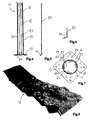
- Figure 1 shows a side view of the lower part of a road pole according to the invention, with an inspection aperture shown without a lid
- Figures 2 and 3 are showing an enlarged part of the road pole of Figure 1 , seen in directions being perpendicular
- Figure 4 shows an axial section of the lower part of the road pole of Figures 1 - 3 .
- Figure 5 shows a side view of a reinforcement band used for the road pole of Figures 1 - 4
- Figure 6 shows an enlarged lower part of the reinforcement band of Figure 5
- Figure 7 shows a plan view from above of a base disc for the road pole of Figures 1 - 4
- Figure 8 shows a collision case, wherein a private car hits a road pole according to the invention
- Figure 9 shows a picture of a part of a road pole according to the invention, which has been hit by a vehicle.
- Figures 1 - 3 show a road pole 11 that is manufactured in the shape of a conical tube 12 with a base flange 13 provided for mounting on a base 14 ( Figure 8 ). Through the base 14, electrical conductors and signal lines can enter the interior of the pole. For connection and maintenance, the road pole has an aperture 15 which can be covered by a lid (not shown).
- FIGs 4 and 7 the arrangement of four reinforcement bands 20, 21, 22, 23, extending from the lower side of the base flange 13, and up to the top of the inspection aperture 15, are shown.
- Figures 5 and 6 show details of a reinforcement band 20, which at the lower end has a downwardly inclined leg 24, which is fastened under the base flange 13 by welding, and which is fastened at its upper end to the interior of the tube 12.
- a reinforcement band is arranged on each side of the aperture 15, and a further two are arranged inside of the aperture, being welded to the wall of the tube 12 through the aperture 15. The reinforcement band will thus, to a substantial degree, be integrated with the tube 12.
- the reinforcement bands 20 - 23 are manufactured of strip steel, with a suitable surface treatment.
- An alternative to strip steel which may be used are materials with corresponding properties e.g. steel rod. It is important to the function, that the reinforcement bands 20 - 23 are integrated into the road pole structure by welding.
- Figure 7 shows the base flange 13 as seen from above, showing the arrangement of the reinforcement bands 20-23.
- the reinforcement bands 20 - 23 will thus inhibit the road pole tearing off during collision, and ensuring a successive flattening over a certain length of the road pole.
- the number of reinforcement bands can differ from the example above.
- the length of the reinforcement bands can be accommodated to the area of use. For road poles for low velocity roads, an extension over a short distance from the base flange may be sufficient.
- the bands can be fastened by welding through holes in the wall of the road pole.
- Figure 8 shows a collision as seen from the side, with a vehicle 25 bending and flattening a road pole 11, according to the invention.
- a flattening zone 26 is created at the front of the vehicle, where the developing zone ascends the road pole 11.
- Figure 9 shows a picture illustrating an example of a deformation developed during a collision with a road pole, according to the invention, with a tube 12.
- the deformation is a flattening which absorbs kinetic energy, and decelerates the vehicle gently to avoid injury to persons. Due to the reinforcement bands 20-23, this can occur without risking the road pole tearing off, and the continued movement of the vehicle with high velocity.
- the inventions provide a favourable combination of static strength which makes the road pole resistant to wind load and other non-traffic related loads. Simultaneously it provides the ability to yield without causing injury to persons, and also decelerates a colliding vehicle gently, to reduce the damage during collision with obstacles in the continued path of the vehicle.
- the road pole of the invention will thus take on the character of a shock absorber instead of being a damaging object. This will apply both to light and heavy private cars.
- the base flange 13 is mounted slightly below ground level, so that a vehicle will always knock the road pole over.
- the road pole is pressed to flatten the tubular structure.
- the upper parts of the road pole will simultaneously be bent in a U-shape around the front of the vehicle, where the flattening zone 26 is created at the transition between the flattened part, and the succeeding upper part of the road pole, which still has its full section.
- the flattening zone a decelerating energy absorption will occur on the forward movement of the vehicle 11.
- This energy absorption is a crucial part of the function of the road pole, according to the invention.
- the proposed slot design has proved to provide favourable energy absorption, combined with low cost and favourable static properties.
- the slots can have a length of 250 - 350 mm, with 300 mm as an assumed optimal length.
- the width of the slots can be from 2 mm down to zero, with 1,5 mm as a value suitable for use, and for manufacturing with a plasma cutter.
- the distance between adjacent slots 16 - 19 can be 20 - 70 mm, e.g. 30 mm in the lower part, with an increasing distance ascending the road pole.
- a 12 meter long road pole was provided with 300 mm long slots up to a level of 8 meters. Under the aperture 15 on a level of 0,8 meter, the distance was 30 mm, wherefrom to a level of 4 -5 meters, the distance was 40 mm, with a distance of 50 mm at the remainin row of slots.
Landscapes
- Engineering & Computer Science (AREA)
- Architecture (AREA)
- Civil Engineering (AREA)
- Structural Engineering (AREA)
- Optical Communication System (AREA)
- Road Signs Or Road Markings (AREA)
- Bipolar Transistors (AREA)
- Semiconductor Lasers (AREA)
- Refuge Islands, Traffic Blockers, Or Guard Fence (AREA)
- Element Separation (AREA)
- Valve Device For Special Equipments (AREA)
- Mechanical Treatment Of Semiconductor (AREA)
- Devices Affording Protection Of Roads Or Walls For Sound Insulation (AREA)
Abstract
Description
- The invention relates to a road pole as stated in the introductory part of claim 1, particularly to be used as a light pole on roads and similar traffic routes, implying a risk of collision with cars and similar vehicles.
- There is a need for designing road poles, particularly light poles and similar poles for traffic routes, to provide retardation of the vehicle during a collision, with as little vehicle body damage and injury to persons as possible. This has resulted in the development of "collision-friendly" road poles with particular deformation zones, which will decelerate the colliding vehicle most gently.
- Known are steel plate road poles, which are folded into an octagonal conical tube, with iron rods welded along the interior of the fold lines. The manufacture of such road poles are time consuming and costly. The current cushioning requirements have not been satisfied either.
- Truss beam poles, designed and dimensioned for providing cushioning during collision are also known. But such poles have been costly. Additionally, they have esthetic drawbacks.
- From German Patent Publication
1 811 147 (Saalmann 1968 ) it is known to weaken the foot of a road pole with a series of slots distributed circumferentially at ground level. This will solve the problem of stiff poles causing damage, but it will be sheared off at the foot, and the vehicle will continue with almost unreduced velocity, due to the low energy absorption. - From
UK-patent specification 2.268.744 (Dowling 1993 - This way of designing road poles has a number of disadvantages. The punching of a multitude of slots requires an expensive tool, and is time consuming. Such road poles will therefore be expensive, and have not been used to any extent.
- From
EP patent application 1 964 (Svensson 1979 - Thus, slots have long been used as a tool in the manufacture of poles for traffic routes. But no solution with optimal strength and providing a decelerating effect on the vehicle, over a sufficient length of pole, to reduce the risk of injury to persons in a secondary collision, has emerged. Also, it has not been possible, with the prior art manufacturing methods, to manufacture a tube with slots with sufficient strength at acceptable cost. This pole design has thus not gained acceptance.
- The main object of the invention is thus to provide a design, and a method of production, for road poles with beneficial properties, regarding carrying capacity and buckling properties, and which decelerates the vehicle over a sufficient distance to manage the requirements for retardation and energy absorption.
- It is a particular object to provide a road pole which can absorb most of the kinetic energy of a vehicle hitting the road pole with a high velocity, to make the road pole safer to traffic. The costs should be kept low to make the novel technology exploitable.
- The invention is stated in claim 1. This design provides a favourable balance between the bending strength and static strength properties on one side, and the dynamic properties during a collision on the other. The proposed structure of the road pole will withstand wind load, while the energy needed for flattening the tubular design during at a collision by a vehicle is approzimate to the kinetic energy of a common private car. Then optimal occurrence is present when the road pole is dimensioned to be completely deformed, i.e. flattened, by a private car hitting it at a high velocity, and thus decelerating the vehicle as much as possible. Road poles according to the invention have been approved at a test carried out according to EU-norms.
- It is known to provide an interior wire to inhibit the road pole tearing away from the base, but this is unsuitable in manufacturing, and expensive. Claims 2 - 10 state particular advantageous embodiments.
- The drawing shows an embodiment, wherein
Figure 1 shows a side view of the lower part of a road pole according to the invention, with an inspection aperture shown without a lid,
Figures 2 and 3 are showing an enlarged part of the road pole ofFigure 1 , seen in directions being perpendicular,
Figure 4 shows an axial section of the lower part of the road pole ofFigures 1 - 3 .
Figure 5 shows a side view of a reinforcement band used for the road pole ofFigures 1 - 4 ,
Figure 6 shows an enlarged lower part of the reinforcement band ofFigure 5 ,
Figure 7 shows a plan view from above of a base disc for the road pole ofFigures 1 - 4 ,
Figure 8 shows a collision case, wherein a private car hits a road pole according to the invention, while
Figure 9 shows a picture of a part of a road pole according to the invention, which has been hit by a vehicle. -
Figures 1 - 3 show a road pole 11 that is manufactured in the shape of aconical tube 12 with abase flange 13 provided for mounting on a base 14 (Figure 8 ). Through thebase 14, electrical conductors and signal lines can enter the interior of the pole. For connection and maintenance, the road pole has anaperture 15 which can be covered by a lid (not shown). - Four axial rows of slots 16 -19 are arranged circumferentially, 90° apart (
Figure 7 ). This selection of slots has proven to provide a favourable balance between the number of slots and the material of the wall, which provides particularly favourable dampening during collision, while the pole has high strength in its initial, static condition, partly due to the reinforcement band or bands. The number of rows of slots can be reduced to three or increased to six, but then less favourable ranges are approached. - It is known to provide slots in road poles by punching plates, which are then folded or pressed into tubular form, however, but this method is time consuming and thus expensive. It has proved advantageous to cut the slots with a plasma cutter. The current economic restriction of using a plasma cutter is connected to the wear at the start of each cut. The design of the slots, having a relatively low number of long slots 16 - 19, will reduce the nozzle costs to an acceptable level. Laser cutting may also be used.
- In
Figures 4 and 7 , the arrangement of fourreinforcement bands base flange 13, and up to the top of theinspection aperture 15, are shown.Figures 5 and 6 show details of areinforcement band 20, which at the lower end has a downwardlyinclined leg 24, which is fastened under thebase flange 13 by welding, and which is fastened at its upper end to the interior of thetube 12. A reinforcement band is arranged on each side of theaperture 15, and a further two are arranged inside of the aperture, being welded to the wall of thetube 12 through theaperture 15. The reinforcement band will thus, to a substantial degree, be integrated with thetube 12. - The reinforcement bands 20 - 23 are manufactured of strip steel, with a suitable surface treatment. An alternative to strip steel which may be used are materials with corresponding properties e.g. steel rod. It is important to the function, that the reinforcement bands 20 - 23 are integrated into the road pole structure by welding.
-
Figure 7 shows thebase flange 13 as seen from above, showing the arrangement of the reinforcement bands 20-23. - The reinforcement bands 20 - 23 will thus inhibit the road pole tearing off during collision, and ensuring a successive flattening over a certain length of the road pole.
- The number of reinforcement bands can differ from the example above. The length of the reinforcement bands can be accommodated to the area of use. For road poles for low velocity roads, an extension over a short distance from the base flange may be sufficient. The bands can be fastened by welding through holes in the wall of the road pole.
-
Figure 8 shows a collision as seen from the side, with avehicle 25 bending and flattening a road pole 11, according to the invention. A flatteningzone 26 is created at the front of the vehicle, where the developing zone ascends the road pole 11. -
Figure 9 shows a picture illustrating an example of a deformation developed during a collision with a road pole, according to the invention, with atube 12. The deformation is a flattening which absorbs kinetic energy, and decelerates the vehicle gently to avoid injury to persons. Due to the reinforcement bands 20-23, this can occur without risking the road pole tearing off, and the continued movement of the vehicle with high velocity. - The inventions provide a favourable combination of static strength which makes the road pole resistant to wind load and other non-traffic related loads. Simultaneously it provides the ability to yield without causing injury to persons, and also decelerates a colliding vehicle gently, to reduce the damage during collision with obstacles in the continued path of the vehicle. The road pole of the invention will thus take on the character of a shock absorber instead of being a damaging object. This will apply both to light and heavy private cars.
- The
base flange 13 is mounted slightly below ground level, so that a vehicle will always knock the road pole over. At the front end of the vehicle, the road pole is pressed to flatten the tubular structure. The upper parts of the road pole will simultaneously be bent in a U-shape around the front of the vehicle, where the flatteningzone 26 is created at the transition between the flattened part, and the succeeding upper part of the road pole, which still has its full section. In the flattening zone, a decelerating energy absorption will occur on the forward movement of the vehicle 11. This energy absorption is a crucial part of the function of the road pole, according to the invention. The proposed slot design has proved to provide favourable energy absorption, combined with low cost and favourable static properties. - The slots can have a length of 250 - 350 mm, with 300 mm as an assumed optimal length. The width of the slots can be from 2 mm down to zero, with 1,5 mm as a value suitable for use, and for manufacturing with a plasma cutter. The distance between adjacent slots 16 - 19 can be 20 - 70 mm, e.g. 30 mm in the lower part, with an increasing distance ascending the road pole.
- In one example, a 12 meter long road pole was provided with 300 mm long slots up to a level of 8 meters. Under the
aperture 15 on a level of 0,8 meter, the distance was 30 mm, wherefrom to a level of 4 -5 meters, the distance was 40 mm, with a distance of 50 mm at the remainin row of slots.
Claims (10)
- Road pole (11), particularly for use as a light pole on roads and similar traffic routes, with a conical tube (12) which is narrowing continuously or stepwise, ascending from a base (14), particularly with a polygonal or circular cross section, wherein the wall of the tube has circumferential distributed rows of axial slots (16-19) and which at the lower end has an integrated base flange (13) for fastening to the base (14), characterized in- that at least the lower part of the road pole has 3 to 6 rows of circumferentially distributed slots (16 - 19), and- that at least one axial reinforcement band (20 - 23) being integrated on the inside of the road pole (11) in its lower part, said element is fastened at least at its lower end to the base flange (13) of the road pole, and at its upper end to the pole wall.
- Road pole according to claim 1, characterized in that four steel reinforcements bands (20 - 23) are distributed circumferentially, extending along the walls of the conical tube (12).
- Road pole according to claim 1 or 2, characterized in that four rows of slots (16-19) are arranged circumferentially.
- Road pole according to anyone of claims 1-3, characterized in that the axial distance between adjoining slots is approzimately 1/5 - approximately 1/15 of the length of the slots.
- Road pole according to claim 4, characterized in that the distance between the slots (16 -19) axially is increasing continuously or stepwise from the base end.
- Road pole according to anyone of the claims 1-5, characterized in that the slots have a length of 250 - 400 mm and a mutual distance of 25 - 70 mm, at a wall, thickness of approximately 3 mm.
- Road pole according to claim 6, characterized in that the slots in the lower part have a length of approximately 300 mm and a mutual distance of approximately 30 mm.
- Road pole according to anyone of the claims 1 -7, characterized in that the reinforcement band or bands (20 - 23) is/are fastened to the base flange (13) of the tube (12) at its/their lower end (24) and at its/their upper end at the level of an inspection aperture (15).
- Road pole according to claim 8, characterized in that the reinforcement band or bands (20 - 23) is/are fastened to the base flange (13) by welding.
- Road pole according to claim 9, characterized in that the reinforcement band or bands is/are at a strip steel with a J-shaped lower end (24).
Priority Applications (1)
| Application Number | Priority Date | Filing Date | Title |
|---|---|---|---|
| PL04808850T PL1709250T3 (en) | 2003-12-29 | 2004-11-19 | Road pole |
Applications Claiming Priority (3)
| Application Number | Priority Date | Filing Date | Title |
|---|---|---|---|
| NO20035826 | 2003-12-29 | ||
| NO20044680A NO322873B1 (en) | 2003-12-29 | 2004-10-29 | Road pole |
| PCT/NO2004/000356 WO2005064084A1 (en) | 2003-12-29 | 2004-11-19 | Road pole |
Publications (2)
| Publication Number | Publication Date |
|---|---|
| EP1709250A1 EP1709250A1 (en) | 2006-10-11 |
| EP1709250B1 true EP1709250B1 (en) | 2010-06-02 |
Family
ID=34742246
Family Applications (1)
| Application Number | Title | Priority Date | Filing Date |
|---|---|---|---|
| EP04808850A Expired - Lifetime EP1709250B1 (en) | 2003-12-29 | 2004-11-19 | Road pole |
Country Status (7)
| Country | Link |
|---|---|
| EP (1) | EP1709250B1 (en) |
| AT (1) | ATE470018T1 (en) |
| DE (1) | DE602004027546D1 (en) |
| DK (1) | DK1709250T3 (en) |
| NO (1) | NO322873B1 (en) |
| PL (1) | PL1709250T3 (en) |
| WO (1) | WO2005064084A1 (en) |
Families Citing this family (6)
| Publication number | Priority date | Publication date | Assignee | Title |
|---|---|---|---|---|
| AU2008229948B2 (en) * | 2008-10-15 | 2016-08-11 | Plasgain Pty Ltd | An Impact Absorbing Pole |
| US20130008096A1 (en) * | 2010-04-01 | 2013-01-10 | Michael Griffiths | Utility pole |
| CN106232902A (en) * | 2014-03-14 | 2016-12-14 | 安全产品公司 | street column |
| SE538222C2 (en) * | 2014-06-12 | 2016-04-05 | Northcone Ab | Pole arrangements |
| NZ742498A (en) * | 2015-12-18 | 2023-05-26 | Ind Galvanizers Corp Pty Ltd | A support |
| CN113073894A (en) * | 2021-04-09 | 2021-07-06 | 广东欣粤电力器材有限公司 | Anti-collision composite material electric pole |
Family Cites Families (5)
| Publication number | Priority date | Publication date | Assignee | Title |
|---|---|---|---|---|
| DE1811147A1 (en) * | 1968-11-27 | 1970-06-18 | Wilhelm Saalmann | Safety marker post |
| SE354497B (en) * | 1972-05-09 | 1973-03-12 | Wikstrand & Berg Wibe Ab | |
| US4196550A (en) * | 1977-11-09 | 1980-04-08 | Lars Svensson | Post |
| SE445656B (en) * | 1983-12-13 | 1986-07-07 | Sven Runo Vilhelm Gebelius | DEVICE FOR A TARGET ELEMENT THERE IS A FLEXIBLE TAPE, THE LENGTH OF WHICH SUBSTANTLY EXCEEDS THE LENGTH BETWEEN ITS POINTS IN THE TARGET ELEMENT AND FOUNDATION |
| AU631104B3 (en) * | 1992-07-17 | 1992-11-12 | Lysaght (Malaysia) SDN. BHD. | Energy absorbing pole |
-
2004
- 2004-10-29 NO NO20044680A patent/NO322873B1/en unknown
- 2004-11-19 DK DK04808850.4T patent/DK1709250T3/en active
- 2004-11-19 DE DE602004027546T patent/DE602004027546D1/en not_active Expired - Lifetime
- 2004-11-19 EP EP04808850A patent/EP1709250B1/en not_active Expired - Lifetime
- 2004-11-19 WO PCT/NO2004/000356 patent/WO2005064084A1/en not_active Ceased
- 2004-11-19 PL PL04808850T patent/PL1709250T3/en unknown
- 2004-11-19 AT AT04808850T patent/ATE470018T1/en not_active IP Right Cessation
Also Published As
| Publication number | Publication date |
|---|---|
| ATE470018T1 (en) | 2010-06-15 |
| NO322873B1 (en) | 2006-12-18 |
| EP1709250A1 (en) | 2006-10-11 |
| DK1709250T3 (en) | 2010-09-27 |
| NO20044680D0 (en) | 2004-10-29 |
| PL1709250T3 (en) | 2010-12-31 |
| DE602004027546D1 (en) | 2010-07-15 |
| NO20044680L (en) | 2005-06-30 |
| WO2005064084A1 (en) | 2005-07-14 |
Similar Documents
| Publication | Publication Date | Title |
|---|---|---|
| US6558067B2 (en) | Guardrail beam with enhanced stability | |
| AU2002365808B2 (en) | Steel yielding guardrail support post | |
| KR20070005644A (en) | Bumper Beam for Vehicle | |
| AU9711498A (en) | Highway barrier and guardrail | |
| SE509041C2 (en) | Vehicle impact protection beam | |
| US20060099030A1 (en) | Vehicle impact attenuator | |
| EP1709250A1 (en) | Road pole | |
| EP1728924B1 (en) | Device for holding sliding masses or bodies | |
| EP0575705B1 (en) | Metallic safety barrier | |
| WO1979000391A1 (en) | Post mounting | |
| EP2735652B1 (en) | A traffic-safe and collision energy absorbing pole | |
| KR20120001028U (en) | Shock absorbing reinforced Guard rail | |
| JP3700521B2 (en) | Road guard fence post | |
| US20070063179A1 (en) | A weakened guardrail mounting connection | |
| KR102077319B1 (en) | A cushioning reinforcement for a holding post, the holding post having the same, and a guard rail comprising the holding post | |
| CN218990015U (en) | Novel road guardrail | |
| EP1382748B1 (en) | Guardrail terminal | |
| EP4148184B1 (en) | Foundation for supporting a post and arrangement for improved safety in connection to support structures for road equipment | |
| NZ247817A (en) | Impact absorbing tubular pole: wall with alternating first and second pairs of staggered slits | |
| CN211285426U (en) | Urban road guardrail | |
| US20070063178A1 (en) | Guardrail flange protector | |
| US20040114996A1 (en) | Front impact damper | |
| US20140043836A1 (en) | Yieldable lighting column | |
| US20070063177A1 (en) | Yielding post guardrail safety system | |
| KR101585734B1 (en) | Guard Rail Post And Guard Fence Having the Same |
Legal Events
| Date | Code | Title | Description |
|---|---|---|---|
| PUAI | Public reference made under article 153(3) epc to a published international application that has entered the european phase |
Free format text: ORIGINAL CODE: 0009012 |
|
| 17P | Request for examination filed |
Effective date: 20060728 |
|
| AK | Designated contracting states |
Kind code of ref document: A1 Designated state(s): AT BE BG CH CY CZ DE DK EE ES FI FR GB GR HU IE IS IT LI LU MC NL PL PT RO SE SI SK TR |
|
| DAX | Request for extension of the european patent (deleted) | ||
| GRAP | Despatch of communication of intention to grant a patent |
Free format text: ORIGINAL CODE: EPIDOSNIGR1 |
|
| GRAS | Grant fee paid |
Free format text: ORIGINAL CODE: EPIDOSNIGR3 |
|
| GRAA | (expected) grant |
Free format text: ORIGINAL CODE: 0009210 |
|
| AK | Designated contracting states |
Kind code of ref document: B1 Designated state(s): AT BE BG CH CY CZ DE DK EE ES FI FR GB GR HU IE IS IT LI LU MC NL PL PT RO SE SI SK TR |
|
| REG | Reference to a national code |
Ref country code: GB Ref legal event code: FG4D |
|
| REG | Reference to a national code |
Ref country code: CH Ref legal event code: EP |
|
| REG | Reference to a national code |
Ref country code: IE Ref legal event code: FG4D |
|
| REF | Corresponds to: |
Ref document number: 602004027546 Country of ref document: DE Date of ref document: 20100715 Kind code of ref document: P |
|
| REG | Reference to a national code |
Ref country code: NL Ref legal event code: T3 |
|
| REG | Reference to a national code |
Ref country code: SE Ref legal event code: TRGR |
|
| REG | Reference to a national code |
Ref country code: DK Ref legal event code: T3 |
|
| PG25 | Lapsed in a contracting state [announced via postgrant information from national office to epo] |
Ref country code: SI Free format text: LAPSE BECAUSE OF FAILURE TO SUBMIT A TRANSLATION OF THE DESCRIPTION OR TO PAY THE FEE WITHIN THE PRESCRIBED TIME-LIMIT Effective date: 20100602 Ref country code: AT Free format text: LAPSE BECAUSE OF FAILURE TO SUBMIT A TRANSLATION OF THE DESCRIPTION OR TO PAY THE FEE WITHIN THE PRESCRIBED TIME-LIMIT Effective date: 20100602 |
|
| PG25 | Lapsed in a contracting state [announced via postgrant information from national office to epo] |
Ref country code: GR Free format text: LAPSE BECAUSE OF FAILURE TO SUBMIT A TRANSLATION OF THE DESCRIPTION OR TO PAY THE FEE WITHIN THE PRESCRIBED TIME-LIMIT Effective date: 20100903 Ref country code: CY Free format text: LAPSE BECAUSE OF FAILURE TO SUBMIT A TRANSLATION OF THE DESCRIPTION OR TO PAY THE FEE WITHIN THE PRESCRIBED TIME-LIMIT Effective date: 20100602 |
|
| REG | Reference to a national code |
Ref country code: PL Ref legal event code: T3 |
|
| PG25 | Lapsed in a contracting state [announced via postgrant information from national office to epo] |
Ref country code: EE Free format text: LAPSE BECAUSE OF FAILURE TO SUBMIT A TRANSLATION OF THE DESCRIPTION OR TO PAY THE FEE WITHIN THE PRESCRIBED TIME-LIMIT Effective date: 20100602 |
|
| PG25 | Lapsed in a contracting state [announced via postgrant information from national office to epo] |
Ref country code: CZ Free format text: LAPSE BECAUSE OF FAILURE TO SUBMIT A TRANSLATION OF THE DESCRIPTION OR TO PAY THE FEE WITHIN THE PRESCRIBED TIME-LIMIT Effective date: 20100602 Ref country code: SK Free format text: LAPSE BECAUSE OF FAILURE TO SUBMIT A TRANSLATION OF THE DESCRIPTION OR TO PAY THE FEE WITHIN THE PRESCRIBED TIME-LIMIT Effective date: 20100602 Ref country code: RO Free format text: LAPSE BECAUSE OF FAILURE TO SUBMIT A TRANSLATION OF THE DESCRIPTION OR TO PAY THE FEE WITHIN THE PRESCRIBED TIME-LIMIT Effective date: 20100602 Ref country code: IS Free format text: LAPSE BECAUSE OF FAILURE TO SUBMIT A TRANSLATION OF THE DESCRIPTION OR TO PAY THE FEE WITHIN THE PRESCRIBED TIME-LIMIT Effective date: 20101002 Ref country code: PT Free format text: LAPSE BECAUSE OF FAILURE TO SUBMIT A TRANSLATION OF THE DESCRIPTION OR TO PAY THE FEE WITHIN THE PRESCRIBED TIME-LIMIT Effective date: 20101004 |
|
| PG25 | Lapsed in a contracting state [announced via postgrant information from national office to epo] |
Ref country code: IT Free format text: LAPSE BECAUSE OF FAILURE TO SUBMIT A TRANSLATION OF THE DESCRIPTION OR TO PAY THE FEE WITHIN THE PRESCRIBED TIME-LIMIT Effective date: 20100602 |
|
| PLBE | No opposition filed within time limit |
Free format text: ORIGINAL CODE: 0009261 |
|
| STAA | Information on the status of an ep patent application or granted ep patent |
Free format text: STATUS: NO OPPOSITION FILED WITHIN TIME LIMIT |
|
| 26N | No opposition filed |
Effective date: 20110303 |
|
| REG | Reference to a national code |
Ref country code: DE Ref legal event code: R097 Ref document number: 602004027546 Country of ref document: DE Effective date: 20110302 |
|
| PG25 | Lapsed in a contracting state [announced via postgrant information from national office to epo] |
Ref country code: MC Free format text: LAPSE BECAUSE OF NON-PAYMENT OF DUE FEES Effective date: 20101130 |
|
| REG | Reference to a national code |
Ref country code: CH Ref legal event code: PL |
|
| PG25 | Lapsed in a contracting state [announced via postgrant information from national office to epo] |
Ref country code: LI Free format text: LAPSE BECAUSE OF NON-PAYMENT OF DUE FEES Effective date: 20101130 Ref country code: CH Free format text: LAPSE BECAUSE OF NON-PAYMENT OF DUE FEES Effective date: 20101130 |
|
| PG25 | Lapsed in a contracting state [announced via postgrant information from national office to epo] |
Ref country code: IE Free format text: LAPSE BECAUSE OF NON-PAYMENT OF DUE FEES Effective date: 20101119 |
|
| PG25 | Lapsed in a contracting state [announced via postgrant information from national office to epo] |
Ref country code: BG Free format text: LAPSE BECAUSE OF FAILURE TO SUBMIT A TRANSLATION OF THE DESCRIPTION OR TO PAY THE FEE WITHIN THE PRESCRIBED TIME-LIMIT Effective date: 20100602 Ref country code: HU Free format text: LAPSE BECAUSE OF FAILURE TO SUBMIT A TRANSLATION OF THE DESCRIPTION OR TO PAY THE FEE WITHIN THE PRESCRIBED TIME-LIMIT Effective date: 20101203 Ref country code: LU Free format text: LAPSE BECAUSE OF NON-PAYMENT OF DUE FEES Effective date: 20101119 |
|
| PG25 | Lapsed in a contracting state [announced via postgrant information from national office to epo] |
Ref country code: TR Free format text: LAPSE BECAUSE OF FAILURE TO SUBMIT A TRANSLATION OF THE DESCRIPTION OR TO PAY THE FEE WITHIN THE PRESCRIBED TIME-LIMIT Effective date: 20100602 |
|
| PG25 | Lapsed in a contracting state [announced via postgrant information from national office to epo] |
Ref country code: BG Free format text: LAPSE BECAUSE OF FAILURE TO SUBMIT A TRANSLATION OF THE DESCRIPTION OR TO PAY THE FEE WITHIN THE PRESCRIBED TIME-LIMIT Effective date: 20100902 |
|
| PG25 | Lapsed in a contracting state [announced via postgrant information from national office to epo] |
Ref country code: ES Free format text: LAPSE BECAUSE OF FAILURE TO SUBMIT A TRANSLATION OF THE DESCRIPTION OR TO PAY THE FEE WITHIN THE PRESCRIBED TIME-LIMIT Effective date: 20100913 |
|
| REG | Reference to a national code |
Ref country code: FR Ref legal event code: PLFP Year of fee payment: 12 |
|
| REG | Reference to a national code |
Ref country code: FR Ref legal event code: PLFP Year of fee payment: 13 |
|
| REG | Reference to a national code |
Ref country code: FR Ref legal event code: PLFP Year of fee payment: 14 |
|
| P01 | Opt-out of the competence of the unified patent court (upc) registered |
Effective date: 20230526 |
|
| PGFP | Annual fee paid to national office [announced via postgrant information from national office to epo] |
Ref country code: NL Payment date: 20231120 Year of fee payment: 20 |
|
| PGFP | Annual fee paid to national office [announced via postgrant information from national office to epo] |
Ref country code: GB Payment date: 20231123 Year of fee payment: 20 |
|
| PGFP | Annual fee paid to national office [announced via postgrant information from national office to epo] |
Ref country code: SE Payment date: 20231120 Year of fee payment: 20 Ref country code: FR Payment date: 20231120 Year of fee payment: 20 Ref country code: FI Payment date: 20231121 Year of fee payment: 20 Ref country code: DK Payment date: 20231124 Year of fee payment: 20 Ref country code: DE Payment date: 20231121 Year of fee payment: 20 |
|
| PGFP | Annual fee paid to national office [announced via postgrant information from national office to epo] |
Ref country code: PL Payment date: 20231109 Year of fee payment: 20 Ref country code: BE Payment date: 20231120 Year of fee payment: 20 |
|
| REG | Reference to a national code |
Ref country code: DE Ref legal event code: R071 Ref document number: 602004027546 Country of ref document: DE |
|
| REG | Reference to a national code |
Ref country code: NL Ref legal event code: MK Effective date: 20241118 |
|
| REG | Reference to a national code |
Ref country code: DK Ref legal event code: EUP Expiry date: 20241119 |
|
| REG | Reference to a national code |
Ref country code: GB Ref legal event code: PE20 Expiry date: 20241118 |
|
| REG | Reference to a national code |
Ref country code: BE Ref legal event code: MK Effective date: 20241119 |
|
| REG | Reference to a national code |
Ref country code: SE Ref legal event code: EUG |
|
| PG25 | Lapsed in a contracting state [announced via postgrant information from national office to epo] |
Ref country code: GB Free format text: LAPSE BECAUSE OF EXPIRATION OF PROTECTION Effective date: 20241118 |
|
| PG25 | Lapsed in a contracting state [announced via postgrant information from national office to epo] |
Ref country code: GB Free format text: LAPSE BECAUSE OF EXPIRATION OF PROTECTION Effective date: 20241118 |