EP1708855B1 - Bidirectional shaving implement - Google Patents
Bidirectional shaving implement Download PDFInfo
- Publication number
- EP1708855B1 EP1708855B1 EP05712764A EP05712764A EP1708855B1 EP 1708855 B1 EP1708855 B1 EP 1708855B1 EP 05712764 A EP05712764 A EP 05712764A EP 05712764 A EP05712764 A EP 05712764A EP 1708855 B1 EP1708855 B1 EP 1708855B1
- Authority
- EP
- European Patent Office
- Prior art keywords
- cartridge
- razor
- razor cartridge
- platform portion
- pair
- Prior art date
- Legal status (The legal status is an assumption and is not a legal conclusion. Google has not performed a legal analysis and makes no representation as to the accuracy of the status listed.)
- Not-in-force
Links
Images

Classifications
-
- B—PERFORMING OPERATIONS; TRANSPORTING
- B26—HAND CUTTING TOOLS; CUTTING; SEVERING
- B26B—HAND-HELD CUTTING TOOLS NOT OTHERWISE PROVIDED FOR
- B26B21/00—Razors of the open or knife type; Safety razors or other shaving implements of the planing type; Hair-trimming devices involving a razor-blade; Equipment therefor
- B26B21/40—Details or accessories
- B26B21/52—Handles, e.g. tiltable, flexible
- B26B21/521—Connection details, e.g. connection to razor heads
-
- B—PERFORMING OPERATIONS; TRANSPORTING
- B26—HAND CUTTING TOOLS; CUTTING; SEVERING
- B26B—HAND-HELD CUTTING TOOLS NOT OTHERWISE PROVIDED FOR
- B26B21/00—Razors of the open or knife type; Safety razors or other shaving implements of the planing type; Hair-trimming devices involving a razor-blade; Equipment therefor
- B26B21/08—Razors of the open or knife type; Safety razors or other shaving implements of the planing type; Hair-trimming devices involving a razor-blade; Equipment therefor involving changeable blades
- B26B21/14—Safety razors with one or more blades arranged transversely to the handle
- B26B21/22—Safety razors with one or more blades arranged transversely to the handle involving several blades to be used simultaneously
- B26B21/222—Safety razors with one or more blades arranged transversely to the handle involving several blades to be used simultaneously with the blades moulded into, or attached to, a changeable unit
- B26B21/225—Safety razors with one or more blades arranged transversely to the handle involving several blades to be used simultaneously with the blades moulded into, or attached to, a changeable unit the changeable unit being resiliently mounted on the handle
-
- B—PERFORMING OPERATIONS; TRANSPORTING
- B26—HAND CUTTING TOOLS; CUTTING; SEVERING
- B26B—HAND-HELD CUTTING TOOLS NOT OTHERWISE PROVIDED FOR
- B26B21/00—Razors of the open or knife type; Safety razors or other shaving implements of the planing type; Hair-trimming devices involving a razor-blade; Equipment therefor
- B26B21/08—Razors of the open or knife type; Safety razors or other shaving implements of the planing type; Hair-trimming devices involving a razor-blade; Equipment therefor involving changeable blades
- B26B21/14—Safety razors with one or more blades arranged transversely to the handle
- B26B21/22—Safety razors with one or more blades arranged transversely to the handle involving several blades to be used simultaneously
- B26B21/222—Safety razors with one or more blades arranged transversely to the handle involving several blades to be used simultaneously with the blades moulded into, or attached to, a changeable unit
- B26B21/227—Safety razors with one or more blades arranged transversely to the handle involving several blades to be used simultaneously with the blades moulded into, or attached to, a changeable unit with blades being resiliently mounted in the changeable unit
-
- B—PERFORMING OPERATIONS; TRANSPORTING
- B26—HAND CUTTING TOOLS; CUTTING; SEVERING
- B26B—HAND-HELD CUTTING TOOLS NOT OTHERWISE PROVIDED FOR
- B26B21/00—Razors of the open or knife type; Safety razors or other shaving implements of the planing type; Hair-trimming devices involving a razor-blade; Equipment therefor
- B26B21/40—Details or accessories
- B26B21/4006—Blades or blade units with discontinuous cutting edges, e.g. wire-wrapped, notches
-
- B—PERFORMING OPERATIONS; TRANSPORTING
- B26—HAND CUTTING TOOLS; CUTTING; SEVERING
- B26B—HAND-HELD CUTTING TOOLS NOT OTHERWISE PROVIDED FOR
- B26B21/00—Razors of the open or knife type; Safety razors or other shaving implements of the planing type; Hair-trimming devices involving a razor-blade; Equipment therefor
- B26B21/40—Details or accessories
- B26B21/52—Handles, e.g. tiltable, flexible
- B26B21/522—Ergonomic details, e.g. shape, ribs or rubber parts
Abstract
Description
- The present invention generally relates to wet shaving implements and is more particularly directed to a shaving implement able to cut hair when drawn over a user's skin in either of two generally opposite directions.
- Wet shaving razors typically incorporate razor cartridges that have one or more razor blades mounted in a housing with each razor blade having an exposed cutting edge. Generally, the razor can only be drawn in a single direction over a user's skin to cut hair and must be repositioned for each subsequent stroke. When shaving large areas, like the surface of a leg, the need to reposition the shaving implement increases the time required to complete a shaving operation. Another difficulty can occur when shaving hard to reach areas that have complex contours, such as, for example, an armpit. It can become cumbersome to reposition the razor prior to each stroke. Based on at least these difficulties, there is a need for a razor, the use of which does not require that the razor be repositioned prior to each stroke.
- In an effort to address the above-described problems and drawbacks, wet shave razors were developed wherein two or more blades were positioned in a razor cartridge so that the cutting edges of the blades faced away from one another. Shaving implements configured in this fashion were capable of cutting hair when drawn over a user's skin in either of two generally opposite directions. However, due to the blades facing away from each other, and the fact that no friction reducing materials were employed in the razor, significant amounts of drag and thereby discomfort resulted as the razor was drawn across the user's skin.
- Another problem associated with prior art razors configured in the above-described manner was that they either did not pivot at all, or the range of pivotal motion, relative to the handle on which the cartridge was mounted, was insufficient to allow the cutting edges of the razor blades to follow the contours of the user's skin and to allow for an effective reversal of the cutting direction.
- Another drawback associated with the aforementioned prior art, outwardly facing, opposed blade systems, is that during a shaving operation, the line of action of the force that moves the blades in the direction of the cut pushes the blade. This has the potential to cause blade chatter or overturning moments. Either of these occurrences can result in an uncomfortable shaving experience.
- Another difficulty encountered when using the prior art razors sometimes occurred when a user reversed the stroke direction. Often this resulted in a slightly sideways movement of the blades against the user's skin. Because the cutting edges of the blades were generally completely exposed, this motion resulted in nicking or cutting of the skin.
- A razor cartridge as defined in the preamble of claim 1 and for cutting hair by moving the cartridge over a user's skin in either of two generally opposite directions is known from
WO-A-96/32232 - Based on the foregoing, it is the general object of the present invention to provide a wet shave razor that overcomes or improves upon the problems and drawbacks associated with prior art shaving implements.
- The present invention is directed to a razor cartridge as defined in claim 1 and a shaving implement as defined in
claim 20. The dependent claims relate to individual embodiments. - In the preferred embodiment of the present invention, the platform portion and the first and second cartridge sections are integral with one another. However, the present invention is not limited in this regard as the cartridge sections can also be releasably or permanently coupled to the platform portion without departing from the broader aspects of the present invention. First and second limiting surfaces are located on an underside of the platform portion adjacent to one end. Third and fourth limiting surfaces are also positioned on the underside of the platform portion and are located adjacent to an opposing end thereof. The limiting surfaces are configured so as to establish a range of rotational movement of the razor cartridge when rotatably mounted on a razor handle. The limiting surface contact portion of the handle limits cartridge rotation. Preferably, the range of rotational movement is between approximately 0° and 90°. However, the present invention is not limited in this regard as other rotational ranges that are more than, or less than, 90° can be employed.
- Preferably, the platform portion defines a plurality of apertures to allow shaving debris to be washed through and out of the razor cartridge. In addition, the first cartridge section includes a first housing and the second cartridge section includes a second housing. A first blade retainer having the first pair of razor blades coupled thereto is positioned in the first housing for movement between a neutral position and a retracted position in response to forces generated during a shaving operation. Likewise, a second blade retainer having the second pair of razor blades coupled thereto is positioned in the second housing for movement between a neutral position and a retracted position in response to forces generated during the shaving operation. Biasing means are located in each of the first and second housings for normally urging the first and second blade retainers toward the neutral position.
- Preferably, the first and second cartridge sections define a gap therebetween. In an embodiment of the present invention, a first guard element is coupled to the first housing, and a second guard element is coupled to the second housing. In general, during a shaving operation, the guard elements act to stretch the user's skin, thereby providing a surface more conducive to cutting hair. The razor cartridge of the present invention can also include at least one comfort strip. Preferably, two comfort strips would be provided, one coupled to each of the first and the second cartridge sections. In addition, at least one comfort strip can be positioned in the gap between the first and second cartridge sections. However, the present invention is not limited in this regard as any number of comfort or glide strips can be attached to the razor cartridge without departing from the broader aspects of the present invention.
- In another aspect, the present invention resides in a shaving implement incorporating the above-described razor cartridge either permanently or releasably coupled to a handle, In this instance, the razor cartridge preferably has a range of rotation relative to the handle, due to the orientation of the above-described limiting surfaces from a neutral position to approximately 70°. A biasing member projects outwardly from the handle and engages an abutment surface on the platform portion of the razor cartridge to normally urge the razor cartridge toward a neutral position.
-
-
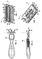
FIG. 1 is a perspective view of a razor cartridge configured in accordance with the present invention. -
FIG. 2 is a cross-sectional side view of the razor cartridge ofFIG. 1 . -
FIG. 3 is a perspective view of the underside of the razor cartridge ofFIG. 1 . -
FIG. 4 is a front view of a a razor handle attachable to the razor cartridge ofFIG. 1 . -
FIG. 5 is a side view of the handle ofFIG. 4 . -
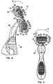
FIG. 6 is a rear view of a shaving implement showing the razor cartridge ofFIG. 1 coupled to the handle ofFIG. 4 . -
FIG. 7 is a cross-sectional side view of the shaving implement ofFIG. 6 . -
FIG. 8 is an enlarged view of a portion, bounded by the circle labeled "A" of the shaving implement ofFIG. 7 . -
FIG. 9 is a front view of the shaving implement ofFIG. 6 . -
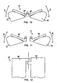
FIG. 10 is a side view of an embodiment of the present invention. -
FIG. 11 is a side view of another embodiment of the present invention. -
FIG. 12 is an enlarged partial view of the razor cartridge ofFIG. 10 . - As shown in
FIGS. 1 -3 , a razor cartridge embodying the present invention and generally designated by thereference number 10 includes aplatform portion 12 having first and second cartridge sections, 14 and 16 respectively, mounted thereon. Thefirst cartridge section 14 includes afirst housing 18, and thesecond cartridge section 16 includes asecond housing 20. Afirst blade retainer 22, best seen inFIG. 2 , is positioned in thefirst housing 18, and asecond blade retainer 24 is positioned in thesecond housing 20. The first and second blade retainers, 22 and 24 respectively, are each movable between a neutral position, where the blade retainers are positioned closest to the leading edges of the first and second blade housings, 18 and 20 respectively, and a retracted position where the blade retainers are located away from the leading edges. A spring (not shown) is positioned in each cartridge section to normally urge the blade retainers toward the neutral position. The first and second cartridge sections, 14 and 16 respectively, have been described as being mounted on theplatform portion 12. The term "mounted" should be broadly construed to mean integral with the platform portion, permanently coupled to it, or releasably coupled to it. - As best shown in
FIG. 2 , a pair ofrazor blades edge 34. Therazor blades razor blades first blade retainer 22 generally face toward the cutting edges of the razor blades mounted in thesecond blade retainer 24. In this manner, therazor cartridge 10 can cut hair by being drawn over a user's skin in either of two generally opposite directions. While eachcartridge section - Referring to
FIG. 1 , the first and second pair ofrazor blades wire 35 that extends over the cutting edges 34 to limit the amount by which a user's skin can extrude between successive razor blades. While wire wrapped razor blades have been shown and described, the present invention is not limited in this regard as other features for inhibiting skin extrusions known to those skilled in the pertinent art to which the present invention pertains, such as, but not limited to protuberances between successive blades, can be substituted. - Referring to
FIGS. 3 and7-9 , theplatform portion 12 includes first and second limiting surfaces generally designated by thereference number 36 located at one end of the platform portion, and third and fourth limiting surfaces generally designed by thereference number 37 located at a generally opposite end of the platform portion. When therazor cartridge 10 is rotatably mounted on ahandle 40, the limitingsurfaces arms 42 that extend from the handle. Preferably, the range of rotation of therazor cartridge 10 is forward and rearward between a neutral position as shown inFIGS. 7-9 and a fully rotated position (not shown) and is between approximately 70° to 90°, as indicated by the arrows labeled "B", inFIG. 8 . However, the present invention is not limited in this regard as the range of motion can be 0° or any other angular amount without departing from the broader aspects of the present invention. In addition to moving in a forward and rearward motion when mounted on a razor handle, the shaving implement may also be configured to allow the razor cartridge to move in a side-to-side rotation as indicated by the arrows labeled "C" inFIG. 9 . Cardanic motion is achieved when the razor cartridge is movable in a forward and rearward direction simultaneously with side-to-side motion. - Referring now to
FIGS. 3 and8 , theplatform portion 12 includes anabutment surface 44, shown in the illustrated embodiment as being circular in cross section; however, the invention is not limited in this regard. When therazor cartridge 10 is mounted, either permanently or releasably to thehandle 40,FIGS. 4 and 5 , a resilient biasingmember 46 projecting outwardly from the handle, engages theabutment surface 44 and normally urges therazor cartridge 10 toward the neutral position. Theplatform portion 12 also includes a plurality ofapertures 48 that aid in allowing shaving debris to be washed through therazor cartridge 10 during a shaving operation. Furthermore, theplatform portion 12 includes a pair ofopposed recesses 50, each adapted to slidably receive anend 52 of mountingarms 42 that form part of thehandle 40. Mountingarms 42 can be movable to allow a disposable razor cartridge to be releasably mounted to thehandle 40, or they can be fixed and the razor cartridge mounted permanently thereon. Whilerecesses 50, and mountingarms 42 have been shown and described, the present invention is not limited in this regard as other means of mounting a razor cartridge to a handle, know to those skilled in the particular art to which the invention pertains, can be substituted. For example, the razor cartridge and handle can be configured to snappingly engage one another, or shell bearings can be employed. - Referring to
FIGS. 1 ,2 and9 , the first and second cartridge sections, 14 and 16 respectively, define agap 56 therebetween. In addition, aguard element 58 is coupled to each of the first and second housings, 14 and 16 respectively, adjacent to the leading edges thereof. During a shaving operation, theguard elements 58 aid in stretching the skin prior to contact with the cutting edges of the razor blades. Comfort strips 59 can also be provided on the first and second housings, 18 and 20 respectively and/or in thegap 56 between the first and second cartridge sections, 14 and 16 respectively. The comfort strips can incorporate a shaving aid thereon such as, but not limited to Polyox®, aloe, vitamins, gels, or oils, or they can incorporate a low friction material to reduce discomfort during a shaving operation. When the comfort strips 59 are formed from low friction material, they are referred to by those skilled in the pertinent art to which the present invention pertains, as "glide strips." Whileguard elements 58 and comfort strips 59 have been shown as being mounted to therazor cartridge 10 in a particular configuration, the present invention is not limited in this regard. Theguard elements 58 and comfort strips 59 can be omitted, interchanged or positioned in any combination on therazor cartridge 10 without departing from the broader aspects of the present invention. - As shown in
FIG. 10 , theplatform portion 12 can include a pair of areas of reducedcross-section 60, one adjacent to each of the first and second cartridge sections, 14 and 16 respectively. The areas of reducedcross section 60 allow theplatform portion 12 to flex so that the first and second cartridge sections, 14 and 16 respectively, can move, as indicated by the arrows labeled "A", during a shaving operation to more closely follow the contours of a user's skin. - Referring to
FIGS. 11 and 12 , theplatform portion 12 is formed from first and second platform halves, 62 and 64 respectively, hingedly coupled to one another. Eachplatform half - While preferred embodiments have been shown and described, various modifications and substitutions may be made without departing from the scope of the invention. Accordingly, it is to be understood that the present invention has been described by way of example, and not by limitation.
Claims (25)
- A razor cartridge (10) comprising:- a platform portion (12) having a first cartridge section (14) including at least one first pair of razor blades (30) positioned therein, each of said first pair of razor blades (30) having an at least partially exposed cutting edge (34), and a separate second cartridge section (16) coupled to said platform portion (12), said second cartridge section (16) including at least one second pair of razor blades (32) positioned therein, each of said second pair of razor blades (32) having an at least partially exposed cutting edge (34), and- mounting means for coupling said platform portion (12) to a handle (40);- wherein said cutting edges (34) of said first pair of razor blades (30) are positioned opposite and facing toward said cutting edges (34) of said second pair of razor blades (32) so that during a shaving operation, the razor cartridge (10) can cut hair when drawn over a user's skin in either of two generally opposite directions,
characterized in that- said first cartridge section (14) includes a first housing (18) coupled to said platform portion (12), said first pair of razor blades (30) being positioned in said first housing (18), and- said second cartridge section (16) includes a separate second housing (20) coupled to said platform portion (12), said second pair of razor blades (32) being positioned in said second housing (20). - A razor cartridge (10) as defined by claim 1, wherein said platform portion (12) and said first cartridge section (14) and said second cartridge section (16) are integral with one another.
- A razor cartridge (10) as defined by claim 1 or 2, wherein said platform portion (12) is rotatably mountable to said handle (40) and defines first and second limiting surfaces (36) positioned on an underside thereof adjacent to a first end of said platform portion (12), and third and forth limiting surfaces (37) positioned on said underside of said platform portion (12) adjacent to a second opposing end of said platform portion (12), said limiting surfaces (36,37) being configured relative to one another to establish a range of rotational movement of said razor cartridge (10) relative to said handle (40) when said razor cartridge (10) is rotatably mounted thereon.
- A razor cartridge (10) as defined by claim 3, wherein said range of rotational movement is between 0° to approximately 90° or is approximately 70° or approximately 45° or approximately 90°.
- A razor cartridge (10) as defined by any one of claims 1 to 4, wherein said platform portion (12) defines a plurality of apertures (48) extending there through to allow shaving debris to be washed from said razor cartridge (10).
- A razor cartridge (10) as defined by any one of claims 1 to 5, wherein- a first blade retainer (22) having said first pair of razor blades (30) coupled thereto is positioned in said first housing (18) for movement between a neutral position and a retracted position;- a second blade retainer (24) having said second pair of razor blades (32) coupled thereto is positioned in said second housing (20) for movement between a neutral position and a retracted position;- a first biasing means is positioned in said first housing (18) for normally urging said first blade retainer (22) toward said neutral position; and- a second biasing means is positioned in said second housing (20) for normally urging said second blade retainer (24) toward said neutral position.
- A razor cartridge (10) as defined by any one of claims 1 to 6, wherein said first cartridge section (14) and said second cartridge section (16) define a gap (56) there between.
- A razor cartridge (10) as defined by any one of claims 1 to 7, further including:- a first guard element (58) coupled to said first housing (18) adjacent a leading edge thereof; and- a second guard element (58) coupled to said second housing (20) adjacent a leading edge thereof.
- A razor cartridge (10) as defined by any one of claims 1 to 8, further including at least one comfort strip (59) coupled to at least one of said first housing (18) and said second housing (20).
- A razor cartridge (10) as defined by claim 9, wherein said at least one comfort strip (59) includes a pair of comfort strips (59) one coupled to each of said first housing (18) and said second housing (20).
- A razor cartridge (10) as defined by any one of claims 1 to 10, wherein said mounting means includes a pair of recesses (50) one positioned at a first end of said platform portion (12) and the other positioned at an opposing second end of said platform portion (12), said recesses (50) - each being adapted to slidably receive an end of a mounting arm (42) forming part of a razor handle (40).
- A razor cartridge (10) as defined by claim 11, wherein said mounting means further includes an abutment surface (44) engageable with a biasing member (46) forming part of a handle (40) so that when said razor cartridge (10) is rotatably coupled to said handle (40) for movement between a neutral and a fully rotated position, said biasing member (46) engages said abutment surface (44) and normally urges said razor cartridge (10) toward said neutral position.
- A razor cartridge (10) as defined by any one of claims 1 to 12, wherein said first cartridge section (14) and said second cartridge section (16) include different numbers of razor blades (30,32) relative to one another.
- A razor cartridge (10) as defined by claim 7 or claim 7 and any one of the preceding claims depending on claim 7, wherein at least one comfort strip (59) is positioned in said gap (56).
- A razor cartridge (10) as defined by any one of claims 1 to 14, wherein said first cartridge section (14) and said second cartridge section (16) are releasably attachable to said platform portion (12).
- A razor cartridge (10) as defined by any one of claims 1 to 15, wherein said first pair of razor blades (30) and said second pair of razor blades (32) are each wire wrapped.
- A razor cartridge (10) as defined by any one of claims 1 to 16, wherein said platform portion (12) defines at least one flexible section (60) adjacent at least one of said first cartridge section (14) and said second cartridge section (16) so that during a shaving operation, part of said platform portion (12) and thereby said cartridge section (14,16) mounted thereon is movable via said flexible section (60) to more closely follow the contours of a user's skin.
- A razor cartridge (10) as defined by any one of claims 1 to 17, wherein said platform portion (12) defines a pair of flexible sections (60) one adjacent to each of said first cartridge section (14) and said second cartridge section (16) so that during a shaving operation parts of said platform portion (12) adjacent said flexible sections (60) and thereby said first cartridge section (14) and said second cartridge section (16) mounted thereon are moveable via said flexible sections (60) to more closely follow the contours of a user's skin.
- A razor cartridge (10) as defined by anyone of claim 17 or 18, wherein said platform portion (12) includes a first platform half (62) and a second platform half (64) rotatably coupled to one another for relative movement between a neutral and a rotated position, and wherein said first cartridge section (14) is mounted on said first platform half (62) and said second cartridge section (16) is mounted on said second platform half (64).
- A shaving implement including- a handle (40); and- a razor cartridge (10) according to any one of the preceding claims, said razor cartridge (10) mounted to said handle (40).
- A shaving implement as defined by claim 20, wherein said razor cartridge (10) is rotatable forward and rearward relative to said handle (40) between a neutral position and a fully rotated position, said fully rotated position being one in which said razor cartridge (10) is biased completely forward or completely rearward and said neutral position being one in which said razor cartridge (10) is at rest in a position intermediate the completely forward position and the completely rearward position.
- A shaving implement as defined by claim 20 or 21, wherein said handle (40) includes means for releasably retaining said razor cartridge (10) on said handle (40).
- A shaving implement as defined by any one of claims 20 to 22, wherein:- said handle (40) includes a biasing member (46) projecting outwardly from an end thereof; and- said platform portion (12) of said razor cartridge (10) defines an abutment surface (44) engageable with said biasing member (46) to normally urge said razor cartridge (10) toward a neutral position.
- A shaving implement as defined by any one of claims 20 to 23, further including biasing means (46) for normally urging said razor cartridge (10) toward a neutral position.
- A shaving implement as defined by any one of claims 20 to 24, wherein said razor cartridge (10) is movable side-to-side relative to said handle (40).
Priority Applications (1)
| Application Number | Priority Date | Filing Date | Title |
|---|---|---|---|
| PL05712764T PL1708855T3 (en) | 2004-01-30 | 2005-01-28 | Bidirectional shaving implement |
Applications Claiming Priority (2)
| Application Number | Priority Date | Filing Date | Title |
|---|---|---|---|
| US10/768,609 US7086160B2 (en) | 2002-10-21 | 2004-01-30 | Bidirectional shaving implement |
| PCT/US2005/003432 WO2005075162A1 (en) | 2004-01-30 | 2005-01-28 | Bidirectional shaving implement |
Publications (2)
| Publication Number | Publication Date |
|---|---|
| EP1708855A1 EP1708855A1 (en) | 2006-10-11 |
| EP1708855B1 true EP1708855B1 (en) | 2011-03-23 |
Family
ID=34837798
Family Applications (1)
| Application Number | Title | Priority Date | Filing Date |
|---|---|---|---|
| EP05712764A Not-in-force EP1708855B1 (en) | 2004-01-30 | 2005-01-28 | Bidirectional shaving implement |
Country Status (8)
| Country | Link |
|---|---|
| US (2) | US7086160B2 (en) |
| EP (1) | EP1708855B1 (en) |
| JP (1) | JP2007519500A (en) |
| AT (1) | ATE502743T1 (en) |
| AU (1) | AU2005210662A1 (en) |
| DE (1) | DE602005027051D1 (en) |
| PL (1) | PL1708855T3 (en) |
| WO (1) | WO2005075162A1 (en) |
Families Citing this family (93)
| Publication number | Priority date | Publication date | Assignee | Title |
|---|---|---|---|---|
| US7086160B2 (en) * | 2002-10-21 | 2006-08-08 | Eveready Battery Company, Inc. | Bidirectional shaving implement |
| EP1592537B1 (en) * | 2003-01-28 | 2018-12-26 | Edgewell Personal Care Brands, LLC | Razor blade platform and razor cartridge using same |
| GB2406537B (en) * | 2003-07-21 | 2006-09-06 | Gillette Co | Safety razors |
| US20050022386A1 (en) * | 2003-07-29 | 2005-02-03 | Macove James A. | Razor having separate blade groups for shaving and trimming/sculpting |
| US20050241162A1 (en) * | 2004-04-29 | 2005-11-03 | Eveready Battery Company, Inc. | Biasing assembly for a razor and razor using same |
| EP1773549B1 (en) * | 2004-07-22 | 2008-11-05 | BIC Violex S.A. | Razor equipped with several pivotally mounted shaving heads |
| JP2008514280A (en) * | 2004-09-24 | 2008-05-08 | エバレディ バッテリー カンパニー インコーポレーテッド | Shaving equipment using discrete cartridge segments |
| EP1875993B1 (en) * | 2005-02-03 | 2010-04-07 | BIC Violex S.A. | Razor handle having ergonomic gripping areas |
| BRPI0519867B1 (en) * | 2005-02-03 | 2019-03-19 | Bic-Violex Sa | Shaving Cord |
| US20080148579A1 (en) * | 2005-02-03 | 2008-06-26 | Bic-Violex Sa | Razor Handling Having an Air Cushion Finger Rest Area |
| US7934320B2 (en) * | 2005-02-03 | 2011-05-03 | Bic-Violex Sa | Razor handle having an arcuate profile |
| EP1848572A1 (en) * | 2005-02-03 | 2007-10-31 | BIC Violex S.A. | Razor handle having a reticulated head portion |
| JP4949393B2 (en) * | 2005-06-28 | 2012-06-06 | ビック・バイオレクス・エス・エー | Razor handle with improved grip |
| US8256532B2 (en) * | 2005-07-01 | 2012-09-04 | Board Of Regents, The University Of Texas System | System, program products, and methods for controlling drilling fluid parameters |
| GB0515990D0 (en) * | 2005-08-03 | 2005-09-07 | Gillette Co | Razors |
| US20070245564A1 (en) * | 2006-02-09 | 2007-10-25 | Francis Yiu | Shaver with rolling multi-cartridge head |
| US20080184563A1 (en) * | 2007-02-01 | 2008-08-07 | Wasiem Hamadeh | Dual directional razor |
| GB2458316A (en) * | 2008-03-14 | 2009-09-16 | Giles Coutts | Manual shaving razor with head rotatably mounted on handle |
| GB2462086A (en) | 2008-07-22 | 2010-01-27 | Alon Coresh | Articulated Shaving Set |
| USD625882S1 (en) | 2009-05-21 | 2010-10-19 | American Safety Razor | Shaving razor |
| KR20110024234A (en) * | 2009-09-01 | 2011-03-09 | 주식회사 도루코 | Razor cartridge |
| US20110067245A1 (en) * | 2009-09-21 | 2011-03-24 | Kelly Daniel Bridges | Shaving Razors and Cartridges |
| USD640414S1 (en) | 2009-11-30 | 2011-06-21 | American Safety Razor | Shaving razor |
| USD633252S1 (en) | 2009-11-30 | 2011-02-22 | American Safety Razor | Shaving razor |
| USD640004S1 (en) | 2009-11-30 | 2011-06-14 | American Safety Razor | Shaving razor |
| USD636533S1 (en) | 2010-05-11 | 2011-04-19 | American Safety Razor | Razor handle |
| USD636938S1 (en) | 2010-05-12 | 2011-04-26 | American Safety Razor | Razor handle |
| USD635718S1 (en) | 2010-05-12 | 2011-04-05 | American Safety Razor | Razor handle |
| US8707561B1 (en) * | 2010-05-31 | 2014-04-29 | Brian Eugene Kneier | Shaving device with a pad |
| JP5669473B2 (en) * | 2010-07-27 | 2015-02-12 | 株式会社貝印刃物開発センター | Razor handle |
| US8745883B2 (en) | 2010-09-29 | 2014-06-10 | The Gillette Company | Razor handle with a rotatable portion |
| US8745882B2 (en) | 2010-09-29 | 2014-06-10 | The Gillette Company | Flexible and separable portion of a razor handle |
| US8533959B2 (en) * | 2010-10-11 | 2013-09-17 | The Gillette Company | Cartridges and razors with trimming wing |
| CN102452088B (en) * | 2010-10-28 | 2015-07-01 | 吉列公司 | Hair removing device with blade holder holding covering part |
| US9144914B2 (en) | 2011-06-30 | 2015-09-29 | Rolling Razor, Inc. | Razor cartridge with reduced part count and expanded range of motion |
| US8671576B1 (en) * | 2012-03-27 | 2014-03-18 | Vernon P. Hotella | Divisible head razor device |
| US8938885B2 (en) | 2012-05-01 | 2015-01-27 | The Gillette Company | Razor handle with a rotatable portion |
| US9283685B2 (en) | 2012-07-26 | 2016-03-15 | Shavelogic, Inc. | Pivoting razors |
| WO2014051842A1 (en) | 2012-09-27 | 2014-04-03 | Shavelogic, Inc. | Shaving systems |
| US9486930B2 (en) | 2012-09-27 | 2016-11-08 | Shavelogic, Inc. | Shaving systems |
| WO2014051843A1 (en) | 2012-09-28 | 2014-04-03 | Shavelogic, Inc. | Shaving systems |
| USD714492S1 (en) | 2012-10-15 | 2014-09-30 | The Gillette Company | Razor handle |
| JP6093551B2 (en) * | 2012-11-06 | 2017-03-08 | 株式会社貝印刃物開発センター | razor |
| US9623575B2 (en) | 2012-12-18 | 2017-04-18 | Shavelogic, Inc. | Shaving systems |
| US9457486B2 (en) | 2013-03-13 | 2016-10-04 | Rolling Razor, Inc | Shaving cartridge with individual blade guards |
| KR101532244B1 (en) * | 2013-06-27 | 2015-06-29 | (주)인피노 | All-in-one multiple razor blade and method for manufacturing the same |
| US20150158192A1 (en) | 2013-12-09 | 2015-06-11 | Shavelogic, Inc. | Multi-material pivot return for shaving systems |
| RU2652314C2 (en) * | 2014-02-28 | 2018-04-25 | Бик-Виолекс Са | Shaving machine handle, containing inserts in the holes and shaving machine, containing such a handle |
| CA2941647C (en) * | 2014-03-05 | 2022-10-18 | Mack-Ray, Inc. | Dual sided razor |
| USD850721S1 (en) | 2014-03-05 | 2019-06-04 | Mack-Ray, Inc. | Razor cartridge |
| US11325270B2 (en) | 2014-03-21 | 2022-05-10 | Sl Ip Company Llc | Metal spring return and method |
| EP2979830B1 (en) * | 2014-07-31 | 2016-11-30 | Beiersdorf Aktiengesellschaft | Safety razor and blade unit for safety razor |
| JP6362766B2 (en) * | 2014-08-07 | 2018-07-25 | ビック・バイオレクス・エス・エー | Razor handle with components in the hole and a razor with such a razor handle |
| US9630332B2 (en) * | 2014-09-29 | 2017-04-25 | Alon Leon Coresh | Shaving razor with one or more reciprocating blades |
| US9259846B1 (en) | 2014-10-07 | 2016-02-16 | Ruairidh Robertson | Shaving device |
| US9550303B2 (en) | 2014-10-07 | 2017-01-24 | Ruairidh Robertson | Shaving device |
| US11014255B2 (en) | 2014-10-07 | 2021-05-25 | Ruairidh Robertson | Shaving device |
| US10112313B2 (en) | 2014-10-07 | 2018-10-30 | Ruairidh Robertson | Shaving device |
| US9687989B2 (en) | 2014-10-07 | 2017-06-27 | Ruairidh Robertson | Shaving device |
| US9764487B2 (en) | 2014-10-07 | 2017-09-19 | Ruairidh Robertson | Shaving device |
| AU2016211182B2 (en) * | 2015-02-01 | 2021-05-06 | Mack-Ray, Inc. | Dual sided razor |
| WO2016134439A1 (en) * | 2015-02-27 | 2016-09-01 | Aleem & Company Inc. | A razor assembly |
| US9902078B2 (en) | 2015-10-23 | 2018-02-27 | Juan Lopez | Adjustable shaving device |
| USD806950S1 (en) | 2015-12-21 | 2018-01-02 | Ruairidh Robertson | Shaving device |
| MX2018011289A (en) | 2016-03-18 | 2019-02-18 | Personal Care Marketing And Res Inc | Razor cartridge. |
| AU2017240034B2 (en) | 2016-04-01 | 2020-02-06 | The Procter & Gamble Company | Oral care compositions containing a gel network phase |
| US10668637B1 (en) * | 2016-06-21 | 2020-06-02 | Jeffrey C. Stone | Cranial shaving device |
| US10836059B2 (en) * | 2016-07-06 | 2020-11-17 | Bic-Violex Sa | Shaving component, shaving cartridge, and method of manufacture |
| USD877983S1 (en) | 2016-09-09 | 2020-03-10 | The Gillette Company Llc | Shaving razor cartridge |
| EP3292965B1 (en) | 2016-09-09 | 2021-05-26 | The Gillette Company LLC | Shaving razor cartridge and method of assembling |
| US9993931B1 (en) | 2016-11-23 | 2018-06-12 | Personal Care Marketing And Research, Inc. | Razor docking and pivot |
| WO2018140064A1 (en) * | 2017-01-30 | 2018-08-02 | Preston Hage, Llc | Safety razor |
| USD829992S1 (en) | 2017-01-30 | 2018-10-02 | Preston Hage, Llc | Cartridge head for a safety razor |
| USD830632S1 (en) | 2017-01-30 | 2018-10-09 | Preston Hage, Llc | Safety razor |
| US20180297220A1 (en) * | 2017-04-18 | 2018-10-18 | The Gillette Company Llc | Shaving razor system |
| US11141873B2 (en) | 2017-04-18 | 2021-10-12 | The Gillette Company Llc | Shaving razor system |
| US11117278B2 (en) * | 2017-06-06 | 2021-09-14 | The Gillette Company Llc | Shaving razor cartridge |
| US10814508B1 (en) * | 2017-07-26 | 2020-10-27 | Bredan, Inc. | Razor |
| USD829993S1 (en) | 2017-08-15 | 2018-10-02 | Preston Hage, Llc | Handle for a safety razor |
| USD850723S1 (en) | 2018-01-09 | 2019-06-04 | Preston Hage, Llc | Safety razor chassis |
| US10850412B2 (en) * | 2018-03-02 | 2020-12-01 | II John Robert Harris | Razor with rotatable head |
| US10500746B2 (en) | 2018-05-07 | 2019-12-10 | Leon Coresh | Reciprocating razor with living hinge interconnections |
| US11000959B2 (en) * | 2018-06-12 | 2021-05-11 | Kwadwo Appiah | Shaving apparatus |
| KR102154856B1 (en) * | 2018-12-11 | 2020-09-10 | 주식회사 도루코 | Razor Assembly |
| USD884970S1 (en) | 2019-02-27 | 2020-05-19 | PCMR International Ltd. | Razor cartridge guard |
| USD884969S1 (en) | 2019-02-27 | 2020-05-19 | Pcmr International Ltd | Combined razor cartridge guard and docking |
| USD884971S1 (en) | 2019-02-27 | 2020-05-19 | Pcmr International Ltd | Razor cartridge |
| USD921984S1 (en) | 2019-03-19 | 2021-06-08 | The Gillette Company Llc | Shaving razor cartridge |
| US11167437B2 (en) * | 2019-12-02 | 2021-11-09 | Leon Coresh | Reciprocating razor assembly with different amplitudes of motion |
| US20210276211A1 (en) * | 2020-03-05 | 2021-09-09 | John Robert Harris | Razor blade with improved asymmetric profile |
| US11000960B1 (en) | 2020-11-16 | 2021-05-11 | Personal Care Marketing And Research, Inc. | Razor exposure |
| EP4355539A1 (en) * | 2021-06-13 | 2024-04-24 | Hybrid Razor Ltd. | Multi-cutting element shaving devices |
| CN216658034U (en) * | 2021-11-03 | 2022-06-03 | 深圳诺泰科电子有限公司 | Shaver |
Citations (2)
| Publication number | Priority date | Publication date | Assignee | Title |
|---|---|---|---|---|
| WO2004037037A2 (en) * | 2002-10-21 | 2004-05-06 | Eveready Battery Company, Inc. | Bidirectional shaving cartridge and razor including same |
| WO2005000542A1 (en) * | 2003-06-25 | 2005-01-06 | Eveready Battery Company, Inc. | Razor having a multi-position shaving head |
Family Cites Families (18)
| Publication number | Priority date | Publication date | Assignee | Title |
|---|---|---|---|---|
| GB1136449A (en) * | 1966-12-08 | 1968-12-11 | Gillette Industries Ltd | Improvements relating to safety razors |
| GB1460732A (en) | 1973-03-01 | 1977-01-06 | Gillette Co | Safety razor |
| GB1566505A (en) | 1977-02-02 | 1980-04-30 | Gillette Co | Safety razor |
| GB2155383A (en) | 1984-02-18 | 1985-09-25 | Cyril Herbert Moss | Razors |
| GB8405044D0 (en) * | 1984-02-27 | 1984-04-04 | Gillette Co | Safety razors |
| US4791724A (en) * | 1987-06-04 | 1988-12-20 | Jack Dumas | Wedge shaped razor apparatus |
| ES2027742T3 (en) | 1988-09-08 | 1992-06-16 | Wilkinson Sword Gesellschaft Mit Beschrankter Haftung | RAZOR. |
| US5084968A (en) * | 1990-09-10 | 1992-02-04 | The Gillette Company | Razor blade assembly |
| GB9221173D0 (en) | 1992-10-08 | 1992-11-25 | Gillette Co | Shaving systems |
| US6141875A (en) * | 1993-02-22 | 2000-11-07 | Andrews; Edward A. | In-line shaving razors with twin pivoting heads |
| US6161288A (en) * | 1993-02-22 | 2000-12-19 | Andrews; Edward A. | Four blade bi-directional razor structure with flexible guard system |
| US5579580A (en) * | 1995-03-31 | 1996-12-03 | Warner-Lambert Company | Bi-directional wire-wrapped blade cartridge |
| IL117034A0 (en) | 1995-04-10 | 1996-06-18 | Warner Lambert Co | Shaving system |
| US5661907A (en) * | 1996-04-10 | 1997-09-02 | The Gillette Company | Razor blade assembly |
| US6223442B1 (en) * | 1999-08-19 | 2001-05-01 | William Alvarez Pina | Non-motorized razor with spring-supported head |
| US7086160B2 (en) * | 2002-10-21 | 2006-08-08 | Eveready Battery Company, Inc. | Bidirectional shaving implement |
| JP4334567B2 (en) | 2003-02-19 | 2009-09-30 | エバレデイ バツテリ カンパニー インコーポレーテツド | Wet shaving cartridge with shaving aid |
| US20040231161A1 (en) * | 2003-03-26 | 2004-11-25 | Eveready Battery Company, Inc. | Wet shaving device with wire-wrapped blade sets |
-
2004
- 2004-01-30 US US10/768,609 patent/US7086160B2/en not_active Expired - Lifetime
-
2005
- 2005-01-28 JP JP2006551617A patent/JP2007519500A/en active Pending
- 2005-01-28 AU AU2005210662A patent/AU2005210662A1/en not_active Abandoned
- 2005-01-28 EP EP05712764A patent/EP1708855B1/en not_active Not-in-force
- 2005-01-28 DE DE602005027051T patent/DE602005027051D1/en active Active
- 2005-01-28 AT AT05712764T patent/ATE502743T1/en not_active IP Right Cessation
- 2005-01-28 PL PL05712764T patent/PL1708855T3/en unknown
- 2005-01-28 WO PCT/US2005/003432 patent/WO2005075162A1/en not_active Application Discontinuation
-
2006
- 2006-06-19 US US11/455,977 patent/US20060277769A1/en not_active Abandoned
Patent Citations (2)
| Publication number | Priority date | Publication date | Assignee | Title |
|---|---|---|---|---|
| WO2004037037A2 (en) * | 2002-10-21 | 2004-05-06 | Eveready Battery Company, Inc. | Bidirectional shaving cartridge and razor including same |
| WO2005000542A1 (en) * | 2003-06-25 | 2005-01-06 | Eveready Battery Company, Inc. | Razor having a multi-position shaving head |
Also Published As
| Publication number | Publication date |
|---|---|
| WO2005075162B1 (en) | 2005-09-29 |
| EP1708855A1 (en) | 2006-10-11 |
| ATE502743T1 (en) | 2011-04-15 |
| WO2005075162A1 (en) | 2005-08-18 |
| AU2005210662A1 (en) | 2005-08-18 |
| US7086160B2 (en) | 2006-08-08 |
| US20060277769A1 (en) | 2006-12-14 |
| DE602005027051D1 (en) | 2011-05-05 |
| PL1708855T3 (en) | 2011-08-31 |
| JP2007519500A (en) | 2007-07-19 |
| US20040261271A1 (en) | 2004-12-30 |
Similar Documents
| Publication | Publication Date | Title |
|---|---|---|
| EP1708855B1 (en) | Bidirectional shaving implement | |
| AU2017327812B2 (en) | Bidirectional shaving device | |
| US7140116B2 (en) | Razor having a multi-position shaving head | |
| EP2134516B1 (en) | Razor cartridge with comb | |
| CA2532474C (en) | Safety razors | |
| JP4391739B2 (en) | Shaving blade assembly | |
| JP3512417B2 (en) | Safety razor | |
| EP1802428B1 (en) | Shaving implement employing discrete cartridge sections | |
| WO2008023211A1 (en) | Shaving blade unit comprising a movable trimming blade protector and shaver having such a blade unit | |
| KR102650825B1 (en) | Razor cartridges | |
| US20040181954A1 (en) | Shaving implement having improved pivot axis location | |
| AU2004257212A1 (en) | Pivotable shaving cartridge and razor including same | |
| EP1472054A1 (en) | Razor cartridge | |
| WO1995004637A1 (en) | Dynamic shaving system | |
| WO1996032232A1 (en) | Multi-directional dynamic shaving system | |
| GB2409425A (en) | Razor head |
Legal Events
| Date | Code | Title | Description |
|---|---|---|---|
| PUAI | Public reference made under article 153(3) epc to a published international application that has entered the european phase |
Free format text: ORIGINAL CODE: 0009012 |
|
| 17P | Request for examination filed |
Effective date: 20060725 |
|
| AK | Designated contracting states |
Kind code of ref document: A1 Designated state(s): AT BE BG CH CY CZ DE DK EE ES FI FR GB GR HU IE IS IT LI LT LU MC NL PL PT RO SE SI SK TR |
|
| DAX | Request for extension of the european patent (deleted) | ||
| 17Q | First examination report despatched |
Effective date: 20080423 |
|
| GRAP | Despatch of communication of intention to grant a patent |
Free format text: ORIGINAL CODE: EPIDOSNIGR1 |
|
| GRAS | Grant fee paid |
Free format text: ORIGINAL CODE: EPIDOSNIGR3 |
|
| GRAA | (expected) grant |
Free format text: ORIGINAL CODE: 0009210 |
|
| AK | Designated contracting states |
Kind code of ref document: B1 Designated state(s): AT BE BG CH CY CZ DE DK EE ES FI FR GB GR HU IE IS IT LI LT LU MC NL PL PT RO SE SI SK TR |
|
| REG | Reference to a national code |
Ref country code: GB Ref legal event code: FG4D |
|
| REG | Reference to a national code |
Ref country code: CH Ref legal event code: EP |
|
| REG | Reference to a national code |
Ref country code: IE Ref legal event code: FG4D |
|
| REF | Corresponds to: |
Ref document number: 602005027051 Country of ref document: DE Date of ref document: 20110505 Kind code of ref document: P |
|
| REG | Reference to a national code |
Ref country code: DE Ref legal event code: R096 Ref document number: 602005027051 Country of ref document: DE Effective date: 20110505 |
|
| REG | Reference to a national code |
Ref country code: NL Ref legal event code: VDEP Effective date: 20110323 |
|
| PG25 | Lapsed in a contracting state [announced via postgrant information from national office to epo] |
Ref country code: SE Free format text: LAPSE BECAUSE OF FAILURE TO SUBMIT A TRANSLATION OF THE DESCRIPTION OR TO PAY THE FEE WITHIN THE PRESCRIBED TIME-LIMIT Effective date: 20110323 Ref country code: LT Free format text: LAPSE BECAUSE OF FAILURE TO SUBMIT A TRANSLATION OF THE DESCRIPTION OR TO PAY THE FEE WITHIN THE PRESCRIBED TIME-LIMIT Effective date: 20110323 Ref country code: GR Free format text: LAPSE BECAUSE OF FAILURE TO SUBMIT A TRANSLATION OF THE DESCRIPTION OR TO PAY THE FEE WITHIN THE PRESCRIBED TIME-LIMIT Effective date: 20110624 |
|
| LTIE | Lt: invalidation of european patent or patent extension |
Effective date: 20110323 |
|
| PG25 | Lapsed in a contracting state [announced via postgrant information from national office to epo] |
Ref country code: SI Free format text: LAPSE BECAUSE OF FAILURE TO SUBMIT A TRANSLATION OF THE DESCRIPTION OR TO PAY THE FEE WITHIN THE PRESCRIBED TIME-LIMIT Effective date: 20110323 Ref country code: AT Free format text: LAPSE BECAUSE OF FAILURE TO SUBMIT A TRANSLATION OF THE DESCRIPTION OR TO PAY THE FEE WITHIN THE PRESCRIBED TIME-LIMIT Effective date: 20110323 Ref country code: CY Free format text: LAPSE BECAUSE OF FAILURE TO SUBMIT A TRANSLATION OF THE DESCRIPTION OR TO PAY THE FEE WITHIN THE PRESCRIBED TIME-LIMIT Effective date: 20110323 Ref country code: FI Free format text: LAPSE BECAUSE OF FAILURE TO SUBMIT A TRANSLATION OF THE DESCRIPTION OR TO PAY THE FEE WITHIN THE PRESCRIBED TIME-LIMIT Effective date: 20110323 Ref country code: BG Free format text: LAPSE BECAUSE OF FAILURE TO SUBMIT A TRANSLATION OF THE DESCRIPTION OR TO PAY THE FEE WITHIN THE PRESCRIBED TIME-LIMIT Effective date: 20110623 |
|
| REG | Reference to a national code |
Ref country code: PL Ref legal event code: T3 |
|
| PG25 | Lapsed in a contracting state [announced via postgrant information from national office to epo] |
Ref country code: BE Free format text: LAPSE BECAUSE OF FAILURE TO SUBMIT A TRANSLATION OF THE DESCRIPTION OR TO PAY THE FEE WITHIN THE PRESCRIBED TIME-LIMIT Effective date: 20110323 |
|
| PG25 | Lapsed in a contracting state [announced via postgrant information from national office to epo] |
Ref country code: EE Free format text: LAPSE BECAUSE OF FAILURE TO SUBMIT A TRANSLATION OF THE DESCRIPTION OR TO PAY THE FEE WITHIN THE PRESCRIBED TIME-LIMIT Effective date: 20110323 Ref country code: PT Free format text: LAPSE BECAUSE OF FAILURE TO SUBMIT A TRANSLATION OF THE DESCRIPTION OR TO PAY THE FEE WITHIN THE PRESCRIBED TIME-LIMIT Effective date: 20110725 |
|
| PG25 | Lapsed in a contracting state [announced via postgrant information from national office to epo] |
Ref country code: ES Free format text: LAPSE BECAUSE OF FAILURE TO SUBMIT A TRANSLATION OF THE DESCRIPTION OR TO PAY THE FEE WITHIN THE PRESCRIBED TIME-LIMIT Effective date: 20110704 Ref country code: CZ Free format text: LAPSE BECAUSE OF FAILURE TO SUBMIT A TRANSLATION OF THE DESCRIPTION OR TO PAY THE FEE WITHIN THE PRESCRIBED TIME-LIMIT Effective date: 20110323 Ref country code: SK Free format text: LAPSE BECAUSE OF FAILURE TO SUBMIT A TRANSLATION OF THE DESCRIPTION OR TO PAY THE FEE WITHIN THE PRESCRIBED TIME-LIMIT Effective date: 20110323 Ref country code: IS Free format text: LAPSE BECAUSE OF FAILURE TO SUBMIT A TRANSLATION OF THE DESCRIPTION OR TO PAY THE FEE WITHIN THE PRESCRIBED TIME-LIMIT Effective date: 20110723 Ref country code: RO Free format text: LAPSE BECAUSE OF FAILURE TO SUBMIT A TRANSLATION OF THE DESCRIPTION OR TO PAY THE FEE WITHIN THE PRESCRIBED TIME-LIMIT Effective date: 20110323 |
|
| PG25 | Lapsed in a contracting state [announced via postgrant information from national office to epo] |
Ref country code: NL Free format text: LAPSE BECAUSE OF FAILURE TO SUBMIT A TRANSLATION OF THE DESCRIPTION OR TO PAY THE FEE WITHIN THE PRESCRIBED TIME-LIMIT Effective date: 20110323 |
|
| PLBE | No opposition filed within time limit |
Free format text: ORIGINAL CODE: 0009261 |
|
| STAA | Information on the status of an ep patent application or granted ep patent |
Free format text: STATUS: NO OPPOSITION FILED WITHIN TIME LIMIT |
|
| 26N | No opposition filed |
Effective date: 20111227 |
|
| PG25 | Lapsed in a contracting state [announced via postgrant information from national office to epo] |
Ref country code: DK Free format text: LAPSE BECAUSE OF FAILURE TO SUBMIT A TRANSLATION OF THE DESCRIPTION OR TO PAY THE FEE WITHIN THE PRESCRIBED TIME-LIMIT Effective date: 20110323 |
|
| REG | Reference to a national code |
Ref country code: DE Ref legal event code: R097 Ref document number: 602005027051 Country of ref document: DE Effective date: 20111227 |
|
| PG25 | Lapsed in a contracting state [announced via postgrant information from national office to epo] |
Ref country code: IT Free format text: LAPSE BECAUSE OF FAILURE TO SUBMIT A TRANSLATION OF THE DESCRIPTION OR TO PAY THE FEE WITHIN THE PRESCRIBED TIME-LIMIT Effective date: 20110323 |
|
| PG25 | Lapsed in a contracting state [announced via postgrant information from national office to epo] |
Ref country code: MC Free format text: LAPSE BECAUSE OF NON-PAYMENT OF DUE FEES Effective date: 20120131 |
|
| REG | Reference to a national code |
Ref country code: CH Ref legal event code: PL |
|
| REG | Reference to a national code |
Ref country code: IE Ref legal event code: MM4A |
|
| PG25 | Lapsed in a contracting state [announced via postgrant information from national office to epo] |
Ref country code: CH Free format text: LAPSE BECAUSE OF NON-PAYMENT OF DUE FEES Effective date: 20120131 Ref country code: LI Free format text: LAPSE BECAUSE OF NON-PAYMENT OF DUE FEES Effective date: 20120131 |
|
| PG25 | Lapsed in a contracting state [announced via postgrant information from national office to epo] |
Ref country code: IE Free format text: LAPSE BECAUSE OF NON-PAYMENT OF DUE FEES Effective date: 20120128 |
|
| PG25 | Lapsed in a contracting state [announced via postgrant information from national office to epo] |
Ref country code: TR Free format text: LAPSE BECAUSE OF FAILURE TO SUBMIT A TRANSLATION OF THE DESCRIPTION OR TO PAY THE FEE WITHIN THE PRESCRIBED TIME-LIMIT Effective date: 20110323 |
|
| PG25 | Lapsed in a contracting state [announced via postgrant information from national office to epo] |
Ref country code: LU Free format text: LAPSE BECAUSE OF NON-PAYMENT OF DUE FEES Effective date: 20120128 |
|
| PG25 | Lapsed in a contracting state [announced via postgrant information from national office to epo] |
Ref country code: HU Free format text: LAPSE BECAUSE OF FAILURE TO SUBMIT A TRANSLATION OF THE DESCRIPTION OR TO PAY THE FEE WITHIN THE PRESCRIBED TIME-LIMIT Effective date: 20050128 |
|
| REG | Reference to a national code |
Ref country code: FR Ref legal event code: PLFP Year of fee payment: 12 |
|
| REG | Reference to a national code |
Ref country code: FR Ref legal event code: PLFP Year of fee payment: 13 |
|
| PGFP | Annual fee paid to national office [announced via postgrant information from national office to epo] |
Ref country code: FR Payment date: 20170125 Year of fee payment: 13 |
|
| PGFP | Annual fee paid to national office [announced via postgrant information from national office to epo] |
Ref country code: GB Payment date: 20170127 Year of fee payment: 13 |
|
| GBPC | Gb: european patent ceased through non-payment of renewal fee |
Effective date: 20180128 |
|
| PG25 | Lapsed in a contracting state [announced via postgrant information from national office to epo] |
Ref country code: FR Free format text: LAPSE BECAUSE OF NON-PAYMENT OF DUE FEES Effective date: 20180131 |
|
| REG | Reference to a national code |
Ref country code: FR Ref legal event code: ST Effective date: 20180928 |
|
| PG25 | Lapsed in a contracting state [announced via postgrant information from national office to epo] |
Ref country code: GB Free format text: LAPSE BECAUSE OF NON-PAYMENT OF DUE FEES Effective date: 20180128 |
|
| PGFP | Annual fee paid to national office [announced via postgrant information from national office to epo] |
Ref country code: PL Payment date: 20200113 Year of fee payment: 16 Ref country code: DE Payment date: 20200129 Year of fee payment: 16 |
|
| REG | Reference to a national code |
Ref country code: DE Ref legal event code: R119 Ref document number: 602005027051 Country of ref document: DE |
|
| PG25 | Lapsed in a contracting state [announced via postgrant information from national office to epo] |
Ref country code: DE Free format text: LAPSE BECAUSE OF NON-PAYMENT OF DUE FEES Effective date: 20210803 |
|
| PG25 | Lapsed in a contracting state [announced via postgrant information from national office to epo] |
Ref country code: PL Free format text: LAPSE BECAUSE OF NON-PAYMENT OF DUE FEES Effective date: 20210128 |