EP1708176A2 - Head stack assembly, manufacturing method thereof, and magnetic disc drive having the same - Google Patents
Head stack assembly, manufacturing method thereof, and magnetic disc drive having the same Download PDFInfo
- Publication number
- EP1708176A2 EP1708176A2 EP05255141A EP05255141A EP1708176A2 EP 1708176 A2 EP1708176 A2 EP 1708176A2 EP 05255141 A EP05255141 A EP 05255141A EP 05255141 A EP05255141 A EP 05255141A EP 1708176 A2 EP1708176 A2 EP 1708176A2
- Authority
- EP
- European Patent Office
- Prior art keywords
- arm
- base plate
- perforation hole
- neutral plane
- pair
- Prior art date
- Legal status (The legal status is an assumption and is not a legal conclusion. Google has not performed a legal analysis and makes no representation as to the accuracy of the status listed.)
- Withdrawn
Links
Images








Classifications
-
- G—PHYSICS
- G11—INFORMATION STORAGE
- G11B—INFORMATION STORAGE BASED ON RELATIVE MOVEMENT BETWEEN RECORD CARRIER AND TRANSDUCER
- G11B21/00—Head arrangements not specific to the method of recording or reproducing
- G11B21/16—Supporting the heads; Supporting the sockets for plug-in heads
-
- G—PHYSICS
- G11—INFORMATION STORAGE
- G11B—INFORMATION STORAGE BASED ON RELATIVE MOVEMENT BETWEEN RECORD CARRIER AND TRANSDUCER
- G11B5/00—Recording by magnetisation or demagnetisation of a record carrier; Reproducing by magnetic means; Record carriers therefor
- G11B5/48—Disposition or mounting of heads or head supports relative to record carriers ; arrangements of heads, e.g. for scanning the record carrier to increase the relative speed
- G11B5/4806—Disposition or mounting of heads or head supports relative to record carriers ; arrangements of heads, e.g. for scanning the record carrier to increase the relative speed specially adapted for disk drive assemblies, e.g. assembly prior to operation, hard or flexible disk drives
- G11B5/4813—Mounting or aligning of arm assemblies, e.g. actuator arm supported by bearings, multiple arm assemblies, arm stacks or multiple heads on single arm
-
- G—PHYSICS
- G11—INFORMATION STORAGE
- G11B—INFORMATION STORAGE BASED ON RELATIVE MOVEMENT BETWEEN RECORD CARRIER AND TRANSDUCER
- G11B21/00—Head arrangements not specific to the method of recording or reproducing
- G11B21/16—Supporting the heads; Supporting the sockets for plug-in heads
- G11B21/24—Head support adjustments
Definitions
- a swaging position is located within a range of ⁇ 10 %, preferably ⁇ 5 %, of the thickness of the arm from the neutral plane, the swaging position being an intermediate position between a first position that is the most upstream position and a second position that is the most downstream position among contact positions between the base plate and the arm along a moving direction of a swaging processing member.
- the HSA exhibits the operation similar to that of the above manufacturing method.
- Example 1 In the structure of Example 1, the thickness T 2 is made half the thickness T 1 as shown in FIG. 10B, and a relationship between the warp amounts of the base plates and the displacement of the arm is studied. Table 1 shows results of comparative example and Examples 1 and 2.
- a upper displacement is set plus, and UP in the "position" section means the upper base plate 150A or 150C, DN means the lower base plate 150B (or 150D).
- EXAMPLE 1 UP 7.8 2.26 DN -3.1
- EXAMPLE 2 UP 6.10 2.32 DN -1.30
- the upper contact pressure becomes 200 N or smaller in the range of ⁇ ⁇ -5° and thus -5° ⁇ ⁇ is preferable.
- the thickness T 2 of the boss does not greatly change in the perforation hole 145 before and after swaging.
- T 2 and T 2 / T 1 after swaging satisfy the above conditions, that configuration can be considered to exhibit the operation of the manufacturing method of this embodiment.
- the contact pressure may be increased in order to improve the momental balance.
- V 1 and V2 are defined as volumes of the base plates 150 inside the diameter ⁇ b of the swaging ball 50. The swaging force increases by increasing these volumes.
- FIG. 28 shows a relationship between the swaging position from the neutral plane and the warp amount. From FIG. 28, when the swaging position accords with the neutral plane, the warp amounts of the arm 144 and the base plate 150 become minimum. As shown in FIG. 27, the contact surface between the boss 155 and the arm 144 crosses the neutral plane IS over the position ⁇ and the position ⁇ in this embodiment. The arm has a thickness of 0.048 mm in FIG. 27 in this embodiment. From FIG. 28, when the swaging position is set in a range of ⁇ 0.05 mm from the neutral plane IS, the warp amount is maintained to be a permissible range of about ⁇ 0.01 mm.
- the controller 161 then controls the carriage 140 and rotates the carriage 140 around the support shaft 142 for head 122's seek for a target track on the disc 104. While this embodiment thus uses a swing arm type in which the slider 121 draws an arc locus around the support shaft 142, the present invention is applicable to a linear type in which the slider 121 draws a linear locus.
- the above embodiments can provide a HSA, its manufacturing method, and a magnetic disc having the HSA, which effectively restrain the deformation of the arm, and/or which effectively restrain the deformation of the base plate itself due to swag.
Landscapes
- Supporting Of Heads In Record-Carrier Devices (AREA)
Abstract
Description
- The present invention relates generally to a head stack assembly ("HSA") that supports and drives a head and a magnetic disc drive having the HSA, and more particularly to a connection between a suspension and an arm in the HSA. The present invention is suitable, for example, for a manufacture of the HSA used for a hard disc drive ("HDD").
- Along with the recent spread of the Internet etc., demand for recording a large amount of information including motion and still pictures have increased. Therefore, a large-capacity magnetic disc drive, such as HDD, has increasingly required. The HDD typically includes a disc on which a magnetic material is adhered, and a HSA that supports a head and moves the head to a target position on the disc. The HSA includes a carriage (also referred to as an "actuator", an "E-block" due to its E-shaped section or "actuator ("AC") block"), a suspension attached to a support portion of the carriage (referred to as an "arm" hereinafter), a magnetic head part supported on the suspension, and a base plate that attaches the suspension to the arm. The magnetic head part includes a fine head core (simply referred to as a "head" hereinafter) that records and reproduces a signal, and a slider that supports the head.
- The suspension also serves as a flat spring that compresses the slider against the disc at a predetermined compression force. As the disc rotates, the airflow or air bearing occurs between the slider and the disc, and floats the slider from the disc surface. The floating slider is spaced from the disc by a predetermined distance due to a balance between the floating force and the compression force. In this state, the arm rotates and moves the head to (seek for) a target position on the disc. for information reading and writing.
- A recent high-density disc requires high head positioning precision, and thus the HSA should be manufactured precisely. For example, when the suspension warps or twists due to the manufacturing errors, the compression force, the flying height, the orientation and vibration tolerance may vary from the designated values, and the positioning accuracy deteriorates.
- In the HSA, the suspension and base plate are laser-welded to each other, whereas the base plate is swaged or caulked with the arm. The swaging is the way of jointing the base plate with the arm by crushes or plastically deforms part of the base plate against the arm. The swaged base plate and arm are separable when a sharp member is inserted between them, and improves the economical efficiency of the magnetic disc drive, because when the suspension and the magnetic head part are defective, it is sufficient to replace only the base plate side instead of the entire HSA.
- However, the force for the plastic deformation to the base plate causes a deformation of the base plate, such as warp, and deteriorates the head positioning accuracy. One proposed method that reduces the deformation of the base plate is to form a thin-walled section between the part of the base plate that receives a deformative force and a joint of the suspension and to reduce the influence of the deformation of the base plate on the suspension. See, for example,
Japanese Patent Application, Publication No. 7-192420 - The instant inventors have discovered that the deformation of the base plate results from a superposition between base plate's own deformation due to a plastic deformation force, and arm's deformation.
Japanese Patent Application, Publication No. 7-192420 Japanese Patent Application, Publication No. 7-192420 - Accordingly, it is desirable to provide a HSA, its manufacturing method, and a magnetic disc having the HSA, which effectively restrain the deformation of the arm, and/or which effectively restrain the deformation of the base plate itself due to swag.
- A method embodying one aspect of the present invention for manufacturing a HSA that includes a pair of suspensions each of which supports a head, an arm that drives the head, and a pair of base plates that attach the pair of suspensions to both sides of the arm that has a perforation hole, each of the pair of base plates having a boss with an opening includes the step of swaging the pair of base plates with the arm by passing, in one direction, a processing member larger than the opening through the perforation hole and the base plates while the pair of base plates are being inserted into the perforation hole at both sides of the perforation hole, wherein where a neutral plane is defined as a plane that halves a thickness of the arm and is perpendicular to a section that includes a center axis of the perforation hole, a first position is defined as a position that has a minimum internal diameter of the base plate, and a second position is defined as a position closest to the neutral plane among contact positions between the base plates and the arm, a distance between the neutral plane and the first position is equal to or smaller than a distance between the neutral plane and the second position before the swaging step. According to this method, when the processing member, such as a swaging ball, is passed in one direction, the power point of the base plate which receives the force from the processing member is closer to the neutral plane than a fulcrum that is a contact point between the base plate and the arm. Therefore, a pair of base plates are likely to deform towards the neutral plane, and the forces applied to the arm become closer with respect to the neutral plane than those in the conventional structure. As a result, the deformation of the arm reduces. Preferably, the base plate among the pair of base plates, which is located downstream along the one direction, deforms in an upstream direction along the one direction or in a direction approaching to the neutral plane during the swaging step. The first position is defined as an intermediate position between the farthest position from the neutral plane and the closest position to the neutral plane among positions that have the minimum internal diameter where the positions have the minimum internal diameter of the base plate form a surface.
- Where θ is an angle between a line that passes the second position on the section and is parallel to the neutral plane (where a direction going away from the neutral plane is positive), and a line that connects the first and second positions to each other, θ preferably satisfies -17° ≦ θ ≦ 0°, because the warp amount of the arm relative to the angle is approximately constant in this range where the position having the minimum internal diameter on the base plate is regarded as a point in the section. More preferably, θ satisfies -12° ≦ θ ≦ 0°, because the warp amounts of both base plates relative to the angle are approximately constant in this range.
- A pair of base plates may have the same shape before the swaging step. Thereby, it is unnecessary to prepare two types of base plates, and the operability improves.
- A HSA embodying another aspect of the present invention includes a pair of suspensions each of which supports a head, an arm that drives the head and has a perforation hole, and a pair of base plates, swaged with both sides of the perforation hole of the arm, which attach the pair of suspensions to both sides of the arm, wherein a larger distance between the closest points of the pair of base plates to a neutral plane that halves a thickness of the arm, and the closest position to the neutral plane among contact positions between the base plates and the arm is 130 % or smaller, more preferably 115 % or smaller, of a smaller distance. Since two base plates are similarly apart from the neutral plane, the moment applied to the arm can be reduced.
- A method embodying another aspect of the present invention for manufacturing a HSA that includes a suspension that supports a head, an arm that drives the head, and a base plate that has a boss with an opening and attaches the suspension to the arm that has a perforation hole, the base plate includes the step of swaging the pair of base plates with the arm by passing, in one direction, a processing member larger than the opening through the perforation hole and the base plate while the base plate is being inserted into the perforation hole, wherein the smallest thickness of the boss perpendicular to the one direction within the perforation hole is 60 % or smaller of a thickness of the base plate outside the perforation hole in a section that includes a center axis of the perforation hole before the swaging step. Preferably, the smallest thickness of the boss perpendicular to the one direction within the perforation hole is 35 % or greater of the thickness of the base plate outside the perforation hole, or 40 % or greater when the manufacturing errors are considered. The smallest thickness of the boss in the perforation hole is preferably about 50 % of the thickness of the base plate outside the perforation hole or greater. When it is greater than 60 %, the warp amount of the base plate increases, and when it is smaller than 35 %, the displacements of both the base plates drastically increase.
- Where a neutral plane is defined as a plane that halves a thickness of the arm and is perpendicular to the section, a first position is defined as a position that has a minimum internal diameter of the base plate and is farthest from the neutral position, and a second position is defined as a position that is closest to the neutral plane among contact positions between the base plate and the arm, a distance between the neutral plane and the first position is smaller than a distance between the neutral plane and the second position before the swaging step. According to this method, when the processing member, such as a swaging ball, is passed in one direction, the power point of the base plate which receives the force from the processing member is closer to the neutral plane than a fulcrum that is a contact point between the base plate and the arm. Therefore, a pair of base plates are likely to deform towards the neutral plane, and the forces applied to the arm become closer with respect to the neutral plane than those in the conventional structure. As a result, the deformation of the arm reduces. Preferably, the base plate among the pair of base plates, which is located downstream along the one direction, deforms in an upstream direction along the one direction or in a direction approaching to the neutral plane during the swaging step.
- A HSA embodying another aspect of the present invention includes a suspension that supports a head, an arm that drives the head and has a perforation hole, and a base plate, swaged onto the perforation hole of the arm, which attaches the suspension to the arm, wherein in a section that includes a center axis of the perforation hole, the smallest thickness of the boss perpendicular to the center axis within the perforation hole is 60 % of a thickness of the base plate outside the perforation hole or smaller. Preferably, the smallest thickness of the boss perpendicular to the center axis within the perforation hole is 35 % or greater of the thickness of the base plate outside the perforation hole. The smallest thickness of the boss perpendicular to the center axis within the perforation hole is about 50 % or greater of the thickness of the base plate outside the perforation hole. Even after swaging, the minimum thickness of the boss within the perforation hole does not greatly change. Therefore, the HSA that satisfies the condition similar to those of the above manufacturing method exhibits similar operations as those of the manufacturing method.
- A method embodying another aspect of the present invention for manufacturing a HSA that includes a pair of suspensions each of which supports a head, an arm that drives the head, and a pair of base plates that attach the pair of suspensions to both sides of the arm that has a perforation hole, each of the pair of base plates having a boss with an opening includes the step of swaging the pair of base plates with the arm by passing, in one direction, a processing member larger than the opening through the perforation hole and the base plates while the pair of base plates are being inserted into the perforation hole at both sides of the perforation hole, wherein where a neutral plane is defined as a plane that halves a thickness of the arm, a moment around the neutral plane applied from the pair of base plates to the arm after the swaging step is smaller than a moment around the neutral plane applied to the arm from a structure that has arranged an upstream base plate among the pair of base plates along the one direction symmetrically with respect to the neutral plane instead of a downstream base plate and has been swaged by the processing member. Since the moments applied by a pair of bosses cancel each other, the arm's deformation reduces.
- In order to reduce the moment, the contact pressure and/or a distance between the contact-pressure applying position and the neutral plane may be controlled. For example, the smallest internal diameter of the upstream base plate among the pair of base plates may be smaller than the smallest internal diameter of the downstream base plate before the swaging step. Alternatively, before the swaging step, in a section that includes a center axis of the perforation hole, where a first position is defined as a position on the base plate which first contacts the processing member, and a second position is defined as one of contact positions between the base plate and the arm, the second position may be closer to the neutral plane than the first position on the upstream base plate and the first position is closer to the neutral plane than the second position on the downstream base plate. Moreover, before the swaging step, a distance between the neutral plane and a contact point between the arm and the upstream base plate among the pair of base plates may be longer than a distance between the neutral plane and a contact point between the downstream base plate and the arm.
- In a section that includes a center axis of the perforation hole before the swaging step, a minimum thickness of the boss perpendicular to the center axis within the perforation hole may be 60 % of a thickness of the base plate outside the perforation hole or smaller. This configuration can reduce the base plate's own deformation due to swaging.
- A method embodying another aspect of the present invention for manufacturing a head stack assembly that includes a suspension that supports a head, an arm that drives the head, and a base plate that has a boss with an opening and attaches the suspension to the arm that has a perforation hole includes the step of swaging the base plate with the arm by passing, in one direction, a processing member larger than the opening through the perforation hole and the base plate while the base plate is being inserted into the perforation hole, wherein where a neutral plane is defined as a plane that halves a thickness of the arm, a swaging position is located within a range of ±10 % of a thickness of the arm from the neutral plane, the swaging position being defined as an intermediate position between a first position that is the most upstream position and a second position that is the most downstream position among contact positions between the base plate and the arm along the one direction. When the swaging position is located in this range, the moment applied to the arm around the neutral plane from the base plate reduces, and the arm's deformation reduces. When the manufacturing errors of the base plate are considered, the swaging position is preferably located within a range of ±5 % of the thickness of the arm from the neutral plane.
- A HSA embodying another aspect of the present invention includes a suspension that supports a head, an arm that drives the head and has a perforation hole, and a base plate that attaches the suspension to the arm and has a boss swaged with the perforation hole of the arm, the boss being arranged across a neutral plane where a neutral plane is defined as a plane that halves a thickness of the arm. When the swaging position is located in this range, the moment applied to the arm around the neutral plane from the base plate reduces, and the arm's deformation reduces. Where a swaging position is located within a range of ±10 %, preferably ±5 %, of the thickness of the arm from the neutral plane, the swaging position being an intermediate position between a first position that is the most upstream position and a second position that is the most downstream position among contact positions between the base plate and the arm along a moving direction of a swaging processing member. Thereby, the HSA exhibits the operation similar to that of the above manufacturing method.
- A magnetic disc drive that includes the above HSA or the HSA manufactured by the above method maintains the high positioning accuracy and constitutes an embodiment of one aspect of the present invention.
- Reference will now be made, by way of example, to the accompanying drawings, in which:
- FIG. 1 is an internal structure of a hard disc drive ("HDD") according to one embodiment of the present invention.
- FIG. 2 is an enlarged perspective view of a magnetic head part in the HDD shown in FIG. 1.
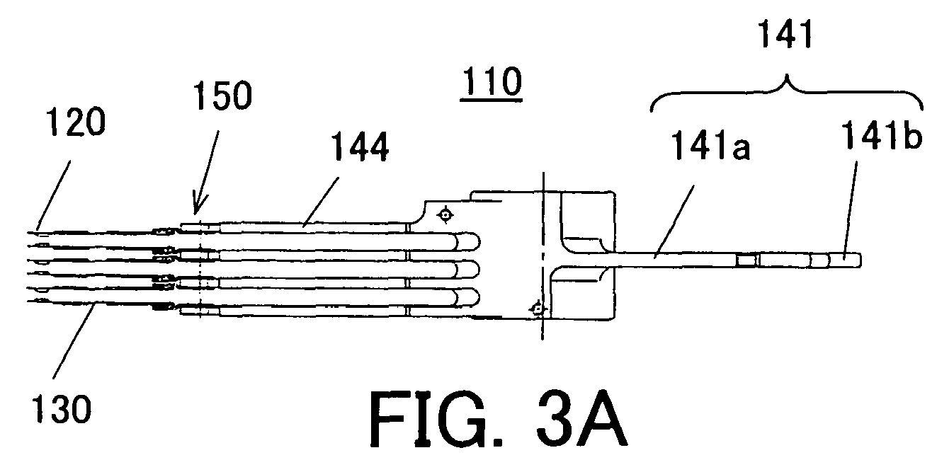
- FIGs. 3A to 3C are left side, plane and right side views, respectively, showing a detailed structure of a head stack assembly ("HSA") shown in FIG. 1.
- FIGs. 4A and 4B are schematic plane and sectional views of a suspension jointed with a base plate.
- FIGs. 5A and 5B are schematic plane and sectional views of the base plate shown in FIGs. 4A and 4B.
- FIG. 6 is a flowchart for explaining a manufacturing method of a structure shown in FIGs. 3A and 3C in which a pair of base plates are swaged with both sides of the arm.
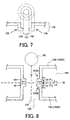
- FIG. 7 shows schematic plane and sectional views of a dent in the base plate shown in FIGs. 5A and 5B.
- FIG. 8 is a schematic sectional view for explaining swaging of the base plates shown in FIGs. 5A and 5B with both sides of the arm.
- FIGs. 9A to 9C are schematic sectional views of a previously-proposed structure that swags the base plates with both sides of the arm.
- FIGs. 10A and 10B are schematic sectional views of shapes of the base plates shown in FIG. 8.
- FIGs. 11 A to 11C are schematic sectional views of base plates according to Example 1 of the present invention.
- FIGs. 12A to 12C are schematic sectional views of a comparative example that includes the base plates swaged with both sides of the arm.
- FIG. 13 is a schematic sectional view of base plates according to Example 3 of the present invention.
- FIGs. 14A and 14B show graphs of results of Example 3.
- FIG. 15 is a schematic sectional view of a base plate according to Example 4 of the present invention.
- FIGs. 16A and 16B are graphs of results of Example 4.
- FIG. 17 is a graph of a result of Example 5.
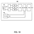
- FIG. 18 is a block diagram of a control system in the HDD shown in FIG. 1.
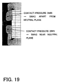
- FIG. 19 is a schematic sectional view of base plates according to Example 6 of the present invention after swaging.
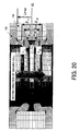
- FIG. 20 is a sectional view showing the extended sections of the base plates and the arm according to Example 7 of the present invention after swaging.
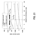
- FIG. 21 is a graph showing a relationship between a momental difference and warp amounts according to Example 7 of the present invention.
- FIG. 22 is a graph for explaining a momental balance improvement.
- FIG. 23 is a graph showing a relationship between a momental difference and warp amounts according to Example 7 of the present invention.
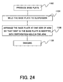
- FIG. 24 is a flowchart for explaining a manufacturing method of a structure shown in FIGs. 3A and 3C in which one base plate is swaged with one side of the arm.
- FIG. 25 is a schematic sectional view for explaining swaging of the base plates shown in FIGs. 5A and 5B with one side of the arm.
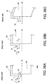
- FIGs. 26A to 26C are schematic sectional views of a comparative example that includes the base plates swaged with one side of the arm.
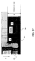
- FIG. 27 is a partially enlarged sectional view of the base plate swaged with the arm shown in FIG. 25.
- FIG. 28 is a graph showing a relationship among a distance between a swaging position on the base plate and the neutral plane in FIG. 27, and warp amounts.
- Referring now to the accompanying drawings, a description will be given of a
HDD 100 according to one embodiment of the present invention. TheHDD 100 includes, as shown in FIG. 1, pluralmagnetic discs 104 each serving as a recording medium, aspindle motor 106, and aHSA 110 in ahousing 102. Here, FIG. 1 is a schematic plane view of the internal structure of theHDD 100. - The housing is made, for example, of aluminum die cast base and stainless steel, and has a rectangular parallelepiped shape to which a cover (not shown) that seals the internal space is jointed. The
magnetic disc 104 of this embodiment has a high surface recording density, such as 100 Gb/in2 or greater. Themagnetic disc 104 is mounted on a spindle of thespindle motor 106 through its center hole of themagnetic disc 104. - The
spindle motor 106 rotates themagnetic disc 104 at such a high speed as 15,000 rpm, and has, for example, a brushless DC motor (not shown) and a spindle as its rotor part. For instance, twomagnetic discs 104 are used in order of the disc, a spacer, the disc and a clamp stacked on the spindle, and fixed by bolts coupled with the spindle. Unlike this embodiment, themagnetic disc 104 may be a disc that has no center hole but a hub, and the spindle rotates the disc via the hub. - The
HSA 100 includes amagnetic head part 120, asuspension 130, acarriage 140, and abase plate 150. - The
magnetic head 120 includes, as shown in FIG. 2, an approximately square, Al2O3 - TiC (Altic)slider 121, and a head device built-infilm 123 that is jointed with an air outflow end of theslider 121 and has a reading andrecording head 122. Here, FIG. 2 is an enlarged view of themagnetic head part 120. Theslider 121 and the head device built-infilm 123 define a medium opposing surface to themagnetic disc 104, i.e., a floatingsurface 124. The floatingsurface 124 receivesairflow 125 that occurs with rotations of themagnetic disc 104. - A pair of
rails 126 extend on the floatingsurface 124 from the air inflow end to the air outflow end. A top surface of eachrail 126 defines a so-called air-bearing surface ("ABS") 127. TheABS 127 generates the buoyancy due to actions of theairflow 125. Thehead 122 embedded into the head device built-infilm 123 exposes from theABS 127. The floating system of themagnetic head part 120 is not limited to this mode, and may use known dynamic and static pressure lubricating systems, piezoelectric control system, and other floating systems. The activation system may be a contact start stop ("CSS") system in which themagnetic head part 120 contacts thedisc 104 at the stop time, or a dynamic or ramp loading system in which themagnetic head part 120 is lifted up from thedisc 104 at the stop time and held on the ramp outside thedisc 104 while themagnetic head part 120 does not contact thedisc 104, and themagnetic head part 120 is dropped from the holding part to thedisc 104 at the start time. - The
head 122 is a MR inductive composite head that includes an inductive head device that writes binary information in themagnetic disc 104 utilizing the magnetic field generated by a conductive coil pattern (not shown), and a magnetoresistive ("MR") head that reads the binary information based on the resistance that varies in accordance with the magnetic field applied by themagnetic disc 104. A type of the MR head device is not limited, and may use a giant magnetoresistive ("GMR"), a CIP-GMR ("GMR") that utilizes a current in plane ("CIP"), a CPP-GMR that utilizes a perpendicular to plane ("CPP"), a tunneling magnetoresistive ("TMR"), an anisotropic magnetoresistive ("AMR"), etc. - The
suspension 130 serves to support themagnetic head part 120 and to apply an elastic force to themagnetic head part 120 against themagnetic disc 104, and is, for example, a Watlas type suspension made of stainless steel. This type of suspension has a flexure (also referred to as a gimbal spring or another name) which cantilevers themagnetic head part 120, and a load beam (also referred to as a load arm or another name) which is connected to the base plate. The load beam has a spring part at its center so as to apply a sufficient compression force in a Z direction. Therefore, the load beam includes a rigid part at its proximal end, a spring part at its center, and a rigid part at its distal end. The load beam contacts the flexure via a projection called a dimple (referred to as a pivot or another name) so that theABS 124 follows the disc's warp and swell and it is always parallel to the disc surface. Themagnetic head part 120 is designed to softly pitch and roll around the dimple. Thesuspension 130 also supports awiring part 138 that is connected to themagnetic head part 120 via a lead etc. Thewiring part 138 is shown in FIG. 4A, which will be described later. Via this lead, the sense current flows and read/write information is transmitted between thehead 122 and thewiring part 138. Thewiring part 138 is connected to a relay flexible circuit board ("FPC") 143 under thearm 144 shown in FIG. 3B. - As described later, this embodiment reduces the warp amount of the
base plate 150 and thus improves the flatnesses of thesuspension 130 and themagnetic head part 120, thereby preventing crushes and maintaining positioning accuracy due to excessive elastic force and torsion force. - The
carriage 140 serves to rotate themagnetic head part 120 in arrow directions shown in FIG. 1 and includes, as shown in FIGs. 1 and 3A to 3C, avoice coil motor 141, asupport shaft 142, aFPC 143, and anarm 144. Here, FIG. 3A is a left side view of theHSA 110. FIG 3B is a plane view of theHSA 110. FIG. 3C is a right side view of theHSA 110. While FIGs. 3A to 3C show thecarriage 140 that drives sixmagnetic head parts 120 that record and reproduce both sides of threediscs 104, the number of discs is, of course, not limited to three. - The
voice coil motor 141 has aflat coil 141b between a pair of yokes 141a. Theflat coil 141b opposes to a magnetic circuit (not shown) provided to thehousing 102 of theHDD 100, and thecarriage 140 swings around thesupport shaft 142 in accordance with values of the current that flows through theflat coil 141b. The magnetic circuit includes, for example, a permanent magnet fixed onto an iron plate fixed in thehousing 102, and a movable magnet fixed onto thecarriage 140. Thesupport shaft 142 is inserted into a hollow cylinder in thecarriage 140, and extends perpendicular to the paper surface of FIG. 1 in thehousing 102. TheFPC 143 provides thewiring part 138 with a control signal, a signal to be recorded in thedisc 104, and the power, and receives a signal reproduced from thedisc 104. - The
arm 144 is an aluminum rigid body that can rotate or swing around thesupport axis 142, and has aperforation hole 145 at its top, which will be described later. Thesuspension 130 is attached to thearm 144 via theperforation hole 145 in thearm 144 and thebase plate 150. Thearm 144 has a comb shape when viewed from a side as shown in FIGs. 3A and 3C. - The
base plate 150 serves to attach thesuspension 130 to thearm 144, and includes, as shown in FIGs. 4A to 5B, aplate section 151, a weldedsection 152, and a dent ordowel 154. The weldedportion 152 is a tip of theplate section 151 to be laser-welded with thesuspension 130. Thedent 154 is a part to be swaged with thearm 144. Here, FIG. 4A is a schematic plane view of thesuspension 130 jointed with thebase plate 150. FIG. 4B is a schematic sectional view of thatsuspension 130. FIG. 5A is a schematic plane view of thebase plate 150. FIG. 5B is a schematic sectional view of thebase plate 150. - Referring now to FIG. 6, a description will be given of connections between a
second arm 144 from the top in FIG. 3A and a pair ofbase plates 150. Thesecond arm 144 from the top in FIG. 3A has a double-head structure, in which thebase plates 150 are attached to both sides of thearm 144. Here, FIG. 6 is a flowchart for explaining connections between thearm 144 and thebase plates 150. - First, as shown in FIGs. 5A and 5B, the
base plate 150 is produced (step 1002).Step 1002 forms thedent 154 in theplate section 151 of thebase plate 150 by press work. Thedent 154 has an extended section orrim 156 and anopening 157. as shown in FIG. 7 at its top. Theextended section 156 and its vicinity form the L-shapedboss 155 that plastically deforms. Here, FIG. 7 is a schematic enlarged plane and sectional views of thebase plate 150. - Next, as shown in FIGs. 4A and 4B, the welded
section 152 of thebase plate 150 is laser-welded with the suspension 130 (step 1004). Themagnetic head part 120 is attached to thesuspension 130 before or afterstep 1004. - Next, as shown in FIG. 8, the
base plate 150 is arranged at both sides of thearm 144 so that thedent 152 of eachbase plate 150 is inserted into theperforation hole 145 of the arm 144 (step 1006). Here, FIG. 8 shows a pair ofbase plates 150 engaged with both sides of thearm 144. Next, swaging follows (step 1008). The swaging passes aswaging ball 50 whose diameter is slightly greater than a diameter of theopening 157, in one direction shown by an arrow through theperforation hole 145. As a result, theboss 155 of thebase plate 150 crushes and plastically deforms as shown by horizontal arrows in FIG. 8, thereby jointing thebase plates 150 with thearm 144. As shown by an alternate long and short dash line in FIG. 8, a surface that halves the thickness of thearm 144, and is perpendicular to the center axis CA of theperforation hole 145 is referred to as a neutral plane IS. - The instant inventors have discovered that the previously-proposed upper and lower base plates when arranged as shown in FIG. 8 warp upwardly because the base plate's deformation is influenced not only by the base plate's own deformation due to the plastic deformation force by the
ball 50 but also by thearm 144's deformation. - FIG. 9A exaggerates shapes of the previously-proposed
base plates base plates arm 144 before swaging. A position or power point P2 at which theball 50 first contacts theupper base plate 30A is located above a position or fulcrum P1 at which thebase plate 30A contacts thearm 144, i.e., the fulcrum P1 is located closer to the neutral plane IS than the power point P2. This is because when the power point P2 is closer to the neutral plane IS than the fulcrum P1, an upperextended section 32A is likely to deform in the counterclockwise arrow direction rather than against thearm 144 as theball 50 passes. When the deformation force applied by theball 50 is consumed for the downward deformation of anextended section 32A and the horizontal deformation reduces, the jointing force or contact pressure applied by aboss 31A to thearm 144 undesirably weakens, and thebase plate 30A is likely to drop off from thearm 144. For similar reasons, a position or power point P4 at which theball 50 first contacts thelower base plate 30B is located under a position or fulcrum P3 at which thebase plate 30B contacts thearm 144, i.e., the fulcrum P3 is located closer to the neutral plane IS than the power point P4. - Next, the
upper base plate 30A has aboss 31A with an L-shaped section, whereas thelower base plate 30B has aboss 31 B with a reverse L-shaped section. As simply shown in FIG. 9B, when the L-shapedboss 31A and the reverse L-shapedboss 31 B receive a perpendicularly downward force from theball 50, both thebosses - In this case, a force F1 that opens the L-shape is smaller than a force F2 that closes the L-shape. While the
ball 50 moves downwardly, theboss 31 A needs a smaller force F1 whereas theboss 31B needs a larger force F2. This relationship is true of the contact pressure as a horizontal force: A contact pressure F3 applied from theboss 31 A to thearm 144 is smaller than a contact pressure F4 applied from theboss 31 B to thearm 144. - From the relationship between the contact pressures F3 and F4 around the neutral plane IS, the
arm 144 receives the counterclockwise moment in FIG. 9B, and deforms upwardly in FIG. 9C. Here, FIG. 9C is a partial enlarged sectional view showing deformations of the base plates and the arm after swaging. Thebase plates arm 144. Theupper arm 144 restricts the deformation of thebase plate 30B, whereas there is no member that restricts the upper deformations of thebase plate 30A, and thebase plate 30A more greatly deforms upwardly. After swaging, the extended section of thebase plate 30A is closer to the neutral plane IS than that of thebase plate 30B. This results from the deformations of thebase plates arm 144's deformation, and thebase plates extended sections base plates arm 144's deformation. - In order to reduce the deformations of the
base plates arm 144, the instant inventors have first studied a reduction of a difference between the contact pressures F3 and F4 in FIG. 9B. When the difference between the contact pressures F3 and F4 becomes smaller, the moment applied to thearm 144 becomes smaller and the deformations become smaller. - In order to reduce the deformations of the
base plates arm 144, the instant inventors have next studied a structure in which the moments around the neutral plane IS applied from the upper andlower base plates 150A an 150B to thearm 144 cancel each other as completely as possible. In other words, in FIG. 8, this embodiment changes shapes and arrangements of the upper andlower base plates boss 155A of thebase plate 150A to thearm 144 around the neutral plane IS is approximately equal to a moment M2 = F22 x L22 applied from the boss 155B of thebase plate 150B to thearm 144 around the neutral plane IS, where F11 is a contact pressure applied from theboss 155A of thebase plate 150A to thearm 144, L11 is a distance between the point P11 to which the contact pressure F11 is applied and the neutral plane IS, F22 is a contact pressure applied from the boss of thebase plate 150B to thearm 144, and L22 is a distance between the point P22 to which the contact pressure F22 is applied and the neutral plane IS. In order to make M1 and M2 approximately equal to each other where thebase plate 150A is fixed, F22 and/or L22 of thebase plate 150B need to be adjusted. In case where L11 = L22, a difference between F11 and F22 may be reduced. Thereby, the moment applied to thearm 144 reduces, and its deformation reduces. For example, a reduction of a difference between the contact pressures F3 and F4 will be attempted in FIG. 9B. - The difference between the contact pressures F3 and F4 in FIG. 9B attributes to a fact that the
extended section 32A of theupper base plate 30A deforms outwardly (or in the L-shape opening direction) while theextended section 32B of thelower base plate 30B deforms inwardly (or in the L-shape closing direction): In other words, the upper and lowerextended sections - Accordingly, in principle, this embodiment inverts a positional relationship between the positions P1 and P2 and a positional relationship between the positions P3 and P4 in FIG. 9A to those shown in FIG. 10A. Here, FIG. 10A is a schematic view of the
base plates base plate 150 having the structure shown in FIG. 10A, for example, an inclined surface is formed on a lower mold that forms a bottom surface of theextended section 156 of thebase plate 150 in the mold of the pressing machine for use withstep 1002. - With such an arrangement when the power points P2' and P4' receive horizontal forces from the
ball 50, theextended section 156A of theupper base plate 150A and theextended section 156B of thelower base plate 150B deform in the same direction (or in the L-shape opening direction), and their resistances to theball 50 become almost equal to each other. As a result, the difference between the contact pressure F11 applied from theboss 155A of theupper base plate 150A to thearm 144 and the contact pressure F22 applied from the boss 155B of theupper base plate 150B to thearm 144 reduces in FIG. 8. As a result, the deformation of thearm 144 reduces, and the warps of thebase plates suspensions 130 connected to them reduce. - As discussed above, when the power points P2' and P4' are arranged closer to the neutral plane IS than the fulcrums P1' and P3', the contact pressures applied from the
bosses 155A and 155B to thearm 144 reduce. However, it is preferable for the precise positioning of the head 122.to maintain the flatness of thesuspension 130 even when the contact pressure is slightly sacrificed. Nevertheless, if the contact pressure is excessively low, thesuspension 130 is likely to disengage from thearm 144 and the vibration tolerance deteriorates. Therefore, this embodiment provides a predetermined lower limit, as described later. - In addition to the structure of FIG. 10A, the influence on the
suspension 130 of the base plates' own deformations caused by theball 50 can be limited by making, as shown in FIG. 10B, a minimum thickness T2 within theperforation hole 145 smaller than an original thickness T1 of thebase plates perforation hole 145. Here, FIG. 10B is a schematic enlarged sectional view as a variation of FIG. 10A. - A pair of
base plates base plates - In FIG. 8, when L11 is different from L22, L22 and/or F22 may be adjusted so as to make M1 and M2 equal to each other, for example, by reducing L22 so that P22 approaches to the neutral plane IS or by enlarging the minimum diameter of the boss 155B and reducing F22. In this embodiment, the
base plates - The previously-proposed
base plates - The contact pressures in FIGs. 11B and 12B are calculated: According to this embodiment, the upper contact pressure is 210 N and the lower contact pressure is 240 N as shown in FIG. 11C. According to the comparative example, the upper contact pressure is 220 N and the lower contact pressure is 266 N as shown in FIG. 12C. This embodiment is well-balanced between the upper and lower contact pressures, and has a warp amount reducing effect of about 40 %.
- In Example 1, after swaging shown in FIGs. 11B and 11C, distances from the
base plates base plates arm 144 and the closest points of thebase plates base plates arm 144 reduces. On the other hand, in the comparative example shown in FIGs. 12B and 12C, with respect to distances from eachbase plate 30 to the neutral plane IS, the larger distance is three times as large as the smaller distance or greater. - An alternative example makes the upper base plate like a comparative example, and the lower base plate like this embodiment. As a result, the upper contact pressure is 220 N and the lower contact pressure becomes 240 N, and the contact pressure difference reduces further.
- In the structure of Example 1, the thickness T2 is made half the thickness T1 as shown in FIG. 10B, and a relationship between the warp amounts of the base plates and the displacement of the arm is studied. Table 1 shows results of comparative example and Examples 1 and 2. In Table 1, a upper displacement is set plus, and UP in the "position" section means the
upper base plate lower base plate 150B (or 150D).TABLE 1 POSITION WARP AMOUNT [µm] ARM'S DISPLACEMENT [µm] COMPARATIVE EXAMPLE UP 12.20 3.98 DN -0.70 EXAMPLE 1 UP 7.8 2.26 DN -3.1 EXAMPLE 2 UP 6.10 2.32 DN -1.30 - As shown in FIG. 13, a line is drawn from the fulcrum P1' parallel to the neutral plane IS and an angle θ is defined as an angle between this line and a line that connects the fulcrum P1' and the power point P2' to each other in the
upper base plate 150A. Here, FIG. 13 is a section that includes the central axis (not shown) of theperforation hole 145 before swaging. The power points P2' and P4' are farthest from the neutral plane IS among positions having the smallest internal diameter on thebase plates base plate arm 144. - Similarly, a line is drawn from the fulcrum P3' parallel to the neutral plane IS and an angle θ is defined as an angle between this line and a line that connects the fulcrum P3' and the power point P4' to each other in the
lower base plate 150B. In FIG. 13, the power points P2' and P4' project when viewed from theball 50, and each can be regarded as a point. The clockwise direction is positive for θ in theupper base plate 150A, and the counterclockwise direction is positive for θ in thelower base plate 150B. By changing θ, the warp amounts of thebase plates arm 144, the upper and lower contact pressures, and a difference between these contact pressures are studied, and the results are summarized in FIGs. 14A and 14B. - It is understood from FIG. 14A that the
arm 144 has an approximately constant warp amount in a range -17° ≦ θ ≦ 5°, but -17° ≦ θ ≦ 0° is preferable since θ is preferably equal to or smaller than 0. However, the warp amounts of the upper and lower base plates and a difference between the lower and upper contact pressures remarkably vary in the range of θ ≦ -12°, -12° ≦ θ ≦ 0° is more preferable. - In addition, when the stable contact pressure between the
base plate 150 and thearm 144 is defined as 200 N, the upper contact pressure becomes 200 N or smaller in the range of θ ≦ -12° and thus -12° ≦ θ is preferable. - This example is similar to Example 3 shown in FIG. 13, but different in that a surface has the smallest internal diameter as shown in FIG. 15 and the area having the smallest internal diameter is wider. This example has plural points having the smallest internal diameter in the
base plates base plates arm 144, the upper and lower contact pressures, and a difference between these contact pressures are studied, and the results are summarized as shown in FIGs. 16A and 16B. The angle θ' have the same positive and negative directions as the angle θ. - It is understood from FIG. 16A that the
arm 144 has an approximately constant warp amount in a range -10° ≦ θ' ≦ 10°, but -10° ≦ θ' ≦ 0° is preferable since θ' is preferably equal to or smaller than 0. However, the warp amounts of the upper and lower base plates and a difference between the lower and upper contact pressures remarkably vary in the ranges of θ ≦ -5° and 5° ≦ θ', -5° ≦ θ ≦ 5° is more preferable but -5° ≦ θ' ≦ 0° is most preferable since θ' is preferably equal to or smaller than 0. - In addition, when the stable contact pressure between the
base plate 150 and thearm 144 is defined as 200 N, the upper contact pressure becomes 200 N or smaller in the range of θ ≦ -5° and thus -5° ≦ θ is preferable. - The thickness T2 and a ratio between the thickness T1 and the thickness T2 are varied in the structure shown in FIG. 10B, and the warp amounts of the
base plates arm 144 are studied. The results are summarized as shown in FIGs. 17A and 17B. The warp amount of theupper base plate 150C and the warp amount of thelower base plate 150D are a sum of the warp amounts of the base plates and the warp amount of the arm. As the thickness T2 increases, the warp amount decreases since the warp amount of the base plates themselves reduce. However, as the thickness T2 increases, the warp amount of thearm 144 increases. Therefore, the total warp amounts of thebase plates 150 resultantly have an extreme point. Referring to FIG. 17A, the total warp amount becomes smallest when the thickness T2 is 0.1 mm (50 % of the thickness T1). From FIGs. 17A and 17B, 0.12 mm ≦ T2 ≦ 0.07 mm is preferable, but when the manufacturing errors are considered, 0.08 mm ≦ T2 ≦ 0.12 mm is more preferable. 35 % ≦ T2 / T1 ≦ 60 % is preferable, but when the manufacturing errors are considered, 40 % ≦ T2 / T1 ≦ 60 % is more preferable. - This example, unlike
Japanese Patent Application, Publication No. 7-192420 perforation hole 145 instead of arranging the thin-walled section on thearm 144. When the thin-walled section is arranged on thearm 144 as inJapanese Patent Application, Publication No. 7-192420 lower base plate 150B excessively deforms downwardly especially at the calking time. Accordingly, this example arranges the thin-walled section having the thickness T2 within theperforation hole 145, maintains the flatness of thelower base plate 150B, and prevents the influence of the deformation of the base plate on thesuspension 130 during swaging. - The thickness T2 of the boss does not greatly change in the
perforation hole 145 before and after swaging. Thus, if T2 and T2 / T1 after swaging satisfy the above conditions, that configuration can be considered to exhibit the operation of the manufacturing method of this embodiment. - The comparative example uses the configuration shown in FIGs. 12A and 12B before swaging, whereas this example uses a pair of differently shaped base plates in which the upper base plate has a shallower dent and the lower base plate has a deeper dent than those of the comparative example. This example corresponds to FIG. 8 in which L11 is made larger and L22 is made smaller. Similar to Example 1, a shape shown in FIG. 19 is obtained through simulation that utilizes the FEM by swaging the upper and lower base plates.
- As shown in FIG. 19, the upper contact pressure is 244 N and the lower contact pressure is 284 N in this example, whereas the upper contact pressure is 220 N and the lower contact pressure is 266 N in the comparative example. While the contact-pressure difference does not greatly differ between this example and the comparative example, this example keeps the swaged position of the upper base plate (corresponding to P11 in FIG. 8) away from the neutral place IS and puts the swaged position of the lower base plate (corresponding to P22 in FIG. 8) close to the neutral plane IS. Therefore, as shown in Table 2 below, the arm's warp amount reduces by 70 %. Of course, the contact pressure may also be varied with or instead of a distance from the neutral plane IS. As discussed above, the contact pressure is adjustable, for example, by making the minimum diameter within the
perforation hole 145 of the lower base plate smaller than that of the upper base plate, or by forming a boss shape having the same positional relationship among P3', P4' and the neutral plane.TABLE 2 POSITION BEND [um] ARM'S DISPLACEMENT [µm] COMPARATIVE EXAMPLE UP 12.20 3.98 DN -0.70 EXAMPLE 6 UP 3.61 1.02 DN 4.82 - A surface contact between the
base plate 150 and thearm 144 will be studied in detail. FIG. 20 shows states of the extended section of the base plates and thearm 144 after swaging. Suppose that F denotes a contact pressure generated during swaging, F11 denotes the contact pressure of the upstream (or upper) base plate, and F22 denotes the contact pressure of the downstream (or lower) base plate along theball 50's moving direction. Thebase plate 150 contacts theball 50 over a range from α to β. An apparent swaging position is defined as an intermediate value of the contact surface between the ball and the boss (or the swaging position L = (α + β) / 2). L11 denotes a swaging position of the upstream (or upper) base plate, and L22 denotes a swaging position of the downstream (or lower) base plate. In FIG. 20, L11 = L22 is met. The contact pressure meets F11 < F22. In this case, the moment M given by L x F meets M11 < M22. Due to this momental unbalance, the arm inclines and the warp amount of the base plate increases. Theoretically, when this phenomenon is considered strictly, the contact pressure is uneven over the contact surface and the moment applied to the arm should be calculated through integration over the contact area. Nevertheless, it is permissible to simply consider the contact pressure constant and evaluate the momental difference using the above approach. The warp amounts of the arm and the base plates can be reduced by improving the momental unbalance. - FIG. 21 shows a warp-amount improvement effect by changing the swaging position L in the upstream and downstream base plates. In FIG. 21, the abscissa axis denotes the momental difference M2 - M1 and the warp amounts of the arm and the base plates are evaluated relative to the momental difference. L11 = L22 is met at a position where the momental difference is 10 N·mm in FIG. 21. As described above, since F11 < F22, the lower moment increases and the arm has a warp amount. On the other hand, when L11 < L22, the momental difference increases and the warp amounts of the arm and the upper and lower base plates increase.
- When L11 > L22, the momental difference reduces and the warp amounts of the arm and the upper and lower base plates decrease. It is clear that M11 = M22 provides the best solution. L22 /L11 is an inverse number of F22 / F11 when M11 = M22 is met. Where L11opt and L22opt denote the best combination of L, 0 < L11 < Lmax and 0 < L22 < Lmax are met in the swaged structure in which L11 > L22. A combination of L11 and L22 that satisfies F11 / F22 x 0.8 ≦ L22 / L11≦ F11 / F22 x 1.2 is preferable. Alternatively, L11opt - 0.02 mm ≦ L11 ≦ L11opt + 0.02 mm and L22opt - 0.02 mm ≦ L22 ≦ L22opt + 0.02 mm are preferable, or L11opt x 0.8 ≦ L11 ≦L11opt x 1.2 and L22opt x 0.8 ≦ L22 ≦ L22opt x 1.2 are preferable.
- Referring to FIG. 22, the contact pressure may be increased in order to improve the momental balance. The swaging margin is expressed by δ1 = Φ1 -Φb and δ2 = Φ2 -Φb, where Φ1 and Φ2 denote the minimum internal diameter of the extended section of the base plates, and Φb denotes a diameter of the ball. As the swaging margin is greater, the contact pressure increases accordingly. In addition, V 1 and V2 are defined as volumes of the
base plates 150 inside the diameter Φb of theswaging ball 50. The swaging force increases by increasing these volumes. - FIG. 23 is a graph having the abscissa axis of a momental difference M22 - M11, and evaluates the warp amounts of the
arm 144 and thebase plates 150 relative to the momental difference when Φ1 and Φ2 are varied. Even when the swaging margin is made constant, due to the swaging difference between the upper and lower base plates, the contact pressure meets F11 < F22. Therefore, the moment of the lower base plate is larger and thearm 144 has a warp amount. When Φ1 < Φ2, the momental difference expands and the warp amounts of thearm 144 and the upper and lower base plates increase. When Φ1 > Φ2, the momental difference reduces and the warp amounts of thearm 144 and the upper and lower base plates decrease. When both moments are balanced, the arm's deformation becomes minimum. Suppose that the best combination of δ that gives F11 = F22 are δ1opt and δ2opt. A similar effect of varying the contact pressure is obtained by making V1 > V2. A similar effect is obtained by combining L11 > L22. - In summary, Φ1 > Φ2 is preferable. More preferably, δ1opt - 0.02 mm < δ1 < δ1opt + 0.02 mm and δ2opt - 0.02 mm < δ2 < δ2opt + 0.02 mm or δ1opt x 0.8 < δ1 < δ1opt x 1.2 and δ2opt x 0.8 < δ2 < δ2opt x 1.2 are met.
- Alternatively, V1 > V2 is preferable. More preferably, V1opt x 0.2 < V1 < V1opt x 1.2 and V2opt x 0.2 < V2 < V2opt x 1.2 are met. Combinations of δ1 > δ2 and L1 > L2, V1 > V2 and L1> L2, δ1 > δ2 and V1> V2 and δ1 > δ2, L1> L2 and V1> V2 are also preferable.
- Referring now to FIG. 24, a description will be given of a connection between a
fourth arm 144 from the top in FIG. 3A and thebase plate 150. Thefourth arm 144 from the top in FIG. 3A has a single head structure, in which onebase plate 150 is attached to one side of thearm 144. Here, FIG. 24 is a flowchart for explaining a connection between thearm 144 and thebase plate 150. - First, as shown in FIGs. 5A and 5B, the
base plate 150 is produced (step 1102). Similar to step 1002,step 1102 forms thedent 154 in theplate section 151 of thebase plate 150 by press work, as shown in FIG. 7. The depth of thedent 154 or the position of theboss 155 is set from a relationship between the neutral plane IS and a swaging position, which will be described below. - Next, similar to step 1004, as shown in FIGs. 4A and 4B, the welded
section 152 of thebase plate 150 is laser-welded with the suspension 130 (step 1104). Themagnetic head part 120 is attached to thesuspension 130 before or afterstep 1104. - Next, as shown in FIG. 25, the
base plate 150 is arranged at one side of thearm 144 so that thedent 152 of thebase plate 150 is inserted into theperforation hole 145 of the arm 144 (step 1106). Here, FIG. 25 shows that thebase plate 150 is inserted into one side of thearm 144. This embodiment sets the depth of thedent 154 so that the swaging position of thebase plate 150 accords approximately with the neutral plane IS. - Next, swaging follows (step 1108). The swaging passes a
swaging ball 50 whose diameter is slightly greater than a diameter of theopening 157, in one direction shown by an arrow through theperforation hole 145, as shown in FIG. 25. As a result, theboss 155 of thebase plate 150 crushes and plastically deforms as shown by a horizontal arrow in FIG. 25, thereby jointing thebase plate 150 with thearm 144. - The instant inventors have discovered that the previously-proposed base plate warps downwardly because the deformation of the base plate is influenced not only by the
base plate 150's own deformation due to the plastic deformation force by theball 50 but also by the deformation of thearm 144. - FIG. 26A exaggerates a shape of the previously-proposed
base plate 30. More specifically, FIG. 26A is a partially enlarged sectional view of an arrangement between the previously-proposedbase plate 30 and thearm 144 before swaging. A position or power point P2 at which theball 50 first contacts theupper base plate 30 is located above a position or fulcrum P1 at which thebase plate 30A contacts thearm 144, i.e., the fulcrum P1 is located closer to the neutral plane IS than the power point P2. This is because when the power point P2 is closer to the neutral plane IS than the fulcrum P1, the upperextended section 32 is likely to deform in the counterclockwise arrow direction rather than against thearm 144 as theball 50 passes. When the deformation force applied by theball 50 is consumed for the downward deformation of anextended section 32 and the horizontal deformation reduces, the jointing force or contact pressure applied by aboss 31 to thearm 144 undesirably weakens, and thebase plate 30A is likely to separate from thearm 144. - As simply shown in FIG. 26B, when the
boss 31 receives a perpendicularly downward force F1 from theball 50, theboss 31 deforms both downwardly and horizontally. In addition, a contact pressure F3 applies to thearm 144 from theboss 31. Here, FIG. 26B is a partial enlarged sectional view showing the forces applied to thebase plate 30 due to swaging and the amount of the contact pressure to thearm 144 from thebase plate 30. - From the contact pressure F3 around the neutral plane IS, the
arm 144 receives the counterclockwise moment in FIG. 26B, and deforms downwardly as shown in FIG. 26C. Thebase plate 30 follows thearm 144 and deforms downwardly. This deformation of thearm 30 is caused by thearm 144. Thebase plate 30 itself deforms due to itsextended section 32 caused by the force F1. As a result, the deformation of thebase plate 30 is a superposition between its own deformation and the deformation caused by thearm 144. Here, FIG. 26C is a partial enlarged sectional view showing deformations of thebase plate 30 and thearm 144 after swaging. - In order to reduce the deformation of the
base plate 30 due to the deformation of thearm 144, the instant inventors have studied a structure that minimizes the moment applied to thearm 144 around the neutral plane IS. In other words, in FIG. 25, this embodiment sets L11 to approximately zero and zeros a moment M1 = F11 x L11 applied from theboss 155 of thebase plate 150 to thearm 144 around the neutral plane IS, where F11 is a contact pressure applied from theboss 155 of thebase plate 150 to thearm 144, and L11 is a distance between the swaging point P11 to which the contact pressure F11 is applied and the neutral plane IS. Thereby, the moment applied to thearm 144 becomes zero, and thearm 144's deformation becomes small. - However, as shown in FIG. 27, the
base plate 150 can be swaged with thearm 144 through its surface. Here, FIG. 27 is a partial enlarged sectional view of thebase plate 150 swaged with thearm 144, with respect to a section that includes a center axis of theperforation hole 145 of thearm 144. The swaging position P11 is an intermediate position between the most upstream position α and the most downstream position β along the swaging direction C (or moving direction of the swaging ball 50) among contact positions between thebase plate 150 and thearm 144. - FIG. 28 shows a relationship between the swaging position from the neutral plane and the warp amount. From FIG. 28, when the swaging position accords with the neutral plane, the warp amounts of the
arm 144 and thebase plate 150 become minimum. As shown in FIG. 27, the contact surface between theboss 155 and thearm 144 crosses the neutral plane IS over the position α and the position βin this embodiment. The arm has a thickness of 0.048 mm in FIG. 27 in this embodiment. From FIG. 28, when the swaging position is set in a range of ±0.05 mm from the neutral plane IS, the warp amount is maintained to be a permissible range of about ±0.01 mm. The range of ±0.05 mm corresponds to a range of about ±10 % of the thickness of the arm (±0.048 mm). However, when the manufacturing errors of thebase plate 150 are considered, the swaging position is preferably set in a range of about ±5 % of the thickness of the arm (±0.024 mm). - While the above embodiment describes the single head structure in the
fourth arm 144 from the top in FIG. 3A, the above is true of thetop arm 144 in FIG. 3A. - FIG. 18 shows a control block diagram of a
control system 160 in theHDD 100. Thecontrol system 160 is a control illustration in which thehead 122 has a inductive head and an MR head. Thecontrol system 160, which can be implemented as a control board in theHDD 100, includes acontroller 161, aninterface 162, a hard disc controller (referred to as "HDC" hereinafter) 163, awrite modulator 164, aread demodulator 165, a sense-current controller 166, and ahead IC 167. Of course, they are not necessarily integrated into one unit; for example, only thehead IC 167 is connected to thecarriage 140. - The
controller 161 covers any processor such as a CPU and MPU irrespective of its name, and controls each part in thecontrol system 160. Theinterface 162 connects theHDD 100 to an external apparatus, such as a personal computer ("PC" hereinafter) as a host. TheHDC 163 sends to thecontroller 161 data that has been demodulated by theread demodulator 165, sends data to thewrite modulator 164, and sends to the sense-current controller 166 a current value as set by thecontroller 161. Although FIG. 18 shows that thecontroller 161 provides servo control over thespindle motor 106 and (a motor in) thecarriage 140, theHDC 163 may serve as such servo control. - The
write modulator 164 modulates data and supplies data to thehead IC 162, which data has been supplied, for example, from the host through theinterface 162 and is to be written down onto thedisc 104 by the inductive head. Theread demodulator 165 demodulates data into an original signal by sampling data read from thedisc 104 by the MR head device. Thewrite modulator 164 and readdemodulator 165 may be recognized as one integrated signal processing part. Thehead IC 167 serves as a preamplifier. Each part may apply any structure known in the art, and a detailed description thereof will be omitted. - In operation of the
HDD 100, thecontroller 161 drives thespindle motor 106 and rotates thedisc 104. The airflow associated with the rotation of thedisc 104 is introduced between thedisc 104 andslider 121, forming a minute air film and thus generating the buoyancy that enables theslider 121 to float over the disc surface. Thesuspension 130 applies an elastic compression force to theslider 121 in a direction opposing to the buoyancy of theslider 121. The balance between the buoyancy and the elastic force spaces themagnetic head part 120 from thedisc 104 by a constant distance. As discussed above, the warp amount of thebase frame 150 is restrained, and the elastic compression force applied from thesuspension 130 and orientation, flying height and vibration tolerance etc. of theslider 121 are close to the designed values. Therefore, highly precise positioning of thehead 122 is available while the crushes are prevented. - The
controller 161 then controls thecarriage 140 and rotates thecarriage 140 around thesupport shaft 142 forhead 122's seek for a target track on thedisc 104. While this embodiment thus uses a swing arm type in which theslider 121 draws an arc locus around thesupport shaft 142, the present invention is applicable to a linear type in which theslider 121 draws a linear locus. - In writing, the
controller 161 receives data from the host (not shown) such as a PC through theinterface 162, selects the inductive head device, and sends data to thewrite modulator 164 through theHDC 163. In response, thewrite modulator 164 modulates the data, and sends the modulated data to thehead IC 167. Thehead IC 167 amplifies the modulated data, and then supplies the data as write current to the inductive head device. Thereby, the inductive head device writes down the data onto the target track. - In reading, the
controller 161 selects the MR head device, and sends the predetermined sense current to the sense-current controller 166 through theHDC 163. In response, the sense-current controller 166 supplies the sense current to the MR head device through thehead IC 167. Thereby, the MR head reads desired information from the desired track on thedisc 104. - Data is amplified by the
head IC 167 based on the electric resistance of the MR head device varying according to a signal magnetic field, and then supplied to theread demodulator 165 to be demodulated to an original signal. The demodulated signal is sent to the host (not shown) through theHDC 163,controller 161, andinterface 162. - Thus, the above embodiments can provide a HSA, its manufacturing method, and a magnetic disc having the HSA, which effectively restrain the deformation of the arm, and/or which effectively restrain the deformation of the base plate itself due to swag.
- Further, the present invention is not limited to these preferred embodiments, and various modifications and variations may be made without departing from the spirit and scope of the present invention. For example, while the above embodiments discuss the HDD, the present invention is applicable to other types of magnetic disc drives, such as a photo-magnetic disc drive.
Claims (28)
- A method for manufacturing a head stack assembly (110)that includes a pair of suspensions (130) each of which supports a head (122), an arm (144) that drives the head, and a pair of base plates (150) that attach the pair of suspensions to both sides of the arm that has a perforation hole (145), each of the pair of base plates having a boss (155) with an opening (157), said method comprising the step of swaging the pair of base plates with the arm by passing, in one direction, a processing member (50) larger than the opening through the perforation hole and the base plates while the pair of base plates are being inserted into the perforation hole at both sides of the perforation hole,
characterized in that where a neutral plane is defined as a plane that halves a thickness of the arm and is perpendicular to a section that includes a center axis of the perforation hole, a first position is defined as a position that has a minimum internal diameter of the base plate, and a second position is defined as a position closest to the neutral plane among contact positions between the base plates and the arm, a distance between the neutral plane and the first position is equal to or smaller than a distance between the neutral plane and the second position before said swaging step. - A method according to claim 1, wherein the first position is defined as an intermediate position between the farthest position from the neutral plane and the closest position to the neutral plane among positions that have the minimum internal diameter where the positions have the minimum internal diameter of the base plate form a surface.
- A method according to claim 1 or 2, wherein θ satisfies the following equation:

where θ is an angle between a line that passes the second position on the section where a direction going away from the neutral plane is positive and is parallel to the neutral plane, and a line that connects the first and second positions to each other. - A method according to claim 1 or 2, wherein θ satisfies the following equation:

where θ is an angle between a line that passes the second position on the section where a direction going away from the neutral plane is positive and is parallel to the neutral plane, and a line that connects the first and second positions to each other. - A method according to any preceding claim, wherein the base plate among the pair of base plates, which is located downstream along the one direction, deforms in an upstream direction along the one direction during said swaging step.
- A method according to any preceding claim, wherein the pair of base plates have the same shape before said swaging step.
- A head stack assembly (110) that includes a pair of suspensions (130) each of which supports a head (122), an arm (144) that drives the head and has a perforation hole (145), and a pair of base plates (150), swaged with both sides of the perforation hole of said arm, which attach said pair of suspensions to both sides of said arm,
characterized in that a larger distance between the closest points of said pair of base plates to a neutral plane that halves a thickness of said arm, and the closest position to the neutral plane among contact positions between said base plates and said arm is 130 % of a smaller distance or smaller. - A head stack assembly according to claim 7, wherein the larger distance is 115 % of the smaller distance or smaller.
- A method for manufacturing a head stack assembly (110) that includes a suspension (130) that supports a head (122), an arm (144) that drives the head, and a base plate (150) that has a boss (155) with an opening (157) and attaches the suspension to the arm that has a perforation hole (145), the base plate, said method comprising the step of swaging the pair of base plates with the arm by passing, in one direction, a processing member (50) larger than the opening through the perforation hole and the base plate while the base plate is being inserted into the perforation hole,
characterized in that the smallest thickness of the boss perpendicular to the one direction within the perforation hole is 60 % or smaller of a thickness of the base plate outside the perforation hole in a section that includes a center axis of the perforation hole before said swaging step. - A method according to claim 9, wherein the smallest thickness of the boss perpendicular to the one direction within the perforation hole is 35 % or greater of the thickness of the base plate outside the perforation hole.
- A method according to claim 9, wherein the smallest thickness of the boss perpendicular to the one direction within the perforation hole is 40 % or greater of the thickness of the base plate outside the perforation hole.
- A method according to claim 9, wherein the smallest thickness of the boss in the perforation hole is about 50 % of the thickness of the base plate outside the perforation hole or greater.
- A method according to any one of claims 9 to 12, wherein where a neutral plane is defined as a plane that halves a thickness of the arm and is perpendicular to the section, a first position is defined as a position that has a minimum internal diameter of the base plate and is farthest from the neutral position, and a second position is defined as a position that is closest to the neutral plane among contact positions between the base plate and the arm, a distance between the neutral plane and the first position is smaller than a distance between the neutral plane and the second position before said swaging step.
- A head stack assembly (110) that includes a suspension (130) that supports a head (122), an arm (144) that drives the head and has a perforation hole (145), and a base plate (150), swaged onto the perforation hole of said arm, which that has a boss (155) with an opening (157) and attaches the suspension to said arm,
characterized in that in a section that includes a center axis of said perforation hole, the smallest thickness of the boss perpendicular to the center axis within the perforation hole is 60 % of a thickness of said base plate outside the perforation hole or smaller. - A head stack assembly according to claim 14, wherein the smallest thickness of the boss perpendicular to the center axis within the perforation hole is 35 % or greater of the thickness of the base plate outside the perforation hole.
- A head stack assembly according to claim 14, wherein the smallest thickness of the boss perpendicular to the center axis within the perforation hole is 40 % or greater of the thickness of the base plate outside the perforation hole.
- A method for manufacturing a head stack assembly (110) that includes a pair of suspensions (130) each of which supports a head (122), an arm (144) that drives the head, and a pair of base plates (150) that attach the pair of suspensions to both sides of the arm that has a perforation hole (145), each of the pair of base plates having a boss (155) with an opening (157), said method comprising the step of swaging the pair of base plates with the arm by passing, in one direction, a processing member (50) larger than the opening through the perforation hole and the base plates while the pair of base plates are being inserted into the perforation hole at both sides of the perforation hole,
characterized in that where a neutral plane is defined as a plane that halves a thickness of the arm, a moment around the neutral plane applied from the pair of base plates to the arm after said swaging step is smaller than a moment around the neutral plane applied to the arm from a structure that has arranged an upstream base plate among the pair of base plates along the one direction symmetrically with respect to the neutral plane instead of a downstream base plate and has been swaged by the processing member. - A method according to claim 17, wherein the smallest internal diameter of the upstream base plate among the pair of base plates is smaller than the smallest internal diameter of the downstream base plate before said swaging step.
- A method according to claim 17 or 18, wherein before said swaging step, in a section that includes a center axis of the perforation hole, where a first position is defined as a position on the base plate which first contacts the processing member, and a second position is defined as one of contact positions between the base plate and the arm, the second position is closer to the neutral plane than the first position on the upstream base plate and the first position is closer to the neutral plane than the second position on the downstream base plate.
- A method according to claim 17, 18 or 19, wherein before said swaging step, a distance between the neutral plane and a contact point between the arm and the upstream base plate among the pair of base plates is longer than a distance between the neutral plane and a contact point between the downstream base plate and the arm.
- A method according to any one of claims 17 to 20, wherein in a section that includes a center axis of the perforation hole before said swaging step, a minimum thickness of the boss perpendicular to the center axis within the perforation hole is 60 % of a thickness of the base plate outside the perforation hole or smaller.
- A method for manufacturing a head stack assembly (110) that includes a suspension (130) that supports a head (122), an arm (144) that drives the head, and a base plate (150) that has a boss with an opening and attaches the suspension to the arm that has a perforation hole (145), said method comprising the step of swaging the base plate with the arm by passing, in one direction, a processing member (50) larger than the opening through the perforation hole and the base plate while the base plate is being inserted into the perforation hole,
characterized in that where a neutral plane is defined as a plane that halves a thickness of the arm, a swaging position is located within a range of ±10 % of a thickness of the arm from the neutral plane, the swaging position being defined as an intermediate position between a first position that is the most upstream position and a second position that is the most downstream position among contact positions between the base plate and the arm along the one direction. - A method according to claim 22, wherein the swaging position is located within a range of ±5 % of the thickness of the arm from the neutral plane.
- A head stack assembly (110) that includes a suspension (130) that supports a head (122), an arm (144) that drives the head and has a perforation hole (145), and a base plate (150) that attaches the suspension to said arm and has a boss (155) swaged with the perforation hole of said arm,
characterized in that the boss is arranged across a neutral plane where a neutral plane is defined as a plane that halves a thickness of the arm. - A head stack assembly according to claim 24, wherein where a swaging position is located within a range of ±10 % of the thickness of the arm from the neutral plane, the swaging position being an intermediate position between a first position that is the most upstream position and a second position that is the most downstream position among contact positions between the base plate and the arm along a moving direction of a swaging processing member.
- A head stack assembly according to claim 25, wherein the swaging position is located within ±5 % of the thickness of the arm from the neutral plane.
- A magnetic disc drive (100) comprising a head stack assembly manufactured by a method according to any one of claims 1 to 6, 9 to 13 and 17 to 23.
- A magnetic disc drive (100) comprising a head stack assembly according to any one of claims 7, 8, 14 to 16 and 24 to 26.
Applications Claiming Priority (4)
| Application Number | Priority Date | Filing Date | Title |
|---|---|---|---|
| JP2005100201A JP2006277911A (en) | 2005-03-30 | 2005-03-30 | Head stack assembly, method of manufacturing the same, and magnetic disk drive having such a head stack assembly |
| JP2005100198A JP2006277908A (en) | 2005-03-30 | 2005-03-30 | Head stack assembly, method of manufacturing the same, and magnetic disk drive having such a head stack assembly |
| JP2005100199A JP2006277909A (en) | 2005-03-30 | 2005-03-30 | Head stack assembly, method of manufacturing the same, and magnetic disk drive having such a head stack assembly |
| JP2005100200A JP4322223B2 (en) | 2005-03-30 | 2005-03-30 | Manufacturing method of head stack assembly |
Publications (2)
| Publication Number | Publication Date |
|---|---|
| EP1708176A2 true EP1708176A2 (en) | 2006-10-04 |
| EP1708176A3 EP1708176A3 (en) | 2007-01-10 |
Family
ID=36763729
Family Applications (1)
| Application Number | Title | Priority Date | Filing Date |
|---|---|---|---|
| EP05255141A Withdrawn EP1708176A3 (en) | 2005-03-30 | 2005-08-19 | Head stack assembly, manufacturing method thereof, and magnetic disc drive having the same |
Country Status (3)
| Country | Link |
|---|---|
| US (1) | US7599150B2 (en) |
| EP (1) | EP1708176A3 (en) |
| KR (1) | KR100732933B1 (en) |
Families Citing this family (1)
| Publication number | Priority date | Publication date | Assignee | Title |
|---|---|---|---|---|
| US8233239B1 (en) | 2010-12-15 | 2012-07-31 | Western Digital Technologies, Inc. | Disk drive head stack assembly having first and second swage bosses with different inner lip profiles |
Citations (1)
| Publication number | Priority date | Publication date | Assignee | Title |
|---|---|---|---|---|
| JPH07192420A (en) | 1993-12-27 | 1995-07-28 | Toshiba Corp | Magnetic head assembly and magnetic disk device using the magnetic head assembly |
Family Cites Families (17)
| Publication number | Priority date | Publication date | Assignee | Title |
|---|---|---|---|---|
| US5172286A (en) * | 1990-01-03 | 1992-12-15 | Hutchinson Technology, Inc. | Load beam interlocking boss |
| JPH04111050A (en) | 1990-08-31 | 1992-04-13 | Fuji Xerox Co Ltd | Document editing device |
| JPH0574086A (en) | 1991-09-12 | 1993-03-26 | Internatl Business Mach Corp <Ibm> | Structure and method for attaching suspension of disk memory device |
| JP2849264B2 (en) * | 1992-02-26 | 1999-01-20 | 富士通株式会社 | Mounting structure of magnetic head assembly |
| JP2656736B2 (en) | 1993-12-23 | 1997-09-24 | インターナショナル・ビジネス・マシーンズ・コーポレイション | Head gimbal assembly and magnetic disk drive system |
| JPH07262724A (en) * | 1994-03-17 | 1995-10-13 | Fujitsu Ltd | Actuator arm assembly for magnetic disk unit |
| JPH07286609A (en) | 1994-04-15 | 1995-10-31 | Fujitsu Ltd | Mounting structure |
| US5717545A (en) * | 1994-11-03 | 1998-02-10 | International Business Machines Corporation | Swaging appartus with a tubular boss having axially extending surface irregularities and swaging technique for thin actuator arm assemblies |
| JPH0963219A (en) | 1995-08-28 | 1997-03-07 | Fujitsu Ltd | Mounting method and disk device manufacturing method |
| JPH10188504A (en) * | 1996-12-26 | 1998-07-21 | Fujitsu Ltd | Magnetic head assembly, magnetic disk drive having the same, and method of manufacturing the same |
| JPH10269539A (en) * | 1997-03-19 | 1998-10-09 | Fujitsu Ltd | Spring arm mounting structure and mounting jig to head arm |
| US5896646A (en) * | 1997-05-13 | 1999-04-27 | Seagate Technology, Inc. | Base plate with improved torque retention |
| US6069772A (en) * | 1997-10-03 | 2000-05-30 | Intri-Plex Technologies, Inc. | Base plate for magnetic read suspension in hard disk drive with material fold-over |
| KR19990060615A (en) | 1997-12-31 | 1999-07-26 | 윤종용 | Headstack Assembly of Hard Disk Drive |
| US7130156B1 (en) * | 2001-01-08 | 2006-10-31 | Hutchinson Technology Incorporated | Suspension base plate with boss tower having tapered swage ball-engaging surface |
| JP2003303481A (en) | 2002-04-05 | 2003-10-24 | Nhk Spring Co Ltd | Carriage subassembly for disk drive |
| US7042680B1 (en) * | 2003-10-15 | 2006-05-09 | Hutchinson Technology Incorporated | Swaging-optimized baseplate for disk drive head suspension |
-
2005
- 2005-08-19 EP EP05255141A patent/EP1708176A3/en not_active Withdrawn
- 2005-08-23 US US11/208,570 patent/US7599150B2/en not_active Expired - Fee Related
- 2005-08-31 KR KR1020050080956A patent/KR100732933B1/en not_active Expired - Fee Related
Patent Citations (1)
| Publication number | Priority date | Publication date | Assignee | Title |
|---|---|---|---|---|
| JPH07192420A (en) | 1993-12-27 | 1995-07-28 | Toshiba Corp | Magnetic head assembly and magnetic disk device using the magnetic head assembly |
Also Published As
| Publication number | Publication date |
|---|---|
| US20060221506A1 (en) | 2006-10-05 |
| KR100732933B1 (en) | 2007-06-29 |
| US7599150B2 (en) | 2009-10-06 |
| KR20060106586A (en) | 2006-10-12 |
| EP1708176A3 (en) | 2007-01-10 |
Similar Documents
| Publication | Publication Date | Title |
|---|---|---|
| JP3843262B2 (en) | Head assembly and drive system | |
| US7061724B2 (en) | Disc drive magnetic head fine positioning mechanism including a base connecting a suspension to an arm, and having a piezoelectric drive element adjacent thereto | |
| JP2007207307A (en) | Flying head slider and recording medium driving apparatus | |
| JP4881241B2 (en) | Head stack assembly and hard disk drive | |
| US20070050068A1 (en) | Optimization method for optimizing shape of component | |
| US7564650B2 (en) | Head apparatus having a slider with first and second positive pressure parts and a negative pressure part and disc drive having the same | |
| JP2008181645A (en) | Head slider, hard disk drive, and control method of flying height of head slider | |
| US20080137228A1 (en) | Magnetic disc drive | |
| WO1999048098A1 (en) | Negative pressure type slider free from temperature change affecting levitation height | |
| US7599150B2 (en) | Head stack assembly, its manufacturing method, and magnetic disc drive having the same | |
| JP2007179708A (en) | Disk clamp device and disk device having the same | |
| US20070230039A1 (en) | Clamp ring and disc drive having the same | |
| JP4322223B2 (en) | Manufacturing method of head stack assembly | |
| CN100498936C (en) | Head stack assembly | |
| JPWO2004084192A1 (en) | Magnetic disk unit | |
| JP2009271974A (en) | Contact head slider and storage apparatus | |
| JP2006277909A (en) | Head stack assembly, method of manufacturing the same, and magnetic disk drive having such a head stack assembly | |
| JP2007200467A (en) | Magnetic disk device and magnetic disk control method | |
| WO2009118854A1 (en) | Recording medium driving device, magnetic recording medium, method for controlling flying height of head element, and flying height control circuit of head element | |
| US20100157479A1 (en) | Slider, storage device having the slider, and method of manufacturing suspension assembly having the slider, and storage device | |
| US20070052311A1 (en) | Motor having dynamic pressure bearing and disc drive having the motor | |
| JP2006277911A (en) | Head stack assembly, method of manufacturing the same, and magnetic disk drive having such a head stack assembly | |
| JP2009158002A (en) | Disk drive device | |
| JP2006120228A (en) | Disk unit | |
| KR100618845B1 (en) | Slider for reducing off-track head motion due to disk vibration, head gimbal assembly and actuator assembly having the same |
Legal Events
| Date | Code | Title | Description |
|---|---|---|---|
| PUAI | Public reference made under article 153(3) epc to a published international application that has entered the european phase |
Free format text: ORIGINAL CODE: 0009012 |
|
| AK | Designated contracting states |
Kind code of ref document: A2 Designated state(s): AT BE BG CH CY CZ DE DK EE ES FI FR GB GR HU IE IS IT LI LT LU LV MC NL PL PT RO SE SI SK TR |
|
| AX | Request for extension of the european patent |
Extension state: AL BA HR MK YU |
|
| PUAL | Search report despatched |
Free format text: ORIGINAL CODE: 0009013 |
|
| AK | Designated contracting states |
Kind code of ref document: A3 Designated state(s): AT BE BG CH CY CZ DE DK EE ES FI FR GB GR HU IE IS IT LI LT LU LV MC NL PL PT RO SE SI SK TR |
|
| AX | Request for extension of the european patent |
Extension state: AL BA HR MK YU |
|
| 17P | Request for examination filed |
Effective date: 20070704 |
|
| AKX | Designation fees paid |
Designated state(s): DE FR GB |
|
| 17Q | First examination report despatched |
Effective date: 20090226 |
|
| RAP1 | Party data changed (applicant data changed or rights of an application transferred) |
Owner name: TOSHIBA STORAGE DEVICE CORPORATION |
|
| STAA | Information on the status of an ep patent application or granted ep patent |
Free format text: STATUS: THE APPLICATION IS DEEMED TO BE WITHDRAWN |
|
| 18D | Application deemed to be withdrawn |
Effective date: 20110301 |