EP1708070A1 - Solar power generating device - Google Patents
Solar power generating device Download PDFInfo
- Publication number
- EP1708070A1 EP1708070A1 EP06005204A EP06005204A EP1708070A1 EP 1708070 A1 EP1708070 A1 EP 1708070A1 EP 06005204 A EP06005204 A EP 06005204A EP 06005204 A EP06005204 A EP 06005204A EP 1708070 A1 EP1708070 A1 EP 1708070A1
- Authority
- EP
- European Patent Office
- Prior art keywords
- power
- voltage
- solar battery
- solar
- boosting
- Prior art date
- Legal status (The legal status is an assumption and is not a legal conclusion. Google has not performed a legal analysis and makes no representation as to the accuracy of the status listed.)
- Granted
Links
- 238000010248 power generation Methods 0.000 claims abstract description 4
- 238000001514 detection method Methods 0.000 claims abstract description 3
- 230000002411 adverse Effects 0.000 description 4
- 238000010586 diagram Methods 0.000 description 3
- 230000007423 decrease Effects 0.000 description 2
- 238000012937 correction Methods 0.000 description 1
- 230000005611 electricity Effects 0.000 description 1
- 238000012986 modification Methods 0.000 description 1
- 230000004048 modification Effects 0.000 description 1
- 230000009897 systematic effect Effects 0.000 description 1
Images

Classifications
-
- A—HUMAN NECESSITIES
- A61—MEDICAL OR VETERINARY SCIENCE; HYGIENE
- A61J—CONTAINERS SPECIALLY ADAPTED FOR MEDICAL OR PHARMACEUTICAL PURPOSES; DEVICES OR METHODS SPECIALLY ADAPTED FOR BRINGING PHARMACEUTICAL PRODUCTS INTO PARTICULAR PHYSICAL OR ADMINISTERING FORMS; DEVICES FOR ADMINISTERING FOOD OR MEDICINES ORALLY; BABY COMFORTERS; DEVICES FOR RECEIVING SPITTLE
- A61J1/00—Containers specially adapted for medical or pharmaceutical purposes
- A61J1/14—Details; Accessories therefor
- A61J1/1412—Containers with closing means, e.g. caps
-
- G—PHYSICS
- G05—CONTROLLING; REGULATING
- G05F—SYSTEMS FOR REGULATING ELECTRIC OR MAGNETIC VARIABLES
- G05F1/00—Automatic systems in which deviations of an electric quantity from one or more predetermined values are detected at the output of the system and fed back to a device within the system to restore the detected quantity to its predetermined value or values, i.e. retroactive systems
- G05F1/66—Regulating electric power
- G05F1/67—Regulating electric power to the maximum power available from a generator, e.g. from solar cell
Definitions
- the present invention relates to a solar power generating device for supplying power generated by a solar battery, and more particularly to a solar power generating device for boosting DC power generated by a solar battery, converting the thus-boosted solar power to AC power and supplying the AC power thus achieved.
- the solar battery used in the solar power generating device as described above has such a characteristic that the output power of the solar battery increases gradually when the output voltage of the solar battery ranges from Vmax (release voltage) to the maximum power point Pm, and the output power decreases gradually from the maximum power point Pm when the output voltage exceeds the maximum power point Pm and then decreases. Therefore, as the control for taking out the maximum power from the solar battery is known Maximum Power Point Tracking control (hereinafter referred to as "MPPT control”) in which the operating point of the solar battery is varied so as to track the maximum power point Pm at all times by an inverter circuit (for example, see JP-A-11-282553 ).
- MPPT control Maximum Power Point Tracking control
- a standard battery in which a predetermined number of solar battery panels are connected to one another in series and rated DC power, that is, standard DC power can be generated is connected to an inverter circuit, and also a fractional solar battery in which solar battery panels whose number is smaller than the predetermined number are connected to one another in series, the DC power generated by these solar battery panels is smaller than the standard DC power and the voltage of the DC power concerned is smaller than the voltage of the standard DC power is connected to the inverter circuit through a boosting circuit.
- the inverter circuit when the sunlight is weak in the morning or evening or under a bad weather, for example, the inverter circuit falls into an intermittent operation state due to lack of the amount of generated electricity, and thus when the boosting circuit starts it operation before the inverter circuit falls into a continuous operation state, the MPPT control of the inverter circuit is adversely affected.
- the continuous operation of the inverter circuit can be checked by making communications with a control microcomputer of the inverter circuit.
- the continuous operation of the inverter circuit can be checked by providing voltage and current sensors to the input portion from the standard battery circuit and measuring the power on the basis of the outputs of the voltage and current sensors.
- the present invention has an object to provide a solar power generating device that can keep general versatility, avoid rise-up of the cost and prevent MPPT control of an inverter circuit from being adversely affected when a boosting circuit starts its operation.
- a solar power generating device including a first solar battery (1, 2, 3) for generating DC power having a prescribed voltage, a second solar battery (4,5)for generating DC power having a voltage lower than the voltage of the first solar battery (1, 2, 3), a boosting circuit (16A, 16B) for boosting the voltage of the DC power generated by the second solar battery (4, 5), and an inverter circuit (8) that converts the DC power boosted by the boosting circuit (16A, 16B) and the DC power generated by the first solar battery to AC power and also carries out MPPT (maximum power point tracking) control, is characterized by comprising: a voltage sensor (23) for detecting the voltage of the DC power generated by the first solar battery; a timer (25) for counting a continuing time for which a state where the detection voltage of the voltage sensor (23) is not more than a predetermined voltage is continued from the time when the first and second solar batteries start power generation; and a controller (24) for starting
- the predetermined voltage is set to a value achieved by subtracting a predetermined voltage from a preset maximum output voltage of the first solar battery.
- the controller (24) judges that the voltage of the DC power (Vs) generated by the first solar battery (1, 2, 3) is higher than the preset maximum output voltage (Vmax), the controller sets the voltage of the DC power to the preset maximum output voltage, and stops the operation of the boosting circuit (16A, 16B).
- the inverter circuit adaptable to the communications, the general versatility can be kept and the rise-up of the cost can be avoided. Furthermore, when the boosting circuit starts to operate, it can be prevented from adversely affecting the MPPT control of the inverter circuit.
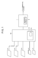
- Fig. 1 is a systematic diagram showing the overall system of a solar power generating device.
- reference numerals 1 to 3 represent standard solar batteries (firsts solar batteries) .
- Each solar standard solar battery has a predetermined number, for example, five solar battery panels connected to one another in series, and can generate rated DC power, that is, standard DC power.
- Reference numerals 4 and 5 represent fractional solar batteries (second solar batteries).
- Each fractional solar battery has solar battery panels whose number is smaller than the predetermined number, for example, three solar battery panels connected to one another in series.
- the DC power generated by each fractional solar battery is smaller than the standard DC power and the voltage of the DC power concerned is smaller than the voltage of the standard DC power.
- Reference numeral 6 represents a connection device containing a boosting circuit (DC/DC converter) described later which is accommodated in a housing 6A.
- Reference numeral 7 represents a power conditioner having an inverter circuit 8 connected to the connection device 6, and the power conditioner 7 is connected to a commercial power system.
- the power conditioner 7 carries out MPPT control (Maximum Power Point Tracking control) of varying the operating point of the solar battery so that the operating point of the solar battery tracks the maximum power point at all times in order to take out the maximum power from the solar battery.
- MPPT control Maximum Power Point Tracking control
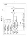
- connection device 6 will be described hereunder in detail with reference to Fig. 2.
- Reference numerals 10A, 10B and 10C represent standard input circuits connected to the standard solar batteries 1, 2 and 3 through terminals 11A, 11B and 11C respectively, and the number of the standard input circuits is equal to the number of the solar batteries to be connected.
- Reference numerals 12A, 12B and 12C represent backflow preventing diodes connected to the output sides of the standard input circuits 10A, 10B and 10C respectively.
- Reference numerals 16A and 16B represent boosting circuits (DC/DC converter), and the boosting circuits 16A and 16B are connected to the fractional solar batteries 4 and 5 through terminals 17A and 17B and first and second voltage sensors 18A and 18B.
- Reference numeral 22 represents a third voltage sensor for detecting the output voltages of the boosting circuits 16A and 16B
- reference numeral 23 represents a fourth voltage sensor for detecting the output voltages of the standard input circuits 10A, 10B and 10C (hereinafter referred to as "standard input voltages").
- control power for the boosting circuits 16A and 16B is achieved from the fractional solar batteries 4 and 5, and thus it does not serve as a load on the solar batteries 1, 2 and 3.
- Reference numeral 24 represents a controller such as a microcomputer or the like.
- the controller 24 is equipped with CPU (central processing unit), RAM (random access memory), ROM (read only memory), which are not shown in the figures, and a timer 25.
- the controller 24 is further equipped with an input voltage detector 26 and an output voltage detector 27. Furthermore, the controller 24 outputs a control signal to the boosting circuits 16A and 16B through a PWM (pulse width modulation) control circuit (pulse width modulation control circuit) 28.
- the connection device 6 is connected to the power conditioner 7 through an output side terminal 30.
- the controller 24 sets the maximum value Vmax of the standard input voltage to zero (reset to zero) (S1), and read in the present standard input voltage Vs detected by the fourth voltage sensor 23 (S2). Subsequently, the controller 24 judges whether the boosting circuits 16A and 16B are stopped (S3) . If they are stopped, the controller 24 reads in the standard input voltage maximum value Vmax which is stored in RAM in advance, and compares the present standard input voltage Vs with the standard input voltage maximum value Vmax (S4).
- the controller 24 judges whether the present standard input voltage Vs is lower than the value achieved by subtracting a preset boosting circuit start judgment voltage Vn stored in RAM from the standard input voltage maximum value Vmax (S5) . If the present standard input voltage V is lower than the value concerned (hereinafter referred to as "lower state"), the timer 25 starts the time counting.
- the inverter circuit 8 As described above, on the basis of the standard input voltage Vs, the standard input voltage maximum value Vmax and the boosting circuit start judging voltage Vn, it is judged through the time counting of the timer 25 that the inverter circuit 8 operates continuously, and then each of the boosting circuits 16A and 16B is controlled to start its operation. Therefore, the inverter circuit 8 provided to the power conditioner 7 is not required to be designed so as to be adaptable to communications. Therefore, the general versatility can be kept, and it is unnecessary to newly provide a current sensor, etc. at the standard input circuit 10A, 10B, 10C side. Accordingly, the rise-up of the cost can be avoided, and when the operation of the boosting circuits 16A, 16B is started, it can be avoided from adversely affecting the MPPT control of the inverter circuit 8.
- the present standard input voltage Vs is kept to the standard input voltage maximum value Vmax (S8) if the controller 24 judges that the present standard input voltage Vs is larger than the standard input voltage maximum value Vmax.
- the time counting of the timer 25 is set to zero (reset to zero) (S9) and the operation of the boosting circuit 16A, 16B is stopped (S10) as in the case where the present standard input voltage Vs is not more than the standard input voltage maximum value Vmax, and as a result of the judgment as to whether the present standard input voltage Vs is lower than the value achieved by subtracting the preset boosting circuit start judging voltage Vn stored in RAM from the standard input voltage maximum value Vmax, the present standard input voltage Vs is not lower than the value concerned.
- the resetting of the timer 25 is not necessarily required to stop the boosting circuits 16A, 16B, and the timer 25 may be reset with some time lag after the boosting circuits 16A, 16B are stopped to check the judgment as to whether the lower state of Vs is continued for a time longer than Tn.
- the timer 25 is reset at the same time when the operation of the boosting circuits 16A, 16B is stopped.
- the stop state of the boosting circuits 16A, 16B is kept from the start time of the time counting until the time-out of the timer when the present standard input voltage Vs is not more than the standard input voltage maximum value Vmax and it is judged whether the present standard input voltage Vs is lower than the value achieved by subtracting the preset boosting circuit start judging voltage Vn stored in RAM from the standard input voltage maximum value Vmax.
- the input voltage detector 26 and the voltage detector 27 of the controller 24 are operated, and the controller 24 controls the boosting circuits 16A and 16B through the PWM control circuit 28 so that the output voltage of the boosting circuits 16A, 16B is kept to be equal to the output voltage of the standard input circuits 10A, 10B and 10C, so that power having a predetermined voltage can be supplied from the solar power generating device.
- the number of the first solar batteries, the number of the second solar batteries, the number of the boosting circuits, and the numbers of the other parts are not limited to those of the above-described embodiment, and they may be properly set to any arbitrary numbers as occasion demands.
Landscapes
- Engineering & Computer Science (AREA)
- Life Sciences & Earth Sciences (AREA)
- Health & Medical Sciences (AREA)
- Physics & Mathematics (AREA)
- Animal Behavior & Ethology (AREA)
- Sustainable Energy (AREA)
- Electromagnetism (AREA)
- General Physics & Mathematics (AREA)
- Radar, Positioning & Navigation (AREA)
- Automation & Control Theory (AREA)
- Sustainable Development (AREA)
- Pharmacology & Pharmacy (AREA)
- Power Engineering (AREA)
- General Health & Medical Sciences (AREA)
- Public Health (AREA)
- Veterinary Medicine (AREA)
- Control Of Electrical Variables (AREA)
- Inverter Devices (AREA)
- Photovoltaic Devices (AREA)
- Physical Or Chemical Processes And Apparatus (AREA)
- Radiation-Therapy Devices (AREA)
Abstract
Description
- The present invention relates to a solar power generating device for supplying power generated by a solar battery, and more particularly to a solar power generating device for boosting DC power generated by a solar battery, converting the thus-boosted solar power to AC power and supplying the AC power thus achieved.
- As this type of solar power generation device has been known a solar power generating device in which DC power generated by a solar battery is boosted by a boosting circuit, the DC power thus boosted is converted to AC power by an inverter circuit, and the AC power thus converted is controlled to be regenerated to a commercial power source system by a controller (for example, see
JP-A-2003-9398 - The solar battery used in the solar power generating device as described above has such a characteristic that the output power of the solar battery increases gradually when the output voltage of the solar battery ranges from Vmax (release voltage) to the maximum power point Pm, and the output power decreases gradually from the maximum power point Pm when the output voltage exceeds the maximum power point Pm and then decreases. Therefore, as the control for taking out the maximum power from the solar battery is known Maximum Power Point Tracking control (hereinafter referred to as "MPPT control") in which the operating point of the solar battery is varied so as to track the maximum power point Pm at all times by an inverter circuit (for example, see
JP-A-11-282553 - However, according to a solar power generating device disclosed in
JP-A-11-282553 - Accordingly, it is required to start the operation of the boosting circuit at the stage that it has been checked that the inverter circuit operates continuously. In this case, the continuous operation of the inverter circuit can be checked by making communications with a control microcomputer of the inverter circuit. Alternatively, the continuous operation of the inverter circuit can be checked by providing voltage and current sensors to the input portion from the standard battery circuit and measuring the power on the basis of the outputs of the voltage and current sensors.
- However, in the former case, it is possible to connect to only an inverter circuit adapted to communications, and it is impossible to connect to an inverter circuit which is not adapted to communications. In the latter case, the number of parts is increased, and the cost rises up.
- Therefore, the present invention has an object to provide a solar power generating device that can keep general versatility, avoid rise-up of the cost and prevent MPPT control of an inverter circuit from being adversely affected when a boosting circuit starts its operation.
- In order to attain the above object, according to a first aspect of the present invention, a solar power generating device including a first solar battery (1, 2, 3) for generating DC power having a prescribed voltage, a second solar battery (4,5)for generating DC power having a voltage lower than the voltage of the first solar battery (1, 2, 3), a boosting circuit (16A, 16B) for boosting the voltage of the DC power generated by the second solar battery (4, 5), and an inverter circuit (8) that converts the DC power boosted by the boosting circuit (16A, 16B) and the DC power generated by the first solar battery to AC power and also carries out MPPT (maximum power point tracking) control, is characterized by comprising: a voltage sensor (23) for detecting the voltage of the DC power generated by the first solar battery; a timer (25) for counting a continuing time for which a state where the detection voltage of the voltage sensor (23) is not more than a predetermined voltage is continued from the time when the first and second solar batteries start power generation; and a controller (24) for starting the operation of the boosting circuit when the count time of the timer is equal to a predetermined time.
- In the solar power generating device, the predetermined voltage is set to a value achieved by subtracting a predetermined voltage from a preset maximum output voltage of the first solar battery.
- In the solar power generating device, when the controller (24) judges that the voltage of the DC power (Vs) generated by the first solar battery (1, 2, 3) is higher than the preset maximum output voltage (Vmax), the controller sets the voltage of the DC power to the preset maximum output voltage, and stops the operation of the boosting circuit (16A, 16B).
- According to the present invention, it is unnecessary to make the inverter circuit adaptable to the communications, the general versatility can be kept and the rise-up of the cost can be avoided. Furthermore, when the boosting circuit starts to operate, it can be prevented from adversely affecting the MPPT control of the inverter circuit.
-
- Fig. 1 is a diagram showing the overall system of a solar power generating device;
- Fig. 2 is a circuit diagram of a connecting device containing a boosting circuit; and
- Fig. 3 is a flowchart showing the control when the boosting circuit starts to operate.
- A preferred embodiment according to the present invention will be described hereunder with reference to the accompanying drawings.
- Fig. 1 is a systematic diagram showing the overall system of a solar power generating device. In Fig. 1,
reference numerals 1 to 3 represent standard solar batteries (firsts solar batteries) . Each solar standard solar battery has a predetermined number, for example, five solar battery panels connected to one another in series, and can generate rated DC power, that is, standard DC power.Reference numerals -
Reference numeral 6 represents a connection device containing a boosting circuit (DC/DC converter) described later which is accommodated in ahousing 6A.Reference numeral 7 represents a power conditioner having aninverter circuit 8 connected to theconnection device 6, and thepower conditioner 7 is connected to a commercial power system. Thepower conditioner 7 carries out MPPT control (Maximum Power Point Tracking control) of varying the operating point of the solar battery so that the operating point of the solar battery tracks the maximum power point at all times in order to take out the maximum power from the solar battery. - The
connection device 6 will be described hereunder in detail with reference to Fig. 2. -
Reference numerals solar batteries terminals Reference numerals standard input circuits -
Reference numerals boosting circuits solar batteries terminals second voltage sensors Reference numeral 22 represents a third voltage sensor for detecting the output voltages of theboosting circuits reference numeral 23 represents a fourth voltage sensor for detecting the output voltages of thestandard input circuits boosting circuits solar batteries solar batteries -
Reference numeral 24 represents a controller such as a microcomputer or the like. Thecontroller 24 is equipped with CPU (central processing unit), RAM (random access memory), ROM (read only memory), which are not shown in the figures, and atimer 25. Thecontroller 24 is further equipped with aninput voltage detector 26 and anoutput voltage detector 27. Furthermore, thecontroller 24 outputs a control signal to theboosting circuits connection device 6 is connected to thepower conditioner 7 through anoutput side terminal 30. - The operation of the solar power generating device, particularly, the operation of the solar power generating device when it starts to operate will be described with reference to the flowchart of Fig. 3.
- First, the
controller 24 sets the maximum value Vmax of the standard input voltage to zero (reset to zero) (S1), and read in the present standard input voltage Vs detected by the fourth voltage sensor 23 (S2). Subsequently, thecontroller 24 judges whether theboosting circuits controller 24 reads in the standard input voltage maximum value Vmax which is stored in RAM in advance, and compares the present standard input voltage Vs with the standard input voltage maximum value Vmax (S4). - If the present standard input voltage Vs is not more than the standard input voltage maximum value Vmax, the
controller 24 judges whether the present standard input voltage Vs is lower than the value achieved by subtracting a preset boosting circuit start judgment voltage Vn stored in RAM from the standard input voltage maximum value Vmax (S5) . If the present standard input voltage V is lower than the value concerned (hereinafter referred to as "lower state"), thetimer 25 starts the time counting. When the lower state concerned is continued for a time longer than a start judging time Tn of theinverter circuit 8 pre-stored in RAM (on the basis of the start judging time Tn, it can be judged that theinverter circuit 8 operates, particularly theinverter circuit 8 operates continuously) and thetimer 25 counts the start judging time Tn and then times out (S6), thecontroller 24 judges that theinverter circuit 8 of thepower conditioner 7 operates. Therefore, thecontroller 24 outputs a starting signal to theboosting circuits boosting circuits - As described above, on the basis of the standard input voltage Vs, the standard input voltage maximum value Vmax and the boosting circuit start judging voltage Vn, it is judged through the time counting of the
timer 25 that theinverter circuit 8 operates continuously, and then each of theboosting circuits inverter circuit 8 provided to thepower conditioner 7 is not required to be designed so as to be adaptable to communications. Therefore, the general versatility can be kept, and it is unnecessary to newly provide a current sensor, etc. at thestandard input circuit boosting circuits inverter circuit 8. - Furthermore, when the standard input voltage maximum value Vmax is read in and compared with the present standard input voltage Vs, the present standard input voltage Vs is kept to the standard input voltage maximum value Vmax (S8) if the
controller 24 judges that the present standard input voltage Vs is larger than the standard input voltage maximum value Vmax. In this case, the time counting of thetimer 25 is set to zero (reset to zero) (S9) and the operation of theboosting circuit timer 25 is not necessarily required to stop theboosting circuits timer 25 may be reset with some time lag after theboosting circuits timer 25 is reset at the same time when the operation of theboosting circuits - Furthermore, it is preferable that the stop state of the
boosting circuits - After each of the boosting
circuits solar batteries second voltage sensors circuits third voltage sensor 22, theinput voltage detector 26 and thevoltage detector 27 of thecontroller 24 are operated, and thecontroller 24 controls the boostingcircuits PWM control circuit 28 so that the output voltage of the boostingcircuits standard input circuits - The present invention is not limited to the above embodiment, and various alternatives, corrections and modifications may be made on the basis of the foregoing description with out departing from the subject matter of the present invention.
- For example, in the above-described embodiment, the number of the first solar batteries, the number of the second solar batteries, the number of the boosting circuits, and the numbers of the other parts are not limited to those of the above-described embodiment, and they may be properly set to any arbitrary numbers as occasion demands.
Claims (4)
- A solar power generating device including a first solar battery (1,2,3) for generating DC power having a prescribed voltage, a second solar battery (4,5)for generating DC power having a voltage lower than the voltage of the first solar battery (1,2,3), a boosting circuit (16A,16B)for boosting the voltage of the DC power generated by the second solar battery (4,5), and an inverter circuit (8) that converts the DC power boosted by the boosting circuit (16A,16B) and the DC power generated by the first solar battery to AC power and also carries out MPPT (maximum power point tracking) control, characterized by comprising:a voltage sensor (23) for detecting the voltage of the DC power generated by the first solar battery;a timer (25) for counting a continuing time for which a state where the detection voltage of the voltage sensor (23) is not more than a predetermined voltage is continued from the time when the first and second solar batteries start power generation; anda controller (24) for starting the operation of the boosting circuit when the count time of the timer is equal to a predetermined time.
- The solar power generating device according to claim 1, wherein the predetermined voltage is set to a value achieved by subtracting a predetermined voltage from a preset maximum output voltage of the first solar battery.
- The solar power generating device according to claim 3, wherein when the controller (24) judges that the voltage of the DC power (Vs) generated by the first solar battery (1, 2, 3) is higher than the preset maximum output voltage (Vmax), the controller sets the voltage of the DC power to the preset maximum output voltage, and stops the operation of the boosting circuit (16A, 16B).
- The solar power generating device according to claim 3, wherein when the controller (24)judges that the voltage of the DC power (Vs) generated by the first solar battery (1, 2, 3) is higher than the preset maximum output voltage (Vmax), the timer (25) resets the counting time to zero.
Applications Claiming Priority (1)
| Application Number | Priority Date | Filing Date | Title |
|---|---|---|---|
| JP2005097643A JP4794189B2 (en) | 2005-03-30 | 2005-03-30 | Solar power plant |
Publications (2)
| Publication Number | Publication Date |
|---|---|
| EP1708070A1 true EP1708070A1 (en) | 2006-10-04 |
| EP1708070B1 EP1708070B1 (en) | 2008-05-07 |
Family
ID=36128606
Family Applications (1)
| Application Number | Title | Priority Date | Filing Date |
|---|---|---|---|
| EP06005204A Expired - Lifetime EP1708070B1 (en) | 2005-03-30 | 2006-03-14 | Solar power generating device |
Country Status (8)
| Country | Link |
|---|---|
| EP (1) | EP1708070B1 (en) |
| JP (1) | JP4794189B2 (en) |
| KR (1) | KR100993652B1 (en) |
| CN (1) | CN100517159C (en) |
| AT (1) | ATE394727T1 (en) |
| DE (1) | DE602006001067D1 (en) |
| ES (1) | ES2306310T3 (en) |
| TW (1) | TWI400594B (en) |
Cited By (54)
| Publication number | Priority date | Publication date | Assignee | Title |
|---|---|---|---|---|
| CN102749931A (en) * | 2012-06-21 | 2012-10-24 | 上海市电力公司 | Photovoltaic energy storage control system |
| US9112379B2 (en) | 2006-12-06 | 2015-08-18 | Solaredge Technologies Ltd. | Pairing of components in a direct current distributed power generation system |
| US9130401B2 (en) | 2006-12-06 | 2015-09-08 | Solaredge Technologies Ltd. | Distributed power harvesting systems using DC power sources |
| US9235228B2 (en) | 2012-03-05 | 2016-01-12 | Solaredge Technologies Ltd. | Direct current link circuit |
| US9291696B2 (en) | 2007-12-05 | 2016-03-22 | Solaredge Technologies Ltd. | Photovoltaic system power tracking method |
| US9318974B2 (en) | 2014-03-26 | 2016-04-19 | Solaredge Technologies Ltd. | Multi-level inverter with flying capacitor topology |
| US9362743B2 (en) | 2008-05-05 | 2016-06-07 | Solaredge Technologies Ltd. | Direct current power combiner |
| US9368964B2 (en) | 2006-12-06 | 2016-06-14 | Solaredge Technologies Ltd. | Distributed power system using direct current power sources |
| US9401599B2 (en) | 2010-12-09 | 2016-07-26 | Solaredge Technologies Ltd. | Disconnection of a string carrying direct current power |
| US9407161B2 (en) | 2007-12-05 | 2016-08-02 | Solaredge Technologies Ltd. | Parallel connected inverters |
| US9537445B2 (en) | 2008-12-04 | 2017-01-03 | Solaredge Technologies Ltd. | Testing of a photovoltaic panel |
| US9543889B2 (en) | 2006-12-06 | 2017-01-10 | Solaredge Technologies Ltd. | Distributed power harvesting systems using DC power sources |
| US9548619B2 (en) | 2013-03-14 | 2017-01-17 | Solaredge Technologies Ltd. | Method and apparatus for storing and depleting energy |
| US9590526B2 (en) | 2006-12-06 | 2017-03-07 | Solaredge Technologies Ltd. | Safety mechanisms, wake up and shutdown methods in distributed power installations |
| US9644993B2 (en) | 2006-12-06 | 2017-05-09 | Solaredge Technologies Ltd. | Monitoring of distributed power harvesting systems using DC power sources |
| US9647442B2 (en) | 2010-11-09 | 2017-05-09 | Solaredge Technologies Ltd. | Arc detection and prevention in a power generation system |
| US9673711B2 (en) | 2007-08-06 | 2017-06-06 | Solaredge Technologies Ltd. | Digital average input current control in power converter |
| US9680304B2 (en) | 2006-12-06 | 2017-06-13 | Solaredge Technologies Ltd. | Method for distributed power harvesting using DC power sources |
| US9812984B2 (en) | 2012-01-30 | 2017-11-07 | Solaredge Technologies Ltd. | Maximizing power in a photovoltaic distributed power system |
| US9819178B2 (en) | 2013-03-15 | 2017-11-14 | Solaredge Technologies Ltd. | Bypass mechanism |
| US9831824B2 (en) | 2007-12-05 | 2017-11-28 | SolareEdge Technologies Ltd. | Current sensing on a MOSFET |
| US9853538B2 (en) | 2007-12-04 | 2017-12-26 | Solaredge Technologies Ltd. | Distributed power harvesting systems using DC power sources |
| US9853565B2 (en) | 2012-01-30 | 2017-12-26 | Solaredge Technologies Ltd. | Maximized power in a photovoltaic distributed power system |
| WO2018002586A1 (en) * | 2016-06-29 | 2018-01-04 | Xiongwei Liu | Electrical coupling apparatus for use in a solar photovoltaic power system and methods of operating the same |
| US9866098B2 (en) | 2011-01-12 | 2018-01-09 | Solaredge Technologies Ltd. | Serially connected inverters |
| US9869701B2 (en) | 2009-05-26 | 2018-01-16 | Solaredge Technologies Ltd. | Theft detection and prevention in a power generation system |
| US9876430B2 (en) | 2008-03-24 | 2018-01-23 | Solaredge Technologies Ltd. | Zero voltage switching |
| US9923516B2 (en) | 2012-01-30 | 2018-03-20 | Solaredge Technologies Ltd. | Photovoltaic panel circuitry |
| US9941813B2 (en) | 2013-03-14 | 2018-04-10 | Solaredge Technologies Ltd. | High frequency multi-level inverter |
| US9960667B2 (en) | 2006-12-06 | 2018-05-01 | Solaredge Technologies Ltd. | System and method for protection during inverter shutdown in distributed power installations |
| US9966766B2 (en) | 2006-12-06 | 2018-05-08 | Solaredge Technologies Ltd. | Battery power delivery module |
| US10115841B2 (en) | 2012-06-04 | 2018-10-30 | Solaredge Technologies Ltd. | Integrated photovoltaic panel circuitry |
| US10230310B2 (en) | 2016-04-05 | 2019-03-12 | Solaredge Technologies Ltd | Safety switch for photovoltaic systems |
| US10396662B2 (en) | 2011-09-12 | 2019-08-27 | Solaredge Technologies Ltd | Direct current link circuit |
| US10673229B2 (en) | 2010-11-09 | 2020-06-02 | Solaredge Technologies Ltd. | Arc detection and prevention in a power generation system |
| US10673222B2 (en) | 2010-11-09 | 2020-06-02 | Solaredge Technologies Ltd. | Arc detection and prevention in a power generation system |
| US10931119B2 (en) | 2012-01-11 | 2021-02-23 | Solaredge Technologies Ltd. | Photovoltaic module |
| US11018623B2 (en) | 2016-04-05 | 2021-05-25 | Solaredge Technologies Ltd. | Safety switch for photovoltaic systems |
| US11177663B2 (en) | 2016-04-05 | 2021-11-16 | Solaredge Technologies Ltd. | Chain of power devices |
| US11264947B2 (en) | 2007-12-05 | 2022-03-01 | Solaredge Technologies Ltd. | Testing of a photovoltaic panel |
| US11296650B2 (en) | 2006-12-06 | 2022-04-05 | Solaredge Technologies Ltd. | System and method for protection during inverter shutdown in distributed power installations |
| US11309832B2 (en) | 2006-12-06 | 2022-04-19 | Solaredge Technologies Ltd. | Distributed power harvesting systems using DC power sources |
| US11569659B2 (en) | 2006-12-06 | 2023-01-31 | Solaredge Technologies Ltd. | Distributed power harvesting systems using DC power sources |
| US11569660B2 (en) | 2006-12-06 | 2023-01-31 | Solaredge Technologies Ltd. | Distributed power harvesting systems using DC power sources |
| US11687112B2 (en) | 2006-12-06 | 2023-06-27 | Solaredge Technologies Ltd. | Distributed power harvesting systems using DC power sources |
| US11728768B2 (en) | 2006-12-06 | 2023-08-15 | Solaredge Technologies Ltd. | Pairing of components in a direct current distributed power generation system |
| US11735910B2 (en) | 2006-12-06 | 2023-08-22 | Solaredge Technologies Ltd. | Distributed power system using direct current power sources |
| US11855231B2 (en) | 2006-12-06 | 2023-12-26 | Solaredge Technologies Ltd. | Distributed power harvesting systems using DC power sources |
| US11881814B2 (en) | 2005-12-05 | 2024-01-23 | Solaredge Technologies Ltd. | Testing of a photovoltaic panel |
| US11888387B2 (en) | 2006-12-06 | 2024-01-30 | Solaredge Technologies Ltd. | Safety mechanisms, wake up and shutdown methods in distributed power installations |
| US12057807B2 (en) | 2016-04-05 | 2024-08-06 | Solaredge Technologies Ltd. | Chain of power devices |
| US12418177B2 (en) | 2009-10-24 | 2025-09-16 | Solaredge Technologies Ltd. | Distributed power system using direct current power sources |
| US12665546B2 (en) | 2011-01-28 | 2026-06-23 | Solaredge Technologies Ltd. | Pairing of components in a direct current distributed power generation system |
| US12676488B2 (en) | 2006-12-06 | 2026-07-07 | Solaredge Technologies Ltd. | System and method for protection during inverter shutdown in distributed power installations |
Families Citing this family (9)
| Publication number | Priority date | Publication date | Assignee | Title |
|---|---|---|---|---|
| JP5354892B2 (en) * | 2007-11-26 | 2013-11-27 | ニッコー株式会社 | Wind power generator |
| US20130241298A1 (en) * | 2010-05-12 | 2013-09-19 | Omron Corporation | Voltage converter, voltage converting method, power adjuster, power adjusting method, photovoltaic system, and management device |
| JP5540893B2 (en) * | 2010-05-31 | 2014-07-02 | 三洋電機株式会社 | Photovoltaic power generation device and connection device |
| JP5659240B2 (en) * | 2010-11-08 | 2015-01-28 | 株式会社日立製作所 | Solar power system |
| CN102200793A (en) * | 2011-05-23 | 2011-09-28 | 昆明理工大学 | Maximum power point detection tracking method and circuit of power generating device |
| WO2013121540A1 (en) * | 2012-02-15 | 2013-08-22 | 東芝三菱電機産業システム株式会社 | Power supply device for power conversion device |
| EP2859650B1 (en) | 2012-05-25 | 2017-02-15 | Solaredge Technologies Ltd. | Circuit for interconnected direct current power sources |
| CN105186563B (en) * | 2015-09-16 | 2018-08-14 | 上海载物能源科技有限公司 | A kind of high-effect solar energy power generating control system and method based on synchronous boost |
| JP7073647B2 (en) * | 2017-08-07 | 2022-05-24 | オムロン株式会社 | Power generation system |
Citations (4)
| Publication number | Priority date | Publication date | Assignee | Title |
|---|---|---|---|---|
| US5327071A (en) * | 1991-11-05 | 1994-07-05 | The United States Of America As Represented By The Administrator Of The National Aeronautics & Space Administration | Microprocessor control of multiple peak power tracking DC/DC converters for use with solar cell arrays |
| EP0947905A2 (en) * | 1998-03-30 | 1999-10-06 | Sanyo Electric Co. Ltd | Solar power generating device |
| JPH11282553A (en) | 1998-03-30 | 1999-10-15 | Sanyo Electric Co Ltd | Solar power generator |
| JP2003009398A (en) | 2001-06-19 | 2003-01-10 | Sanyo Electric Co Ltd | Control method of grid-connected power generator and grid-connected power generator |
Family Cites Families (11)
| Publication number | Priority date | Publication date | Assignee | Title |
|---|---|---|---|---|
| JP3554116B2 (en) * | 1996-09-06 | 2004-08-18 | キヤノン株式会社 | Power control device and solar power generation system using the same |
| JPH10341541A (en) | 1997-06-05 | 1998-12-22 | Toshiba Corp | Battery discharge termination control device |
| JP2001128365A (en) * | 1999-10-25 | 2001-05-11 | Hitachi Ltd | Operating method of solar power generation system |
| JP3747313B2 (en) * | 2000-04-27 | 2006-02-22 | シャープ株式会社 | Grid-connected inverter device |
| JP2002271991A (en) * | 2001-03-14 | 2002-09-20 | Kyocera Corp | Photovoltaic power generation system, method of starting photovoltaic power generation system, and computer-readable recording medium |
| JP3772096B2 (en) * | 2001-04-13 | 2006-05-10 | シャープ株式会社 | Power conditioner for photovoltaic system |
| CN1337775A (en) * | 2001-06-29 | 2002-02-27 | 黎进华 | Solar power generator and its inversion step-up circuit |
| KR100452967B1 (en) | 2002-04-24 | 2004-10-14 | 헥스파워시스템(주) | Apparatus and method for controlling power controller for solar power generation |
| JP2004146791A (en) * | 2002-07-31 | 2004-05-20 | Kyocera Corp | Solar power generator |
| TWI232361B (en) * | 2003-11-25 | 2005-05-11 | Delta Electronics Inc | Maximum-power tracking method and device of solar power generation system |
| TWM258488U (en) * | 2004-02-23 | 2005-03-01 | Hu-Tai Fan | Solar power control apparatus for handheld devices |
-
2005
- 2005-03-30 JP JP2005097643A patent/JP4794189B2/en not_active Expired - Fee Related
-
2006
- 2006-02-16 KR KR1020060014875A patent/KR100993652B1/en not_active Expired - Fee Related
- 2006-03-07 CN CNB2006100568392A patent/CN100517159C/en not_active Expired - Fee Related
- 2006-03-13 TW TW095108349A patent/TWI400594B/en not_active IP Right Cessation
- 2006-03-14 ES ES06005204T patent/ES2306310T3/en not_active Expired - Lifetime
- 2006-03-14 AT AT06005204T patent/ATE394727T1/en not_active IP Right Cessation
- 2006-03-14 DE DE602006001067T patent/DE602006001067D1/en not_active Expired - Lifetime
- 2006-03-14 EP EP06005204A patent/EP1708070B1/en not_active Expired - Lifetime
Patent Citations (4)
| Publication number | Priority date | Publication date | Assignee | Title |
|---|---|---|---|---|
| US5327071A (en) * | 1991-11-05 | 1994-07-05 | The United States Of America As Represented By The Administrator Of The National Aeronautics & Space Administration | Microprocessor control of multiple peak power tracking DC/DC converters for use with solar cell arrays |
| EP0947905A2 (en) * | 1998-03-30 | 1999-10-06 | Sanyo Electric Co. Ltd | Solar power generating device |
| JPH11282553A (en) | 1998-03-30 | 1999-10-15 | Sanyo Electric Co Ltd | Solar power generator |
| JP2003009398A (en) | 2001-06-19 | 2003-01-10 | Sanyo Electric Co Ltd | Control method of grid-connected power generator and grid-connected power generator |
Non-Patent Citations (1)
| Title |
|---|
| WENKAI WU ET AL: "DSP-based multiple peak power tracking for expandable power system", APEC 2003. 18TH. ANNUAL IEEE APPLIED POWER ELECTRONICS CONFERENCE AND EXPOSITION. MIAMI BEACH, FL, FEB. 9 - 13, 2003, ANNUAL APPLIED POWER ELECTRONICS CONFERENCE, NEW YORK, NY : IEEE, US, vol. VOL. 1 OF 2. CONF. 18, 9 February 2003 (2003-02-09), pages 525 - 530, XP010631559, ISBN: 0-7803-7768-0 * |
Cited By (157)
| Publication number | Priority date | Publication date | Assignee | Title |
|---|---|---|---|---|
| US11881814B2 (en) | 2005-12-05 | 2024-01-23 | Solaredge Technologies Ltd. | Testing of a photovoltaic panel |
| US11687112B2 (en) | 2006-12-06 | 2023-06-27 | Solaredge Technologies Ltd. | Distributed power harvesting systems using DC power sources |
| US11658482B2 (en) | 2006-12-06 | 2023-05-23 | Solaredge Technologies Ltd. | Distributed power harvesting systems using DC power sources |
| US12676488B2 (en) | 2006-12-06 | 2026-07-07 | Solaredge Technologies Ltd. | System and method for protection during inverter shutdown in distributed power installations |
| US12388492B2 (en) | 2006-12-06 | 2025-08-12 | Solaredge Technologies Ltd. | Safety mechanisms, wake up and shutdown methods in distributed power installations |
| US12316274B2 (en) | 2006-12-06 | 2025-05-27 | Solaredge Technologies Ltd. | Pairing of components in a direct current distributed power generation system |
| US12281919B2 (en) | 2006-12-06 | 2025-04-22 | Solaredge Technologies Ltd. | Monitoring of distributed power harvesting systems using DC power sources |
| US9368964B2 (en) | 2006-12-06 | 2016-06-14 | Solaredge Technologies Ltd. | Distributed power system using direct current power sources |
| US12276997B2 (en) | 2006-12-06 | 2025-04-15 | Solaredge Technologies Ltd. | Distributed power harvesting systems using DC power sources |
| US12224706B2 (en) | 2006-12-06 | 2025-02-11 | Solaredge Technologies Ltd. | Pairing of components in a direct current distributed power generation system |
| US12107417B2 (en) | 2006-12-06 | 2024-10-01 | Solaredge Technologies Ltd. | Distributed power harvesting systems using DC power sources |
| US9543889B2 (en) | 2006-12-06 | 2017-01-10 | Solaredge Technologies Ltd. | Distributed power harvesting systems using DC power sources |
| US12068599B2 (en) | 2006-12-06 | 2024-08-20 | Solaredge Technologies Ltd. | System and method for protection during inverter shutdown in distributed power installations |
| US9590526B2 (en) | 2006-12-06 | 2017-03-07 | Solaredge Technologies Ltd. | Safety mechanisms, wake up and shutdown methods in distributed power installations |
| US12046940B2 (en) | 2006-12-06 | 2024-07-23 | Solaredge Technologies Ltd. | Battery power control |
| US9644993B2 (en) | 2006-12-06 | 2017-05-09 | Solaredge Technologies Ltd. | Monitoring of distributed power harvesting systems using DC power sources |
| US12032080B2 (en) | 2006-12-06 | 2024-07-09 | Solaredge Technologies Ltd. | Safety mechanisms, wake up and shutdown methods in distributed power installations |
| US11031861B2 (en) | 2006-12-06 | 2021-06-08 | Solaredge Technologies Ltd. | System and method for protection during inverter shutdown in distributed power installations |
| US9680304B2 (en) | 2006-12-06 | 2017-06-13 | Solaredge Technologies Ltd. | Method for distributed power harvesting using DC power sources |
| US12027849B2 (en) | 2006-12-06 | 2024-07-02 | Solaredge Technologies Ltd. | Distributed power system using direct current power sources |
| US12027970B2 (en) | 2006-12-06 | 2024-07-02 | Solaredge Technologies Ltd. | Safety mechanisms, wake up and shutdown methods in distributed power installations |
| US11962243B2 (en) | 2006-12-06 | 2024-04-16 | Solaredge Technologies Ltd. | Method for distributed power harvesting using DC power sources |
| US11043820B2 (en) | 2006-12-06 | 2021-06-22 | Solaredge Technologies Ltd. | Battery power delivery module |
| US11961922B2 (en) | 2006-12-06 | 2024-04-16 | Solaredge Technologies Ltd. | Distributed power harvesting systems using DC power sources |
| US9853490B2 (en) | 2006-12-06 | 2017-12-26 | Solaredge Technologies Ltd. | Distributed power system using direct current power sources |
| US11888387B2 (en) | 2006-12-06 | 2024-01-30 | Solaredge Technologies Ltd. | Safety mechanisms, wake up and shutdown methods in distributed power installations |
| US9112379B2 (en) | 2006-12-06 | 2015-08-18 | Solaredge Technologies Ltd. | Pairing of components in a direct current distributed power generation system |
| US11855231B2 (en) | 2006-12-06 | 2023-12-26 | Solaredge Technologies Ltd. | Distributed power harvesting systems using DC power sources |
| US11735910B2 (en) | 2006-12-06 | 2023-08-22 | Solaredge Technologies Ltd. | Distributed power system using direct current power sources |
| US11728768B2 (en) | 2006-12-06 | 2023-08-15 | Solaredge Technologies Ltd. | Pairing of components in a direct current distributed power generation system |
| US9960731B2 (en) | 2006-12-06 | 2018-05-01 | Solaredge Technologies Ltd. | Pairing of components in a direct current distributed power generation system |
| US9130401B2 (en) | 2006-12-06 | 2015-09-08 | Solaredge Technologies Ltd. | Distributed power harvesting systems using DC power sources |
| US11682918B2 (en) | 2006-12-06 | 2023-06-20 | Solaredge Technologies Ltd. | Battery power delivery module |
| US11002774B2 (en) | 2006-12-06 | 2021-05-11 | Solaredge Technologies Ltd. | Monitoring of distributed power harvesting systems using DC power sources |
| US9960667B2 (en) | 2006-12-06 | 2018-05-01 | Solaredge Technologies Ltd. | System and method for protection during inverter shutdown in distributed power installations |
| US9966766B2 (en) | 2006-12-06 | 2018-05-08 | Solaredge Technologies Ltd. | Battery power delivery module |
| US9948233B2 (en) | 2006-12-06 | 2018-04-17 | Solaredge Technologies Ltd. | Distributed power harvesting systems using DC power sources |
| US11598652B2 (en) | 2006-12-06 | 2023-03-07 | Solaredge Technologies Ltd. | Monitoring of distributed power harvesting systems using DC power sources |
| US10097007B2 (en) | 2006-12-06 | 2018-10-09 | Solaredge Technologies Ltd. | Method for distributed power harvesting using DC power sources |
| US11063440B2 (en) | 2006-12-06 | 2021-07-13 | Solaredge Technologies Ltd. | Method for distributed power harvesting using DC power sources |
| US11594882B2 (en) | 2006-12-06 | 2023-02-28 | Solaredge Technologies Ltd. | Distributed power harvesting systems using DC power sources |
| US11594880B2 (en) | 2006-12-06 | 2023-02-28 | Solaredge Technologies Ltd. | Distributed power harvesting systems using DC power sources |
| US10230245B2 (en) | 2006-12-06 | 2019-03-12 | Solaredge Technologies Ltd | Battery power delivery module |
| US11594881B2 (en) | 2006-12-06 | 2023-02-28 | Solaredge Technologies Ltd. | Distributed power harvesting systems using DC power sources |
| US11073543B2 (en) | 2006-12-06 | 2021-07-27 | Solaredge Technologies Ltd. | Monitoring of distributed power harvesting systems using DC power sources |
| US10447150B2 (en) | 2006-12-06 | 2019-10-15 | Solaredge Technologies Ltd. | Distributed power harvesting systems using DC power sources |
| US11579235B2 (en) | 2006-12-06 | 2023-02-14 | Solaredge Technologies Ltd. | Safety mechanisms, wake up and shutdown methods in distributed power installations |
| US11575260B2 (en) | 2006-12-06 | 2023-02-07 | Solaredge Technologies Ltd. | Distributed power harvesting systems using DC power sources |
| US11183922B2 (en) | 2006-12-06 | 2021-11-23 | Solaredge Technologies Ltd. | Distributed power harvesting systems using DC power sources |
| US11575261B2 (en) | 2006-12-06 | 2023-02-07 | Solaredge Technologies Ltd. | Distributed power harvesting systems using DC power sources |
| US10637393B2 (en) | 2006-12-06 | 2020-04-28 | Solaredge Technologies Ltd. | Distributed power harvesting systems using DC power sources |
| US11569660B2 (en) | 2006-12-06 | 2023-01-31 | Solaredge Technologies Ltd. | Distributed power harvesting systems using DC power sources |
| US11569659B2 (en) | 2006-12-06 | 2023-01-31 | Solaredge Technologies Ltd. | Distributed power harvesting systems using DC power sources |
| US11476799B2 (en) | 2006-12-06 | 2022-10-18 | Solaredge Technologies Ltd. | Distributed power harvesting systems using DC power sources |
| US11309832B2 (en) | 2006-12-06 | 2022-04-19 | Solaredge Technologies Ltd. | Distributed power harvesting systems using DC power sources |
| US11296650B2 (en) | 2006-12-06 | 2022-04-05 | Solaredge Technologies Ltd. | System and method for protection during inverter shutdown in distributed power installations |
| US10673253B2 (en) | 2006-12-06 | 2020-06-02 | Solaredge Technologies Ltd. | Battery power delivery module |
| US10516336B2 (en) | 2007-08-06 | 2019-12-24 | Solaredge Technologies Ltd. | Digital average input current control in power converter |
| US11594968B2 (en) | 2007-08-06 | 2023-02-28 | Solaredge Technologies Ltd. | Digital average input current control in power converter |
| US10116217B2 (en) | 2007-08-06 | 2018-10-30 | Solaredge Technologies Ltd. | Digital average input current control in power converter |
| US9673711B2 (en) | 2007-08-06 | 2017-06-06 | Solaredge Technologies Ltd. | Digital average input current control in power converter |
| US9853538B2 (en) | 2007-12-04 | 2017-12-26 | Solaredge Technologies Ltd. | Distributed power harvesting systems using DC power sources |
| US11894806B2 (en) | 2007-12-05 | 2024-02-06 | Solaredge Technologies Ltd. | Testing of a photovoltaic panel |
| US11183969B2 (en) | 2007-12-05 | 2021-11-23 | Solaredge Technologies Ltd. | Testing of a photovoltaic panel |
| US11693080B2 (en) | 2007-12-05 | 2023-07-04 | Solaredge Technologies Ltd. | Parallel connected inverters |
| US12055647B2 (en) | 2007-12-05 | 2024-08-06 | Solaredge Technologies Ltd. | Parallel connected inverters |
| US9979280B2 (en) | 2007-12-05 | 2018-05-22 | Solaredge Technologies Ltd. | Parallel connected inverters |
| US10644589B2 (en) | 2007-12-05 | 2020-05-05 | Solaredge Technologies Ltd. | Parallel connected inverters |
| US9291696B2 (en) | 2007-12-05 | 2016-03-22 | Solaredge Technologies Ltd. | Photovoltaic system power tracking method |
| US11264947B2 (en) | 2007-12-05 | 2022-03-01 | Solaredge Technologies Ltd. | Testing of a photovoltaic panel |
| US10693415B2 (en) | 2007-12-05 | 2020-06-23 | Solaredge Technologies Ltd. | Testing of a photovoltaic panel |
| US9831824B2 (en) | 2007-12-05 | 2017-11-28 | SolareEdge Technologies Ltd. | Current sensing on a MOSFET |
| US9407161B2 (en) | 2007-12-05 | 2016-08-02 | Solaredge Technologies Ltd. | Parallel connected inverters |
| US11183923B2 (en) | 2007-12-05 | 2021-11-23 | Solaredge Technologies Ltd. | Parallel connected inverters |
| US9876430B2 (en) | 2008-03-24 | 2018-01-23 | Solaredge Technologies Ltd. | Zero voltage switching |
| US9362743B2 (en) | 2008-05-05 | 2016-06-07 | Solaredge Technologies Ltd. | Direct current power combiner |
| US11424616B2 (en) | 2008-05-05 | 2022-08-23 | Solaredge Technologies Ltd. | Direct current power combiner |
| US12218498B2 (en) | 2008-05-05 | 2025-02-04 | Solaredge Technologies Ltd. | Direct current power combiner |
| US10468878B2 (en) | 2008-05-05 | 2019-11-05 | Solaredge Technologies Ltd. | Direct current power combiner |
| US10461687B2 (en) | 2008-12-04 | 2019-10-29 | Solaredge Technologies Ltd. | Testing of a photovoltaic panel |
| US9537445B2 (en) | 2008-12-04 | 2017-01-03 | Solaredge Technologies Ltd. | Testing of a photovoltaic panel |
| US11867729B2 (en) | 2009-05-26 | 2024-01-09 | Solaredge Technologies Ltd. | Theft detection and prevention in a power generation system |
| US12306215B2 (en) | 2009-05-26 | 2025-05-20 | Solaredge Technologies Ltd. | Theft detection and prevention in a power generation system |
| US9869701B2 (en) | 2009-05-26 | 2018-01-16 | Solaredge Technologies Ltd. | Theft detection and prevention in a power generation system |
| US10969412B2 (en) | 2009-05-26 | 2021-04-06 | Solaredge Technologies Ltd. | Theft detection and prevention in a power generation system |
| US12418177B2 (en) | 2009-10-24 | 2025-09-16 | Solaredge Technologies Ltd. | Distributed power system using direct current power sources |
| US10673229B2 (en) | 2010-11-09 | 2020-06-02 | Solaredge Technologies Ltd. | Arc detection and prevention in a power generation system |
| US11070051B2 (en) | 2010-11-09 | 2021-07-20 | Solaredge Technologies Ltd. | Arc detection and prevention in a power generation system |
| US10931228B2 (en) | 2010-11-09 | 2021-02-23 | Solaredge Technologies Ftd. | Arc detection and prevention in a power generation system |
| US12407158B2 (en) | 2010-11-09 | 2025-09-02 | Solaredge Technologies Ltd. | Arc detection and prevention in a power generation system |
| US11489330B2 (en) | 2010-11-09 | 2022-11-01 | Solaredge Technologies Ltd. | Arc detection and prevention in a power generation system |
| US10673222B2 (en) | 2010-11-09 | 2020-06-02 | Solaredge Technologies Ltd. | Arc detection and prevention in a power generation system |
| US9647442B2 (en) | 2010-11-09 | 2017-05-09 | Solaredge Technologies Ltd. | Arc detection and prevention in a power generation system |
| US11349432B2 (en) | 2010-11-09 | 2022-05-31 | Solaredge Technologies Ltd. | Arc detection and prevention in a power generation system |
| US12003215B2 (en) | 2010-11-09 | 2024-06-04 | Solaredge Technologies Ltd. | Arc detection and prevention in a power generation system |
| US12295184B2 (en) | 2010-12-09 | 2025-05-06 | Solaredge Technologies Ltd. | Disconnection of a string carrying direct current power |
| US9401599B2 (en) | 2010-12-09 | 2016-07-26 | Solaredge Technologies Ltd. | Disconnection of a string carrying direct current power |
| US9935458B2 (en) | 2010-12-09 | 2018-04-03 | Solaredge Technologies Ltd. | Disconnection of a string carrying direct current power |
| US11996488B2 (en) | 2010-12-09 | 2024-05-28 | Solaredge Technologies Ltd. | Disconnection of a string carrying direct current power |
| US11271394B2 (en) | 2010-12-09 | 2022-03-08 | Solaredge Technologies Ltd. | Disconnection of a string carrying direct current power |
| US9866098B2 (en) | 2011-01-12 | 2018-01-09 | Solaredge Technologies Ltd. | Serially connected inverters |
| US11205946B2 (en) | 2011-01-12 | 2021-12-21 | Solaredge Technologies Ltd. | Serially connected inverters |
| US10666125B2 (en) | 2011-01-12 | 2020-05-26 | Solaredge Technologies Ltd. | Serially connected inverters |
| US12218505B2 (en) | 2011-01-12 | 2025-02-04 | Solaredge Technologies Ltd. | Serially connected inverters |
| US12665546B2 (en) | 2011-01-28 | 2026-06-23 | Solaredge Technologies Ltd. | Pairing of components in a direct current distributed power generation system |
| US10396662B2 (en) | 2011-09-12 | 2019-08-27 | Solaredge Technologies Ltd | Direct current link circuit |
| US11979037B2 (en) | 2012-01-11 | 2024-05-07 | Solaredge Technologies Ltd. | Photovoltaic module |
| US10931119B2 (en) | 2012-01-11 | 2021-02-23 | Solaredge Technologies Ltd. | Photovoltaic module |
| US9923516B2 (en) | 2012-01-30 | 2018-03-20 | Solaredge Technologies Ltd. | Photovoltaic panel circuitry |
| US10381977B2 (en) | 2012-01-30 | 2019-08-13 | Solaredge Technologies Ltd | Photovoltaic panel circuitry |
| US12094306B2 (en) | 2012-01-30 | 2024-09-17 | Solaredge Technologies Ltd. | Photovoltaic panel circuitry |
| US11183968B2 (en) | 2012-01-30 | 2021-11-23 | Solaredge Technologies Ltd. | Photovoltaic panel circuitry |
| US10992238B2 (en) | 2012-01-30 | 2021-04-27 | Solaredge Technologies Ltd. | Maximizing power in a photovoltaic distributed power system |
| US11620885B2 (en) | 2012-01-30 | 2023-04-04 | Solaredge Technologies Ltd. | Photovoltaic panel circuitry |
| US12633754B2 (en) | 2012-01-30 | 2026-05-19 | Solaredge Technologies Ltd. | Maximizing power in a photovoltaic distributed power system |
| US12191668B2 (en) | 2012-01-30 | 2025-01-07 | Solaredge Technologies Ltd. | Maximizing power in a photovoltaic distributed power system |
| US9812984B2 (en) | 2012-01-30 | 2017-11-07 | Solaredge Technologies Ltd. | Maximizing power in a photovoltaic distributed power system |
| US10608553B2 (en) | 2012-01-30 | 2020-03-31 | Solaredge Technologies Ltd. | Maximizing power in a photovoltaic distributed power system |
| US11929620B2 (en) | 2012-01-30 | 2024-03-12 | Solaredge Technologies Ltd. | Maximizing power in a photovoltaic distributed power system |
| US9853565B2 (en) | 2012-01-30 | 2017-12-26 | Solaredge Technologies Ltd. | Maximized power in a photovoltaic distributed power system |
| US10007288B2 (en) | 2012-03-05 | 2018-06-26 | Solaredge Technologies Ltd. | Direct current link circuit |
| US9235228B2 (en) | 2012-03-05 | 2016-01-12 | Solaredge Technologies Ltd. | Direct current link circuit |
| US9639106B2 (en) | 2012-03-05 | 2017-05-02 | Solaredge Technologies Ltd. | Direct current link circuit |
| US10115841B2 (en) | 2012-06-04 | 2018-10-30 | Solaredge Technologies Ltd. | Integrated photovoltaic panel circuitry |
| US12218628B2 (en) | 2012-06-04 | 2025-02-04 | Solaredge Technologies Ltd. | Integrated photovoltaic panel circuitry |
| US11177768B2 (en) | 2012-06-04 | 2021-11-16 | Solaredge Technologies Ltd. | Integrated photovoltaic panel circuitry |
| CN102749931A (en) * | 2012-06-21 | 2012-10-24 | 上海市电力公司 | Photovoltaic energy storage control system |
| US10778025B2 (en) | 2013-03-14 | 2020-09-15 | Solaredge Technologies Ltd. | Method and apparatus for storing and depleting energy |
| US12255457B2 (en) | 2013-03-14 | 2025-03-18 | Solaredge Technologies Ltd. | Method and apparatus for storing and depleting energy |
| US12003107B2 (en) | 2013-03-14 | 2024-06-04 | Solaredge Technologies Ltd. | Method and apparatus for storing and depleting energy |
| US11545912B2 (en) | 2013-03-14 | 2023-01-03 | Solaredge Technologies Ltd. | High frequency multi-level inverter |
| US9548619B2 (en) | 2013-03-14 | 2017-01-17 | Solaredge Technologies Ltd. | Method and apparatus for storing and depleting energy |
| US11742777B2 (en) | 2013-03-14 | 2023-08-29 | Solaredge Technologies Ltd. | High frequency multi-level inverter |
| US9941813B2 (en) | 2013-03-14 | 2018-04-10 | Solaredge Technologies Ltd. | High frequency multi-level inverter |
| US12119758B2 (en) | 2013-03-14 | 2024-10-15 | Solaredge Technologies Ltd. | High frequency multi-level inverter |
| US11424617B2 (en) | 2013-03-15 | 2022-08-23 | Solaredge Technologies Ltd. | Bypass mechanism |
| US10651647B2 (en) | 2013-03-15 | 2020-05-12 | Solaredge Technologies Ltd. | Bypass mechanism |
| US12132125B2 (en) | 2013-03-15 | 2024-10-29 | Solaredge Technologies Ltd. | Bypass mechanism |
| US9819178B2 (en) | 2013-03-15 | 2017-11-14 | Solaredge Technologies Ltd. | Bypass mechanism |
| US10886831B2 (en) | 2014-03-26 | 2021-01-05 | Solaredge Technologies Ltd. | Multi-level inverter |
| US9318974B2 (en) | 2014-03-26 | 2016-04-19 | Solaredge Technologies Ltd. | Multi-level inverter with flying capacitor topology |
| US12683516B2 (en) | 2014-03-26 | 2026-07-14 | Solaredge Technologies Ltd. | Multi-level inverter |
| US11296590B2 (en) | 2014-03-26 | 2022-04-05 | Solaredge Technologies Ltd. | Multi-level inverter |
| US11632058B2 (en) | 2014-03-26 | 2023-04-18 | Solaredge Technologies Ltd. | Multi-level inverter |
| US11855552B2 (en) | 2014-03-26 | 2023-12-26 | Solaredge Technologies Ltd. | Multi-level inverter |
| US10886832B2 (en) | 2014-03-26 | 2021-01-05 | Solaredge Technologies Ltd. | Multi-level inverter |
| US12136890B2 (en) | 2014-03-26 | 2024-11-05 | Solaredge Technologies Ltd. | Multi-level inverter |
| US12348182B2 (en) | 2016-04-05 | 2025-07-01 | Solaredge Technologies Ltd. | Safety switch for photovoltaic systems |
| US12057807B2 (en) | 2016-04-05 | 2024-08-06 | Solaredge Technologies Ltd. | Chain of power devices |
| US11018623B2 (en) | 2016-04-05 | 2021-05-25 | Solaredge Technologies Ltd. | Safety switch for photovoltaic systems |
| US12627140B2 (en) | 2016-04-05 | 2026-05-12 | Solaredge Technologies Ltd. | Chain of power devices |
| US11870250B2 (en) | 2016-04-05 | 2024-01-09 | Solaredge Technologies Ltd. | Chain of power devices |
| US11177663B2 (en) | 2016-04-05 | 2021-11-16 | Solaredge Technologies Ltd. | Chain of power devices |
| US10230310B2 (en) | 2016-04-05 | 2019-03-12 | Solaredge Technologies Ltd | Safety switch for photovoltaic systems |
| US11201476B2 (en) | 2016-04-05 | 2021-12-14 | Solaredge Technologies Ltd. | Photovoltaic power device and wiring |
| WO2018002586A1 (en) * | 2016-06-29 | 2018-01-04 | Xiongwei Liu | Electrical coupling apparatus for use in a solar photovoltaic power system and methods of operating the same |
| US11018622B2 (en) | 2016-06-29 | 2021-05-25 | Entrust Smart Home Microgrid Ltd. | Electrical coupling apparatus for use in a solar photovoltaic power system and methods of operating the same |
Also Published As
| Publication number | Publication date |
|---|---|
| TW200643678A (en) | 2006-12-16 |
| TWI400594B (en) | 2013-07-01 |
| ATE394727T1 (en) | 2008-05-15 |
| CN100517159C (en) | 2009-07-22 |
| KR100993652B1 (en) | 2010-11-10 |
| ES2306310T3 (en) | 2008-11-01 |
| EP1708070B1 (en) | 2008-05-07 |
| DE602006001067D1 (en) | 2008-06-19 |
| KR20060106646A (en) | 2006-10-12 |
| JP2006278858A (en) | 2006-10-12 |
| JP4794189B2 (en) | 2011-10-19 |
| CN1841254A (en) | 2006-10-04 |
Similar Documents
| Publication | Publication Date | Title |
|---|---|---|
| EP1708070B1 (en) | Solar power generating device | |
| KR100686281B1 (en) | Method for operating a power supply system having an inverter connected in parallel and a power conversion system | |
| US6838611B2 (en) | Solar battery module and power generation apparatus | |
| JP4719434B2 (en) | Solar cell power generator | |
| JP6566355B2 (en) | Power converter | |
| EP2768132B1 (en) | Power conditioner, photovoltaic system, and abnormality determination method | |
| JP2014075855A (en) | Power control system and photovoltaic power generation system | |
| JP2003289626A (en) | Power conditioner for solar power generation system | |
| JP2005269843A (en) | Grid interconnection device | |
| JP4039097B2 (en) | Solar power system | |
| JPH07325635A (en) | Inverter output controller | |
| JP6537723B2 (en) | Grid-connected inverter device | |
| JP3570283B2 (en) | Battery charging / discharging device | |
| KR20060112680A (en) | Fuel cell system and fuel cell current correction method | |
| US20180175625A1 (en) | Control of a multiple input solar power inverter | |
| JP5540893B2 (en) | Photovoltaic power generation device and connection device | |
| JP2007244195A (en) | Power-saving device and its operation method | |
| JP3451945B2 (en) | Solar power inverter | |
| JP2006310400A (en) | Solar cell control device and ventilation system using the same | |
| JP2000236623A (en) | Overvoltage detection device | |
| JPH0534199Y2 (en) | ||
| JP2752067B2 (en) | Grid-connected inverter device | |
| JP2000245074A (en) | How to prevent storage battery capacity drop | |
| US20250167551A1 (en) | Frequency stabilization system and frequency stabilization method | |
| JP6927836B2 (en) | Power storage system |
Legal Events
| Date | Code | Title | Description |
|---|---|---|---|
| PUAI | Public reference made under article 153(3) epc to a published international application that has entered the european phase |
Free format text: ORIGINAL CODE: 0009012 |
|
| AK | Designated contracting states |
Kind code of ref document: A1 Designated state(s): AT BE BG CH CY CZ DE DK EE ES FI FR GB GR HU IE IS IT LI LT LU LV MC NL PL PT RO SE SI SK TR |
|
| AX | Request for extension of the european patent |
Extension state: AL BA HR MK YU |
|
| 17P | Request for examination filed |
Effective date: 20061108 |
|
| 17Q | First examination report despatched |
Effective date: 20061211 |
|
| AKX | Designation fees paid |
Designated state(s): AT BE BG CH CY CZ DE DK EE ES FI FR GB GR HU IE IS IT LI LT LU LV MC NL PL PT RO SE SI SK TR |
|
| GRAP | Despatch of communication of intention to grant a patent |
Free format text: ORIGINAL CODE: EPIDOSNIGR1 |
|
| GRAS | Grant fee paid |
Free format text: ORIGINAL CODE: EPIDOSNIGR3 |
|
| GRAA | (expected) grant |
Free format text: ORIGINAL CODE: 0009210 |
|
| AK | Designated contracting states |
Kind code of ref document: B1 Designated state(s): AT BE BG CH CY CZ DE DK EE ES FI FR GB GR HU IE IS IT LI LT LU LV MC NL PL PT RO SE SI SK TR |
|
| REG | Reference to a national code |
Ref country code: GB Ref legal event code: FG4D |
|
| REG | Reference to a national code |
Ref country code: CH Ref legal event code: EP |
|
| REG | Reference to a national code |
Ref country code: IE Ref legal event code: FG4D Free format text: LANGUAGE OF EP DOCUMENT: FRENCH |
|
| REF | Corresponds to: |
Ref document number: 602006001067 Country of ref document: DE Date of ref document: 20080619 Kind code of ref document: P |
|
| PG25 | Lapsed in a contracting state [announced via postgrant information from national office to epo] |
Ref country code: SI Free format text: LAPSE BECAUSE OF FAILURE TO SUBMIT A TRANSLATION OF THE DESCRIPTION OR TO PAY THE FEE WITHIN THE PRESCRIBED TIME-LIMIT Effective date: 20080507 |
|
| PG25 | Lapsed in a contracting state [announced via postgrant information from national office to epo] |
Ref country code: FI Free format text: LAPSE BECAUSE OF FAILURE TO SUBMIT A TRANSLATION OF THE DESCRIPTION OR TO PAY THE FEE WITHIN THE PRESCRIBED TIME-LIMIT Effective date: 20080507 Ref country code: NL Free format text: LAPSE BECAUSE OF FAILURE TO SUBMIT A TRANSLATION OF THE DESCRIPTION OR TO PAY THE FEE WITHIN THE PRESCRIBED TIME-LIMIT Effective date: 20080507 |
|
| REG | Reference to a national code |
Ref country code: ES Ref legal event code: FG2A Ref document number: 2306310 Country of ref document: ES Kind code of ref document: T3 |
|
| NLV1 | Nl: lapsed or annulled due to failure to fulfill the requirements of art. 29p and 29m of the patents act | ||
| PG25 | Lapsed in a contracting state [announced via postgrant information from national office to epo] |
Ref country code: LV Free format text: LAPSE BECAUSE OF FAILURE TO SUBMIT A TRANSLATION OF THE DESCRIPTION OR TO PAY THE FEE WITHIN THE PRESCRIBED TIME-LIMIT Effective date: 20080507 Ref country code: AT Free format text: LAPSE BECAUSE OF FAILURE TO SUBMIT A TRANSLATION OF THE DESCRIPTION OR TO PAY THE FEE WITHIN THE PRESCRIBED TIME-LIMIT Effective date: 20080507 Ref country code: PL Free format text: LAPSE BECAUSE OF FAILURE TO SUBMIT A TRANSLATION OF THE DESCRIPTION OR TO PAY THE FEE WITHIN THE PRESCRIBED TIME-LIMIT Effective date: 20080507 |
|
| PG25 | Lapsed in a contracting state [announced via postgrant information from national office to epo] |
Ref country code: IS Free format text: LAPSE BECAUSE OF FAILURE TO SUBMIT A TRANSLATION OF THE DESCRIPTION OR TO PAY THE FEE WITHIN THE PRESCRIBED TIME-LIMIT Effective date: 20080907 |
|
| PG25 | Lapsed in a contracting state [announced via postgrant information from national office to epo] |
Ref country code: LT Free format text: LAPSE BECAUSE OF FAILURE TO SUBMIT A TRANSLATION OF THE DESCRIPTION OR TO PAY THE FEE WITHIN THE PRESCRIBED TIME-LIMIT Effective date: 20080507 Ref country code: CZ Free format text: LAPSE BECAUSE OF FAILURE TO SUBMIT A TRANSLATION OF THE DESCRIPTION OR TO PAY THE FEE WITHIN THE PRESCRIBED TIME-LIMIT Effective date: 20080507 Ref country code: DK Free format text: LAPSE BECAUSE OF FAILURE TO SUBMIT A TRANSLATION OF THE DESCRIPTION OR TO PAY THE FEE WITHIN THE PRESCRIBED TIME-LIMIT Effective date: 20080507 Ref country code: SE Free format text: LAPSE BECAUSE OF FAILURE TO SUBMIT A TRANSLATION OF THE DESCRIPTION OR TO PAY THE FEE WITHIN THE PRESCRIBED TIME-LIMIT Effective date: 20080807 |
|
| PG25 | Lapsed in a contracting state [announced via postgrant information from national office to epo] |
Ref country code: BE Free format text: LAPSE BECAUSE OF FAILURE TO SUBMIT A TRANSLATION OF THE DESCRIPTION OR TO PAY THE FEE WITHIN THE PRESCRIBED TIME-LIMIT Effective date: 20080507 Ref country code: PT Free format text: LAPSE BECAUSE OF FAILURE TO SUBMIT A TRANSLATION OF THE DESCRIPTION OR TO PAY THE FEE WITHIN THE PRESCRIBED TIME-LIMIT Effective date: 20081007 Ref country code: SK Free format text: LAPSE BECAUSE OF FAILURE TO SUBMIT A TRANSLATION OF THE DESCRIPTION OR TO PAY THE FEE WITHIN THE PRESCRIBED TIME-LIMIT Effective date: 20080507 Ref country code: RO Free format text: LAPSE BECAUSE OF FAILURE TO SUBMIT A TRANSLATION OF THE DESCRIPTION OR TO PAY THE FEE WITHIN THE PRESCRIBED TIME-LIMIT Effective date: 20080507 |
|
| PLBE | No opposition filed within time limit |
Free format text: ORIGINAL CODE: 0009261 |
|
| STAA | Information on the status of an ep patent application or granted ep patent |
Free format text: STATUS: NO OPPOSITION FILED WITHIN TIME LIMIT |
|
| 26N | No opposition filed |
Effective date: 20090210 |
|
| PG25 | Lapsed in a contracting state [announced via postgrant information from national office to epo] |
Ref country code: EE Free format text: LAPSE BECAUSE OF FAILURE TO SUBMIT A TRANSLATION OF THE DESCRIPTION OR TO PAY THE FEE WITHIN THE PRESCRIBED TIME-LIMIT Effective date: 20080507 Ref country code: BG Free format text: LAPSE BECAUSE OF FAILURE TO SUBMIT A TRANSLATION OF THE DESCRIPTION OR TO PAY THE FEE WITHIN THE PRESCRIBED TIME-LIMIT Effective date: 20080807 |
|
| PG25 | Lapsed in a contracting state [announced via postgrant information from national office to epo] |
Ref country code: MC Free format text: LAPSE BECAUSE OF NON-PAYMENT OF DUE FEES Effective date: 20090331 |
|
| REG | Reference to a national code |
Ref country code: IE Ref legal event code: MM4A |
|
| PG25 | Lapsed in a contracting state [announced via postgrant information from national office to epo] |
Ref country code: IE Free format text: LAPSE BECAUSE OF NON-PAYMENT OF DUE FEES Effective date: 20090314 |
|
| PG25 | Lapsed in a contracting state [announced via postgrant information from national office to epo] |
Ref country code: GR Free format text: LAPSE BECAUSE OF FAILURE TO SUBMIT A TRANSLATION OF THE DESCRIPTION OR TO PAY THE FEE WITHIN THE PRESCRIBED TIME-LIMIT Effective date: 20080808 |
|
| REG | Reference to a national code |
Ref country code: CH Ref legal event code: PL |
|
| GBPC | Gb: european patent ceased through non-payment of renewal fee |
Effective date: 20100314 |
|
| PG25 | Lapsed in a contracting state [announced via postgrant information from national office to epo] |
Ref country code: CH Free format text: LAPSE BECAUSE OF NON-PAYMENT OF DUE FEES Effective date: 20100331 Ref country code: LI Free format text: LAPSE BECAUSE OF NON-PAYMENT OF DUE FEES Effective date: 20100331 |
|
| PG25 | Lapsed in a contracting state [announced via postgrant information from national office to epo] |
Ref country code: GB Free format text: LAPSE BECAUSE OF NON-PAYMENT OF DUE FEES Effective date: 20100314 |
|
| PG25 | Lapsed in a contracting state [announced via postgrant information from national office to epo] |
Ref country code: LU Free format text: LAPSE BECAUSE OF NON-PAYMENT OF DUE FEES Effective date: 20090314 |
|
| PG25 | Lapsed in a contracting state [announced via postgrant information from national office to epo] |
Ref country code: HU Free format text: LAPSE BECAUSE OF FAILURE TO SUBMIT A TRANSLATION OF THE DESCRIPTION OR TO PAY THE FEE WITHIN THE PRESCRIBED TIME-LIMIT Effective date: 20081108 |
|
| PG25 | Lapsed in a contracting state [announced via postgrant information from national office to epo] |
Ref country code: TR Free format text: LAPSE BECAUSE OF FAILURE TO SUBMIT A TRANSLATION OF THE DESCRIPTION OR TO PAY THE FEE WITHIN THE PRESCRIBED TIME-LIMIT Effective date: 20080507 |
|
| PG25 | Lapsed in a contracting state [announced via postgrant information from national office to epo] |
Ref country code: CY Free format text: LAPSE BECAUSE OF FAILURE TO SUBMIT A TRANSLATION OF THE DESCRIPTION OR TO PAY THE FEE WITHIN THE PRESCRIBED TIME-LIMIT Effective date: 20080507 |
|
| REG | Reference to a national code |
Ref country code: FR Ref legal event code: PLFP Year of fee payment: 11 |
|
| PGFP | Annual fee paid to national office [announced via postgrant information from national office to epo] |
Ref country code: ES Payment date: 20160211 Year of fee payment: 11 |
|
| PGFP | Annual fee paid to national office [announced via postgrant information from national office to epo] |
Ref country code: FR Payment date: 20160208 Year of fee payment: 11 |
|
| PGFP | Annual fee paid to national office [announced via postgrant information from national office to epo] |
Ref country code: IT Payment date: 20160324 Year of fee payment: 11 |
|
| REG | Reference to a national code |
Ref country code: FR Ref legal event code: ST Effective date: 20171130 |
|
| PG25 | Lapsed in a contracting state [announced via postgrant information from national office to epo] |
Ref country code: FR Free format text: LAPSE BECAUSE OF NON-PAYMENT OF DUE FEES Effective date: 20170331 |
|
| PG25 | Lapsed in a contracting state [announced via postgrant information from national office to epo] |
Ref country code: IT Free format text: LAPSE BECAUSE OF NON-PAYMENT OF DUE FEES Effective date: 20170314 |
|
| REG | Reference to a national code |
Ref country code: ES Ref legal event code: FD2A Effective date: 20180629 |
|
| PG25 | Lapsed in a contracting state [announced via postgrant information from national office to epo] |
Ref country code: ES Free format text: LAPSE BECAUSE OF NON-PAYMENT OF DUE FEES Effective date: 20170315 |
|
| PGFP | Annual fee paid to national office [announced via postgrant information from national office to epo] |
Ref country code: DE Payment date: 20210302 Year of fee payment: 16 |
|
| REG | Reference to a national code |
Ref country code: DE Ref legal event code: R119 Ref document number: 602006001067 Country of ref document: DE |
|
| PG25 | Lapsed in a contracting state [announced via postgrant information from national office to epo] |
Ref country code: DE Free format text: LAPSE BECAUSE OF NON-PAYMENT OF DUE FEES Effective date: 20221001 |