EP1707974A1 - Remaining capacity calculating device and method for electric power storage - Google Patents
Remaining capacity calculating device and method for electric power storage Download PDFInfo
- Publication number
- EP1707974A1 EP1707974A1 EP06006416A EP06006416A EP1707974A1 EP 1707974 A1 EP1707974 A1 EP 1707974A1 EP 06006416 A EP06006416 A EP 06006416A EP 06006416 A EP06006416 A EP 06006416A EP 1707974 A1 EP1707974 A1 EP 1707974A1
- Authority
- EP
- European Patent Office
- Prior art keywords
- remaining capacity
- proportional
- correction amount
- electric power
- power storage
- Prior art date
- Legal status (The legal status is an assumption and is not a legal conclusion. Google has not performed a legal analysis and makes no representation as to the accuracy of the status listed.)
- Granted
Links
Images




Classifications
-
- G—PHYSICS
- G01—MEASURING; TESTING
- G01R—MEASURING ELECTRIC VARIABLES; MEASURING MAGNETIC VARIABLES
- G01R31/00—Arrangements for testing electric properties; Arrangements for locating electric faults; Arrangements for electrical testing characterised by what is being tested not provided for elsewhere
- G01R31/36—Arrangements for testing, measuring or monitoring the electrical condition of accumulators or electric batteries, e.g. capacity or state of charge [SoC]
- G01R31/367—Software therefor, e.g. for battery testing using modelling or look-up tables
Definitions
- the present invention relates to a remaining capacity calculating device and method for electric power storage which calculates the remaining capacity of an electric power storage such as a secondary battery and an electrochemical capacitor.
- the electric power storages including a secondary battery such as nickel hydride battery and lithium-ion battery and an electrochemical capacitor such as electric double layer capacitor have been improved in downsizing and high energy density, and frequently used as the power source of various devices ranging from an information communication unit like a cell phone to an electric vehicle and a hybrid car.
- JP-A-06-242193 discloses a technique of requiring the remaining capacity at a halt time according to an open-circuit voltage obtained from a battery voltage at a stop of a electric vehicle, detecting a discharge electric capacity according to the integrated value of the discharge current of a battery, calculating the full charged amount according to this discharge electric capacity and the remaining capacity at the stop, and requiring the remaining capacity according to this full charged amount and the discharge electric capacity.
- JP-A-08-179018 discloses a technique of requiring the remaining capacity according to the current integrated amount during a certain time period of charge and discharge, the voltage before discharge or charge, and the voltage after discharge or charge, in a battery having a linear proportional relation between battery capacity and battery voltage, like a lithium-ion battery.
- JP-A-11-223665 discloses a technique of correcting a calculation method of the remaining capacity, according to the remaining capacity obtained by integrating the charge/discharge current of a battery and a change rate of a difference between the above remaining capacity and the remaining capacity assumed based on the open-circuit terminal voltage of the battery.
- the technique of requiring the remaining capacity by adding up the charge/discharge currents and the technique of requiring it according to an open-circuit voltage have each good and bad points.
- the former is tough to load fluctuation caused by incoming current and it can get the stable remaining capacity, however, it has a drawback that there may occur accumulation of errors easily (error becomes enormous, in particular, at a time of continuous high load), while although the latter can get the accurate value in a current stable region, it has a drawback that the calculated value changes easily when a load changes rapidly and drastically.
- One or more embodiments of the present invention provide a device and method for calculating a remaining capacity of an electric power storage which can always require a stable and accurate remaining capacity according to the open-circuit voltage of the electric power storage, avoiding the influence of load fluctuation.
- a remaining capacity calculating device for electric power storage is provided with: a reference remaining capacity calculating unit that calculates a remaining capacity based on an open-circuit voltage of an electric power storage as a reference remaining capacity; a capacity difference calculating unit that calculates a capacity difference between the reference remaining capacity calculated by the reference remaining capacity calculating unit and a remaining capacity finally calculated as a remaining capacity of the electric power storage; a proportional-integral controlling unit that calculates a proportional correction amount and an integral correction amount of a proportional-integral control with the reference remaining capacity as a target value, according to the capacity difference; and a remaining capacity calculating unit that calculates the final remaining capacity of the electric power storage, according to the proportional correction amount and the integral correction amount calculated by the proportional-integral controlling unit.
- the remaining capacity calculating unit may add a remaining capacity based on an integrated value of charge/discharge currents of the electric power storage to the proportional correction amount and the integral correction amount, and may calculate the final remaining capacity of the electric power storage.
- the proportional-integral controlling unit may calculate the proportional correction amount by multiplying the capacity difference by a coefficient based on a current change rate of the charge/discharge currents of the electric power storage and temperature.
- a remaining capacity calculating method is provided with the steps of: calculating a reference remaining capacity based on an open-circuit voltage; calculating a capacity difference between the reference remaining capacity and a remaining capacity finally calculated as a remaining capacity of the electric power storage; calculating a proportional correction amount and an integral correction amount of a proportional-integral control with the reference remaining capacity as a target value, according to the capacity difference; and calculating the final remaining capacity of the electric power storage, according to the proportional correction amount and the integral correction amount.
- the method may further provided with the step of: adding a remaining capacity based on an integrated value of charge/discharge currents of the electric power storage to the proportional correction amount and the integral correction amount.
- the proportional correction amount is calculated by multiplying the capacity difference by a coefficient based on a current change rate of the charge/discharge currents of the electric power storage and temperature.
- a remaining capacity can be calculated, always stably and accurately without an influence of load fluctuation, based on the open-circuit voltage of the electric power storage.
- Figs. 1 to 10 are concerned with the embodiments of the invention:
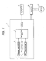
- Fig. 1 is a system structural view in which an exemplary embodiment is applied to a hybrid car;
- Fig. 2 is a block diagram showing an estimate algorithm of the battery remaining capacity;
- Fig. 3 is an explanatory view showing the relationship between the battery capacity and the temperature;
- Fig. 4 is a circuit diagram showing an equivalent circuit model of a battery;
- Fig. 5 is an explanatory view showing the relationship between the reference remaining capacity and the open-circuit voltage;
- Fig. 6 is an explanatory view showing the characteristics of a proportional coefficient;
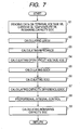
- Fig. 7 is a flow chart of the remaining capacity calculation processing;
- Fig. 8 is an explanatory view of an impedance table;
- Fig. 9 is an explanatory view of a table of reference remaining capacity;
- Fig. 10 is an explanatory view showing the remaining capacity including the constant current error and the final remaining capacity according to the reference remaining capacity.
- Fig. 1 shows an example in which exemplary embodiment of the invention is applied to a hybrid electric vehicle (HEV) running in combination of an engine and a motor.
- a reference numeral 1 is a power supply unit of the HEV.
- the power supply unit 1 includes a battery 2 formed by a plurality of battery packs sealing a plurality of cells, for example, as an electric power storage, connected in series, and a calculation unit (calculation ECU) 3 which calculates the remaining capacity of the battery 2, controls cooling and charge of the battery 2, and performs the energy management such as abnormal detection and a protection operation at the abnormal detection, within one package.
- the calculation method of remaining capacity according to the invention can be applied to an electrochemical capacitor and the other secondary battery.
- the calculation ECU 3 is formed by a microcomputer, which calculates the remaining capacity SOC expressed by the state of charge (State of charge: SOC) of the battery 2, according to the terminal voltage VB of the battery 2 measured by a voltage sensor 4, the charge/discharge current IB of the battery 2 measured by a current sensor 5, and the temperature (cell temperature) TB of the battery 2 measured by a temperature sensor 6, in predetermined intervals of time.
- the remaining capacity SOC is supplied, for example, from the calculation ECU 3 of the power supply unit 1 to an electric control unit for HEV (ECU for HEV) 10 through CAN (Controller Area Network) communication and used as the basic data for vehicle control and the data for display of the battery remaining amount and alarming.
- SOC state of charge
- the ECU for HEV 10 is formed by a microcomputer similarly, which performs a necessary control on the operation of the HEV according to an instruction from an operator. Namely, the ECU for HEV 10 detects the state of a vehicle according to a signal from the power supply unit 1 or a signal from a sort of sensor/switch not illustrated, and controls not only an inverter 20 which converts the DC power of the battery 2 into the AC power to drive a motor 15 but also an engine and an automatic transmission, not illustrated, directly or through an exclusive control unit.
- Calculationof the remaining capacitySOC in the calculation ECU 3 is performed according to the estimate algorithm shown in the block diagram of Fig. 2.
- This estimate algorithm is intended for the remaining capacity SOCV calculated based on the open-circuit voltage VOC of a battery and it calculates the final remaining capacity SOC of the battery 2 through a proportional-integral control with this remaining capacity SOCV used as a target value.
- the remaining capacity based on the open-circuit voltage of the battery is properly referred to as "reference remaining capacity”.
- the remaining capacity of a battery there are a technique of requiring the remaining capacity according to the integrated value of the battery current and a technique of requiring the remaining capacity according to the open-circuit voltage of the battery and the both have each good and bad points.
- the former is tough to load fluctuation caused by incoming current and it can get the stable remaining capacity, however, it has a drawback that there may occur accumulation of current errors easily (error becomes enormous, in particular, at a time of continuous high load). While the latter can get the accurate value in a current stable region, it has, however, a drawback that it cannot get an accurate impedance at a time of estimating an open-circuit voltage and that the calculated value of the remaining capacity easily changes when a load changes rapidly and drastically.
- the calculation ECU 3 is designed to feed back a difference between the reference remaining capacity SOCV and the final remaining capacity SOC based on the battery open-circuit voltage VOC according to the proportional-integral control, hence to require the stable remaining capacity even when a load fluctuates, while securing the accuracy in a current stable region.
- the proportional-integral control of the reference remaining capacity SOCV is mainly used and the remaining capacity based on the current integration is added in a feed-forward way, hence to secure the response ability to the load fluctuation.
- the calculation ECU 3 comprises a current integration remaining capacity calculating unit 3a which calculates the remaining capacity SOCI based on the current integration, a reference remaining capacity calculating unit 3b as reference remaining capacity calculating means which calculates the reference remaining capacity SOCV based on the open-circuit voltage VOC, a capacity difference calculating unit 3c as capacity difference calculating means which calculates a capacity difference ESOC between the final remaining capacity SOC and the reference remaining capacity SOCV as a target value, a proportional-integral controlling unit 3d as proportional-integral controlling means which calculates the proportional correction amount and the integral correction amount of the proportional-integral control based on the capacity difference ESOC, and a remaining capacity calculating unit 3e as remaining capacity calculating means which calculates the final remaining capacity SOC of the battery 2.
- a current integration remaining capacity calculating unit 3a which calculates the remaining capacity SOCI based on the current integration
- a reference remaining capacity calculating unit 3b as reference remaining capacity calculating means which calculates the reference remaining capacity SOCV based on the open
- the remaining capacity SOCI based on the current integration can be required according to the following (1) by using the initial value SOCI(0) as the base value through the battery current IB.
- S O C I S O C I ( 0 ) ⁇ ⁇ [ ( 100 ⁇ ⁇ ⁇ I B / A H ) + S D ] d t / 3600
- the current capacity AH of the battery changes depending on the temperature, as illustrated in Fig. 3, and the battery capacity is decreased according as the temperature becomes lower.
- the current capacity AH is calculated referring to the table.
- the equivalent circuit shown in Fig. 4 is an equivalent circuit model with each parameter for R1 to R3 and each parameter for capacity Cl, CPE1, and CPE2 (where, CPE1 and CPE2 are for double layer capacity) combined in series and in parallel, and each parameter is determined by curve-fitting the known Cole-Cole plot in an alternative current impedance method.
- the impedance Z required from the parameters dramatically changes according to the temperature of the battery, electrochemical reaction speed, and frequency component of charge/discharge current. Therefore, as a parameter which reflects the charge/discharge state of the battery, the change rate of current is used in order to determine the impedance Z.
- the current change rate directly reflects the load fluctuation of the battery, a simple current change rate would receive an influence of spikes rapidly changing. Though the influence by the spikes can be moderated through the processing of the simple average, moving average, and weighted average of the predetermined sampling number, in particular, when considering the delay of current, the use of the moving average is preferable which can reflect the history charge/discharge state of the battery properly not excessively as for a change in the charge/discharge state.
- the current change rate ⁇ IM/ ⁇ t in the time t of the moving average IM is adopted as a replacement for the frequency component, and after the data is accumulated through the impedance measurement under the condition of the current change rate ⁇ IM/ ⁇ t and the battery temperature TB, a table of the impedance Z (an impedance table in Fig. 8 described later) is created according to the temperature TB and the current change rate IM/ ⁇ t, to require the impedance Z referring to this table.
- the internal impedance Z of the battery increases according as the temperature becomes lower, and the current change rate accordingly becomes smaller.
- the impedance Z is determined by using the corrected current change rate TK ⁇ IM/ ⁇ t with the current change rate ⁇ IM/ ⁇ t corrected by the temperature, as mentioned below.
- the reference remaining capacity SOCV is calculated according to the electrochemical relationship within the battery. Specifically, when the relationship between the open-circuit voltage VOC and the reference remaining capacity SOCV is expressed by using the well-known Nernst Equation which describes the relationship between the electrode potential and the ion activity in a state of equilibrium, the following formula (3) can be obtained.
- V O C E + [ ( R g ⁇ T B / N e ⁇ F ) ⁇ 1 n S O V C / ( 100 ⁇ S O C V ) ] + Y
- Rg gas constant (8.314J/mol-K)
- TB battery temperature (absolute temperature K)
- F Faraday constant (96485C/mol)
- Y is a correction factor, representing the quality of voltage-remaining capacity at room temperature by the function of the remaining capacity.
- Y ⁇ 10 ⁇ 6 X 3 + 9 ⁇ 10 ⁇ 5 X 2 + 0.013 X ⁇ 0.7311
- the concrete correlation between the open-circuit voltage VOC and the reference remaining capacity SOCV represented by the above formula (3) varies depending on the type and the quality of a battery, and for example, in a lithium-ion battery, it shows a curve as shown in Fig. 5.
- the relationship between the open-circuit voltage VOC and the reference remaining capacity SOCV shown in Fig. 5 is a correlation represented by a simple curve in which a change of the reference remaining capacity SOCV never becomes flat as for a change of the open-circuit voltage VOC, and knowing the value of the open-circuit voltage VOC can lead to the clearly understanding of the value of the reference remaining capacity SOCV.
- the reference remaining capacity SOCV has a correlation not only to the open-circuit voltage VOC but also to the battery temperature TB, and even when the open-circuit voltage VOC has the same value, as illustrate in Fig. 5, according as the battery temperature TB becomes lower, the reference remaining capacity SOCV decreases.
- the reference remaining capacity SOCV can be directly calculated by using the formula (3), actually, however, it is necessary to consider the charge/discharge characteristic inherent in a battery actually used and the using condition.
- the proportional correction amount (KP ⁇ ESOC) by the proportional coefficient KP and the integral correction amount (KI ⁇ SISOC) by the integral coefficient KI are calculated by using the capacity difference ESOC(k) calculated from the formula (5), and the final remaining capacity SOC (k) is calculated by adding the remaining capacity SOCI (k) based on the current integration according to the above formula (1') to these correction amounts.
- S O C ( k ) K P ⁇ E S O C ( K ) + K I ⁇ S I S O C ( K ) + S O C I ( k )
- SISOC(k) SISOC(k-1)+ESOC(k) ⁇ DLTT
- the proportional coefficient KP and the integral coefficient KI are determined considering the stability and the response ability at a load fluctuation, and in a current stable area, the correction amount by the proportional coefficient KP is chiefly used so that the final remaining capacity SOC may have an agreement with the reference remaining capacity SOCV, while in a large current change area, the correction amount by the integral coefficient KI is chiefly used, hence to restrain the influence of the reference remaining capacity SOCV which is easy to change according to the load fluctuation, to secure the stability.
- the proportional coefficient KP and the integral coefficient KI can be set by using the parameter which reflects the charge/discharge state of a battery, and the proportional coefficient KP, in particular, can be set by using the current change rate ⁇ IM/ ⁇ t and the battery temperature TB through the above-mentioned moving average. For example, a table is previously created through experiment or simulation based on the current change rate ⁇ IM/ ⁇ t and the battery temperature TB and the proportional coefficient KP can be required referring to this table.
- Fig. 6 shows the characteristic of the proportional coefficient KP which varies depending on the current change rate ⁇ IM/ ⁇ t and the battery temperature TB through the moving average.
- the proportional coefficient KP is set at a larger value so that the remaining capacity SOC finally calculated with the larger correction amount based on the capacity difference ESOC may have a good agreement with the reference remaining capacity SOCV of voltage base satisfactorily.
- the proportional coefficient KP is set smaller so as to restrain the vibration of the reference remaining capacity SOCV and to be able to calculate the remaining capacity of accuracy and of a good response ability also at the load fluctuation.
- the proportional coefficient KP is set smaller in order to compensate for an increase in the open-circuit voltage VOC according to a relative increase of the impedance Z, according as the battery temperature TB becomes lower.
- the flow chart of Fig. 7 shows the basic calculation processing of the remaining capacity in the calculation ECU 3 of the power supply unit 1, which is performed in a predetermined time interval (for example, in every 0.1 sec).
- Step S1 data about the terminal voltage VB, the current IB, the temperature TB, and the remaining capacity SOC in the previous one cycle, calculated in the last calculation processing of the battery 2 is read.
- the terminal voltage VB is the average of a plurality of battery packs
- the current IB is the total sum of the currents of the battery packs; and the both data is taken, for example, in every 0.1 sec.
- the temperature TB takes data, for example, in every 10 sec.
- Step S2 moving average is performed on the current IB, hence to obtain the current change rate ⁇ IM/ ⁇ t per time unit.
- the current IB is sampled, for example, in every 0.1 sec and the calculation cycle of current integration is defined as the cycle of 0.5 sec, five data is taken for the moving average of the current IB.
- Step S3 the impedance Z of the battery 2 is calculated referring to the impedance table shown in Fig. 8.
- the impedance table in Fig. 8 includes the impedance Z of the equivalent circuit with the corrected current change rate TK ⁇ IM/ ⁇ t obtained by correcting the current change rate ⁇ IM/ ⁇ t by the temperature and the temperature TB as parameters, and when the corrected current change rate TK ⁇ IM/ ⁇ t is identical, the more the impedance Z increases according as the temperature TB becomes lower, and at the same temperature, the impedance Z is likely to increase according as the corrected current change rate TK ⁇ IM/ ⁇ t becomes smaller.
- Step S4 following Step S3, the calculated impedance Z is used to calculate the open-circuit voltage VOC of the battery 2 according to the above formula (2).
- Step S5 the reference remaining capacity SOCV is calculated referring to the reference remaining capacity table shown in Fig. 9, with the battery temperature TB and the open-circuit voltage VOC as the parameters.
- the reference remaining capacity table shown in Fig. 9 is a table created after understanding the electrochemical state within the battery based on the Nernst Equation, as mentioned above, and schematically, the reference remaining capacity SOCV decreases according as the temperature TB and the open-circuit voltage VOC become lower, while the reference remaining capacity SOCV increases according as the temperature TB and the open-circuit voltage VOC becomes higher.
- Figs. 8 and 9 show the data used in the range under the usual condition and the data in the other range is not described here.
- Step S6 the battery current IB is added up in every calculation cycle DLTT according to the above formula (1'), and the remaining capacity SOCI is calculated according to the current integration.
- Step S7 a capacity difference ESOC between the reference remaining capacity SOCV and the remaining capacity SOC in the previous one control cycle is calculated (refer to the formula (5)), and in Step S8, the proportional correction amount (KP ⁇ ESOC) and the integral correction amount (KI ⁇ SISOC) are calculated according to the proportional-integral control using the proportional coefficient KP and the integral coefficient KI.
- Step S9 according to the above formula (6), the final remaining capacity SOC is calculated and this processing for one cycle is finished.
- the above remaining capacity SOC by the proportional-integral control is shown in Fig. 10, together with the reference remaining capacity SOCV based on the open-circuit voltage VOC of the battery and the remaining capacity SOCI with the battery current IB added up.
- the remaining capacity SOCI indicated by the dotted line in Fig. 10 accumulates the current errors and increases a deviation from the reference remaining capacity SOCV
- the final remaining capacity SOC makes a good agreement with the reference remaining capacity SOCV while controlling the influence of the vibration of the reference remaining capacity SOCV according to the proportional-integral control, and the favorable calculation accuracy and stability can be obtained.
Landscapes
- Physics & Mathematics (AREA)
- General Physics & Mathematics (AREA)
- Secondary Cells (AREA)
- Charge And Discharge Circuits For Batteries Or The Like (AREA)
- Tests Of Electric Status Of Batteries (AREA)
- Electric Propulsion And Braking For Vehicles (AREA)
Abstract
Description
- The present application claims foreign priority based on
Japanese Patent Application No. P.2005-095897, filed on March 29, 2005 - The present invention relates to a remaining capacity calculating device and method for electric power storage which calculates the remaining capacity of an electric power storage such as a secondary battery and an electrochemical capacitor.
- These days, the electric power storages including a secondary battery such as nickel hydride battery and lithium-ion battery and an electrochemical capacitor such as electric double layer capacitor have been improved in downsizing and high energy density, and frequently used as the power source of various devices ranging from an information communication unit like a cell phone to an electric vehicle and a hybrid car.
- In order to make an effective use of the electric power storage, it is important to recognize its remaining capacity accurately, and a technique of requiring the remaining capacity according to the calculation of charge/discharge currents of an electric power storage and a technique of requiring it according to an open-circuit voltage have been known.
- For example,
JP-A-06-242193 -
JP-A-08-179018 -
JP-A-11-223665 - However, the technique of requiring the remaining capacity by adding up the charge/discharge currents and the technique of requiring it according to an open-circuit voltage have each good and bad points. The former is tough to load fluctuation caused by incoming current and it can get the stable remaining capacity, however, it has a drawback that there may occur accumulation of errors easily (error becomes enormous, in particular, at a time of continuous high load), while although the latter can get the accurate value in a current stable region, it has a drawback that the calculated value changes easily when a load changes rapidly and drastically.
- Therefore, only a combination of the both techniques, like
JP-A-06-242193 JP-A-08-179018 JP-A-11-223665 - One or more embodiments of the present invention provide a device and method for calculating a remaining capacity of an electric power storage which can always require a stable and accurate remaining capacity according to the open-circuit voltage of the electric power storage, avoiding the influence of load fluctuation.
- In accordance with one or more embodiments of the present invention, a remaining capacity calculating device for electric power storage is provided with: a reference remaining capacity calculating unit that calculates a remaining capacity based on an open-circuit voltage of an electric power storage as a reference remaining capacity; a capacity difference calculating unit that calculates a capacity difference between the reference remaining capacity calculated by the reference remaining capacity calculating unit and a remaining capacity finally calculated as a remaining capacity of the electric power storage; a proportional-integral controlling unit that calculates a proportional correction amount and an integral correction amount of a proportional-integral control with the reference remaining capacity as a target value, according to the capacity difference; and a remaining capacity calculating unit that calculates the final remaining capacity of the electric power storage, according to the proportional correction amount and the integral correction amount calculated by the proportional-integral controlling unit.
- Further, in the device, the remaining capacity calculating unit may add a remaining capacity based on an integrated value of charge/discharge currents of the electric power storage to the proportional correction amount and the integral correction amount, and may calculate the final remaining capacity of the electric power storage.
- Further, in the device, the proportional-integral controlling unit may calculate the proportional correction amount by multiplying the capacity difference by a coefficient based on a current change rate of the charge/discharge currents of the electric power storage and temperature.
- In accordance with one or more embodiments of the present invention, a remaining capacity calculating method is provided with the steps of: calculating a reference remaining capacity based on an open-circuit voltage; calculating a capacity difference between the reference remaining capacity and a remaining capacity finally calculated as a remaining capacity of the electric power storage; calculating a proportional correction amount and an integral correction amount of a proportional-integral control with the reference remaining capacity as a target value, according to the capacity difference; and calculating the final remaining capacity of the electric power storage, according to the proportional correction amount and the integral correction amount.
- In addition, the method may further provided with the step of: adding a remaining capacity based on an integrated value of charge/discharge currents of the electric power storage to the proportional correction amount and the integral correction amount.
- Further, in the method, the proportional correction amount is calculated by multiplying the capacity difference by a coefficient based on a current change rate of the charge/discharge currents of the electric power storage and temperature.
- According to the remaining capacity calculating device and method for electric power storage of one or more embodiments of the present invention, a remaining capacity can be calculated, always stably and accurately without an influence of load fluctuation, based on the open-circuit voltage of the electric power storage.
- Other aspects and advantages of the invention will be apparent from the following description of embodiments and the appended claims.
- Fig. 1 is a structural view showing an exemplary embodiment in which an embodiments of the invention is applied to a hybrid car.
- Fig. 2 is a block diagram showing the estimate algorithm of the battery remaining capacity.
- Fig. 3 is a view for use in describing the relationship between the battery capacity and the temperature.
- Fig. 4 is a circuit diagram showing the equivalent circuit model of the battery.
- Fig. 5 is a view for use in describing the relationship between the reference remaining capacity and the open-circuit voltage.
- Fig. 6 is a view for use in describing the characteristic of the proportional coefficient.
- Fig. 7 is a flow chart of the remaining capacity calculation processing.
- Fig. 8 is a view for use in describing the impedance table.
- Fig. 9 is a view for use in describing the reference remaining capacity table.
- Fig. 10 is a view for use in describing the final remaining capacity based on the remaining capacity including the constant current errors and the reference remaining capacity.
- Figs. 1 to 10 are concerned with the embodiments of the invention: Fig. 1 is a system structural view in which an exemplary embodiment is applied to a hybrid car; Fig. 2 is a block diagram showing an estimate algorithm of the battery remaining capacity; Fig. 3 is an explanatory view showing the relationship between the battery capacity and the temperature; Fig. 4 is a circuit diagram showing an equivalent circuit model of a battery; Fig. 5 is an explanatory view showing the relationship between the reference remaining capacity and the open-circuit voltage; Fig. 6 is an explanatory view showing the characteristics of a proportional coefficient; Fig. 7 is a flow chart of the remaining capacity calculation processing; Fig. 8 is an explanatory view of an impedance table; Fig. 9 is an explanatory view of a table of reference remaining capacity; and Fig. 10 is an explanatory view showing the remaining capacity including the constant current error and the final remaining capacity according to the reference remaining capacity.
- Fig. 1 shows an example in which exemplary embodiment of the invention is applied to a hybrid electric vehicle (HEV) running in combination of an engine and a motor. In Fig. 1, a
reference numeral 1 is a power supply unit of the HEV. Thepower supply unit 1 includes a battery 2 formed by a plurality of battery packs sealing a plurality of cells, for example, as an electric power storage, connected in series, and a calculation unit (calculation ECU) 3 which calculates the remaining capacity of the battery 2, controls cooling and charge of the battery 2, and performs the energy management such as abnormal detection and a protection operation at the abnormal detection, within one package. - In the embodiment, although the description will be made by taking, by way of example, a rechargeable lithium-ion battery as an electric power storage, the calculation method of remaining capacity according to the invention can be applied to an electrochemical capacitor and the other secondary battery.
- The
calculation ECU 3 is formed by a microcomputer, which calculates the remaining capacity SOC expressed by the state of charge (State of charge: SOC) of the battery 2, according to the terminal voltage VB of the battery 2 measured by avoltage sensor 4, the charge/discharge current IB of the battery 2 measured by acurrent sensor 5, and the temperature (cell temperature) TB of the battery 2 measured by a temperature sensor 6, in predetermined intervals of time. The remaining capacity SOC is supplied, for example, from thecalculation ECU 3 of thepower supply unit 1 to an electric control unit for HEV (ECU for HEV) 10 through CAN (Controller Area Network) communication and used as the basic data for vehicle control and the data for display of the battery remaining amount and alarming. - The ECU for
HEV 10 is formed by a microcomputer similarly, which performs a necessary control on the operation of the HEV according to an instruction from an operator. Namely, the ECU forHEV 10 detects the state of a vehicle according to a signal from thepower supply unit 1 or a signal from a sort of sensor/switch not illustrated, and controls not only aninverter 20 which converts the DC power of the battery 2 into the AC power to drive amotor 15 but also an engine and an automatic transmission, not illustrated, directly or through an exclusive control unit. - Calculationof the remaining capacitySOC in the
calculation ECU 3 is performed according to the estimate algorithm shown in the block diagram of Fig. 2. This estimate algorithm is intended for the remaining capacity SOCV calculated based on the open-circuit voltage VOC of a battery and it calculates the final remaining capacity SOC of the battery 2 through a proportional-integral control with this remaining capacity SOCV used as a target value. Hereinafter, the remaining capacity based on the open-circuit voltage of the battery is properly referred to as "reference remaining capacity". - Generally, as a technique of calculating the remaining capacity of a battery, there are a technique of requiring the remaining capacity according to the integrated value of the battery current and a technique of requiring the remaining capacity according to the open-circuit voltage of the battery and the both have each good and bad points. The former is tough to load fluctuation caused by incoming current and it can get the stable remaining capacity, however, it has a drawback that there may occur accumulation of current errors easily (error becomes enormous, in particular, at a time of continuous high load). While the latter can get the accurate value in a current stable region, it has, however, a drawback that it cannot get an accurate impedance at a time of estimating an open-circuit voltage and that the calculated value of the remaining capacity easily changes when a load changes rapidly and drastically.
- The
calculation ECU 3 is designed to feed back a difference between the reference remaining capacity SOCV and the final remaining capacity SOC based on the battery open-circuit voltage VOC according to the proportional-integral control, hence to require the stable remaining capacity even when a load fluctuates, while securing the accuracy in a current stable region. In the embodiment, the proportional-integral control of the reference remaining capacity SOCV is mainly used and the remaining capacity based on the current integration is added in a feed-forward way, hence to secure the response ability to the load fluctuation. - As each function of forming the SOC estimate algorithm, the
calculation ECU 3 comprises a current integration remaining capacity calculating unit 3a which calculates the remaining capacity SOCI based on the current integration, a reference remainingcapacity calculating unit 3b as reference remaining capacity calculating means which calculates the reference remaining capacity SOCV based on the open-circuit voltage VOC, a capacity difference calculating unit 3c as capacity difference calculating means which calculates a capacity difference ESOC between the final remaining capacity SOC and the reference remaining capacity SOCV as a target value, a proportional-integral controllingunit 3d as proportional-integral controlling means which calculates the proportional correction amount and the integral correction amount of the proportional-integral control based on the capacity difference ESOC, and a remainingcapacity calculating unit 3e as remaining capacity calculating means which calculates the final remaining capacity SOC of the battery 2. - More specifically, the remaining capacity SOCI based on the current integration can be required according to the following (1) by using the initial value SOCI(0) as the base value through the battery current IB.

where, η : current efficiency
AH : current capacity (variable by temperature)
SD : self-discharge rate - The current efficiency η and the self-discharge rate SD are respectively regarded as a constant in the lithium-ion battery of the embodiment and practically, they are η=1 and SD=0. Since the formula (1) represented by the continuous time series is calculated in the periodical calculation processing, it is made discrete by the calculation cycle DLTT in every sampling time k and simplified into the following formula (1'). Where, the initial value SOCI(0) is set to be the reference remaining capacity SOCV read at a system activation.

- The current capacity AH of the battery changes depending on the temperature, as illustrated in Fig. 3, and the battery capacity is decreased according as the temperature becomes lower. After a table, for example, with the temperature TB as parameter, is created, the current capacity AH is calculated referring to the table.
- While, as for the reference remaining capacity SOCV based on the open-circuit voltage VOC of the battery, an accurate calculated value is obtained by grasping the internal state of the battery electrochemically according to the battery theory. In order to require this reference remaining capacity SOCV, at first, the internal impedance Z of the battery is required by using the equivalent circuit model shown in Fig. 4.
- The equivalent circuit shown in Fig. 4 is an equivalent circuit model with each parameter for R1 to R3 and each parameter for capacity Cl, CPE1, and CPE2 (where, CPE1 and CPE2 are for double layer capacity) combined in series and in parallel, and each parameter is determined by curve-fitting the known Cole-Cole plot in an alternative current impedance method.
- The impedance Z required from the parameters dramatically changes according to the temperature of the battery, electrochemical reaction speed, and frequency component of charge/discharge current. Therefore, as a parameter which reflects the charge/discharge state of the battery, the change rate of current is used in order to determine the impedance Z. Although the current change rate directly reflects the load fluctuation of the battery, a simple current change rate would receive an influence of spikes rapidly changing. Though the influence by the spikes can be moderated through the processing of the simple average, moving average, and weighted average of the predetermined sampling number, in particular, when considering the delay of current, the use of the moving average is preferable which can reflect the history charge/discharge state of the battery properly not excessively as for a change in the charge/discharge state.
- When the moving average of the battery current is defined as IM, the current change rate ΔIM/Δt in the time t of the moving average IM is adopted as a replacement for the frequency component, and after the data is accumulated through the impedance measurement under the condition of the current change rate ΔIM/Δt and the battery temperature TB, a table of the impedance Z (an impedance table in Fig. 8 described later) is created according to the temperature TB and the current change rate IM/Δ t, to require the impedance Z referring to this table.
- The internal impedance Z of the battery increases according as the temperature becomes lower, and the current change rate accordingly becomes smaller. Directly speaking, the impedance Z is determined by using the corrected current change rate TKΔIM/Δt with the current change rate ΔIM/Δt corrected by the temperature, as mentioned below.
- The impedance Z required from the table, the terminal voltage VB measured by the
voltage sensor 4, and the current IB measured by thecurrent sensor 5 are applied to the following formula (2) representing the relation with the open-circuit voltage VOC, hence to require the open-circuit voltage VOC.
- After the open-circuit voltage VOC is estimated, the reference remaining capacity SOCV is calculated according to the electrochemical relationship within the battery. Specifically, when the relationship between the open-circuit voltage VOC and the reference remaining capacity SOCV is expressed by using the well-known Nernst Equation which describes the relationship between the electrode potential and the ion activity in a state of equilibrium, the following formula (3) can be obtained.

Where, E: standard electrode potential (in the lithium-ion battery of this embodiment, E=3.745)
Rg: gas constant (8.314J/mol-K)
TB: battery temperature (absolute temperature K)
Ne: the number of ions (in the lithium-ion battery of the embodiment, Ne=1)
F : Faraday constant (96485C/mol) - In the formula (3), Y is a correction factor, representing the quality of voltage-remaining capacity at room temperature by the function of the remaining capacity. When SOCV=X, it can be represented by the cubic function of SOCV, as shown in the following formula (4).

- The concrete correlation between the open-circuit voltage VOC and the reference remaining capacity SOCV represented by the above formula (3) varies depending on the type and the quality of a battery, and for example, in a lithium-ion battery, it shows a curve as shown in Fig. 5. The relationship between the open-circuit voltage VOC and the reference remaining capacity SOCV shown in Fig. 5 is a correlation represented by a simple curve in which a change of the reference remaining capacity SOCV never becomes flat as for a change of the open-circuit voltage VOC, and knowing the value of the open-circuit voltage VOC can lead to the clearly understanding of the value of the reference remaining capacity SOCV.
- The reference remaining capacity SOCV has a correlation not only to the open-circuit voltage VOC but also to the battery temperature TB, and even when the open-circuit voltage VOC has the same value, as illustrate in Fig. 5, according as the battery temperature TB becomes lower, the reference remaining capacity SOCV decreases. In this case, with the open-circuit voltage VOC and the battery temperature TB as parameters, the reference remaining capacity SOCV can be directly calculated by using the formula (3), actually, however, it is necessary to consider the charge/discharge characteristic inherent in a battery actually used and the using condition.
- When the actual battery state is understood from the above formula (3), with the SOCV-VOC characteristic at room temperature as reference, charge/discharge test or simulation in each temperature area is performed and the actual data is accumulated. A table of reference remaining capacity SOCV (reference remaining capacity table of Fig. 9 described later), with the open-circuit voltage VOC and the battery temperature TB as parameters, is created from the accumulated actual data and the reference remaining capacity SOCV is required by using this table.
- After the reference remaining capacity SOCV is required, a proportional-integral control is performed with this reference remaining capacity SOCV as the target value. As illustrated in the following formula (5), a capacity difference ESOC(k) between the reference remaining capacity SOCV(K) in a predetermined calculation cycle and the remaining capacity SOC(k) in the previous one cycle is calculated.

- As illustrated in the following formula (6), the proportional correction amount (KP×ESOC) by the proportional coefficient KP and the integral correction amount (KI×SISOC) by the integral coefficient KI are calculated by using the capacity difference ESOC(k) calculated from the formula (5), and the final remaining capacity SOC (k) is calculated by adding the remaining capacity SOCI (k) based on the current integration according to the above formula (1') to these correction amounts.

- Where, SISOC(k) = SISOC(k-1)+ESOC(k)×DLTT
- The proportional coefficient KP and the integral coefficient KI are determined considering the stability and the response ability at a load fluctuation, and in a current stable area, the correction amount by the proportional coefficient KP is chiefly used so that the final remaining capacity SOC may have an agreement with the reference remaining capacity SOCV, while in a large current change area, the correction amount by the integral coefficient KI is chiefly used, hence to restrain the influence of the reference remaining capacity SOCV which is easy to change according to the load fluctuation, to secure the stability.
- The proportional coefficient KP and the integral coefficient KI can be set by using the parameter which reflects the charge/discharge state of a battery, and the proportional coefficient KP, in particular, can be set by using the current change rate ΔIM/Δt and the battery temperature TB through the above-mentioned moving average. For example, a table is previously created through experiment or simulation based on the current change rate ΔIM/Δt and the battery temperature TB and the proportional coefficient KP can be required referring to this table.
- Fig. 6 shows the characteristic of the proportional coefficient KP which varies depending on the current change rate ΔIM/Δt and the battery temperature TB through the moving average. In a stable state where the load fluctuation of the battery is small (ΔIM/Δt is small and the current change is small), the proportional coefficient KP is set at a larger value so that the remaining capacity SOC finally calculated with the larger correction amount based on the capacity difference ESOC may have a good agreement with the reference remaining capacity SOCV of voltage base satisfactorily.
- On the contrary, in a state of large load fluctuation (ΔIM/Δt is larger and the current change is greater), the proportional coefficient KP is set smaller so as to restrain the vibration of the reference remaining capacity SOCV and to be able to calculate the remaining capacity of accuracy and of a good response ability also at the load fluctuation. As for the identical current change rate ΔIM/Δt, the proportional coefficient KP is set smaller in order to compensate for an increase in the open-circuit voltage VOC according to a relative increase of the impedance Z, according as the battery temperature TB becomes lower.
- This can obtain an accurate remaining capacity SOC, making use of a good point of the reference remaining capacity SOCV based on the open-circuit voltage, grasping the charge/discharge state of the battery more accurately, avoid the accumulation of errors by the current integration, and assure the stability when there occurs a disturbance.
- The calculation processing of the remaining capacity SOC through the proportional-integral control on the above reference remaining capacity SOCV will be described by using the flow chart of Fig. 7.
- The flow chart of Fig. 7 shows the basic calculation processing of the remaining capacity in the
calculation ECU 3 of thepower supply unit 1, which is performed in a predetermined time interval (for example, in every 0.1 sec). Upon a start of this processing, at first, in Step S1, data about the terminal voltage VB, the current IB, the temperature TB, and the remaining capacity SOC in the previous one cycle, calculated in the last calculation processing of the battery 2 is read. Assume that the terminal voltage VB is the average of a plurality of battery packs, the current IB is the total sum of the currents of the battery packs; and the both data is taken, for example, in every 0.1 sec. Further, assume that the temperature TB takes data, for example, in every 10 sec. - Proceeding to Step S2, moving average is performed on the current IB, hence to obtain the current change rate ΔIM/Δt per time unit. When the current IB is sampled, for example, in every 0.1 sec and the calculation cycle of current integration is defined as the cycle of 0.5 sec, five data is taken for the moving average of the current IB. Further, in Step S3, the impedance Z of the battery 2 is calculated referring to the impedance table shown in Fig. 8.
- The impedance table in Fig. 8 includes the impedance Z of the equivalent circuit with the corrected current change rate TKΔIM/Δt obtained by correcting the current change rate ΔIM/Δt by the temperature and the temperature TB as parameters, and when the corrected current change rate TKΔIM/Δt is identical, the more the impedance Z increases according as the temperature TB becomes lower, and at the same temperature, the impedance Z is likely to increase according as the corrected current change rate TKΔIM/Δt becomes smaller.
- In Step S4 following Step S3, the calculated impedance Z is used to calculate the open-circuit voltage VOC of the battery 2 according to the above formula (2). In Step S5, the reference remaining capacity SOCV is calculated referring to the reference remaining capacity table shown in Fig. 9, with the battery temperature TB and the open-circuit voltage VOC as the parameters.
- The reference remaining capacity table shown in Fig. 9 is a table created after understanding the electrochemical state within the battery based on the Nernst Equation, as mentioned above, and schematically, the reference remaining capacity SOCV decreases according as the temperature TB and the open-circuit voltage VOC become lower, while the reference remaining capacity SOCV increases according as the temperature TB and the open-circuit voltage VOC becomes higher. Figs. 8 and 9 show the data used in the range under the usual condition and the data in the other range is not described here.
- Proceeding to Step S6, the battery current IB is added up in every calculation cycle DLTT according to the above formula (1'), and the remaining capacity SOCI is calculated according to the current integration. In Step S7, a capacity difference ESOC between the reference remaining capacity SOCV and the remaining capacity SOC in the previous one control cycle is calculated (refer to the formula (5)), and in Step S8, the proportional correction amount (KP×ESOC) and the integral correction amount (KI×SISOC) are calculated according to the proportional-integral control using the proportional coefficient KP and the integral coefficient KI. In Step S9, according to the above formula (6), the final remaining capacity SOC is calculated and this processing for one cycle is finished.
- The above remaining capacity SOC by the proportional-integral control is shown in Fig. 10, together with the reference remaining capacity SOCV based on the open-circuit voltage VOC of the battery and the remaining capacity SOCI with the battery current IB added up. Although the remaining capacity SOCI indicated by the dotted line in Fig. 10 accumulates the current errors and increases a deviation from the reference remaining capacity SOCV, the final remaining capacity SOC makes a good agreement with the reference remaining capacity SOCV while controlling the influence of the vibration of the reference remaining capacity SOCV according to the proportional-integral control, and the favorable calculation accuracy and stability can be obtained.
- It will be apparent to those skilled in the art that various modifications and variations can be made to the described preferred embodiments of the present invention without departing from the spirit or scope of the invention. Thus, it is intended that the present invention cover all modifications and variations of this invention consistent with the scope of the appended claims and their equivalents.
Claims (6)
- A remaining capacity calculating device for electric power storage, the device comprising:a reference remaining capacity calculating unit that calculates a remaining capacity based on an open-circuit voltage of an electric power storage as a reference remaining capacity;a capacity difference calculating unit that calculates a capacity difference between the reference remaining capacity calculated by the reference remaining capacity calculating unit and a remaining capacity finally calculated as a remaining capacity of the electric power storage;a proportional-integral controlling unit that calculates a proportional correction amount and an integral correction amount of a proportional-integral control with the reference remaining capacity as a target value, according to the capacity difference; anda remaining capacity calculating unit that calculates the final remaining capacity of the electric power storage, according to the proportional correction amount and the integral correction amount calculated by the proportional-integral controlling unit.
- The device according to claim 1, wherein the remaining capacity calculating unit adds a remaining capacity based on an integrated value of charge/discharge currents of the electric power storage to the proportional correction amount and the integral correction amount, and calculates the final remaining capacity of the electric power storage.
- The device according to claim 1 or 2, wherein the proportional-integral controlling unit calculates the proportional correction amount by multiplying the capacity difference by a coefficient based on a current change rate of the charge/discharge currents of the electric power storage and temperature.
- A remaining capacity calculating method for electric power storage, the method comprising:calculating a reference remaining capacity based on an open-circuit voltage;calculating a capacity difference between the reference remaining capacity and a remaining capacity finally calculated as a remaining capacity of the electric power storage;calculating a proportional correction amount and an integral correction amount of a proportional-integral control with the reference remaining capacity as a target value, according to the capacity difference; andcalculating the final remaining capacity of the electric power storage, according to the proportional correction amount and the integral correction amount.
- The method according to claim 4, further comprising:adding a remaining capacity based on an integrated value of charge/discharge currents of the electric power storage to the proportional correction amount and the integral correction amount.
- The method according to claim 4 or 5, wherein the proportional correction amount is calculated by multiplying the capacity difference by a coefficient based on a current change rate of the charge/discharge currents of the electric power storage and temperature.
Applications Claiming Priority (1)
| Application Number | Priority Date | Filing Date | Title |
|---|---|---|---|
| JP2005095897A JP4571000B2 (en) | 2005-03-29 | 2005-03-29 | Remaining capacity calculation device for power storage device |
Publications (2)
| Publication Number | Publication Date |
|---|---|
| EP1707974A1 true EP1707974A1 (en) | 2006-10-04 |
| EP1707974B1 EP1707974B1 (en) | 2010-07-21 |
Family
ID=36646107
Family Applications (1)
| Application Number | Title | Priority Date | Filing Date |
|---|---|---|---|
| EP06006416A Ceased EP1707974B1 (en) | 2005-03-29 | 2006-03-28 | Remaining capacity calculating device and method for electric power storage |
Country Status (4)
| Country | Link |
|---|---|
| US (1) | US7362076B2 (en) |
| EP (1) | EP1707974B1 (en) |
| JP (1) | JP4571000B2 (en) |
| DE (1) | DE602006015558D1 (en) |
Cited By (8)
| Publication number | Priority date | Publication date | Assignee | Title |
|---|---|---|---|---|
| EP2001074A1 (en) * | 2007-06-07 | 2008-12-10 | Peugeot Citroen Automobiles SA | System and method to determine the loss in capacity and energy of a battery determining the output capacity of a battery |
| EP2233939A4 (en) * | 2008-01-11 | 2010-12-29 | Sk Energy Co Ltd | METHOD AND DEVICE FOR MEASURING CHARGE STATUS (SOC) IN A BATTERY MANAGEMENT SYSTEM |
| WO2012150405A1 (en) * | 2011-05-05 | 2012-11-08 | Renault S.A.S. | Method for processing a signal quantifying the state of charge of an electric battery of a motor vehicle in time |
| WO2013037307A1 (en) * | 2011-09-15 | 2013-03-21 | Mediatek Inc. | System and methods for determining remaining battery capacity of battery device |
| WO2014102021A1 (en) * | 2012-12-27 | 2014-07-03 | Robert Bosch Gmbh | Method for determining a charge state |
| EP2439550A4 (en) * | 2009-06-03 | 2014-07-16 | Mitsubishi Heavy Ind Ltd | DEVICE FOR CALCULATING THE CHARGING STATUS OF A BATTERY |
| US10042004B2 (en) | 2015-02-12 | 2018-08-07 | Mediatek Inc. | Apparatus used with processor of portable device and arranged for performing at least one part of fuel gauge operation for battery by using hardware circuit element(s) when processor enter sleep mode |
| CN113199946A (en) * | 2020-12-11 | 2021-08-03 | 广东电网有限责任公司电力调度控制中心 | Electric automobile energy storage polymerization modeling method based on Markov process |
Families Citing this family (43)
| Publication number | Priority date | Publication date | Assignee | Title |
|---|---|---|---|---|
| KR100804697B1 (en) * | 2006-08-11 | 2008-02-18 | 삼성에스디아이 주식회사 | Battery Management System and Its Driving Method |
| US8055343B2 (en) | 2006-10-20 | 2011-11-08 | Cardiac Pacemakers, Inc. | Dynamic battery management in an implantable device |
| JP4884945B2 (en) * | 2006-11-30 | 2012-02-29 | 三菱重工業株式会社 | Charging state prediction program, overhead line-less traffic system and charging method thereof |
| JP5000765B2 (en) * | 2007-12-13 | 2012-08-15 | カーディアック ペースメイカーズ, インコーポレイテッド | Battery consumption detection system and battery consumption detection method in an embedded device |
| KR100962856B1 (en) | 2008-04-03 | 2010-06-09 | 현대자동차주식회사 | How to estimate remaining battery capacity |
| US8868187B2 (en) * | 2008-06-17 | 2014-10-21 | Cardiac Pacemakers, Inc. | Battery depth of discharge in an implantable device |
| JP5159498B2 (en) * | 2008-07-29 | 2013-03-06 | 三洋電機株式会社 | Charge / discharge control method for battery in power supply device of hybrid car |
| DE102009045526A1 (en) * | 2009-10-09 | 2011-04-14 | SB LiMotive Company Ltd., Suwon | Method for initialization and operation of a battery management system |
| ES2645039T3 (en) * | 2009-10-19 | 2017-12-01 | Nuvera Fuel Cells, LLC | Method of managing the state of charge of a battery |
| TWI394972B (en) * | 2009-11-25 | 2013-05-01 | Htc Corp | Method and system for estimating battery percentage |
| WO2011068025A1 (en) * | 2009-12-04 | 2011-06-09 | Semiconductor Energy Laboratory Co., Ltd. | Dc converter circuit and power supply circuit |
| DE102010006965A1 (en) * | 2010-02-05 | 2011-08-11 | Continental Automotive GmbH, 30165 | Apparatus and method for determining a range of a battery characteristic |
| EP2541266B1 (en) * | 2010-02-24 | 2014-07-16 | Mitsubishi Heavy Industries, Ltd. | Charging-rate computation system |
| CN102262216B (en) * | 2010-05-29 | 2014-03-19 | 比亚迪股份有限公司 | Electric quantity detection method for chargeable battery and apparatus thereof |
| KR101191624B1 (en) * | 2010-10-13 | 2012-10-17 | 삼성에스디아이 주식회사 | BATTERY MANAGEMENT SYSTEM AND METHOD OF ESTIMATING BATTERY SOCstate of charge USING THE SAME |
| US8525519B2 (en) * | 2010-11-30 | 2013-09-03 | GM Global Technology Operations LLC | Algorithm for determining the capacity of a battery while in service |
| WO2012169061A1 (en) * | 2011-06-10 | 2012-12-13 | 日立ビークルエナジー株式会社 | Battery control device and battery system |
| KR101863036B1 (en) * | 2011-11-30 | 2018-06-01 | 주식회사 실리콘웍스 | Method for estimating the state of charge of battery and battery management system |
| JP6065561B2 (en) | 2012-03-08 | 2017-01-25 | 日産自動車株式会社 | Secondary battery control device and SOC detection method |
| JP6135110B2 (en) * | 2012-03-08 | 2017-05-31 | 日産自動車株式会社 | Secondary battery control device, charge control method, and SOC detection method |
| FR2994339B1 (en) * | 2012-08-06 | 2014-09-12 | Commissariat Energie Atomique | METHOD FOR MANAGING AND DIAGNOSING A BATTERY |
| KR101547006B1 (en) * | 2012-10-26 | 2015-08-24 | 주식회사 엘지화학 | Apparatus and method for estimating state of charging of battery |
| US9128159B2 (en) * | 2012-12-12 | 2015-09-08 | GM Global Technology Operations LLC | Plug-in charge capacity estimation method for lithium iron-phosphate batteries |
| KR102080632B1 (en) * | 2013-10-28 | 2020-04-14 | 현대모비스 주식회사 | Battery management system and its operating method |
| US9381825B2 (en) * | 2014-02-20 | 2016-07-05 | Ford Global Technologies, Llc | State of charge quality based cell balancing control |
| US9718455B2 (en) * | 2014-02-20 | 2017-08-01 | Ford Global Technologies, Llc | Active battery parameter identification using conditional extended kalman filter |
| US9272634B2 (en) * | 2014-02-20 | 2016-03-01 | Ford Global Technologies, Llc | Active battery system estimation request generation |
| CN103823189B (en) * | 2014-02-25 | 2016-06-08 | 宁德时代新能源科技股份有限公司 | Method for calculating residual capacity of power battery pack |
| CN104198947A (en) * | 2014-09-02 | 2014-12-10 | 奇瑞汽车股份有限公司 | System and method for estimating surplus capacity of lithium ion battery |
| JP2017168422A (en) * | 2016-03-15 | 2017-09-21 | 東洋ゴム工業株式会社 | Method and system for predicting remaining capacity of sealed secondary battery |
| CN107219469A (en) * | 2016-11-17 | 2017-09-29 | 深圳市海盈科技股份有限公司 | Suitable for the continuation of the journey power predicating method of unmanned machine battery |
| CN111366865B (en) * | 2020-03-25 | 2023-04-21 | 松下电器机电(中国)有限公司 | Calculation method for battery health degree |
| CN111289906B (en) * | 2020-04-02 | 2021-11-26 | 辽宁工业大学 | Power battery SOC estimation method |
| CN112698209B (en) * | 2020-12-15 | 2023-09-29 | 西安奇点能源股份有限公司 | A method for SOC terminal calibration of battery energy storage system |
| US12126204B2 (en) * | 2021-03-16 | 2024-10-22 | China Energy Investment Corporation Limited | Battery management unit to determine updated SOC and energy reading, energy storage system comprising, the same, and method of using the same |
| CN113514770A (en) * | 2021-05-14 | 2021-10-19 | 江苏欧力特能源科技有限公司 | Lithium battery residual capacity SOC prediction algorithm based on open-circuit voltage and battery temperature drive |
| CN113484771A (en) * | 2021-07-01 | 2021-10-08 | 昆明理工大学 | Method for estimating wide-temperature full-life SOC and capacity of lithium ion battery |
| CN115575829B (en) * | 2021-07-06 | 2025-10-10 | 广州汽车集团股份有限公司 | A lithium battery power display method and system |
| CN114397587B (en) * | 2022-01-13 | 2025-08-08 | 上海瑞浦青创新能源有限公司 | Method, device and readable storage medium for estimating remaining power of battery system |
| CN115946572B (en) * | 2022-11-21 | 2023-06-30 | 上海玫克生储能科技有限公司 | Battery module capacity calculation and compensation control method, system, equipment and medium |
| CN117420457B (en) * | 2023-11-07 | 2025-07-01 | 江苏正力新能电池技术股份有限公司 | Consistency selection method and device for batteries |
| CN119001493B (en) * | 2024-10-18 | 2025-03-11 | 珠海格力钛电器有限公司 | Method and device for determining available capacity of battery cluster, storage medium and electronic equipment |
| CN120630004B (en) * | 2025-08-15 | 2025-11-04 | 华夏天信智能物联股份有限公司 | A method for estimating the state of charge based on virtual incremental injection |
Citations (2)
| Publication number | Priority date | Publication date | Assignee | Title |
|---|---|---|---|---|
| JP2003149307A (en) * | 2001-11-16 | 2003-05-21 | Toyota Motor Corp | Battery remaining capacity calculation method |
| US20030097225A1 (en) * | 2001-11-16 | 2003-05-22 | Ishishita Teruo | State of charge calculation device and state of charge calculation method |
Family Cites Families (7)
| Publication number | Priority date | Publication date | Assignee | Title |
|---|---|---|---|---|
| JPH06242193A (en) | 1993-02-23 | 1994-09-02 | Toyota Motor Corp | Remaining capacity meter |
| JP3371588B2 (en) | 1994-12-26 | 2003-01-27 | 日産自動車株式会社 | Remaining battery capacity display |
| JPH11223665A (en) | 1998-02-04 | 1999-08-17 | Nissan Motor Co Ltd | Battery remaining capacity calculator |
| KR100425352B1 (en) * | 1998-05-28 | 2004-03-31 | 도요다 지도샤 가부시끼가이샤 | Apparatus for estimating charged state of battery and method for estimating degraded state of battery |
| JP3879278B2 (en) * | 1998-11-10 | 2007-02-07 | 日産自動車株式会社 | Charge amount calculation method and charge amount calculation device for hybrid vehicle |
| JP3864590B2 (en) * | 1998-11-25 | 2007-01-10 | トヨタ自動車株式会社 | Battery charge state detection device |
| JP2002189066A (en) * | 2000-12-22 | 2002-07-05 | Hitachi Ltd | Battery level estimation method |
-
2005
- 2005-03-29 JP JP2005095897A patent/JP4571000B2/en not_active Expired - Fee Related
-
2006
- 2006-03-27 US US11/389,098 patent/US7362076B2/en not_active Expired - Fee Related
- 2006-03-28 DE DE602006015558T patent/DE602006015558D1/en not_active Expired - Lifetime
- 2006-03-28 EP EP06006416A patent/EP1707974B1/en not_active Ceased
Patent Citations (2)
| Publication number | Priority date | Publication date | Assignee | Title |
|---|---|---|---|---|
| JP2003149307A (en) * | 2001-11-16 | 2003-05-21 | Toyota Motor Corp | Battery remaining capacity calculation method |
| US20030097225A1 (en) * | 2001-11-16 | 2003-05-22 | Ishishita Teruo | State of charge calculation device and state of charge calculation method |
Non-Patent Citations (1)
| Title |
|---|
| PATENT ABSTRACTS OF JAPAN vol. 2003, no. 09 3 September 2003 (2003-09-03) * |
Cited By (16)
| Publication number | Priority date | Publication date | Assignee | Title |
|---|---|---|---|---|
| FR2917178A1 (en) * | 2007-06-07 | 2008-12-12 | Peugeot Citroen Automobiles Sa | SYSTEM AND METHOD FOR DETERMINING THE LOSS OF CAPACITY AND ENERGY OF A BATTERY. |
| EP2001074A1 (en) * | 2007-06-07 | 2008-12-10 | Peugeot Citroen Automobiles SA | System and method to determine the loss in capacity and energy of a battery determining the output capacity of a battery |
| US8548761B2 (en) | 2008-01-11 | 2013-10-01 | Sk Innovation Co., Ltd. | Method for measuring SOC of a battery management system and the apparatus thereof |
| EP2233939A4 (en) * | 2008-01-11 | 2010-12-29 | Sk Energy Co Ltd | METHOD AND DEVICE FOR MEASURING CHARGE STATUS (SOC) IN A BATTERY MANAGEMENT SYSTEM |
| EP2233938A4 (en) * | 2008-01-11 | 2010-12-29 | Sk Energy Co Ltd | METHOD AND DEVICE FOR CHARGE STATUS (SOC) OF A BATTERY IN A BATTERY MANAGEMENT SYSTEM |
| US8994334B2 (en) | 2009-06-03 | 2015-03-31 | Mitsubishi Heavy Industries, Ltd. | Battery state-of-charge calculation device |
| EP2439550A4 (en) * | 2009-06-03 | 2014-07-16 | Mitsubishi Heavy Ind Ltd | DEVICE FOR CALCULATING THE CHARGING STATUS OF A BATTERY |
| CN103608691A (en) * | 2011-05-05 | 2014-02-26 | 雷诺股份公司 | Method for timely processing of signals quantifying the state of charge of a motor vehicle battery |
| FR2974921A1 (en) * | 2011-05-05 | 2012-11-09 | Renault Sas | METHOD FOR PROCESSING A SIGNAL THAT QUANTIFIES THE CHARGING CONDITION OF AN ELECTRIC BATTERY OF A MOTOR VEHICLE ACCORDING TO TIME |
| WO2012150405A1 (en) * | 2011-05-05 | 2012-11-08 | Renault S.A.S. | Method for processing a signal quantifying the state of charge of an electric battery of a motor vehicle in time |
| CN103608691B (en) * | 2011-05-05 | 2017-02-01 | 雷诺股份公司 | Method for timely processing of signals quantifying the state of charge of a motor vehicle battery |
| WO2013037307A1 (en) * | 2011-09-15 | 2013-03-21 | Mediatek Inc. | System and methods for determining remaining battery capacity of battery device |
| WO2014102021A1 (en) * | 2012-12-27 | 2014-07-03 | Robert Bosch Gmbh | Method for determining a charge state |
| US10042004B2 (en) | 2015-02-12 | 2018-08-07 | Mediatek Inc. | Apparatus used with processor of portable device and arranged for performing at least one part of fuel gauge operation for battery by using hardware circuit element(s) when processor enter sleep mode |
| CN113199946A (en) * | 2020-12-11 | 2021-08-03 | 广东电网有限责任公司电力调度控制中心 | Electric automobile energy storage polymerization modeling method based on Markov process |
| CN113199946B (en) * | 2020-12-11 | 2023-06-20 | 广东电网有限责任公司电力调度控制中心 | A Markov Process-Based Modeling Method for Electric Vehicle Energy Storage Aggregation |
Also Published As
| Publication number | Publication date |
|---|---|
| US20060220619A1 (en) | 2006-10-05 |
| US7362076B2 (en) | 2008-04-22 |
| DE602006015558D1 (en) | 2010-09-02 |
| JP4571000B2 (en) | 2010-10-27 |
| EP1707974B1 (en) | 2010-07-21 |
| JP2006275797A (en) | 2006-10-12 |
Similar Documents
| Publication | Publication Date | Title |
|---|---|---|
| EP1707974B1 (en) | Remaining capacity calculating device and method for electric power storage | |
| EP1688754B1 (en) | Battery management apparatus | |
| EP1555537B1 (en) | Battery remaining capacity measuring apparatus | |
| EP2321663B1 (en) | Apparatus and method for estimating state of health of battery based on battery voltage variation pattern | |
| EP2700966B1 (en) | Apparatus and method for estimating battery state | |
| EP2181339B1 (en) | Apparatus for estimating open circuit voltage of battery, apparatus for estimating state of charge of battery, and method for controlling the same | |
| US8008891B2 (en) | Simple method for accurately determining a state of charge of a battery, a battery management system using same, and a driving method thereof | |
| JP4864383B2 (en) | Deterioration state estimation device for power storage device | |
| EP2442126A2 (en) | Battery management system and method of estimating battery state of charge | |
| EP4152022B1 (en) | Method for determining full-charge capacity of battery pack, method for determining state of health of battery pack, system, and apparatus | |
| JP4509670B2 (en) | Remaining capacity calculation device for power storage device | |
| JP2007024687A (en) | Battery management system | |
| EP1835297B1 (en) | A method and device for determining characteristics of an unknown battery | |
| JP4570918B2 (en) | Remaining capacity calculation device for power storage device | |
| JP4519523B2 (en) | Remaining capacity calculation device for power storage device | |
| JP4509674B2 (en) | Remaining capacity calculation device for power storage device | |
| JP2006030080A (en) | Remaining capacity calculation device for power storage device | |
| JP4519551B2 (en) | Remaining capacity calculation device for power storage device | |
| JP2006226788A (en) | Battery management system | |
| JP4638175B2 (en) | Remaining capacity display device for power storage device | |
| JP4519518B2 (en) | Remaining capacity calculation device for power storage device | |
| JP4519524B2 (en) | Remaining capacity calculation device for power storage device | |
| JP2005341759A (en) | Hybrid vehicle battery management device | |
| JP2005326377A (en) | Power amount calculation device for power storage device |
Legal Events
| Date | Code | Title | Description |
|---|---|---|---|
| PUAI | Public reference made under article 153(3) epc to a published international application that has entered the european phase |
Free format text: ORIGINAL CODE: 0009012 |
|
| AK | Designated contracting states |
Kind code of ref document: A1 Designated state(s): AT BE BG CH CY CZ DE DK EE ES FI FR GB GR HU IE IS IT LI LT LU LV MC NL PL PT RO SE SI SK TR |
|
| AX | Request for extension of the european patent |
Extension state: AL BA HR MK YU |
|
| 17P | Request for examination filed |
Effective date: 20070111 |
|
| AKX | Designation fees paid |
Designated state(s): DE |
|
| GRAP | Despatch of communication of intention to grant a patent |
Free format text: ORIGINAL CODE: EPIDOSNIGR1 |
|
| GRAS | Grant fee paid |
Free format text: ORIGINAL CODE: EPIDOSNIGR3 |
|
| RAP1 | Party data changed (applicant data changed or rights of an application transferred) |
Owner name: FUJI JUKOGYO KABUSHIKI KAISHA |
|
| RIN1 | Information on inventor provided before grant (corrected) |
Inventor name: ONO, MIKIOC/O FUJI JUKOGYO KABUSHIKI KAISHA Inventor name: NAMBA, ATSUSHIC/O FUJI JUKOGYO KABUSHIKI KAISHA |
|
| GRAA | (expected) grant |
Free format text: ORIGINAL CODE: 0009210 |
|
| AK | Designated contracting states |
Kind code of ref document: B1 Designated state(s): DE |
|
| REF | Corresponds to: |
Ref document number: 602006015558 Country of ref document: DE Date of ref document: 20100902 Kind code of ref document: P |
|
| PLBE | No opposition filed within time limit |
Free format text: ORIGINAL CODE: 0009261 |
|
| STAA | Information on the status of an ep patent application or granted ep patent |
Free format text: STATUS: NO OPPOSITION FILED WITHIN TIME LIMIT |
|
| 26N | No opposition filed |
Effective date: 20110426 |
|
| REG | Reference to a national code |
Ref country code: DE Ref legal event code: R097 Ref document number: 602006015558 Country of ref document: DE Effective date: 20110426 |
|
| PGFP | Annual fee paid to national office [announced via postgrant information from national office to epo] |
Ref country code: DE Payment date: 20160322 Year of fee payment: 11 |
|
| REG | Reference to a national code |
Ref country code: DE Ref legal event code: R082 Ref document number: 602006015558 Country of ref document: DE Representative=s name: VOSSIUS & PARTNER PATENTANWAELTE RECHTSANWAELT, DE Ref country code: DE Ref legal event code: R081 Ref document number: 602006015558 Country of ref document: DE Owner name: SUBARU CORPORATION, JP Free format text: FORMER OWNER: FUJI JUKOGYO K.K., TOKIO/TOKYO, JP |
|
| REG | Reference to a national code |
Ref country code: DE Ref legal event code: R119 Ref document number: 602006015558 Country of ref document: DE |
|
| PG25 | Lapsed in a contracting state [announced via postgrant information from national office to epo] |
Ref country code: DE Free format text: LAPSE BECAUSE OF NON-PAYMENT OF DUE FEES Effective date: 20171003 |