EP1707897A1 - Solar heat collector panel - Google Patents
Solar heat collector panel Download PDFInfo
- Publication number
- EP1707897A1 EP1707897A1 EP04821111A EP04821111A EP1707897A1 EP 1707897 A1 EP1707897 A1 EP 1707897A1 EP 04821111 A EP04821111 A EP 04821111A EP 04821111 A EP04821111 A EP 04821111A EP 1707897 A1 EP1707897 A1 EP 1707897A1
- Authority
- EP
- European Patent Office
- Prior art keywords
- solar heat
- heat collector
- panel
- heat
- collection plate
- Prior art date
- Legal status (The legal status is an assumption and is not a legal conclusion. Google has not performed a legal analysis and makes no representation as to the accuracy of the status listed.)
- Withdrawn
Links
- VYPSYNLAJGMNEJ-UHFFFAOYSA-N Silicium dioxide Chemical compound O=[Si]=O VYPSYNLAJGMNEJ-UHFFFAOYSA-N 0.000 claims abstract description 36
- 239000004965 Silica aerogel Substances 0.000 claims abstract description 33
- 238000010521 absorption reaction Methods 0.000 claims abstract description 17
- 239000011810 insulating material Substances 0.000 claims abstract description 14
- 238000010438 heat treatment Methods 0.000 claims abstract description 13
- 239000012774 insulation material Substances 0.000 claims abstract description 11
- 229910052782 aluminium Inorganic materials 0.000 claims abstract description 9
- 229910052719 titanium Inorganic materials 0.000 claims abstract description 8
- 239000010408 film Substances 0.000 claims description 16
- 239000011240 wet gel Substances 0.000 claims description 10
- 239000010936 titanium Substances 0.000 claims description 8
- XAGFODPZIPBFFR-UHFFFAOYSA-N aluminium Chemical compound [Al] XAGFODPZIPBFFR-UHFFFAOYSA-N 0.000 claims description 7
- 238000000352 supercritical drying Methods 0.000 claims description 7
- RTAQQCXQSZGOHL-UHFFFAOYSA-N Titanium Chemical compound [Ti] RTAQQCXQSZGOHL-UHFFFAOYSA-N 0.000 claims description 6
- 239000010409 thin film Substances 0.000 claims description 2
- 239000000377 silicon dioxide Substances 0.000 claims 1
- 238000009413 insulation Methods 0.000 abstract description 11
- 229910052751 metal Inorganic materials 0.000 abstract description 4
- 239000002184 metal Substances 0.000 abstract description 4
- 125000004433 nitrogen atom Chemical group N* 0.000 abstract 1
- 125000004430 oxygen atom Chemical group O* 0.000 abstract 1
- LYCAIKOWRPUZTN-UHFFFAOYSA-N Ethylene glycol Chemical compound OCCO LYCAIKOWRPUZTN-UHFFFAOYSA-N 0.000 description 18
- 238000000034 method Methods 0.000 description 7
- LFQSCWFLJHTTHZ-UHFFFAOYSA-N Ethanol Chemical compound CCO LFQSCWFLJHTTHZ-UHFFFAOYSA-N 0.000 description 5
- 230000000052 comparative effect Effects 0.000 description 5
- 239000000463 material Substances 0.000 description 5
- 239000011521 glass Substances 0.000 description 4
- 238000009434 installation Methods 0.000 description 4
- OKKJLVBELUTLKV-UHFFFAOYSA-N Methanol Chemical compound OC OKKJLVBELUTLKV-UHFFFAOYSA-N 0.000 description 3
- CURLTUGMZLYLDI-UHFFFAOYSA-N Carbon dioxide Chemical compound O=C=O CURLTUGMZLYLDI-UHFFFAOYSA-N 0.000 description 2
- 230000005540 biological transmission Effects 0.000 description 2
- 230000005484 gravity Effects 0.000 description 2
- 230000007062 hydrolysis Effects 0.000 description 2
- 238000006460 hydrolysis reaction Methods 0.000 description 2
- 238000006068 polycondensation reaction Methods 0.000 description 2
- LFQCEHFDDXELDD-UHFFFAOYSA-N tetramethyl orthosilicate Chemical compound CO[Si](OC)(OC)OC LFQCEHFDDXELDD-UHFFFAOYSA-N 0.000 description 2
- VHUUQVKOLVNVRT-UHFFFAOYSA-N Ammonium hydroxide Chemical compound [NH4+].[OH-] VHUUQVKOLVNVRT-UHFFFAOYSA-N 0.000 description 1
- RYGMFSIKBFXOCR-UHFFFAOYSA-N Copper Chemical compound [Cu] RYGMFSIKBFXOCR-UHFFFAOYSA-N 0.000 description 1
- 239000000853 adhesive Substances 0.000 description 1
- 230000001070 adhesive effect Effects 0.000 description 1
- 230000032683 aging Effects 0.000 description 1
- 239000000908 ammonium hydroxide Substances 0.000 description 1
- 230000002528 anti-freeze Effects 0.000 description 1
- 239000001569 carbon dioxide Substances 0.000 description 1
- 229910002092 carbon dioxide Inorganic materials 0.000 description 1
- 239000003054 catalyst Substances 0.000 description 1
- 230000008602 contraction Effects 0.000 description 1
- 229910052802 copper Inorganic materials 0.000 description 1
- 239000010949 copper Substances 0.000 description 1
- 230000008878 coupling Effects 0.000 description 1
- 238000010168 coupling process Methods 0.000 description 1
- 238000005859 coupling reaction Methods 0.000 description 1
- 238000005516 engineering process Methods 0.000 description 1
- 230000007613 environmental effect Effects 0.000 description 1
- 239000012530 fluid Substances 0.000 description 1
- 239000007791 liquid phase Substances 0.000 description 1
- 150000002739 metals Chemical class 0.000 description 1
- 229920000642 polymer Polymers 0.000 description 1
- 229920002635 polyurethane Polymers 0.000 description 1
- 239000004814 polyurethane Substances 0.000 description 1
- 239000002994 raw material Substances 0.000 description 1
- 230000001105 regulatory effect Effects 0.000 description 1
- 230000000630 rising effect Effects 0.000 description 1
- 239000000741 silica gel Substances 0.000 description 1
- 229910002027 silica gel Inorganic materials 0.000 description 1
- 238000006467 substitution reaction Methods 0.000 description 1
- XLYOFNOQVPJJNP-UHFFFAOYSA-N water Substances O XLYOFNOQVPJJNP-UHFFFAOYSA-N 0.000 description 1
Images


Classifications
-
- F—MECHANICAL ENGINEERING; LIGHTING; HEATING; WEAPONS; BLASTING
- F24—HEATING; RANGES; VENTILATING
- F24S—SOLAR HEAT COLLECTORS; SOLAR HEAT SYSTEMS
- F24S10/00—Solar heat collectors using working fluids
- F24S10/70—Solar heat collectors using working fluids the working fluids being conveyed through tubular absorbing conduits
- F24S10/75—Solar heat collectors using working fluids the working fluids being conveyed through tubular absorbing conduits with enlarged surfaces, e.g. with protrusions or corrugations
-
- F—MECHANICAL ENGINEERING; LIGHTING; HEATING; WEAPONS; BLASTING
- F24—HEATING; RANGES; VENTILATING
- F24S—SOLAR HEAT COLLECTORS; SOLAR HEAT SYSTEMS
- F24S70/00—Details of absorbing elements
- F24S70/60—Details of absorbing elements characterised by the structure or construction
-
- F—MECHANICAL ENGINEERING; LIGHTING; HEATING; WEAPONS; BLASTING
- F24—HEATING; RANGES; VENTILATING
- F24S—SOLAR HEAT COLLECTORS; SOLAR HEAT SYSTEMS
- F24S80/00—Details, accessories or component parts of solar heat collectors not provided for in groups F24S10/00-F24S70/00
- F24S80/30—Arrangements for connecting the fluid circuits of solar collectors with each other or with other components, e.g. pipe connections; Fluid distributing means, e.g. headers
-
- F—MECHANICAL ENGINEERING; LIGHTING; HEATING; WEAPONS; BLASTING
- F24—HEATING; RANGES; VENTILATING
- F24S—SOLAR HEAT COLLECTORS; SOLAR HEAT SYSTEMS
- F24S80/00—Details, accessories or component parts of solar heat collectors not provided for in groups F24S10/00-F24S70/00
- F24S80/60—Thermal insulation
- F24S80/65—Thermal insulation characterised by the material
-
- F—MECHANICAL ENGINEERING; LIGHTING; HEATING; WEAPONS; BLASTING
- F24—HEATING; RANGES; VENTILATING
- F24S—SOLAR HEAT COLLECTORS; SOLAR HEAT SYSTEMS
- F24S20/00—Solar heat collectors specially adapted for particular uses or environments
- F24S2020/10—Solar modules layout; Modular arrangements
-
- Y—GENERAL TAGGING OF NEW TECHNOLOGICAL DEVELOPMENTS; GENERAL TAGGING OF CROSS-SECTIONAL TECHNOLOGIES SPANNING OVER SEVERAL SECTIONS OF THE IPC; TECHNICAL SUBJECTS COVERED BY FORMER USPC CROSS-REFERENCE ART COLLECTIONS [XRACs] AND DIGESTS
- Y02—TECHNOLOGIES OR APPLICATIONS FOR MITIGATION OR ADAPTATION AGAINST CLIMATE CHANGE
- Y02E—REDUCTION OF GREENHOUSE GAS [GHG] EMISSIONS, RELATED TO ENERGY GENERATION, TRANSMISSION OR DISTRIBUTION
- Y02E10/00—Energy generation through renewable energy sources
- Y02E10/40—Solar thermal energy, e.g. solar towers
- Y02E10/44—Heat exchange systems
Definitions
- This invention relates to solar heat collectors, and particularly to improvements in flat solar heat collector panels.
- the two main types are the flat panel type and the vacuum tube type. Because of its simple structure and relatively low cost, the flat panel solar heat collector is becoming the mainstream type of solar heat collector.
- Silica aerogel which has a high porosity and extremely low thermal conductivity, is known as a high efficiency insulation material.
- Silica aerogel has a relatively high visible ray transmission factor, and is light in weight, having a specific gravity of only about 0.1. Its applicability as a heat insulation material for a solar heat collector panel has been explored. However, since silica aerogel has relatively low mechanical strength, and requires a special handling when bonded using adhesives, so far, it has found only limited use as a heat insulation material for solar heat collector panels.
- unexamined Japanese Patent Publication No. 217961/1997 describes a solar heat collector in which a heat insulation layer is formed by covering a heat collector plate with a block-shaped silica aerogel.
- a flat panel solar heat collector the shape and size of which can be changed with a high degree of flexibility in order to meet the demands of consumers
- the provision of a solar heat collector panel which has improved heat insulation performance and heat collection efficiency, and also the simplification of the structure of the flat panel.
- the invention has solved the above-mentioned problems by a solar heat collector panel characterized in that it comprises pipes and connectors, and in which the shape and/or size of the panel can be changed as desired by connecting adjoining units through the connector.
- the invention provides a solar heat collector panel characterized by a structure in which a heat collection plate and a pipe for a heating medium are integrally formed with a transparent heat insulating material.
- the heat collection plate is coated with a selective absorption film of MOxNy (where M is Ti (titanium) or A1 (aluminum)) and said transparent heat insulating material is silica aerogel.
- the transparent heat insulating material be a silica aerogel made of wet silica gel obtained by supercritical drying, and it is also preferable that the pipe for the heating medium be joined with the heat collection plate.
- the solar heat collector unit 10 (hereinafter referred to as a "unit") comprises silica aerogel 20 as a transparent heat insulating material, a heat collection plate 40, the surface of which is coated with a selective absorption film 30, metal pipes 50 for circulating heating medium (hereinafter simply called the “pipes”) and connectors 60.
- the unit 10, in plan view as in FIG. 1 (a), is in the shape of an equilateral hexagon having sides each about 40mm in length, and a depth of about 20mm.
- the shape of the unit that is, the projection of the unit on a plane parallel to its light-receiving surface, is not limited to an equilateral hexagon, and the unit can be made in any of a wide variety of other shapes, including, but not limited to, other equilateral polygons or rectangles.
- a pipe 50 protrudes from the silica aerogel 20, and a connector 60 is arranged at each end thereof.
- One or more connectors are provided in each unit 10, and a solar heat collector panel can be formed by connecting the connectors 60 of adjoining units 10.
- a pipe 50 is coupled with the lower part of a heat collection plate 40, and each surface of the plate 40 is coated with a selective absorption film 30.
- the selective absorption films 30, the heat collection plate 40, and pipes 50 are wholly covered with silica aerogel 20, so that each unit is an integral body.
- the selective absorption film 30, which coats the heat collection plate 40 is made of a thin film of titanium oxynitride or aluminum oxynitride. Titanium oxynitride and aluminum oxynitride are preferred as materials for the selective absorption film because they absorb the wavelengths of sunlight but do not emit infrared wavelengths. Any of a wide variety of metals can be used as the material of the heat collectionplate 40 and the pipes 50. Copper, however, is preferred as the material of the collection plate 40 and the pipes 50, because of its high thermal conductivity.
- silica aerogel is known as a high efficiency heat insulation material.
- silica aerogel is preferred as a heat insulation material because it has a high porosity and an extremely low thermal conductivity, and because it exhibits a high visible ray transmission, and is very light in weight, having a specific gravity around 0.1.
- the silica aerogel 20 used in the invention is produced by supercritical drying of a wet gel made from alkoxysilanes by hydrolysis and polycondensation.
- Silica aerogel produced by supercritical drying has no liquid-vapor interface, does not develop capillary action, and exhibits only minimal contraction. It is preferable as a heat insulation material of a solar heat collector panel because of its transparency.
- a sol for producing wet gel is prepared.
- Any of various kinds of alkoxysilane can be used as a raw material for the wet gel.
- An example of a suitable alkoxysilane for use in the invention is MS51 (methyl silicate 51). Ammonium hydroxide is added as a catalyst to methyl silicate 51 diluted with methanol, to produce the sol.
- a heat collection plate 40 and pipes 50, which were coated with a selective absorption film 30 of titanium oxynitride or aluminum oxynitride were placed on the support member of a mold as illustrated by step 1 of FIG. 2. Then, the sol was poured to the depth of about 2cm in the mold as illustrated by step 2 of FIG. 2. Hydrolysis of the sol and polycondensation progressed, and the sol became a wet gel 62.
- Supercritical drying is known technology, and is disclosed in a number of references, including, but not limited to unexamined Japanese Patent Publication 2001-139321 and U.S. Patent No. 4,402,927 . Therefore, detailed description of the supercritical drying process is unnecessary, and a more general procedure will be described.
- the wet gel which had undergone a liquidphase substitution for two days, was put into the autoclave, and a non-active gas was pumped into the autoclave.
- the autoclave containing the wet gel was heated. Pressure was increased by heating the alcohol rather than by means of a booster pump. A pressure regulating valve was set to operate in the vicinity of 80 kgf/cm 2 to prevent the pressure from becoming excessive.
- the temperature rose from 0 to 200 degrees Celsius in four hours (at an average rate of approximately 50 degrees Celsius/h), and from 200 to 300 degrees Celsius in another four hours (at an average rate of 25 degrees Celsius/h).
- a temperature of about 300 degrees Celsius was maintained for two or three hours.
- the pressure was lowered to atmospheric pressure at the rate of about 0.5kgf/cm 2 /min.
- the supercritical fluid for preparing silica aerogel is not limited to alcohol.
- Other supercritical media such as carbon dioxide can also be used.
- silica aerogel is an extremely weak material
- the silica aerogel is reinforced the heat collection plate 40 buried inside it. Furthermore, adequate strength to meet the requirements of practical use, can be achieved by covering the silica aerogel with a polymer, glass, or other suitable material.
- a solar heat collector panel 70 having the arbitrary configuration illustrated in FIG. 3, is formed by assembling a plurality of equilateral hexagonal heat collection units 10 and connecting the ends of their pipes.
- the shape of the solar heat collector panel 70 in FIG. 3 is just one example of an almost unlimited variety of possible panel shapes and sizes that can be produced by appropriate arrangement and interconnection of heat collection units 10 in adjoining relationship.
- a solar heat collector panel corresponding to the heat capacity required by a consumer can be produced by choosing an appropriate number of collection units, and can be shaped to accommodate the available space.
- the solar heat collector panels of the invention are not limited to planar panels. It is possible to form the panel so that it has a curved surface by providing the collection units, and the connectors in appropriate shapes. Therefore, when the available space for installation of a collector panel is limited to a small area or an uneven surface, more effective utilization of the limited space can be achieved by combining the units to form a three-dimensional panel.
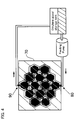
- FIG. 4 is a schematic view of a solar heat collector system utilizing a solar heat collector panel 70 in accordance with the invention.
- a heating medium such as an antifreeze solution or water
- the heating medium which flows into the heat collector panel through the pipe entrance 80 at low temperature, receives heat from the heat collection plates 40 as it flows through the pipes 50 within the panel 70.
- the temperature of the heating medium rises, and heating medium flows out through the exit 90 of the panel at an elevated temperature.
- the heat collection plates 40 which are coated with a film 30 of titanium oxynitride or aluminum oxynitride, and the pipes 50, are covered with transparent silica aerogel and have an integrated structure
- sunlight can be absorbed by the bottom as well as by the top of panel 70.
- the panel 70 is installed above a surface covered with snow, sunlight is incident on the top of the panel directly, and sunlight reflected back from the surface of the snow is incident on the bottom of the panel. Therefore, the solar heat collection efficiency is markedly increased in comparison with that of a conventional panel.
- ethylene glycol was circulated as a heating medium for one hour in the solar heat collector system using a panel 70 in accordance with the invention.
- the air temperature was 9.5 degrees Celsius
- the average quantity of the sunlight was 852 J/S .
- the measured temperature of the ethylene glycol at the exit 90 was 154 degrees Celsius.
- the solar heat collector panel of the invention in which a selective absorption film and silica aerogel are integrated, is superior in insulation performance to a conventional solar heat collector panel.
- Comparative example 2 since the heat collector panel was simply sandwiched between blocks of silica aerogel, it is believed that small gaps in the sides of the units, allowed convection of air and a loss of heat occurred. On the other hand, air convection cannot occur in heat collector panel according to the invention and the invention therefore exhibits superior insulation.
- the invention affords the maker of a solar heat collector panel a high degree of flexibility in the choice of shape and size of the panel, since the panel is made up of a number of small interconnected units.
- the solar heat collector panel can be formed not only in a planar configuration, but, by increasing the degree of freedom of the connectors, it can be formed alternatively with a curved surface so that it can be installed, and utilized more effectively, in various kinds of limited spaces.
- the invention allows a highly effective solar heat collector system to be fabricated in accordance with the consumer's heat capacity requirements.
- the heat collection plate is buried in a transparent heat insulating material, the strength of the transparent heat insulating material is improved. Therefore, the inventionmakes it more practical to utilize a heat insulation material such as a silica aerogel, having superior heat insulating properties and light weight, despite its low strength.
- the solar heat collector panel of the invention does not permit convection of air, and is highly superior in insulation performance.
- heavy insulation as in conventional heat collector panels is unnecessary, the weight of the panel is greatly reduced, the panel is structurally simplified, and it can be produced at low cost.
Landscapes
- Engineering & Computer Science (AREA)
- Chemical & Material Sciences (AREA)
- Sustainable Energy (AREA)
- Life Sciences & Earth Sciences (AREA)
- Physics & Mathematics (AREA)
- Sustainable Development (AREA)
- Thermal Sciences (AREA)
- Combustion & Propulsion (AREA)
- Mechanical Engineering (AREA)
- General Engineering & Computer Science (AREA)
- Dispersion Chemistry (AREA)
- Silicon Compounds (AREA)
- Photovoltaic Devices (AREA)
Abstract
A unit (10) of a solar heat collector panel has a structure in which a heat collection plate (40) and pipes (50) foraheating medium are unified with transparent heat insulating material (20). The heat collection plate (40) is coated with a selective absorption film (30) of MOxNy (where M is Ti or Al, x is the number of oxygen atoms, and y is the number of nitrogen atoms). The transparent heat insulating material (20) is silica aerogel. The heat collection plate (40) is buried in the transparent heat insulating material (20), improving the strength of the transparent heat insulating material (20). Therefore, a heat insulation material such as silica aerogel can be used as a heat insulation material in a solar heat collector panel. Since a selective absorption film (30), a heat collection plate (40) and a metal pipe (50) for a circulating heating medium are sealed without gaps, no convection of air occurs, heat insulation performance is superior, and the panel is lighter in weight and structurally simplified. The projection of the unit (10) is an equilateral polygon, and the shape and/or size of a solar heat collector panel (70) can be selected as desired by connecting the adjoining units (10) using connectors (60). It is possible to form the assembled panel with a three-dimensional or curved surface by using connectors (60) having appropriate shapes.
Description
- This invention relates to solar heat collectors, and particularly to improvements in flat solar heat collector panels.
- A rising concern about environmental problems and energy problems, has brought about an increased demand for solar heat collector panels.
- Among the known types of solar heat collector panels, the two main types are the flat panel type and the vacuum tube type. Because of its simple structure and relatively low cost, the flat panel solar heat collector is becoming the mainstream type of solar heat collector.
- In the flat panel collector, heat loss by convection and conduction is relatively high compared to the heat loss from a vacuum tube type collector. Consequently, high efficiency heat insulation is needed in the case of a flat panel collector. Double layers of glass were used for heat insulation in the light-collecting parts of conventional flat panel collectors. However, the double layers of glass were relatively heavy, and required a housing having a relatively high strength.
- Studies have been carried out with the objective of improving the heat collection efficiency of flat panel collectors, and the results of efforts to improve heat collection efficiency are disclosed in a number of references including, for example, Unexamined
Japanese Patent Publication No. 217961/1997 Japanese Patent Publication No. 2002-130835 - Silica aerogel, which has a high porosity and extremely low thermal conductivity, is known as a high efficiency insulation material. Silica aerogel has a relatively high visible ray transmission factor, and is light in weight, having a specific gravity of only about 0.1. Its applicability as a heat insulation material for a solar heat collector panel has been explored. However, since silica aerogel has relatively low mechanical strength, and requires a special handling when bonded using adhesives, so far, it has found only limited use as a heat insulation material for solar heat collector panels. By way of example, unexamined
Japanese Patent Publication No. 217961/1997 - Conventional solar heat collector panels, as shown for example in unexamined
Japanese Patent Publication No. 217961/1997 Japanese Patent Publication 2002/130835 - In the case of the heat collector described in unexamined
Japanese Patent Publication No. 217961/1997 - In view of the above-mentioned problems, among the objects of the invention are the provision of a flat panel solar heat collector, the shape and size of which can be changed with a high degree of flexibility in order to meet the demands of consumers, the provision of a solar heat collector panel which has improved heat insulation performance and heat collection efficiency, and also the simplification of the structure of the flat panel.
- The invention has solved the above-mentioned problems by a solar heat collector panel characterized in that it comprises pipes and connectors, and in which the shape and/or size of the panel can be changed as desired by connecting adjoining units through the connector.
- In addition, the invention provides a solar heat collector panel characterized by a structure in which a heat collection plate and a pipe for a heating medium are integrally formed with a transparent heat insulating material.
- It is preferable that the heat collection plate is coated with a selective absorption film of MOxNy (where M is Ti (titanium) or A1 (aluminum)) and said transparent heat insulating material is silica aerogel.
- It is preferable that the transparent heat insulating material be a silica aerogel made of wet silica gel obtained by supercritical drying, and it is also preferable that the pipe for the heating medium be joined with the heat collection plate.
-
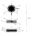
- FIG. 1 (a) is a top view of a unit of a solar heat collector panel according to the invention;
- FIG. 1 (b) is a schematic view of the unit of FIG. 1(a), as viewed in the direction of
arrow 1 in FIG. 1(a); - FIG. 1 (c) is a schematic view of the unit of FIG. 1(a) as viewed in the direction of
arrow 2 in FIG. 1(a); - FIG. 2 is a two-part schematic view showing two steps of a process for joining a silica aerogel with a selective absorption film;
- FIG. 3 is a schematic illustration of a solar heat collector panel that is assembled by coupling multiple solar heat collector units in accordance with the invention; and
- FIG. 4 is a schematic illustration of a solar heat collector system utilizing a solar heat collector panel according to the invention.
- Referring to FIGs. 1 (a) - 1 (c), the solar heat collector unit 10 (hereinafter referred to as a "unit") comprises
silica aerogel 20 as a transparent heat insulating material, aheat collection plate 40, the surface of which is coated with aselective absorption film 30,metal pipes 50 for circulating heating medium (hereinafter simply called the "pipes") andconnectors 60. - In one preferred embodiment, the
unit 10, in plan view as in FIG. 1 (a), is in the shape of an equilateral hexagon having sides each about 40mm in length, and a depth of about 20mm. However, the shape of the unit, that is, the projection of the unit on a plane parallel to its light-receiving surface, is not limited to an equilateral hexagon, and the unit can be made in any of a wide variety of other shapes, including, but not limited to, other equilateral polygons or rectangles. - As shown in FIGs. 1(a) and 1(c), a
pipe 50 protrudes from thesilica aerogel 20, and aconnector 60 is arranged at each end thereof. - One or more connectors are provided in each
unit 10, and a solar heat collector panel can be formed by connecting theconnectors 60 ofadjoining units 10. - As shown in FIG. 1 (b), a
pipe 50 is coupled with the lower part of aheat collection plate 40, and each surface of theplate 40 is coated with aselective absorption film 30. Theselective absorption films 30, theheat collection plate 40, andpipes 50 are wholly covered withsilica aerogel 20, so that each unit is an integral body. - In accordance with the invention, the
selective absorption film 30, which coats theheat collection plate 40, is made of a thin film of titanium oxynitride or aluminum oxynitride. Titanium oxynitride and aluminum oxynitride are preferred as materials for the selective absorption film because they absorb the wavelengths of sunlight but do not emit infrared wavelengths. Any of a wide variety of metals can be used as the material of theheat collectionplate 40 and thepipes 50. Copper, however, is preferred as the material of thecollection plate 40 and thepipes 50, because of its high thermal conductivity. - As mentioned above, silica aerogel is known as a high efficiency heat insulation material. In the invention, silica aerogel is preferred as a heat insulation material because it has a high porosity and an extremely low thermal conductivity, and because it exhibits a high visible ray transmission, and is very light in weight, having a specific gravity around 0.1.
- The
silica aerogel 20 used in the invention is produced by supercritical drying of a wet gel made from alkoxysilanes by hydrolysis and polycondensation. - Silica aerogel produced by supercritical drying has no liquid-vapor interface, does not develop capillary action, and exhibits only minimal contraction. It is preferable as a heat insulation material of a solar heat collector panel because of its transparency.
- A preferred adhesion process for integrating a
silica aerogel 20 with theheat collection plate 40 andpipes 50, which have been coated with aselective absorption film 30, will now be described. - First, a sol for producing wet gel is prepared. Any of various kinds of alkoxysilane can be used as a raw material for the wet gel. An example of a suitable alkoxysilane for use in the invention, is MS51 (methyl silicate 51). Ammonium hydroxide is added as a catalyst to methyl silicate 51 diluted with methanol, to produce the sol.
- A
heat collection plate 40 andpipes 50, which were coated with aselective absorption film 30 of titanium oxynitride or aluminum oxynitride were placed on the support member of a mold as illustrated bystep 1 of FIG. 2. Then, the sol was poured to the depth of about 2cm in the mold as illustrated bystep 2 of FIG. 2. Hydrolysis of the sol and polycondensation progressed, and the sol became awet gel 62. - After aging for about one day, the wet gel became unified with the
heat collection plate 40 andpipes 50. The wet gel was then detached from the mold. - Supercritical drying of the wet gel provided by the above-mentioned process was carried out.
- Supercritical drying is known technology, and is disclosed in a number of references, including, but not limited to unexamined
Japanese Patent Publication 2001-139321 U.S. Patent No. 4,402,927 . Therefore, detailed description of the supercritical drying process is unnecessary, and a more general procedure will be described. - First, after filling an autoclave with a supercritical medium (alcohol system), the wet gel, which had undergone a liquidphase substitution for two days, was put into the autoclave, and a non-active gas was pumped into the autoclave.
- Next, the autoclave containing the wet gel was heated. Pressure was increased by heating the alcohol rather than by means of a booster pump. A pressure regulating valve was set to operate in the vicinity of 80 kgf/cm2 to prevent the pressure from becoming excessive. The temperature rose from 0 to 200 degrees Celsius in four hours (at an average rate of approximately 50 degrees Celsius/h), and from 200 to 300 degrees Celsius in another four hours (at an average rate of 25 degrees Celsius/h). Afterwards, a temperature of about 300 degrees Celsius was maintained for two or three hours. In addition, beginning at the time at which the temperature reached 300 degrees Celsius, and during the time at which the temperature was maintained at 300 degrees Celsius (for two or three hours), the pressure was lowered to atmospheric pressure at the rate of about 0.5kgf/cm2/min.
- After releasing alcohol from the autoclave, non-active gas was introduced, and the temperature was lowered slowly to remove alcohol (as gas) from the autoclave and the piping system. After confirming the temperature drop, the silica aerogel was taken out of the autoclave.
- It should be noted that the supercritical fluid for preparing silica aerogel is not limited to alcohol. Other supercritical media such as carbon dioxide can also be used.
- The above process results in the
heat collection plate 40 and thepipe 50, coated with aselective absorption film 30, being wholly covered withsilica aerogel 20, and sealed wi thout a gap. Thus theuni t 10, produced by the above-described process does not permit convection of air, and it exhibits highly superior insulation performance. - Although silica aerogel is an extremely weak material, in the invention, the silica aerogel is reinforced the
heat collection plate 40 buried inside it. Furthermore, adequate strength to meet the requirements of practical use, can be achieved by covering the silica aerogel with a polymer, glass, or other suitable material. - A solar
heat collector panel 70, having the arbitrary configuration illustrated in FIG. 3, is formed by assembling a plurality of equilateral hexagonalheat collection units 10 and connecting the ends of their pipes. The shape of the solarheat collector panel 70 in FIG. 3 is just one example of an almost unlimited variety of possible panel shapes and sizes that can be produced by appropriate arrangement and interconnection ofheat collection units 10 in adjoining relationship. Thus a solar heat collector panel corresponding to the heat capacity required by a consumer can be produced by choosing an appropriate number of collection units, and can be shaped to accommodate the available space. - Moreover, the solar heat collector panels of the invention are not limited to planar panels. It is possible to form the panel so that it has a curved surface by providing the collection units, and the connectors in appropriate shapes. Therefore, when the available space for installation of a collector panel is limited to a small area or an uneven surface, more effective utilization of the limited space can be achieved by combining the units to form a three-dimensional panel.
- FIG. 4 is a schematic view of a solar heat collector system utilizing a solar
heat collector panel 70 in accordance with the invention. A heating medium, such as an antifreeze solution or water, is circulated within the system by a feeding pump. The heating medium, which flows into the heat collector panel through thepipe entrance 80 at low temperature, receives heat from theheat collection plates 40 as it flows through thepipes 50 within thepanel 70. Thus, the temperature of the heating medium rises, and heating medium flows out through theexit 90 of the panel at an elevated temperature. - Since the
heat collection plates 40, which are coated with afilm 30 of titanium oxynitride or aluminum oxynitride, and thepipes 50, are covered with transparent silica aerogel and have an integrated structure, sunlight can be absorbed by the bottom as well as by the top ofpanel 70. For example, when thepanel 70 is installed above a surface covered with snow, sunlight is incident on the top of the panel directly, and sunlight reflected back from the surface of the snow is incident on the bottom of the panel. Therefore, the solar heat collection efficiency is markedly increased in comparison with that of a conventional panel. - A concrete example of the invention will be explained below and compared with two comparative examples. It should be understood that the invention is not limited to this concrete example.
- In the concrete example of the invention, ethylene glycol was circulated as a heating medium for one hour in the solar heat collector system using a
panel 70 in accordance with the invention. The air temperature was 9.5 degrees Celsius , and the average quantity of the sunlight was 852 J/S . The measured temperature of the ethylene glycol at theexit 90, was 154 degrees Celsius. - On the other hand, when ethylene glycol was circulated, under the same conditions as in the above example, through a conventional solar heat collector panel which was simply sandwiched between blocks of silica aerogel, the measured temperature of the ethylene glycol at the exit was only 90 degrees Celsius.
- In another comparative example, in which a conventional solar heat collector panel having an aluminum case containing foamed polyurethane and a selective absorption film, and having a double glass structure, when ethylene glycol was circulated in the same condition as the concrete example, the temperature of the ethylene glycol at the exit was only 70 degrees Celsius.
- From the performance of the examples, it has become apparent that the solar heat collector panel of the invention, in which a selective absorption film and silica aerogel are integrated, is superior in insulation performance to a conventional solar heat collector panel. In Comparative example 2, since the heat collector panel was simply sandwiched between blocks of silica aerogel, it is believed that small gaps in the sides of the units, allowed convection of air and a loss of heat occurred. On the other hand, air convection cannot occur in heat collector panel according to the invention and the invention therefore exhibits superior insulation.
- The invention affords the maker of a solar heat collector panel a high degree of flexibility in the choice of shape and size of the panel, since the panel is made up of a number of small interconnected units. The solar heat collector panel can be formed not only in a planar configuration, but, by increasing the degree of freedom of the connectors, it can be formed alternatively with a curved surface so that it can be installed, and utilized more effectively, in various kinds of limited spaces.
- Also, the invention allows a highly effective solar heat collector system to be fabricated in accordance with the consumer's heat capacity requirements.
- Further, since the heat collection plate is buried in a transparent heat insulating material, the strength of the transparent heat insulating material is improved. Therefore, the inventionmakes it more practical to utilize a heat insulation material such as a silica aerogel, having superior heat insulating properties and light weight, despite its low strength.
- Since the selective absorption film, the heat collection plate and the metal heating medium circulation pipe are sealed within a transparent heat insulating material without gaps, the solar heat collector panel of the invention does not permit convection of air, and is highly superior in insulation performance. With the invention, heavy insulation as in conventional heat collector panels is unnecessary, the weight of the panel is greatly reduced, the panel is structurally simplified, and it can be produced at low cost.
Claims (8)
- A solar heat collector unit characterized in that said solar heat collector unit comprises a pipe and a connector, whereby solar heat collectors of various desired shapes and/or sizes can be assembled by interconnecting multiple units using the connector.
- A solar heat collector unit according to claim 1, wherein the shape of projection of said solar heat collector unit is an equilateral polygon.
- A solar heat collector unit according to claim 1 or 2, wherein said solar heat collector unit comprises two or more connectors.
- A solar heat collector unit according to any one of claims 1 to 3, wherein said solar heat collector unit uses a thin film of titanium oxynitride or aluminum oxynitride as a selective absorption film, and silica aerogel as a transparent heat insulation material.
- A solar heat collector panel characterized in the structure in which a heat collection plate and a pipe for heating medium are integrally formed with a transparent heat insulating material.
- A solar heat collector panel according to claim 5, wherein said heat collection plate is coated with a selective absorption film of MOxNy (where M is Ti or Al) and said transparent heat insulating material is silica aerogel.
- A solar heat collector panel according to claim 5 or 6, wherein said transparent heat insulating material is silica aerogel which is made of silica wet gel obtained by super critical drying.
- A solar heat collector panel according to any one of claim 5 to 7, wherein said pipe for heating medium is joined with said heat collection plate.
Applications Claiming Priority (2)
| Application Number | Priority Date | Filing Date | Title |
|---|---|---|---|
| JP2003403997A JP2005164132A (en) | 2003-12-03 | 2003-12-03 | Solar heat collector panel |
| PCT/JP2004/018452 WO2005068918A1 (en) | 2003-12-03 | 2004-12-03 | Solar heat collector panel |
Publications (1)
| Publication Number | Publication Date |
|---|---|
| EP1707897A1 true EP1707897A1 (en) | 2006-10-04 |
Family
ID=34727094
Family Applications (1)
| Application Number | Title | Priority Date | Filing Date |
|---|---|---|---|
| EP04821111A Withdrawn EP1707897A1 (en) | 2003-12-03 | 2004-12-03 | Solar heat collector panel |
Country Status (5)
| Country | Link |
|---|---|
| EP (1) | EP1707897A1 (en) |
| JP (1) | JP2005164132A (en) |
| KR (1) | KR20060109917A (en) |
| CN (1) | CN1890511A (en) |
| WO (1) | WO2005068918A1 (en) |
Cited By (11)
| Publication number | Priority date | Publication date | Assignee | Title |
|---|---|---|---|---|
| EP2000748A2 (en) | 2007-06-06 | 2008-12-10 | Herr Orhan Ustun | Collector element to generate heat from sun radiation and protective cover therefor |
| WO2010080060A1 (en) * | 2009-01-08 | 2010-07-15 | Ab Airglass | Silica aerogel as transparent panel in energy saving window |
| WO2010080059A1 (en) * | 2009-01-08 | 2010-07-15 | Ab Airglass | Silica aerogel body as isolation in a solar collector system |
| WO2010028818A3 (en) * | 2008-09-09 | 2011-01-13 | Sola-Term Gmbh | Solar flat collector |
| ITPD20090316A1 (en) * | 2009-10-28 | 2011-04-29 | Everlux S R L | MULTI-PIPE FOR HYDRAULIC CONNECTION AND SOLAR PANEL WIRING. |
| ITBG20090069A1 (en) * | 2009-12-30 | 2011-06-30 | Alessandro Sala | SOLAR PIPE |
| DE102010008059A1 (en) * | 2010-02-16 | 2011-08-18 | Albrecht 65618 Kretzschmar | High temperature heat accumulator system for e.g. propulsion of automobile, has transducer unit converting heat energy into different forms of energy or amounts of power based on application, where system is supplemented to control target |
| ES2399921A1 (en) * | 2011-04-19 | 2013-04-04 | Romarket, S.L. | Solar accumulator. (Machine-translation by Google Translate, not legally binding) |
| WO2014053633A1 (en) * | 2012-10-05 | 2014-04-10 | Maike Brabenec | Photovoltaic-thermal hybrid solar system |
| CN104482671A (en) * | 2014-12-10 | 2015-04-01 | 山东力诺瑞特新能源有限公司 | Novel ultra-thin and light flat-plate heat collector of heat absorbing body |
| WO2016151341A3 (en) * | 2015-03-26 | 2016-11-17 | Solar Fluidics Pte Ltd | Solar energy system |
Families Citing this family (7)
| Publication number | Priority date | Publication date | Assignee | Title |
|---|---|---|---|---|
| JP2008309456A (en) * | 2007-06-18 | 2008-12-25 | Daiwa House Ind Co Ltd | Solar system |
| CN101793438A (en) * | 2010-02-26 | 2010-08-04 | 东莞市创一新材料科技有限公司 | Composite flat plate type solar heat collecting plate and preparation thereof |
| CN102679599A (en) * | 2012-06-05 | 2012-09-19 | 卢斌 | Flat plate solar collector core |
| CN103075828A (en) * | 2013-01-31 | 2013-05-01 | 卢孟磊 | Silicon dioxide (SiO2) aerogel trough-type solar heat-collecting tube and preparation method thereof |
| CN103216954A (en) * | 2013-04-26 | 2013-07-24 | 江苏七政新能源有限公司 | Wrapped solar water heater |
| CN104315728A (en) * | 2014-11-25 | 2015-01-28 | 山东力诺瑞特新能源有限公司 | Flat plate collector made of novel thermal insulation material |
| CN114165929B (en) * | 2022-01-10 | 2024-04-19 | 兰州交通大学 | Flat-plate type solar heat collector heat absorber with integrated light-transmitting heat-insulating layer and preparation method thereof |
Family Cites Families (8)
| Publication number | Priority date | Publication date | Assignee | Title |
|---|---|---|---|---|
| JPS5350538A (en) * | 1976-10-19 | 1978-05-09 | Matsushita Electric Works Ltd | Collector |
| JPS57100252A (en) * | 1980-12-12 | 1982-06-22 | Kubota Ltd | Building material |
| JPS58192001A (en) * | 1982-05-06 | 1983-11-09 | Takashi Mori | Solar light condensing device |
| JPS59215546A (en) * | 1982-10-29 | 1984-12-05 | Sharp Corp | Solar heat collector |
| JPS59161460U (en) * | 1983-04-15 | 1984-10-29 | シャープ株式会社 | Light/thermal combined collector |
| JPH11103087A (en) * | 1997-09-26 | 1999-04-13 | Sekisui Chem Co Ltd | Light-heat hybrid panel |
| JP2001174071A (en) * | 1999-07-23 | 2001-06-29 | Sekisui Chem Co Ltd | Method of manufacturing photothermal hybrid panel and photothermal hybrid panel |
| AUPR356601A0 (en) * | 2001-03-07 | 2001-04-05 | University Of Sydney, The | Solar energy reflector array |
-
2003
- 2003-12-03 JP JP2003403997A patent/JP2005164132A/en active Pending
-
2004
- 2004-12-03 EP EP04821111A patent/EP1707897A1/en not_active Withdrawn
- 2004-12-03 WO PCT/JP2004/018452 patent/WO2005068918A1/en not_active Ceased
- 2004-12-03 KR KR1020067009897A patent/KR20060109917A/en not_active Withdrawn
- 2004-12-03 CN CNA2004800359748A patent/CN1890511A/en active Pending
Non-Patent Citations (1)
| Title |
|---|
| See references of WO2005068918A1 * |
Cited By (16)
| Publication number | Priority date | Publication date | Assignee | Title |
|---|---|---|---|---|
| EP2000748A2 (en) | 2007-06-06 | 2008-12-10 | Herr Orhan Ustun | Collector element to generate heat from sun radiation and protective cover therefor |
| WO2010028818A3 (en) * | 2008-09-09 | 2011-01-13 | Sola-Term Gmbh | Solar flat collector |
| WO2010080060A1 (en) * | 2009-01-08 | 2010-07-15 | Ab Airglass | Silica aerogel as transparent panel in energy saving window |
| WO2010080059A1 (en) * | 2009-01-08 | 2010-07-15 | Ab Airglass | Silica aerogel body as isolation in a solar collector system |
| ITPD20090316A1 (en) * | 2009-10-28 | 2011-04-29 | Everlux S R L | MULTI-PIPE FOR HYDRAULIC CONNECTION AND SOLAR PANEL WIRING. |
| WO2011051262A1 (en) * | 2009-10-28 | 2011-05-05 | Everlux S.R.L. | Multilayer tube for hydraulic connection and wiring of solar panels |
| CN102656396A (en) * | 2009-10-28 | 2012-09-05 | 艾瓦拉克丝责任有限公司 | Multilayer tube for hydraulic connection and wiring of solar panels |
| EA021278B1 (en) * | 2009-12-30 | 2015-05-29 | Актарус Груп С.Р.Л. | Solar panel tube |
| ITBG20090069A1 (en) * | 2009-12-30 | 2011-06-30 | Alessandro Sala | SOLAR PIPE |
| WO2011080563A1 (en) * | 2009-12-30 | 2011-07-07 | Paolo Spinelli | Solar panel tube |
| CN102713393A (en) * | 2009-12-30 | 2012-10-03 | 阿克塔鲁斯集团有限责任公司 | Solar panel tube |
| DE102010008059A1 (en) * | 2010-02-16 | 2011-08-18 | Albrecht 65618 Kretzschmar | High temperature heat accumulator system for e.g. propulsion of automobile, has transducer unit converting heat energy into different forms of energy or amounts of power based on application, where system is supplemented to control target |
| ES2399921A1 (en) * | 2011-04-19 | 2013-04-04 | Romarket, S.L. | Solar accumulator. (Machine-translation by Google Translate, not legally binding) |
| WO2014053633A1 (en) * | 2012-10-05 | 2014-04-10 | Maike Brabenec | Photovoltaic-thermal hybrid solar system |
| CN104482671A (en) * | 2014-12-10 | 2015-04-01 | 山东力诺瑞特新能源有限公司 | Novel ultra-thin and light flat-plate heat collector of heat absorbing body |
| WO2016151341A3 (en) * | 2015-03-26 | 2016-11-17 | Solar Fluidics Pte Ltd | Solar energy system |
Also Published As
| Publication number | Publication date |
|---|---|
| KR20060109917A (en) | 2006-10-23 |
| WO2005068918A1 (en) | 2005-07-28 |
| CN1890511A (en) | 2007-01-03 |
| JP2005164132A (en) | 2005-06-23 |
Similar Documents
| Publication | Publication Date | Title |
|---|---|---|
| EP1707897A1 (en) | Solar heat collector panel | |
| US4169460A (en) | Solar converter system with thermal overload protection | |
| US5941238A (en) | Heat storage vessels for use with heat pumps and solar panels | |
| US3866285A (en) | Method of constructing a solar energy collector | |
| US4392008A (en) | Combined electrical and thermal solar collector | |
| US4120285A (en) | Modular tubular solar energy collector apparatus | |
| CN103492815B (en) | Solar thermal collector | |
| US20190056147A1 (en) | Thin multi-channel heat exchanger | |
| WO2008100947A2 (en) | Solar energy apparatus | |
| KR20120002258U (en) | High temperature graphite heat exchanger | |
| JP2013508661A (en) | Solar collector | |
| KR20170141185A (en) | Hybrid solar cell module | |
| US20120125582A1 (en) | Heat exchanger of the plate type | |
| US20150292770A1 (en) | Solar thermal collector system and method for pitched roof constructions | |
| CN204507741U (en) | The attemperator of salt storage tank | |
| US20100126500A1 (en) | Heat collector | |
| CN105408695A (en) | Energy storage system | |
| US20100108054A1 (en) | Optically efficient and thermally protected solar heating apparatus and method | |
| JPH09217961A (en) | Solar heat collector | |
| CN109972490B (en) | Box girder self-controlling temperature drape with phase change endothermic and radiation cooling functions | |
| JP2011222824A (en) | Waste heat recovery method with solar cell module and waste heat recovery apparatus therewith | |
| SE533058C2 (en) | Silica aerogel body as insulation in a solar collector system | |
| WO2019032698A1 (en) | Energy collector | |
| CN211509016U (en) | High-efficiency solar power generation heat collection and radiation refrigeration paraboloid type device | |
| GB2089024A (en) | Solar energy collector |
Legal Events
| Date | Code | Title | Description |
|---|---|---|---|
| PUAI | Public reference made under article 153(3) epc to a published international application that has entered the european phase |
Free format text: ORIGINAL CODE: 0009012 |
|
| 17P | Request for examination filed |
Effective date: 20060628 |
|
| AK | Designated contracting states |
Kind code of ref document: A1 Designated state(s): AT BE BG CH CY CZ DE DK EE ES FI FR GB GR HU IE IS IT LI LT LU MC NL PL PT RO SE SI SK TR |
|
| AX | Request for extension of the european patent |
Extension state: AL BA HR LV MK YU |
|
| STAA | Information on the status of an ep patent application or granted ep patent |
Free format text: STATUS: THE APPLICATION HAS BEEN WITHDRAWN |
|
| 18W | Application withdrawn |
Effective date: 20071102 |