EP1707870A1 - Abri d'attente pour voyageurs avec dispositif de commande de l'éclairage - Google Patents
Abri d'attente pour voyageurs avec dispositif de commande de l'éclairage Download PDFInfo
- Publication number
- EP1707870A1 EP1707870A1 EP05077658A EP05077658A EP1707870A1 EP 1707870 A1 EP1707870 A1 EP 1707870A1 EP 05077658 A EP05077658 A EP 05077658A EP 05077658 A EP05077658 A EP 05077658A EP 1707870 A1 EP1707870 A1 EP 1707870A1
- Authority
- EP
- European Patent Office
- Prior art keywords
- shelter
- control device
- light
- shelter according
- detector
- Prior art date
- Legal status (The legal status is an assumption and is not a legal conclusion. Google has not performed a legal analysis and makes no representation as to the accuracy of the status listed.)
- Granted
Links
- 238000001514 detection method Methods 0.000 claims abstract description 5
- 238000005286 illumination Methods 0.000 claims description 3
- SEQDDYPDSLOBDC-UHFFFAOYSA-N Temazepam Chemical compound N=1C(O)C(=O)N(C)C2=CC=C(Cl)C=C2C=1C1=CC=CC=C1 SEQDDYPDSLOBDC-UHFFFAOYSA-N 0.000 description 5
- 238000010586 diagram Methods 0.000 description 1
- 238000005265 energy consumption Methods 0.000 description 1
- 230000001771 impaired effect Effects 0.000 description 1
- 229910052754 neon Inorganic materials 0.000 description 1
- GKAOGPIIYCISHV-UHFFFAOYSA-N neon atom Chemical compound [Ne] GKAOGPIIYCISHV-UHFFFAOYSA-N 0.000 description 1
- 230000035945 sensitivity Effects 0.000 description 1
- 239000002689 soil Substances 0.000 description 1
Images

Classifications
-
- F—MECHANICAL ENGINEERING; LIGHTING; HEATING; WEAPONS; BLASTING
- F21—LIGHTING
- F21V—FUNCTIONAL FEATURES OR DETAILS OF LIGHTING DEVICES OR SYSTEMS THEREOF; STRUCTURAL COMBINATIONS OF LIGHTING DEVICES WITH OTHER ARTICLES, NOT OTHERWISE PROVIDED FOR
- F21V23/00—Arrangement of electric circuit elements in or on lighting devices
- F21V23/04—Arrangement of electric circuit elements in or on lighting devices the elements being switches
- F21V23/0442—Arrangement of electric circuit elements in or on lighting devices the elements being switches activated by means of a sensor, e.g. motion or photodetectors
- F21V23/0471—Arrangement of electric circuit elements in or on lighting devices the elements being switches activated by means of a sensor, e.g. motion or photodetectors the sensor detecting the proximity, the presence or the movement of an object or a person
-
- E—FIXED CONSTRUCTIONS
- E04—BUILDING
- E04H—BUILDINGS OR LIKE STRUCTURES FOR PARTICULAR PURPOSES; SWIMMING OR SPLASH BATHS OR POOLS; MASTS; FENCING; TENTS OR CANOPIES, IN GENERAL
- E04H1/00—Buildings or groups of buildings for dwelling or office purposes; General layout, e.g. modular co-ordination or staggered storeys
- E04H1/12—Small buildings or other erections for limited occupation, erected in the open air or arranged in buildings, e.g. kiosks, waiting shelters for bus stops or for filling stations, roofs for railway platforms, watchmen's huts or dressing cubicles
- E04H1/1205—Small buildings erected in the open air
- E04H1/1211—Waiting shelters for bus stops
-
- H—ELECTRICITY
- H05—ELECTRIC TECHNIQUES NOT OTHERWISE PROVIDED FOR
- H05B—ELECTRIC HEATING; ELECTRIC LIGHT SOURCES NOT OTHERWISE PROVIDED FOR; CIRCUIT ARRANGEMENTS FOR ELECTRIC LIGHT SOURCES, IN GENERAL
- H05B47/00—Circuit arrangements for operating light sources in general, i.e. where the type of light source is not relevant
- H05B47/10—Controlling the light source
- H05B47/105—Controlling the light source in response to determined parameters
- H05B47/115—Controlling the light source in response to determined parameters by determining the presence or movement of objects or living beings
-
- F—MECHANICAL ENGINEERING; LIGHTING; HEATING; WEAPONS; BLASTING
- F21—LIGHTING
- F21S—NON-PORTABLE LIGHTING DEVICES; SYSTEMS THEREOF; VEHICLE LIGHTING DEVICES SPECIALLY ADAPTED FOR VEHICLE EXTERIORS
- F21S9/00—Lighting devices with a built-in power supply; Systems employing lighting devices with a built-in power supply
- F21S9/02—Lighting devices with a built-in power supply; Systems employing lighting devices with a built-in power supply the power supply being a battery or accumulator
- F21S9/03—Lighting devices with a built-in power supply; Systems employing lighting devices with a built-in power supply the power supply being a battery or accumulator rechargeable by exposure to light
-
- F—MECHANICAL ENGINEERING; LIGHTING; HEATING; WEAPONS; BLASTING
- F21—LIGHTING
- F21V—FUNCTIONAL FEATURES OR DETAILS OF LIGHTING DEVICES OR SYSTEMS THEREOF; STRUCTURAL COMBINATIONS OF LIGHTING DEVICES WITH OTHER ARTICLES, NOT OTHERWISE PROVIDED FOR
- F21V23/00—Arrangement of electric circuit elements in or on lighting devices
- F21V23/04—Arrangement of electric circuit elements in or on lighting devices the elements being switches
- F21V23/0442—Arrangement of electric circuit elements in or on lighting devices the elements being switches activated by means of a sensor, e.g. motion or photodetectors
-
- Y—GENERAL TAGGING OF NEW TECHNOLOGICAL DEVELOPMENTS; GENERAL TAGGING OF CROSS-SECTIONAL TECHNOLOGIES SPANNING OVER SEVERAL SECTIONS OF THE IPC; TECHNICAL SUBJECTS COVERED BY FORMER USPC CROSS-REFERENCE ART COLLECTIONS [XRACs] AND DIGESTS
- Y02—TECHNOLOGIES OR APPLICATIONS FOR MITIGATION OR ADAPTATION AGAINST CLIMATE CHANGE
- Y02B—CLIMATE CHANGE MITIGATION TECHNOLOGIES RELATED TO BUILDINGS, e.g. HOUSING, HOUSE APPLIANCES OR RELATED END-USER APPLICATIONS
- Y02B10/00—Integration of renewable energy sources in buildings
- Y02B10/10—Photovoltaic [PV]
-
- Y—GENERAL TAGGING OF NEW TECHNOLOGICAL DEVELOPMENTS; GENERAL TAGGING OF CROSS-SECTIONAL TECHNOLOGIES SPANNING OVER SEVERAL SECTIONS OF THE IPC; TECHNICAL SUBJECTS COVERED BY FORMER USPC CROSS-REFERENCE ART COLLECTIONS [XRACs] AND DIGESTS
- Y02—TECHNOLOGIES OR APPLICATIONS FOR MITIGATION OR ADAPTATION AGAINST CLIMATE CHANGE
- Y02B—CLIMATE CHANGE MITIGATION TECHNOLOGIES RELATED TO BUILDINGS, e.g. HOUSING, HOUSE APPLIANCES OR RELATED END-USER APPLICATIONS
- Y02B20/00—Energy efficient lighting technologies, e.g. halogen lamps or gas discharge lamps
- Y02B20/40—Control techniques providing energy savings, e.g. smart controller or presence detection
Definitions
- the present invention relates to passenger shelters, of the type referred to as "bus shelter” ®.
- the invention relates to a shelter waiting for passengers comprising a roof under which is disposed a plurality of electrical light spots controlled by a control device.
- the present invention is intended to overcome these disadvantages.
- the energy consumption of the shelter's lighting can be greatly reduced, in particular by making it possible to establish a low-light standby mode, or even without lighting, as long as no traveler is detected. .
- the lower face 10 of the roof 2 comprises a plurality of juxtaposed modular plates 11 which in the example considered here are hexagonal in shape and may each have a surface of the order of 0.25 m 2 .
- each of the modular plates 11 may include a lighting point 12 adapted to illuminate downward, preferably with directional lighting.
- the lighting points 12 may be formed for example by light-emitting diodes of white color, or other.
- each of the modular plates 11 may comprise a presence detector 13, for example an infrared motion detector, which is oriented downwards and which is preferably itself sufficiently directional, so as to detect a present traveler V under cover 1, only if this traveler is in correspondence with the detector in question.
- a presence detector 13 for example an infrared motion detector, which is oriented downwards and which is preferably itself sufficiently directional, so as to detect a present traveler V under cover 1, only if this traveler is in correspondence with the detector in question.
- the detectors 13 may be adapted to detect a presence from a minimum height above the ground, this minimum height being for example between 30 cm and 120 cm: thus the detectors 13 can detect the presence of a child or of an adult, but do not detect the presence of an animal such as a relatively small dog or a cat. This minimum detection height can be obtained for example by calibrating the sensitivity of the detectors 13.
- all the electrical devices of the shelter 1 can be electrically powered by a photovoltaic power supply device 15 placed on the roof 2 of the shelter and associated with a battery 15a (FIG. 4).
- the battery 15a can supply the lighting device 8 of the panel 6, a control device 16 such as an electronic central processing unit (CPU) and a power supply circuit 17 which is controlled by the central unit 16 for controlling the operation of the light points 12 (L) and the level of electrical power delivered to each light point 12.
- a control device 16 such as an electronic central processing unit (CPU) and a power supply circuit 17 which is controlled by the central unit 16 for controlling the operation of the light points 12 (L) and the level of electrical power delivered to each light point 12.
Landscapes
- Engineering & Computer Science (AREA)
- Architecture (AREA)
- General Engineering & Computer Science (AREA)
- Civil Engineering (AREA)
- Structural Engineering (AREA)
- Circuit Arrangement For Electric Light Sources In General (AREA)
- Arrangement Of Elements, Cooling, Sealing, Or The Like Of Lighting Devices (AREA)
- Non-Portable Lighting Devices Or Systems Thereof (AREA)
Abstract
Description
- La présente invention est relative aux abris d'attente pour voyageurs, du type de ceux dénommés "Abribus"®.
- Plus particulièrement, l'invention concerne un abri d'attente pour voyageurs comprenant un toit sous lequel est disposée une pluralité de points lumineux électriques commandés par un dispositif de commande.
- Le document
US-A-5 107 637 décrit un exemple d'un tel abri. - Dans les abris connus de ce type, l'éclairage est soit éteint, soit allumé à puissance maximale en fonction de l'heure. Il en résulte une consommation électrique relativement importante qui est inutile une grande partie du temps, lorsque l'abri ne reçoit aucun voyageur.
- La présente invention a notamment pour but de pallier ces inconvénients.
- A cet effet, selon l'invention, un abri du genre en question est caractérisé en ce qu'il comporte une pluralité de détecteurs de présence adaptés pour détecter un voyageur sous l'abri, le dispositif de commande étant relié aux détecteurs et étant adapté pour sélectivement commander au moins certains desdits points lumineux en fonction de la détection ou non d'un voyageur par les détecteurs en correspondance avec lesdits points lumineux.
- Grâce à ces dispositions, on peut limiter fortement la consommation d'énergie de l'éclairage de l'abri, notamment en permettant d'établir un régime de veille à faible éclairage, voire sans éclairage, tant qu'aucun voyageur n'est détecté.
- Dans divers modes de réalisation de l'abri selon l'invention, on peut éventuellement avoir recours en outre à l'une et/ou à l'autre des dispositions suivantes :
- chaque détecteur est associé à au moins un point lumineux et le dispositif de commande est adapté pour allumer ledit point lumineux, en période nocturne, lorsque ledit détecteur détecte un voyageur ;
- chaque détecteur est associé à un point lumineux unique ;
- chaque détecteur est disposé sous le toit de l'abri au voisinage dudit au moins un point lumineux auquel il est associé ;
- le toit de l'abri présente une face inférieure comprenant une pluralité de plaques modulaires juxtaposées qui comportent chacune un point lumineux et un détecteur ;
- le dispositif de commande est adapté pour, lorsqu'un détecteur détecte un voyageur sous l'abri, allumer uniquement le ou les points lumineux disposés en correspondance avec le voyageur, en période nocturne ;
- le dispositif de commande est adapté pour faire fonctionner les points lumineux selon un mode de veille à faible consommation lorsque aucun détecteur ne détecte de voyageur sous l'abri, en période nocturne ;
- le dispositif de commande est adapté pour éteindre tous les points lumineux en mode de veille ;
- le dispositif de commande est adapté pour allumer au moins certains points lumineux à basse puissance en mode de veille ;
- le dispositif de commande est adapté pour allumer uniquement certains points lumineux en mode de veille ;
- le dispositif de commande est adapté pour allumer tour à tour au moins certains des points lumineux en mode de veille ;
- les détecteurs sont adaptés pour détecter une présence sous l'abri à partir d'une hauteur minimale comprise entre 30 et 120 cm au dessus du sol ;
- l'abri comporte un panneau d'affichage éclairé et le dispositif de commande est adapté pour faire fonctionner les points lumineux voisins du panneau d'affichage avec une puissance inférieure aux autres points lumineux ;
- le dispositif de commande est adapté pour détecter des dispositifs d'identification portatifs portés par certains voyageurs et pour faire fonctionner les points lumineux d'une façon spécifique lorsqu'un tel dispositif d'identification portatif est détecté ;
- le dispositif de commande est adapté pour augmenter le niveau d'éclairage sous l'abri lorsqu'il détecte ledit dispositif d'identification portatif ;
- l'abri comporte un dispositif d'alimentation électrique photovoltaïque.
- D'autres caractéristiques et avantages de l'invention apparaîtront au cours de la description suivante d'un de ses modes de réalisation, donné à titre d'exemple non limitatif, en regard des dessins joints.
- Sur les dessins :
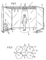
- la figure 1 est une vue en perspective montrant un abri pour voyageurs selon une forme de réalisation de l'invention,
- la figure 2 est une vue de détail de la face inférieure de l'abri de la figure 1,
- la figure 3 est une vue de dessus du toit de l'abri de la figure 1,
- et la figure 4 est un schéma bloc montrant le système de commande de l'éclairage de l'abri de la figure 1.
- Sur les différentes figures, les mêmes références désignent des éléments identiques ou similaires.
- La figure 1 représente un abri d'attente pour voyageurs de transports en commun 1 du type de ceux dénommés "abri bus"®. L'abri 1 comporte un toit 2 supporté par une structure 3 qui peut comprendre par exemple des poteaux 4, des parois latérales 5 vitrées ou autres et le cas échéant un panneau d'affichage 6 lumineux.
- Le panneau d'affichage 6 peut comporter par exemple au moins une face transparente 7 adaptée pour recevoir une affiche rétro éclairée par un dispositif d'éclairage 8 qui comporte par exemple plusieurs tubes néon 9.
- La face inférieure 10 du toit 2 comporte une pluralité de plaques modulaires 11 juxtaposées qui dans l'exemple considéré ici sont de forme hexagonale et peuvent présenter chacune une surface de l'ordre de 0,25 m2.
- Comme représenté sur les figures 1 et 2, chacune des plaques modulaires 11 peut comporter un point d'éclairage 12 adapté pour éclairer vers le bas, de préférence avec un éclairage directif. Les points d'éclairage 12 peuvent être formés par exemple par des diodes électroluminescentes de couleur blanche, ou autre.
- De plus, chacune des plaques modulaires 11 peut comporter un détecteur de présence 13, par exemple un détecteur de mouvements à infrarouge, qui est orienté vers le bas et qui est de préférence lui-même assez directif, de façon à détecter un voyageur V présent sous l'abri 1, uniquement si ce voyageur se trouve en correspondance avec le détecteur en question.
- Les détecteurs 13 peuvent être adaptés pour détecter une présence à partir d'une hauteur minimale au dessus du sol, cette hauteur minimale pouvant être par exemple comprise entre 30 cm et 120 cm : ainsi les détecteurs 13 peuvent détecter la présence d'un enfant ou d'un adulte, mais ne détectent pas la présence d'un animal tel qu'un chien de relativement petite taille ou un chat. Cette hauteur minimale de détection peut être obtenue par exemple en calibrant la sensibilité des détecteurs 13.
- En variante, les détecteurs 13 pourraient détecter une présence sous l'abri 1 sans hauteur minimale de détection, et l'abri 1 pourrait comporter un détecteur de présence supplémentaire (non représenté), orienté horizontalement et détectant tout mouvement à l'intérieur de l'abri 1 à partir d'une certaine hauteur minimale : dans ce cas, les détecteurs 13 disposés sous le toit de l'abri détecteraient uniquement la position d'une personne ou d'un animal présent sous l'abri, tandis que le détecteur orienté horizontalement vérifierait que la présence détectée est une présence humaine, en vérifiant que l'on détecte une présence à une hauteur suffisante au dessus du sol pour qu'il ne s'agisse pas d'un animal de petite taille tel qu'un chien ou un chat.
- Comme représenté sur la figure 3, l'ensemble des dispositifs électriques de l'abri 1 peut être alimenté électriquement par un dispositif d'alimentation photovoltaïque 15 disposé sur le toit 2 de l'abri et associé à une batterie 15a (figure 4).
- Comme représenté sur la figure 4, la batterie 15a peut alimenter le dispositif d'éclairage 8 du panneau 6, un dispositif de commande 16 tel qu'une unité centrale électronique (CPU) et un circuit d'alimentation électrique 17 qui est commandé par l'unité centrale 16 pour commander le fonctionnement des points lumineux 12 (L) ainsi que le niveau de puissance électrique délivré à chaque point lumineux 12.
- Les différents détecteurs de présence 13 (S) sont également reliés à l'unité centrale électronique 16, et ladite unité centrale électronique commande en outre le dispositif d'éclairage 8 du panneau 6. Eventuellement, l'unité centrale électronique 16 peut être reliée à une interface de communication 18 (COM1), par exemple une interface radio, qui est adaptée pour détecter la présence sous l'abri d'un dispositif d'identification portatif 19 (COM2) porté par exemple par des malvoyants.
- Le dispositif qui vient d'être décrit fonctionne comme suit :
- lorsqu'un détecteur 13 détecte un voyageur sous l'abri en période nocturne (il peut s'agir par exemple d'une tranche horaire prédéterminée mémorisée par l'unité centrale électronique 16, qui inclut classiquement une horloge électronique, ou d'une tranche horaire de fonctionnement de l'éclairage public, auquel l'abri peut être raccordé), l'unité centrale électronique 16 allume uniquement le ou les points lumineux disposés en correspondance avec le voyageur V (ou avec les voyageurs si plusieurs voyageurs sont repérés) ; si le ou les voyageurs V se déplacent sous l'abri, la zone éclairée 14 (figure 1) se déplace avec eux ;
- lorsque aucun détecteur 13 ne détecte de voyageur V sous l'abri, en période nocturne, l'unité centrale 16 est adaptée pour faire fonctionner les points lumineux selon un mode de veille à faible consommation.
- Dans ce mode de veille, l'unité centrale 16 peut être adaptée pour :
- soit éteindre tous les points lumineux 12,
- soit allumer au moins certains points lumineux 12 à basse puissance, et/ou allumer uniquement certains points lumineux 12 et/ou allumer tour à tour au moins certains des points lumineux 12.
- On notera par ailleurs que l'on peut faire fonctionner les points lumineux voisins du panneau d'affichage avec une puissance inférieure aux autres points lumineux, pour tenir compte de l'apport de lumière procuré par le panneau d'affichage 6.
- Par ailleurs, lorsque l'unité centrale 16 détecte un dispositif d'identification portatif 19 sous l'abri 1, elle peut être adaptée pour faire fonctionner les points lumineux 12 d'une façon spécifique, par exemple en augmentant le niveau d'éclairage sous l'abri.
- On notera enfin que les détecteurs 13 pourraient éventuellement être en nombre inférieur par rapport aux points lumineux 12, auquel cas plusieurs points lumineux 12 seraient affectés à un détecteur 13. De même, les points lumineux 12 et détecteurs 13 pourraient être installés sous le toit 2 autrement que sur les plaques modulaires 11 décrites ci-dessous.
Claims (16)
- Abri d'attente pour voyageurs comprenant un toit (2) sous lequel est disposée une pluralité de points lumineux électriques (12) commandés par un dispositif de commande (16),
caractérisé en ce qu'il comporte une pluralité de détecteurs de présence (13) adaptés pour détecter un voyageur (V) sous l'abri, le dispositif de commande (16) étant relié aux détecteurs (13) et étant adapté pour sélectivement commander au moins certains desdits point lumineux (12) en fonction de la détection ou non d'un voyageur (V) par les détecteurs (13) en correspondance avec lesdits points lumineux. - Abri selon la revendication 1, dans lequel chaque détecteur (13) est associé à au moins un point lumineux (12) et le dispositif de commande est adapté pour allumer ledit point lumineux (12), en période nocturne, lorsque ledit détecteur détecte un voyageur ;
- Abri selon la revendication 2, dans lequel chaque détecteur (13) est associé à un point lumineux (12) unique.
- Abri selon la revendication 2 ou la revendication 3, dans lequel chaque détecteur (13) est disposé sous le toit (2) de l'abri au voisinage dudit au moins un point lumineux (12) auquel il est associé.
- Abri selon la revendication 4, dans lequel le toit (2) de l'abri présente une face inférieure (10) comprenant une pluralité de plaques modulaires (11) juxtaposées qui comportent chacune un point lumineux (12) et un détecteur (13).
- Abri selon l'une quelconque des revendications précédentes, dans lequel le dispositif de commande (16) est adapté pour, lorsqu'un détecteur (13) détecte un voyageur (V) sous l'abri, allumer uniquement le ou les points lumineux (12) disposés en correspondance avec le voyageur (V), en période nocturne.
- Abri selon l'une quelconque des revendications précédentes, dans lequel le dispositif de commande (16) est adapté pour faire fonctionner les points lumineux (12) selon un mode de veille à faible consommation lorsque aucun détecteur (13) ne détecte de voyageur (V) sous l'abri, en période nocturne.
- Abri selon la revendication 7, dans lequel le dispositif de commande (16) est adapté pour éteindre tous les points lumineux (12) en mode de veille.
- Abri selon la revendication 7, dans lequel le dispositif de commande (16) est adapté pour allumer au moins certains points lumineux (12) à basse puissance en mode de veille.
- Abri selon la revendication 7, dans lequel le dispositif de commande (16) est adapté pour allumer uniquement certains points lumineux (12) en mode de veille.
- Abri selon la revendication 7, dans lequel le dispositif de commande (16) est adapté pour allumer tour à tour au moins certains des points lumineux (12) en mode de veille.
- Abri selon l'une quelconque des revendications précédentes, dans lequel les détecteurs (13) sont adaptés pour détecter une présence sous l'abri à partir d'une hauteur minimale comprise entre 30 et 120 cm au dessus du sol.
- Abri selon l'une quelconque des revendications précédentes, comportant un panneau d'affichage éclairé (6), le dispositif de commande (16) étant adapté pour faire fonctionner les points lumineux (12) voisins du panneau d'affichage (6) avec une puissance inférieure aux autres points lumineux (12).
- Abri selon l'une quelconque des revendications précédentes, dans lequel le dispositif de commande (16) est adapté pour détecter des dispositifs d'identification portatifs (19) portés par certains voyageurs et pour faire fonctionner les points lumineux (12) d'une façon spécifique lorsqu'un tel dispositif d'identification portatif (19) est détecté.
- Abri selon la revendication 14, dans lequel le dispositif de commande (16) est adapté pour augmenter le niveau d'éclairage sous l'abri (1) lorsqu'il détecte ledit dispositif d'identification portatif (19).
- Abri selon l'une quelconque des revendications précédentes, comportant un dispositif d'alimentation électrique photovoltaïque (15).
Applications Claiming Priority (1)
| Application Number | Priority Date | Filing Date | Title |
|---|---|---|---|
| FR0503099A FR2883956B1 (fr) | 2005-03-30 | 2005-03-30 | Abri d'attente pour voyageurs avec dispositif de commande de l'eclairage |
Publications (2)
| Publication Number | Publication Date |
|---|---|
| EP1707870A1 true EP1707870A1 (fr) | 2006-10-04 |
| EP1707870B1 EP1707870B1 (fr) | 2007-12-12 |
Family
ID=34954900
Family Applications (1)
| Application Number | Title | Priority Date | Filing Date |
|---|---|---|---|
| EP05077658A Expired - Lifetime EP1707870B1 (fr) | 2005-03-30 | 2005-11-23 | Abri d'attente pour voyageurs avec dispositif de commande de l'éclairage |
Country Status (4)
| Country | Link |
|---|---|
| EP (1) | EP1707870B1 (fr) |
| AT (1) | ATE380975T1 (fr) |
| DE (1) | DE602005003782D1 (fr) |
| FR (1) | FR2883956B1 (fr) |
Cited By (7)
| Publication number | Priority date | Publication date | Assignee | Title |
|---|---|---|---|---|
| WO2009133505A1 (fr) * | 2008-04-29 | 2009-11-05 | Philips Intellectual Property & Standards Gmbh | Unité d’éclairage sensible aux objets |
| EP2364068A1 (fr) * | 2010-02-26 | 2011-09-07 | Sanyo Electric Co., Ltd. | Appareil de contrôle d'éclairage |
| CN107366447A (zh) * | 2017-09-08 | 2017-11-21 | 李兴实 | 一种公汽车站候车亭太阳能发电及供电整套系统 |
| CN109944469A (zh) * | 2019-04-15 | 2019-06-28 | 王毅锋 | 人工智能生日房及其布置方法 |
| CN112815434A (zh) * | 2021-01-13 | 2021-05-18 | 杨清波 | 一种调光式室内空气净化设备 |
| CN112963024A (zh) * | 2021-02-05 | 2021-06-15 | 江西金信科技集团有限公司 | 模块化候车亭 |
| US20230295942A1 (en) * | 2020-08-06 | 2023-09-21 | Dwelling Co.,Ltd | Safety smart shelter for disaster evacuation |
Citations (4)
| Publication number | Priority date | Publication date | Assignee | Title |
|---|---|---|---|---|
| US4410930A (en) * | 1982-02-05 | 1983-10-18 | Gladwin, Inc. | Photo voltaic lighting for outdoor telephone booth |
| DE9315434U1 (de) * | 1993-10-08 | 1994-01-05 | Hillig, Horst, 10318 Berlin | Wartehäuschen für Haltestellen von öffentlichen Verkehrsmitteln |
| US5927026A (en) * | 1998-03-31 | 1999-07-27 | Durham; Timothy H. | Solar energy security bus shelter |
| WO2002081844A1 (fr) * | 2001-04-06 | 2002-10-17 | Thomas Emde | Meuble urbain presentant une vitre eclairee |
-
2005
- 2005-03-30 FR FR0503099A patent/FR2883956B1/fr not_active Expired - Lifetime
- 2005-11-23 AT AT05077658T patent/ATE380975T1/de not_active IP Right Cessation
- 2005-11-23 DE DE602005003782T patent/DE602005003782D1/de not_active Expired - Lifetime
- 2005-11-23 EP EP05077658A patent/EP1707870B1/fr not_active Expired - Lifetime
Patent Citations (4)
| Publication number | Priority date | Publication date | Assignee | Title |
|---|---|---|---|---|
| US4410930A (en) * | 1982-02-05 | 1983-10-18 | Gladwin, Inc. | Photo voltaic lighting for outdoor telephone booth |
| DE9315434U1 (de) * | 1993-10-08 | 1994-01-05 | Hillig, Horst, 10318 Berlin | Wartehäuschen für Haltestellen von öffentlichen Verkehrsmitteln |
| US5927026A (en) * | 1998-03-31 | 1999-07-27 | Durham; Timothy H. | Solar energy security bus shelter |
| WO2002081844A1 (fr) * | 2001-04-06 | 2002-10-17 | Thomas Emde | Meuble urbain presentant une vitre eclairee |
Cited By (9)
| Publication number | Priority date | Publication date | Assignee | Title |
|---|---|---|---|---|
| WO2009133505A1 (fr) * | 2008-04-29 | 2009-11-05 | Philips Intellectual Property & Standards Gmbh | Unité d’éclairage sensible aux objets |
| EP2364068A1 (fr) * | 2010-02-26 | 2011-09-07 | Sanyo Electric Co., Ltd. | Appareil de contrôle d'éclairage |
| US8456102B2 (en) | 2010-02-26 | 2013-06-04 | Sanyo Electric Co., Ltd. | Illumination control apparatus |
| CN107366447A (zh) * | 2017-09-08 | 2017-11-21 | 李兴实 | 一种公汽车站候车亭太阳能发电及供电整套系统 |
| CN109944469A (zh) * | 2019-04-15 | 2019-06-28 | 王毅锋 | 人工智能生日房及其布置方法 |
| US20230295942A1 (en) * | 2020-08-06 | 2023-09-21 | Dwelling Co.,Ltd | Safety smart shelter for disaster evacuation |
| US12442209B2 (en) * | 2020-08-06 | 2025-10-14 | Dwelling Co., Ltd | Safety smart shelter for disaster evacuation |
| CN112815434A (zh) * | 2021-01-13 | 2021-05-18 | 杨清波 | 一种调光式室内空气净化设备 |
| CN112963024A (zh) * | 2021-02-05 | 2021-06-15 | 江西金信科技集团有限公司 | 模块化候车亭 |
Also Published As
| Publication number | Publication date |
|---|---|
| EP1707870B1 (fr) | 2007-12-12 |
| DE602005003782D1 (de) | 2008-01-24 |
| FR2883956A1 (fr) | 2006-10-06 |
| ATE380975T1 (de) | 2007-12-15 |
| FR2883956B1 (fr) | 2007-06-15 |
Similar Documents
| Publication | Publication Date | Title |
|---|---|---|
| KR102037423B1 (ko) | 다기능 승강 폴 시스템 | |
| US6367180B2 (en) | Electronic illuminated house sign | |
| US6827445B2 (en) | Sun-tracking daylighting apparatus | |
| EP1707870B1 (fr) | Abri d'attente pour voyageurs avec dispositif de commande de l'éclairage | |
| KR101074116B1 (ko) | 가로등장치 | |
| CA2491104A1 (fr) | Utilisation de diodes electroluminescentes organiques (oled) dans des applications d'eclairage paysager | |
| DE69908908D1 (de) | Maschinenraumloses aufzugssystem mit aufzugsantrieb im aufzugskabine | |
| JP2004281327A (ja) | 照明灯装置 | |
| KR102477381B1 (ko) | 쉼터의자를 가진 태양광 보안 폴 시스템 | |
| FR2488014A1 (fr) | Dispositif indicateur lumineux | |
| US20110304273A1 (en) | Security lighting system | |
| EP0229802A1 (fr) | Dispositif de signalisation pour avertir de la traversee par un etre vivant de voies de circulation | |
| KR102159445B1 (ko) | 회전식 태양광 패널을 구비한 다기능 승강 폴 시스템 | |
| FR2937779A1 (fr) | Dispositif de treuil. | |
| KR102360401B1 (ko) | 배터리 잔량에 의한 밝기제어와 보행자 및 신호대기자 조사가 가능한 태양광 횡단보도 조명시스템 | |
| WO2008000933B1 (fr) | Dispositif d'affichage et utilisations de celui-ci | |
| EP3163714B1 (fr) | Luminaire de sécurité configurable | |
| EP3914046B1 (fr) | Système d' éclairage pour tunnel ou ouvrages similaires | |
| CN205480876U (zh) | 路灯检测装置 | |
| EP3162978B1 (fr) | Marquise dotee d'une cassette montee sur un support coulissant et d'un eclairage | |
| JP5459665B2 (ja) | 照明装置 | |
| LT5985B (lt) | Valdomas šviestuvas, skirtas lauko didelių plotų apšvietimui | |
| EP2892046A1 (fr) | Dispositif d'affichage, mobilier urbain comportant un tel dispositif d'affichage et utilisation d'un tel mobilier urbain | |
| JP3130218U (ja) | 防犯機能を持つ独立電源の照明灯 | |
| CH696514A5 (fr) | Parasol à éclairage solaire. |
Legal Events
| Date | Code | Title | Description |
|---|---|---|---|
| PUAI | Public reference made under article 153(3) epc to a published international application that has entered the european phase |
Free format text: ORIGINAL CODE: 0009012 |
|
| AK | Designated contracting states |
Kind code of ref document: A1 Designated state(s): AT BE BG CH CY CZ DE DK EE ES FI FR GB GR HU IE IS IT LI LT LU LV MC NL PL PT RO SE SI SK TR |
|
| AX | Request for extension of the european patent |
Extension state: AL BA HR MK YU |
|
| 17P | Request for examination filed |
Effective date: 20070402 |
|
| AKX | Designation fees paid |
Designated state(s): AT BE BG CH CY CZ DE DK EE ES FI FR GB GR HU IE IS IT LI LT LU LV MC NL PL PT RO SE SI SK TR |
|
| GRAP | Despatch of communication of intention to grant a patent |
Free format text: ORIGINAL CODE: EPIDOSNIGR1 |
|
| GRAS | Grant fee paid |
Free format text: ORIGINAL CODE: EPIDOSNIGR3 |
|
| GRAA | (expected) grant |
Free format text: ORIGINAL CODE: 0009210 |
|
| AK | Designated contracting states |
Kind code of ref document: B1 Designated state(s): AT BE BG CH CY CZ DE DK EE ES FI FR GB GR HU IE IS IT LI LT LU LV MC NL PL PT RO SE SI SK TR |
|
| REG | Reference to a national code |
Ref country code: GB Ref legal event code: FG4D Free format text: NOT ENGLISH |
|
| REG | Reference to a national code |
Ref country code: CH Ref legal event code: EP |
|
| REG | Reference to a national code |
Ref country code: IE Ref legal event code: FG4D Free format text: LANGUAGE OF EP DOCUMENT: FRENCH |
|
| REF | Corresponds to: |
Ref document number: 602005003782 Country of ref document: DE Date of ref document: 20080124 Kind code of ref document: P |
|
| PG25 | Lapsed in a contracting state [announced via postgrant information from national office to epo] |
Ref country code: SE Free format text: LAPSE BECAUSE OF FAILURE TO SUBMIT A TRANSLATION OF THE DESCRIPTION OR TO PAY THE FEE WITHIN THE PRESCRIBED TIME-LIMIT Effective date: 20080312 |
|
| PG25 | Lapsed in a contracting state [announced via postgrant information from national office to epo] |
Ref country code: LT Free format text: LAPSE BECAUSE OF FAILURE TO SUBMIT A TRANSLATION OF THE DESCRIPTION OR TO PAY THE FEE WITHIN THE PRESCRIBED TIME-LIMIT Effective date: 20071212 Ref country code: SI Free format text: LAPSE BECAUSE OF FAILURE TO SUBMIT A TRANSLATION OF THE DESCRIPTION OR TO PAY THE FEE WITHIN THE PRESCRIBED TIME-LIMIT Effective date: 20071212 Ref country code: NL Free format text: LAPSE BECAUSE OF FAILURE TO SUBMIT A TRANSLATION OF THE DESCRIPTION OR TO PAY THE FEE WITHIN THE PRESCRIBED TIME-LIMIT Effective date: 20071212 Ref country code: FI Free format text: LAPSE BECAUSE OF FAILURE TO SUBMIT A TRANSLATION OF THE DESCRIPTION OR TO PAY THE FEE WITHIN THE PRESCRIBED TIME-LIMIT Effective date: 20071212 Ref country code: LV Free format text: LAPSE BECAUSE OF FAILURE TO SUBMIT A TRANSLATION OF THE DESCRIPTION OR TO PAY THE FEE WITHIN THE PRESCRIBED TIME-LIMIT Effective date: 20071212 Ref country code: PL Free format text: LAPSE BECAUSE OF FAILURE TO SUBMIT A TRANSLATION OF THE DESCRIPTION OR TO PAY THE FEE WITHIN THE PRESCRIBED TIME-LIMIT Effective date: 20071212 |
|
| NLV1 | Nl: lapsed or annulled due to failure to fulfill the requirements of art. 29p and 29m of the patents act | ||
| PG25 | Lapsed in a contracting state [announced via postgrant information from national office to epo] |
Ref country code: AT Free format text: LAPSE BECAUSE OF FAILURE TO SUBMIT A TRANSLATION OF THE DESCRIPTION OR TO PAY THE FEE WITHIN THE PRESCRIBED TIME-LIMIT Effective date: 20071212 |
|
| GBV | Gb: ep patent (uk) treated as always having been void in accordance with gb section 77(7)/1977 [no translation filed] | ||
| PG25 | Lapsed in a contracting state [announced via postgrant information from national office to epo] |
Ref country code: ES Free format text: LAPSE BECAUSE OF FAILURE TO SUBMIT A TRANSLATION OF THE DESCRIPTION OR TO PAY THE FEE WITHIN THE PRESCRIBED TIME-LIMIT Effective date: 20080323 Ref country code: IS Free format text: LAPSE BECAUSE OF FAILURE TO SUBMIT A TRANSLATION OF THE DESCRIPTION OR TO PAY THE FEE WITHIN THE PRESCRIBED TIME-LIMIT Effective date: 20080412 Ref country code: CZ Free format text: LAPSE BECAUSE OF FAILURE TO SUBMIT A TRANSLATION OF THE DESCRIPTION OR TO PAY THE FEE WITHIN THE PRESCRIBED TIME-LIMIT Effective date: 20071212 |
|
| PG25 | Lapsed in a contracting state [announced via postgrant information from national office to epo] |
Ref country code: RO Free format text: LAPSE BECAUSE OF FAILURE TO SUBMIT A TRANSLATION OF THE DESCRIPTION OR TO PAY THE FEE WITHIN THE PRESCRIBED TIME-LIMIT Effective date: 20071212 Ref country code: SK Free format text: LAPSE BECAUSE OF FAILURE TO SUBMIT A TRANSLATION OF THE DESCRIPTION OR TO PAY THE FEE WITHIN THE PRESCRIBED TIME-LIMIT Effective date: 20071212 |
|
| PG25 | Lapsed in a contracting state [announced via postgrant information from national office to epo] |
Ref country code: PT Free format text: LAPSE BECAUSE OF FAILURE TO SUBMIT A TRANSLATION OF THE DESCRIPTION OR TO PAY THE FEE WITHIN THE PRESCRIBED TIME-LIMIT Effective date: 20080512 |
|
| REG | Reference to a national code |
Ref country code: IE Ref legal event code: FD4D |
|
| PLBE | No opposition filed within time limit |
Free format text: ORIGINAL CODE: 0009261 |
|
| STAA | Information on the status of an ep patent application or granted ep patent |
Free format text: STATUS: NO OPPOSITION FILED WITHIN TIME LIMIT |
|
| PG25 | Lapsed in a contracting state [announced via postgrant information from national office to epo] |
Ref country code: IE Free format text: LAPSE BECAUSE OF FAILURE TO SUBMIT A TRANSLATION OF THE DESCRIPTION OR TO PAY THE FEE WITHIN THE PRESCRIBED TIME-LIMIT Effective date: 20071212 Ref country code: DK Free format text: LAPSE BECAUSE OF FAILURE TO SUBMIT A TRANSLATION OF THE DESCRIPTION OR TO PAY THE FEE WITHIN THE PRESCRIBED TIME-LIMIT Effective date: 20071212 Ref country code: DE Free format text: LAPSE BECAUSE OF FAILURE TO SUBMIT A TRANSLATION OF THE DESCRIPTION OR TO PAY THE FEE WITHIN THE PRESCRIBED TIME-LIMIT Effective date: 20080313 |
|
| 26N | No opposition filed |
Effective date: 20080915 |
|
| PG25 | Lapsed in a contracting state [announced via postgrant information from national office to epo] |
Ref country code: GB Free format text: LAPSE BECAUSE OF FAILURE TO SUBMIT A TRANSLATION OF THE DESCRIPTION OR TO PAY THE FEE WITHIN THE PRESCRIBED TIME-LIMIT Effective date: 20071212 |
|
| PG25 | Lapsed in a contracting state [announced via postgrant information from national office to epo] |
Ref country code: GR Free format text: LAPSE BECAUSE OF FAILURE TO SUBMIT A TRANSLATION OF THE DESCRIPTION OR TO PAY THE FEE WITHIN THE PRESCRIBED TIME-LIMIT Effective date: 20080313 |
|
| PG25 | Lapsed in a contracting state [announced via postgrant information from national office to epo] |
Ref country code: EE Free format text: LAPSE BECAUSE OF FAILURE TO SUBMIT A TRANSLATION OF THE DESCRIPTION OR TO PAY THE FEE WITHIN THE PRESCRIBED TIME-LIMIT Effective date: 20071212 Ref country code: BG Free format text: LAPSE BECAUSE OF FAILURE TO SUBMIT A TRANSLATION OF THE DESCRIPTION OR TO PAY THE FEE WITHIN THE PRESCRIBED TIME-LIMIT Effective date: 20080312 |
|
| BERE | Be: lapsed |
Owner name: JCDECAUX SA Effective date: 20081130 |
|
| PG25 | Lapsed in a contracting state [announced via postgrant information from national office to epo] |
Ref country code: MC Free format text: LAPSE BECAUSE OF NON-PAYMENT OF DUE FEES Effective date: 20081130 |
|
| PG25 | Lapsed in a contracting state [announced via postgrant information from national office to epo] |
Ref country code: CY Free format text: LAPSE BECAUSE OF FAILURE TO SUBMIT A TRANSLATION OF THE DESCRIPTION OR TO PAY THE FEE WITHIN THE PRESCRIBED TIME-LIMIT Effective date: 20071212 |
|
| REG | Reference to a national code |
Ref country code: FR Ref legal event code: ST Effective date: 20090731 |
|
| PG25 | Lapsed in a contracting state [announced via postgrant information from national office to epo] |
Ref country code: BE Free format text: LAPSE BECAUSE OF NON-PAYMENT OF DUE FEES Effective date: 20081130 |
|
| REG | Reference to a national code |
Ref country code: CH Ref legal event code: PL |
|
| PG25 | Lapsed in a contracting state [announced via postgrant information from national office to epo] |
Ref country code: HU Free format text: LAPSE BECAUSE OF FAILURE TO SUBMIT A TRANSLATION OF THE DESCRIPTION OR TO PAY THE FEE WITHIN THE PRESCRIBED TIME-LIMIT Effective date: 20080613 Ref country code: LU Free format text: LAPSE BECAUSE OF NON-PAYMENT OF DUE FEES Effective date: 20081123 |
|
| PG25 | Lapsed in a contracting state [announced via postgrant information from national office to epo] |
Ref country code: TR Free format text: LAPSE BECAUSE OF FAILURE TO SUBMIT A TRANSLATION OF THE DESCRIPTION OR TO PAY THE FEE WITHIN THE PRESCRIBED TIME-LIMIT Effective date: 20071212 |
|
| PG25 | Lapsed in a contracting state [announced via postgrant information from national office to epo] |
Ref country code: CH Free format text: LAPSE BECAUSE OF NON-PAYMENT OF DUE FEES Effective date: 20091130 Ref country code: LI Free format text: LAPSE BECAUSE OF NON-PAYMENT OF DUE FEES Effective date: 20091130 |
|
| PG25 | Lapsed in a contracting state [announced via postgrant information from national office to epo] |
Ref country code: IT Free format text: LAPSE BECAUSE OF NON-PAYMENT OF DUE FEES Effective date: 20081130 |
|
| PG25 | Lapsed in a contracting state [announced via postgrant information from national office to epo] |
Ref country code: FR Free format text: LAPSE BECAUSE OF NON-PAYMENT OF DUE FEES Effective date: 20081130 |