EP1707808A2 - Füsse für eine Offshore-Windenergieanlage - Google Patents
Füsse für eine Offshore-Windenergieanlage Download PDFInfo
- Publication number
- EP1707808A2 EP1707808A2 EP06006287A EP06006287A EP1707808A2 EP 1707808 A2 EP1707808 A2 EP 1707808A2 EP 06006287 A EP06006287 A EP 06006287A EP 06006287 A EP06006287 A EP 06006287A EP 1707808 A2 EP1707808 A2 EP 1707808A2
- Authority
- EP
- European Patent Office
- Prior art keywords
- seabed
- foot
- feet
- wind turbine
- longitudinal direction
- Prior art date
- Legal status (The legal status is an assumption and is not a legal conclusion. Google has not performed a legal analysis and makes no representation as to the accuracy of the status listed.)
- Granted
Links
Images


Classifications
-
- F—MECHANICAL ENGINEERING; LIGHTING; HEATING; WEAPONS; BLASTING
- F03—MACHINES OR ENGINES FOR LIQUIDS; WIND, SPRING, OR WEIGHT MOTORS; PRODUCING MECHANICAL POWER OR A REACTIVE PROPULSIVE THRUST, NOT OTHERWISE PROVIDED FOR
- F03D—WIND MOTORS
- F03D13/00—Assembly, mounting or commissioning of wind motors; Arrangements specially adapted for transporting wind motor components
- F03D13/20—Arrangements for mounting or supporting wind motors; Masts or towers for wind motors
- F03D13/22—Foundations specially adapted for wind motors
-
- E—FIXED CONSTRUCTIONS
- E02—HYDRAULIC ENGINEERING; FOUNDATIONS; SOIL SHIFTING
- E02B—HYDRAULIC ENGINEERING
- E02B17/00—Artificial islands mounted on piles or like supports, e.g. platforms on raisable legs or offshore constructions; Construction methods therefor
-
- E—FIXED CONSTRUCTIONS
- E02—HYDRAULIC ENGINEERING; FOUNDATIONS; SOIL SHIFTING
- E02D—FOUNDATIONS; EXCAVATIONS; EMBANKMENTS; UNDERGROUND OR UNDERWATER STRUCTURES
- E02D27/00—Foundations as substructures
- E02D27/32—Foundations for special purposes
- E02D27/42—Foundations for poles, masts or chimneys
- E02D27/425—Foundations for poles, masts or chimneys specially adapted for wind motors masts
-
- E—FIXED CONSTRUCTIONS
- E02—HYDRAULIC ENGINEERING; FOUNDATIONS; SOIL SHIFTING
- E02D—FOUNDATIONS; EXCAVATIONS; EMBANKMENTS; UNDERGROUND OR UNDERWATER STRUCTURES
- E02D27/00—Foundations as substructures
- E02D27/32—Foundations for special purposes
- E02D27/52—Submerged foundations, i.e. submerged in open water
-
- F—MECHANICAL ENGINEERING; LIGHTING; HEATING; WEAPONS; BLASTING
- F03—MACHINES OR ENGINES FOR LIQUIDS; WIND, SPRING, OR WEIGHT MOTORS; PRODUCING MECHANICAL POWER OR A REACTIVE PROPULSIVE THRUST, NOT OTHERWISE PROVIDED FOR
- F03D—WIND MOTORS
- F03D13/00—Assembly, mounting or commissioning of wind motors; Arrangements specially adapted for transporting wind motor components
- F03D13/10—Assembly of wind motors; Arrangements for erecting wind motors
-
- E—FIXED CONSTRUCTIONS
- E02—HYDRAULIC ENGINEERING; FOUNDATIONS; SOIL SHIFTING
- E02B—HYDRAULIC ENGINEERING
- E02B17/00—Artificial islands mounted on piles or like supports, e.g. platforms on raisable legs or offshore constructions; Construction methods therefor
- E02B2017/0091—Offshore structures for wind turbines
-
- E—FIXED CONSTRUCTIONS
- E02—HYDRAULIC ENGINEERING; FOUNDATIONS; SOIL SHIFTING
- E02B—HYDRAULIC ENGINEERING
- E02B17/00—Artificial islands mounted on piles or like supports, e.g. platforms on raisable legs or offshore constructions; Construction methods therefor
- E02B2017/0095—Connections of subsea risers, piping or wiring with the offshore structure
-
- F—MECHANICAL ENGINEERING; LIGHTING; HEATING; WEAPONS; BLASTING
- F05—INDEXING SCHEMES RELATING TO ENGINES OR PUMPS IN VARIOUS SUBCLASSES OF CLASSES F01-F04
- F05B—INDEXING SCHEME RELATING TO WIND, SPRING, WEIGHT, INERTIA OR LIKE MOTORS, TO MACHINES OR ENGINES FOR LIQUIDS COVERED BY SUBCLASSES F03B, F03D AND F03G
- F05B2240/00—Components
- F05B2240/90—Mounting on supporting structures or systems
- F05B2240/91—Mounting on supporting structures or systems on a stationary structure
- F05B2240/912—Mounting on supporting structures or systems on a stationary structure on a tower
- F05B2240/9121—Mounting on supporting structures or systems on a stationary structure on a tower on a lattice tower
-
- F—MECHANICAL ENGINEERING; LIGHTING; HEATING; WEAPONS; BLASTING
- F05—INDEXING SCHEMES RELATING TO ENGINES OR PUMPS IN VARIOUS SUBCLASSES OF CLASSES F01-F04
- F05B—INDEXING SCHEME RELATING TO WIND, SPRING, WEIGHT, INERTIA OR LIKE MOTORS, TO MACHINES OR ENGINES FOR LIQUIDS COVERED BY SUBCLASSES F03B, F03D AND F03G
- F05B2240/00—Components
- F05B2240/90—Mounting on supporting structures or systems
- F05B2240/95—Mounting on supporting structures or systems offshore
-
- F—MECHANICAL ENGINEERING; LIGHTING; HEATING; WEAPONS; BLASTING
- F05—INDEXING SCHEMES RELATING TO ENGINES OR PUMPS IN VARIOUS SUBCLASSES OF CLASSES F01-F04
- F05B—INDEXING SCHEME RELATING TO WIND, SPRING, WEIGHT, INERTIA OR LIKE MOTORS, TO MACHINES OR ENGINES FOR LIQUIDS COVERED BY SUBCLASSES F03B, F03D AND F03G
- F05B2240/00—Components
- F05B2240/90—Mounting on supporting structures or systems
- F05B2240/96—Mounting on supporting structures or systems as part of a wind turbine farm
-
- Y—GENERAL TAGGING OF NEW TECHNOLOGICAL DEVELOPMENTS; GENERAL TAGGING OF CROSS-SECTIONAL TECHNOLOGIES SPANNING OVER SEVERAL SECTIONS OF THE IPC; TECHNICAL SUBJECTS COVERED BY FORMER USPC CROSS-REFERENCE ART COLLECTIONS [XRACs] AND DIGESTS
- Y02—TECHNOLOGIES OR APPLICATIONS FOR MITIGATION OR ADAPTATION AGAINST CLIMATE CHANGE
- Y02E—REDUCTION OF GREENHOUSE GAS [GHG] EMISSIONS, RELATED TO ENERGY GENERATION, TRANSMISSION OR DISTRIBUTION
- Y02E10/00—Energy generation through renewable energy sources
- Y02E10/70—Wind energy
- Y02E10/72—Wind turbines with rotation axis in wind direction
-
- Y—GENERAL TAGGING OF NEW TECHNOLOGICAL DEVELOPMENTS; GENERAL TAGGING OF CROSS-SECTIONAL TECHNOLOGIES SPANNING OVER SEVERAL SECTIONS OF THE IPC; TECHNICAL SUBJECTS COVERED BY FORMER USPC CROSS-REFERENCE ART COLLECTIONS [XRACs] AND DIGESTS
- Y02—TECHNOLOGIES OR APPLICATIONS FOR MITIGATION OR ADAPTATION AGAINST CLIMATE CHANGE
- Y02E—REDUCTION OF GREENHOUSE GAS [GHG] EMISSIONS, RELATED TO ENERGY GENERATION, TRANSMISSION OR DISTRIBUTION
- Y02E10/00—Energy generation through renewable energy sources
- Y02E10/70—Wind energy
- Y02E10/727—Offshore wind turbines
-
- Y—GENERAL TAGGING OF NEW TECHNOLOGICAL DEVELOPMENTS; GENERAL TAGGING OF CROSS-SECTIONAL TECHNOLOGIES SPANNING OVER SEVERAL SECTIONS OF THE IPC; TECHNICAL SUBJECTS COVERED BY FORMER USPC CROSS-REFERENCE ART COLLECTIONS [XRACs] AND DIGESTS
- Y02—TECHNOLOGIES OR APPLICATIONS FOR MITIGATION OR ADAPTATION AGAINST CLIMATE CHANGE
- Y02E—REDUCTION OF GREENHOUSE GAS [GHG] EMISSIONS, RELATED TO ENERGY GENERATION, TRANSMISSION OR DISTRIBUTION
- Y02E10/00—Energy generation through renewable energy sources
- Y02E10/70—Wind energy
- Y02E10/728—Onshore wind turbines
Definitions
- the invention relates to a wind turbine for offshore use according to the preamble of claim 1, a wind farm according to the preamble of claim 8 and a method for setting up a wind turbine.
- Wind energy plants are conventionally anchored in offshore use in the form of Einpfahlloisdonne in the seabed. Furthermore, Tripod indispensabledungen are known, wherein the foot of the wind turbine has three tetrahedral apart legs, which are each anchored in the seabed.
- Tripod indispensabledungen are known, wherein the foot of the wind turbine has three tetrahedral apart legs, which are each anchored in the seabed.
- a predominantly tensile and compressive load exposed truss structure are known by means of jackets.
- the hub height of the individual wind turbines above the sea surface should be about the same for optical reasons.
- the same penetration level at sea surface level e.g. the jetty at all wind turbines of the park are formed at the same height of the main structure.
- the natural vibration behavior of the system is less dependent on the height above the sea surface than on the height above the seabed.
- the natural vibration behavior of wind turbines must be recalculated each time a large number of turbines are set up at different sea depths.
- Obtaining an approximately equal hub height above the sea surface is at the o.g. Foundations elaborate, because the length of the tripod or the jacket must be adjusted to the overall site.
- JP 2003028046 A For example, a foundation is described for an offshore wind turbine having different height feet, with some feet located above the sea surface and some feet below the sea surface.
- the object is achieved in its first aspect by a wind turbine for offshore use with the features of claim 1.
- the wind power plant according to the invention stands on its feet in the longitudinal direction adjustable feet on the seabed.
- the longitudinal direction runs along the longitudinal direction of a tube tower of the wind turbine.
- components such as tubular tower, nacelle and support structure are preferably standardized, and the different seabed profile and the different depth of the sea at the site of each foot is compensated to achieve a given rotor hub height above the sea level by the different longitudinal extent of the feet.
- the leg ends have a standardized, preferably the same distance from the sea surface and the respective clearance between the leg end and a predetermined contact point on the seabed is filled by the foot compensating in its longitudinal extent this distance.
- the longitudinal extent of a foot corresponds to the difference between the sum of the height of the rotor hub over the sea level and the depth of the seabed at the predetermined contact point and the sum of the standardized lengths of tubular tower and support structure.
- the feet of a plant have a different longitudinal extent to align the plant in the longitudinal direction.
- the feet of a wind energy installation can have a different extent in the longitudinal direction of the wind energy installation with one another and the feet of different wind energy installations.
- the longitudinal direction of the erected wind turbine preferably runs substantially perpendicular to the sea surface.
- the wind turbine is preferably exclusively on your feet with your total weight.
- the support structure with longitudinally adapted and mounted feet to the site is navigable.
- the wind turbine with its tube tower and rotor is mounted on a lattice tower (jacket), which is located mostly below the sea surface and protrudes a little way above the sea surface.
- the lattice tower may have a plurality of legs, preferably exactly three or four legs, at each of whose ends one of the feet is arranged.
- the invention is also applicable to all other multi-legged support structures, e.g. Tripods, suitable.
- Another advantage in the length adjustment of the feet according to the invention consists in the small influence of the length adjustment on the height of the natural frequency, because the base of the spread legs is large. The natural vibration behavior essentially only needs to be calculated once for all the systems of a park.
- each of the feet has a spacing component that essentially determines the extent in the longitudinal direction, on each of which there is a leg of the lattice tower of the wind energy plant. It can, e.g. with appropriate floor profiles, also be sufficient to provide only one foot with a spacer component.
- the extension of the spacing element in the longitudinal direction is dimensioned so that the profile of the seabed is compensated and the longitudinal direction of the erected wind turbine runs substantially perpendicular to the sea surface.
- the spacer member is preferably located at the sea bottom end of the leg and intended for direct contact with the seabed.
- the spacer component can have a cavity which can be filled with heavy filling material, the extent of which in the longitudinal direction essentially determines the extent of the spacer component.
- heavy filling material there is preferably used concrete, high-strength mortar (grout), gravel, iron ore or other high-density ballast materials, e.g. Magna Dense or so-called "Orecrete" used.
- a filling line for the filling material opens into the cavity at best.
- ballasting In addition to ballasting, the filler also increases the stiffness and strength of the feet. A special synergetic effect of the ballast arises from the fact that at locations with large water depth, where consequently the burdens of the foundations are particularly high, also very large ballast chambers are available, which compensate for the additional burden of increased dead weight.
- At least two cavities are provided on each of the feet. It is at each foot one in the erected state of the wind turbine the Seabed averted cavity and a seabed facing cavity provided. Both cavities may be interconnected by a filling material conducting passage opening.
- the cavities facing away from the seabed different feet can be identical, so that the feet, at least in parts, are standardized and only the lower, the seabed facing cavity needs to be adapted in its longitudinal direction to the circumstances of the site.
- the cavity or the cavity can be filled with filler.
- the wind turbine has at least one filling line, preferably each leg has exactly one filling line for the filling material.
- the filling lines are provided inside each of the legs of the lattice tower.
- an exact filling of each of the feet is possible.
- a separate filling line opens into the cavity facing away from the seabed and into the cavity facing the seabed.
- the cavities facing away from the seabed are identical and thus allow further standardization and thus cost savings.
- Adjacent cavities may be connected to one another via a filling material-conducting passage opening. Both cavities are thus filled via the filling with grout. Air can escape from the cavities through air vents.
- each of the interconnected cavities has its own air outlet opening. The air outlet openings are preferably closable from the outside.
- Each of the feet may have a stop plate intended for contact with the seabed and intended to prevent further penetration of the foot into the seabed.
- the invention may protrude from the stop plate at least one projection, which is formed, for example, as a the stop plate outside at the edge circumferential wall ring.
- the wall ring is intended to penetrate into the seabed and prevent slippage of the foot in a horizontal direction.
- the projection or wall ring can have an extension of several, up to 20m in the longitudinal direction and give the foundation the character of a pile foundation.
- At least one foot preferably each of the feet, has a suction device, in particular a suction bell.
- the suction cup is in the erected state of the wind turbine facing the seabed and intended for contact with the seabed. It makes it possible to seize the foot equipped with her on the seabed and thus not only to counteract a horizontal displacement, but also a vertical displacement of the wind turbine. This allows a particularly firm and also easy to handle anchoring on the seabed.
- the suction cup is particularly suitable for anchoring the preferably four feet of the lattice tower described above.
- the suction cup may have the stop plate and the wall ring as Saugglockenwandung.
- a connecting piece for a vent hose is provided in the suction cup wall, preferably on the stop plate, in a preferred embodiment of the invention.
- the vent hose is z. B. passed through the lower cavity to the sea surface and connected there to a pump.
- the air can be sucked out of the suction cup and thus suck the foot by the forming in her vacuum on the one hand to the seabed until the stop plate comes into contact with the seabed, and on the other by the negative pressure forming in the suction bell also prevents vertical shifting and tilting of the wind turbine.
- the object is achieved in its second aspect by a wind farm for off-shore use with at least two wind turbines with a standing in the erected state substantially perpendicular to a sea surface longitudinal direction and with a support structure with multiple legs, at the ends sea bottom side one for each contact with the seabed certain foot is arranged, wherein the towers and the support structures have a standardized length and an equal height of the rotor hubs over the sea surface is predetermined.
- a particular caused by the depth and / or the relief of the seabed, different distance between the rotor hub and a predetermined contact point on the seabed, on which an associated individual foot is to touch the seabed, is compensated according to the invention by an adapted extension of the respective foot.
- the invention enables a cost reduction in the construction of wind farms.
- the favorable visual impression of the wind farm, which is caused by the same rotor hub height can also be standardized according to the invention when used, in particular in terms of length Towers and support structures are achieved.
- the towers and support structures are substantially even completely standardized and thus particularly cost-effective to manufacture.
- the differences in the distances between an externally predetermined height of the rotor hub over the sea surface and the seabed at the different sites of the various wind turbines, as well as the differences between the distances between rotor hub height and the predetermined contact points are compensated to achieve a same rotor hub height by feet adapted longitudinal extent.
- the rotor hub height above the sea surface is so high that none of the legs of one of the wind turbines would touch the seabed using the standardized tower and standard support structure.
- a foot is arranged at each of the leg ends, whose extension in the longitudinal direction corresponds to the clearance between the leg end and the contact point of the seabed.
- the longitudinal extent of a foot corresponds in each case to the difference between the sum of the height of the rotor hub above the sea level and the depth of the seabed above the contact point and the sum of the standardized lengths of tubular tower and support structure.
- the object is also achieved by a method having the features of claim 8.
- the contact points of the seabed at the site of the system are determined on which the individual feet will sit.
- the depth of the seabed is determined over each of the predetermined contact points.
- the length ie the extent of each foot in the longitudinal direction is determined.
- the use of the standardized support structure and the tower for each wind turbine, in particular a wind turbine park, is taken into account.
- the sum of the height of the rotor hub above the sea surface plus the depth of the seabed above the contact point for each foot is determined and subtracted therefrom the sum of standardized length of the support structure and the tower.
- the clearance corresponding to the difference between the leg end and contact point on the seabed corresponds to the extent of this foot in the longitudinal direction.
- the so, preferably different, extended feet are then mounted on the wind turbine, preferably at the end of the associated leg of the lattice mast of the wind turbine.
- the mounted and provided with buoyancy bodies lattice mast is then shipped with eg floating pontoons to the site and lowered there by appropriate venting of the buoyant body to the seabed.
- the feet reach the seabed each predetermined contact point.
- the feet also penetrate the dead weight the system and possibly by pre-installed for this purpose ballast so far into the seabed that the stop plate comes into contact with the seabed.
- About the intended filling line provided in the feet cavities are then filled with the above filling material, in particular Grout.
- the wind energy plant preferably each of the feet of the wind turbine, has a suction bell.
- the erected wind turbine is arranged on the seabed so that the suction bell with the seabed is substantially airtight.
- the suction cup is vented via a vent hose connected to it and the evolving vacuum sucks the foot into the seabed until the stop plate comes in contact with the seabed and stops the penetration of the foot into the seabed.
- the forming in the suction cup negative pressure gives the wind turbine an additional stability against displacement in the vertical direction and against tilting.
- the suction cup is vented, it is preferably sealed airtight to allow for short-term loads to build a vacuum.
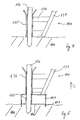
- the offshore wind turbine shown in Fig. 1 is placed by means of a lattice tower 130 on the seabed 100 at a site, and it has a here shown only schematically, above the sea surface 110 vertically towering tubular tower 120, with at one end of the seabed 100 arranged nacelle with rotor 121.
- a lattice tower 130 At the seabed 100 facing the end of the lattice tower 130 four feet 140 are mounted, with which the lattice tower 130 stands on the seabed 100.
- the tubular tower 120 extends along a longitudinal direction L of the wind turbine.
- the lattice tower 130 has four, preferably at an angle to the longitudinal direction L inclined legs 131 which are interconnected by a cross linkage 132.
- a connecting line between the bottom of the sea 100 opposite and the seabed 100 facing the end of the lattice 130 also extends along the longitudinal direction L.
- the lattice tower 130, the tubular tower 120 and the nacelle with rotor 121 are standardized.
- the rotor and a rotor hub associated therewith are designated by the same reference numeral 121.
- wind turbines designed for different sites may each have the same named standardized components 120, 121, 130, and they may nevertheless be installed in different water depths and different seabed profiles due to the different feet 140 adapted to the respective site.
- a comparison of the wind turbine in Fig. 2 with that in Fig. 1 shows that by extending the feet 140 in the longitudinal direction L of the wind turbine despite the larger water depth of the wind turbine in Fig. 1 identical lattice tower 130 can be used.
- the lattice towers 130 of both wind turbines in FIG. 1 and FIG. 2 nevertheless protrude beyond the sea surface 110 by approximately the same height.
- Fig. 3a is a detailed view of one of the feet 140 shown in Figs. 1 and 2.
- a leg 140 associated with the leg 131 is guided by a seabed 100 facing away from the cavity 141 and projects into a lower, the seabed 100 facing cavity 142 inside.
- the cavities 141, 142 are formed in a cross section parallel to the seabed 100 circular or polygonal and have in a 3-5 MW system transverse to the longitudinal direction L a diameter of 3m to 12m.
- the leg 131 is welded to walls of the cavity 141.
- the upper cavity 141 and the lower cavity 142 are connected by a through hole 143.
- the lower cavity 142 is extended up to 15 m in the longitudinal direction L.
- the lower cavity 142 is above one in the leg 131 guided filling line 133 through which filling material can flow, filled.
- filler is preferably special concrete, grout, gravel or iron ore, z. As Orecrete used.
- the filling line 133 may also have two separate filling lines, with which a separate filling, in particular by viscous filling material, both cavities 141, 142 is possible. Then, an air outlet opening may be provided in the lower cavity 142.
- the profile and depth of the seabed 100 at the site is determined.
- the lower cavity 142 is bounded on its seabed side by a stop plate 146.
- the position of the stop plate 146 in the longitudinal direction L of the foot 140 is adapted to the profile and depth of the seabed 100 at the site of the wind turbine.
- the distance between the sea surface 110 and the seabed 100 will depend on the exact location of each of the feet 140.
- the difference in distance difference is achieved by correspondingly different feet 140, d. H. by a different position of the stop plate 146 in the longitudinal direction of the foot 140, balanced.
- the stop plate 146 has a wall ring 147 which encircles the outside on the seabed side and which digs into the seabed 100 until the stop plate 146 rests on the seabed 100. He is not drawn to scale here.
- the wall ring 147 penetrates preferably up to 20 m into the seabed.
- the stop plate 146 prevents further introduction of the foot 140 into the seabed 100.
- the circumferential wall ring 147 prevents horizontal slippage of the foot 140th
- FIG. 3 b shows an embodiment of a foot according to the invention modified from the embodiment shown in FIG. 3 a.
- the filling line 133 is guided outside of the leg 131.
- a cable harness with lines for the removal of the generated power, and lines for controlling and monitoring the wind turbine is performed in the leg 131.
- the protected and easy installation of the cable harness is important for the reliable operation of the system.
- a so-called J-tube 205 connects to the leg 131 at the sea bottom end.
- the J-tube 205 pierces the wall of the cavity 142 at a slightly loaded point, just above or below the seabed 100.
- the J-tube 205 is followed by a tube 210 on the side facing away from the leg 131.
- a pull rope 215 through the leg 131, the J-tube 205 and the hose 210 threaded.
- a fastening element 216 is provided for the cable harness, which can then be pulled by means of the pull cable through the hose 210, the J-tube 205 and the leg 133 of the erected wind turbine.
- a method for setting up the wind turbine can proceed as follows: The lattice tower 130 is placed with luftbe spallbaren buoyancy aids to the site and there discharged by controlled air from the buoyancy aids placed on his feet 140 at the intended location on the seabed 100. After the wind turbine is placed on the feet 140, the Grout is passed through the guided through the legs 131 filling 133 into the lower cavity 142. The tubular leg 131 can also be used in its entirety as a filling line. A separate filling line 133 is then no longer necessary. The displaced by the filled Grout air flows through the passage opening 143 and out of the air outlet opening 145 from the lower cavity 142 and upper cavity 141 out.
- the groove passes through the passage opening 143 in the upper cavity 141 and fills this also with Grout.
- the air in the upper cavity 141 can escape through the upper air outlet opening 145 until the upper cavity 141 is completely filled with Grout. Possibly. the upper air outlet opening 145 is closed.
- the filling of the feet 140 with Grout increases the tipping stability of the system. The filling thus counteracts the vertical as well as the horizontal slippage of the foot 140.
- the filling of the feet can alternatively be done on land. Combinations of both methods are conceivable, i. Partial filling on land, flooding and residual ballast on site can be advantageous depending on the depth of the water, the buoyancy of the buoyancy aids and other site conditions.
- the filling of a cavity 141, 142 as a 7 m diameter cylinder with a diameter of 8 m with Magna Dense results in a ballast of 1100 t per foot.
- the vertical slippage of the wind turbine counteracts a selectively arranged on the stop plate 146 suction cup 146, 147.
- the suction cup 146, 147 makes it possible to suck the foot 140 to the seabed 100 and thus to stabilize in an additional way.
- the suction cup 146, 147 is shown in particular in FIGS. 1 to 3.
- the suction cup 146, 147 is substantially through the stop plate 146th and the peripheral ring around them, with the stop plate 146 airtight final wall ring 147 formed.
- the stop plate 146 has an opening which is formed as a connecting piece for a vent hose or line 148.
- the vent hose 148 is led out in sections through the lower cavity 142 and out through a lateral wall from the lower cavity 142 to the sea surface 110. Above the sea surface 110, the vent hose 148 is connected to a pump.
- the air out of the suction cup 146, 147 placed on the seabed 100 the foot 140 is sucked to the seabed 100 until the stop plate 146 comes into contact with the seabed 100, on the other hand creates a negative pressure, which is a displacement of the foot perpendicular to the seabed, ie in the vertical direction prevented.
- a negative pressure which is a displacement of the foot perpendicular to the seabed, ie in the vertical direction prevented.
- FIG. 4 shows another known embodiment of a foot 140, with which lattice towers 130 of conventional wind energy plants are anchored in the seabed 100.
- Each of the legs 131 of the lattice tower 130 is connected by lateral braces 134 to a guide 135 for a herring 136.
- the herring 136 has a diameter of up to three meters and a length of several, up to eighty meters.
- the herring 136 is driven into the seabed 100 in the guide 135 and anchors the leg 131 so tightly in the seabed 100.
- the carrying capacities of the herring 136 are different in tension and compression, i. the tensile strength is below the compressive strength.
- the ballasted spacer component 141, 142 can also be used in a particularly advantageous embodiment to reduce the tensile load of the design. This can also be done independently of a required length variability. The minimum extension in the longitudinal direction L of the spacer member 141, 142 and thus the amount of ballast can then be selected at each location, especially at low water depth locations just so that the required length of the herring 136 is equal to stress on train and pressure and the herring 136 is thus economically optimized.
- FIG. 5 shows an embodiment of the further embodiment of the foot 140 according to the invention.
- the sea floor side of the leg 131 and the guide 135 are provided with a cavity 141 which can be filled with grout in the leg 131 on the inside.
- the cavity 141 has a passage 137 in aligned extension of the guide 135 for the herring 136.
- the herring 136 in FIG. 5 is, so that a penetration depth corresponding to the embodiment in FIG. 4 is achieved in the seabed 100, by the length of the Cavity 141 in the longitudinal direction L longer than the herring 136 in Fig. 4.
- the lower wall of the cavity 141 in Fig. 5 is also formed as a stop plate 146 and limits the penetration depth of the foot 140 in the seabed 100.
- the stop plate 146 has a on Edge outer circumferential wall ring 147, which digs into the seabed 100 and prevents horizontal slippage of the foot 140. Also in this embodiment, stop plate 146 and wall ring 147 may be parts of a suction cup.
Landscapes
- Engineering & Computer Science (AREA)
- General Engineering & Computer Science (AREA)
- Life Sciences & Earth Sciences (AREA)
- Structural Engineering (AREA)
- Civil Engineering (AREA)
- Paleontology (AREA)
- Mechanical Engineering (AREA)
- General Life Sciences & Earth Sciences (AREA)
- Mining & Mineral Resources (AREA)
- Combustion & Propulsion (AREA)
- Chemical & Material Sciences (AREA)
- Sustainable Energy (AREA)
- Sustainable Development (AREA)
- Wind Motors (AREA)
- Other Liquid Machine Or Engine Such As Wave Power Use (AREA)
- Power-Operated Mechanisms For Wings (AREA)
Abstract
Description
- Die Erfindung betrifft eine Windenergieanlage für den Offshore-Einsatz nach dem Oberbegriff des Anspruchs 1, einen Windpark nach dem Oberbegriff des Anspruchs 8 und ein Verfahren zum Aufstellen einer Windenergieanlage.
- Windenergieanlagen werden herkömmlicher Weise im Offshore-Einsatz in Form von Einpfahlgründungen im Meeresboden verankert. Weiterhin sind Tripodgründungen bekannt, wobei der Fuß der Windenergieanlage drei tetraederförmig auseinander laufende Beine aufweist, die jeweils im Meeresboden verankert werden. Darüber hinaus sind bei Ölplattformen Gründungen mittels Jackets bekannt, einer vorwiegend Zug- und Druckbelastung ausgesetzten Fachwerkkonstruktion.
- Insbesondere bei Windenergieanlagenparks im Offshore-Bereich ist zu berücksichtigen, dass die Nabenhöhe der einzelnen Windenergieanlagen über der Meeresoberfläche zum einen aus optischen Gründen etwa gleich hoch sein sollte. Zum anderen können durch die gleiche Durchdringungshöhe auf Meeresoberflächenniveau z.B. die Bootsanleger an allen Windenergieanlagen des Parks in gleicher Höhe der Hauptkonstruktion ausgebildet werden. Das Eigenschwingungsverhalten der Anlage ist weniger von der Höhe über der Meeresoberfläche als vielmehr von der Höhe über dem Meeresboden abhängig. Somit muss das Eigenschwingungsverhalten der Windenergieanlagen, wenn eine Vielzahl von Anlagen in verschiedenen Meerestiefen aufgestellt wird, jedes Mal neu berechnet werden. Die Erzielung einer in etwa gleichen Nabenhöhe über der Meeresoberfläche ist bei den o.g. Gründungen aufwendig, denn die Länge des Tripods oder die des Jackets muss insgesamt dem Aufstellungsort angepasst werden.
- Aus der
WO 03/080939 A1 - In der
DE 201 00 588 U1 ist eine Offshore-Windenergieanlage offenbart, die mit Wasser flutbare Füße aufweist. Durch das Fluten der Füße ist der Fuß der Windenergieanlage gesteuert absenkbar. - Aus der
US 4,590,718 ist das Fundament einer Onshore-Windenergieanlage bekannt. Das Gewicht der Windenergieanlage wird über einen Turm auf den Boden abgegeben, wobei seitliche, in der Höhe verstellbare Füße die Gesamtkonstruktion stabilisieren. - In der
JP 2003028046 A - Es ist somit in einem ersten Aspekt Aufgabe der Erfindung, eine Windenergieanlage für den Offshore-Einsatz zur Verfügung zu stellen, bei der wesentliche Teile standardisiert sind und keine individuellen Auslegungsberechnungen der Gesamtstruktur erfordern, und es ist in einem zweiten Aspekt Aufgabe der Erfindung, ein Verfahren zum Aufstellen einer solchen Windenergieanlage zur Verfügung zu stellen.
- Die Aufgabe wird in ihrem ersten Aspekt durch eine Windenergieanlage für den Offshore-Einsatz mit den Merkmalen des Anspruchs 1 gelöst. Die erfindungsgemäße Windenergieanlage steht auf in ihrer Ausdehnung in Längsrichtung angepassbaren Füßen auf dem Meeresboden. Die Längsrichtung verläuft entlang der Längsrichtung eines Rohrturms der Windenergieanlage. Dabei sind Bauteile wie z.B. Rohrturm, Maschinenhaus und Trägerstruktur vorzugsweise standardisiert, und das unterschiedliche Meeresbodenprofil und die unterschiedliche Tiefe des Meeres am Aufstellungsort jedes Fußes wird zur Erzielung einer vorgegebenen Rotornabenhöhe über dem Meeresspiegel durch die unterschiedliche Längsausdehnung der Füße ausgeglichen. Die Beinenden haben einen standardisierten, vorzugsweise den gleichen Abstand zur Meeresoberfläche und der jeweilige lichte Abstand zwischen Beinende und einem vorbestimmten Kontaktpunkt am Meeresboden ist durch den in seiner Längsausdehnung diesen Abstand ausgleichenden Fuß aufgefüllt. Die Längsausdehnung eines Fußes entspricht dabei der Differenz zwischen der Summe aus der Höhe der Rotornabe über dem Meeresspiegel und der Tiefe des Meeresbodens am vorbestimmten Kontaktpunkt und der Summe der standardisierten Längen von Rohrturm und Trägerstruktur. Vorzugsweise haben die Füße einer Anlage eine unterschiedliche Längsausdehnung, um die Anlage in Längsrichtung auszurichten. Dabei können die Füße einer Windenergieanlage untereinander und die Füße verschiedener Windenergieanlagen eine unterschiedliche Ausdehnung in Längsrichtung der Windenergieanlage aufweisen. Die Längsrichtung der aufgestellten Windenergieanlage verläuft vorzugsweise im Wesentlichen senkrecht zur Meeresoberfläche. Die Windenergieanlage steht mit Ihrem Gesamtgewicht vorzugsweise ausschließlich auf den Füßen. Vorzugsweise ist die Trägerstruktur mit in Längsrichtung angepassten und montierten Füßen zum Aufstellungsort schiffbar.
- Vorzugsweise ist die Windenergieanlage mit ihrem Rohrturm und Rotor auf einem Gitterturm (Jacket) montiert, der großteils unter der Meeresoberfläche aufgestellt ist und ein Stück weit oberhalb der Meeresoberfläche herausragt. Der Gitterturm kann eine Mehrzahl von Beinen, vorzugsweise genau drei oder vier Beine, aufweisen, an deren Enden jeweils einer der Füße angeordnet ist. Die Erfindung ist aber auch für alle anderen mehrbeinigen Trägerstrukturen, z.B. Tripods, geeignet. Ein weiterer Vorteil in der erfindungsgemäßen Längenanpassung der Füße besteht in dem geringen Einfluss der Längenanpassung auf die Höhe der Eigenfrequenz, weil die Grundfläche der gespreizten Beine groß ist. Das Eigenschwingungsverhalten braucht im Wesentlichen nur einmal für alle Anlagen eines Parks berechnet zu werden.
- Vorteilhafterweise weisen die Füße jeweils ein die Ausdehnung in Längsrichtung im Wesentlichen bestimmendes Abstandsbauteil auf, auf dem jeweils ein Bein des Gitterturms der Windenergieanlage steht. Es kann, z.B. bei entsprechenden Bodenprofilen, auch ausreichend sein, nur einen Fuß mit einem Abstandsbauteil zu versehen. Die Ausdehnung des Abstandsbauteils in Längsrichtung ist so bemessen, dass das Profil des Meeresbodens ausgeglichen wird und die Längsrichtung der aufgestellten Windenergieanlage im Wesentlichen senkrecht zur Meeresoberfläche verläuft. Das Abstandbauteil ist vorzugsweise am meeresbodenseitigen Ende des Beins angeordnet und zum direkten Kontakt mit dem Meeresboden bestimmt.
- In einer vorteilhaften Weiterbildung der Erfindung kann das Abstandsbauteil einen mit schwerem Füllmaterial befüllbaren Hohlraum aufweisen, dessen Ausdehnung in Längsrichtung im Wesentlichen die Ausdehnung des Abstandsbauteils bestimmt. Als Füllmaterial wird vorzugsweise spezieller Beton, hochfester Mörtel (Grout), Kies, Eisenerz oder andere Ballastmaterialien mit hoher Dichte, z.B. Magna Dense oder so genannter "Orecrete" verwendet. Eine Befüllleitung für das Füllmaterial mündet günstigenfalls in den Hohlraum.
- Neben der Ballastierung erhöht das Füllmaterial auch die Steifigkeit und Festigkeit der Füße. Ein besonderer Synergieeffekt bei der Ballastierung entsteht dadurch, dass an Standorten mit großer Wassertiefe, an denen folglich auch die Belastungen der Gründungen besonders hoch sind, auch besonders große Ballastkammern zur Verfügung stehen, die die zusätzlichen Belastungen durch erhöhtes Eigengewicht kompensieren.
- Günstigenfalls sind an jedem der Füße wenigstens zwei Hohlräume vorgesehen. Dabei ist an jedem Fuß jeweils ein im aufgestellten Zustand der Windenergieanlage dem Meeresboden abgewandter Hohlraum und ein dem Meeresboden zugewandter Hohlraum vorgesehen. Beide Hohlräume können durch eine Füllmaterial leitende Durchlassöffnung miteinander verbunden sein. In Herstellungskosten sparender Weise können die dem Meeresboden abgewandten Hohlräume verschiedener Füße baugleich sein, so dass auch die Füße, zumindest in Teilen, standardisierbar sind und nur der untere, dem Meeresboden zugewandte Hohlraum braucht in seiner Längsrichtung den Gegebenheiten des Aufstellungsortes angepasst werden. Nachdem die Windenergieanlage auf dem Meeresboden am vorbestimmten Aufstellungsort aufgestellt ist, können die oder der Hohlraum mit Füllmaterial befüllt werden. Dazu weist die Windenergieanlage wenigstens eine Befüllleitung, vorzugsweise weist jedes Bein genau eine Befüllleitung für das Füllmaterial auf. Vorzugsweise sind die Befüllleitungen innen an jedem der Beine des Gitterturmes vorgesehen. Dadurch ist eine exakte Befüllung jedes der Füße möglich. Es ist auch denkbar, dass eine separate Befüllleitung in den dem Meeresboden abgewandten Hohlraum und in den dem Meeresboden zugewandten Hohlraum mündet.
- Vorteilhafter Weise sind die dem Meeresboden abgewandten Hohlräume baugleich und ermöglichen so eine weitere Standardisierung und damit Kosteneinsparung.
- Benachbarte Hohlräume können über eine Füllmaterial leitende Durchlassöffnung miteinander verbunden sein. Beide Hohlräume sind somit über die Befüllleitung mit Grout befüllbar. Luft kann aus den Hohlräumen durch Luftauslassöffnungen entweichen. Vorzugsweise weist jeder der miteinander verbunden Hohlräume eine eigene Luftausgangsöffnung auf. Die Luftausgangsöffnungen sind vorzugsweise von außen verschließbar.
- Jeder der Füße kann eine Stoppplatte aufweisen, die zum Kontakt mit dem Meeresboden bestimmt ist und die ein darüber hinaus gehendes Eindringen des Fußes in den Meeresboden verhindern soll.
- In einer weiteren Ausführungsform der Erfindung kann von der Stoppplatte wenigstens ein Vorsprung abstehen, der beispielsweise als ein die Stoppplatte außen am Rand umlaufender Wandungsring ausgebildet ist. Der Wandungsring ist dazu bestimmt, in den Meeresboden einzudringen und ein Verrutschen des Fußes in horizontaler Richtung zu verhindern. Der Vorsprung oder Wandungsring kann dabei in Längsrichtung eine Ausdehnung von mehreren, bis zu 20m haben und der Gründung den Charakter einer Pfahlgründung geben.
- In einer vorteilhaften Weiterbildung der Erfindung weist wenigstens ein Fuß, vorzugsweise jeder der Füße, eine Saugeinrichtung, insbesondere eine Saugglocke auf. Die Saugglocke ist im aufgestellten Zustand der Windenergieanlage dem Meeresboden zugewandt und zum Kontakt mit dem Meeresboden bestimmt. Sie ermöglicht es, den mit ihr ausgestatteten Fuß am Meeresboden festzusaugen und so nicht nur einer horizontalen Verschiebung, sondern auch einer vertikalen Verschiebung der Windenergieanlage entgegenzuwirken. Damit wird eine besonders feste und darüber hinaus einfach zu handhabende Verankerung am Meeresboden ermöglicht.
- Die Saugglocke eignet sich besonders zur Verankerung der vorzugsweise vier Füße des oben beschriebenen Gitterturmes. Die Saugglocke kann die Stoppplatte und den Wandungsring als Saugglockenwandung aufweisen. In der Saugglockenwandung, vorzugsweise an der Stoppplatte, ist, in einer bevorzugten Ausführungsform der Erfindung, ein Anschlussstutzen für einen Entlüftungsschlauch vorgesehen. Der Entlüftungsschlauch ist z. B. durch den unteren Hohlraum hindurch zur Meeresoberfläche geführt und dort an einer Pumpe angeschlossen. Nachdem die Windenergieanlage auf dem Meeresboden aufgestellt ist, kann die Luft aus der Saugglocke abgesaugt werden und somit den Fuß durch den sich in ihr ausbildenden Unterdruck zum einen an den Meeresboden heransaugen, bis die Stoppplatte mit dem Meeresboden in Kontakt gerät, und zum anderen wird durch den sich in der Saugglocke ausbildenden Unterdruck auch ein vertikales Verrücken und Kippen der Windenergieanlage verhindert.
- Die Aufgabe wird in Ihrem zweiten Aspekt durch einen Windpark für den off-shore Einsatz mit wenigstens zwei Windenergieanlagen mit einer im aufgestellten Zustand im Wesentlichen senkrecht zu einer Meeresoberfläche verlaufenden Längsrichtung und mit einer Trägerstruktur mit mehreren Beinen gelöst, an deren Enden meeresbodenseitig jeweils ein zum Kontakt mit dem Meeresboden bestimmter Fuß angeordnet ist, wobei die Türme und die Trägerstrukturen eine standardisierte Länge aufweisen und eine gleiche Höhe der Rotornaben über der Meeresoberfläche vorgegeben ist. Ein insbesondere durch die Tiefe und/oder das Relief des Meeresbodens verursachter, unterschiedlicher Abstand zwischen der Rotornabe und einem vorbestimmten Kontaktpunkt am Meeresboden, an dem jeweils eine zugehöriger einzelnen Fußes mit dem Meeresboden aufsetzen soll, ist erfindungsgemäß durch eine angepasste Ausdehnung des jeweiligen Fußes ausgeglichen.
- Die Erfindung ermöglicht eine Kostenreduzierung beim Aufbau von Windparks. Der durch eine gleiche Rotornabenhöhe bewirkte günstige optische Eindruck des Windparks kann erfindungsgemäß auch bei der Verwendung insbesondere in der Länge standardisierte Türme und Trägerstrukturen erzielt werden. Vorzugsweise sind die Türme und Trägerstrukturen im Wesentlichen sogar vollständig standardisiert und damit in der Herstellung besonders kostengünstig. Die Differenzen der Abstände zwischen einer extern vorgegebenen Höhe der Rotornabe über der Meeresoberfläche und dem Meeresboden an den unterschiedlichen Aufstellungsorten der verschiedenen Windenergieanlagen, als auch die Differenzen der Abstände zwischen Rotornabenhöhe und den vorbestimmten Kontaktpunkten werden zur Erzielung einer gleichen Rotornabenhöhe durch Füße angepasster Längsausdehnung ausgeglichen.
- Die Rotornabenhöhe über der Meeresoberfläche ist so hoch gewählt, dass keines der Beine einer der Windenergieanlagen bei der Verwendung des standardisierten Turmes und der standardisierten Trägerstruktur den Meeresboden berühren würde. Meeresbodenseitig ist an jedem der Beinenden ein Fuß angeordnet, dessen Ausdehnung in Längsrichtung dem lichten Abstand zwischen dem Beinende und dem Kontaktpunkt des Meeresbodens entspricht. Die Längsausdehnung eines Fußes entspricht dabei jeweils der Differenz zwischen der Summe aus der Höhe der Rotornabe über dem Meeresspiegel und der Tiefe des Meeresbodens über dem Kontaktpunkt und der Summe der standardisierten Längen von Rohrturm und Trägerstruktur.
- Die Aufgabe wird auch durch ein Verfahren mit den Merkmalen des Anspruchs 8 gelöst. Zunächst werden die Kontaktpunkte des Meersbodens am Aufstellungsort der Anlage bestimmt, auf denen die einzelnen Füße aufsetzen werden. Dann wird die Tiefe des Meeresbodens über jedem der vorbestimmten Kontaktpunkt bestimmt. Aus den gewonnenen Ergebnissen wird die Länge, d. h. die Ausdehnung jedes Fußes in Längsrichtung bestimmt. Dabei wird die Verwendung der standardisierten Trägerstruktur und des Turmes für jede Windenergieanlage, insbesondere eines Windenergieanlagenparks, berücksichtigt. Dazu wird die Summe aus Höhe der Rotornabe über der Meeresoberfläche zuzüglich der Tiefe des Meeresboden über dem Kontaktpunkt für jeden Fuß bestimmt und davon die Summe aus standardisierter Länge der Trägerstruktur und des Turmes abgezogen. Der der Differenz entsprechende lichte Abstand zwischen Beinende und Kontaktpunkt am Meeresboden entspricht der Ausdehnung dieses Fußes in Längsrichtung. Die so, vorzugsweise unterschiedlich, ausgedehnten Füße werden dann an der Windenergieanlage, vorzugsweise am Ende des zugehörigen Beines des Gittermastes der Windenergieanlage montiert. Der montierte und mit Auftriebskörpern versehene Gittermast wird dann mit z.B. Schwimmpontons zum Aufstellungsort geschifft und dort durch entsprechendes Entlüften der Auftriebskörper zum Meeresboden herabgelassen. Die Füße erreichen am Meeresboden den jeweils vorbestimmten Kontaktpunkt. Die Füße dringen auch durch das Eigengewicht der Anlage und ggf. durch zu diesem Zweck vorinstallierten Ballast soweit in den Meeresboden ein, dass die Stoppplatte mit dem Meeresboden in Kontakt gerät. Über die vorgesehene Befüllleitung werden die in den Füßen vorgesehenen Hohlräume dann mit dem o.g. Füllmaterial, insbesondere Grout, befüllt.
- In einer bevorzugten Ausführungsform des erfindungsgemäßen Verfahrens weist die Windenergieanlage, vorzugsweise jeder der Füße der Windenergieanlage, eine Saugglocke auf. Die aufgestellte Windenergieanlage wird so am Meeresboden angeordnet, dass die Saugglocke mit dem Meeresboden im Wesentlichen luftdicht abschließt. Dann wird die Saugglocke über einen mit ihr verbundenen Entlüftungsschlauch entlüftet und der sich ausbildende Unterdruck saugt den Fuß in den Meeresboden hinein, bis die Stoppplatte mit dem Meeresboden in Kontakt gerät und den Eindringvorgang des Fußes in den Meeresboden stoppt. Der sich in der Saugglocke ausbildende Unterdruck gibt der Windenergieanlage eine zusätzliche Stabilität gegen ein Verrücken in vertikaler Richtung und gegen ein Verkippen. Nachdem die Saugglocke entlüftet ist, wird sie vorzugsweise luftdicht verschlossen, um für kurzzeitige Belastungen den Aufbau eines Unterdrucks zu ermöglichen.
- Die Erfindung wird anhand von Ausführungsbeispielen in fünf Figuren beschrieben. Dabei zeigen:
- Fig. 1
- eine schematische Seitenansicht einer erfindungsgemäßen Offshore-Windenergieanlage an einem flachen Aufstellungsort,
- Fig.2
- eine schematische Seitenansicht einer erfindungsgemäßen Offshore-Windenergieanlage an einem tiefen Aufstellungsort,
- Fig. 3a
- eine Detailansicht eines Fußes einer ersten Ausführungsform in Fig. 1,
- Fig. 3b
- eine Detailansicht eines Fußes einer abgewandelten ersten Ausführungsform gemäß Fig.1,
- Fig. 4
- einen herkömmlichen Fuß einer zweiten Ausführungsform einer Offshore-Windenergieanlage,
- Fig. 5
- einen erfindungsgemäßen Fuß einer zweiten Ausführungsform einer Offshore-Windenergieanlage
- Die in Fig. 1 gezeigte Offshore-Windenergieanlage ist mittels eines Gitterturms 130 auf dem Meeresboden 100 an einem Aufstellungsort aufgestellt, und sie weist einen hier nur schematisch dargestellten, oberhalb der Meeresoberfläche 110 vertikal aufragenden Rohrturm 120 auf, mit an einem dem Meeresboden 100 gegenüberliegenden Ende angeordneten Maschinenhaus mit Rotor 121. An dem Meeresboden 100 zugewandten Ende des Gitterturms 130 sind vier Füße 140 montiert, mit denen der Gitterturm 130 auf dem Meeresboden 100 steht.
- Der Rohrturm 120 verläuft entlang einer Längsrichtung L der Windenergieanlage. Der Gitterturm 130 weist vier, vorzugsweise in gleichem Winkel zur Längsrichtung L geneigte Beine 131 auf, die durch ein Kreuzgestänge 132 miteinander verbunden sind. Eine Verbindungslinie zwischen dem dem Meeresboden 100 gegenüberliegenden und dem dem Meeresboden 100 zugewandten Ende des Gittertumes 130 verläuft ebenfalls entlang der Längsrichtung L.
- Der Gitterturm 130, der Rohrturm 120 und das Maschinenhaus mit Rotor 121 sind standardisiert ausgebildet. Der Rotor und eine ihm zugeordnete Rotornabe werden mit demselben Bezugszeichen 121 bezeichnet. Für unterschiedliche Aufstellungsorte ausgelegte Windenergieanlagen können somit jeweils die gleichen genannten standardisierten Bauteile 120, 121, 130 aufweisen, und sie können trotzdem, aufgrund der verschiedenen, dem jeweiligen Aufstellungsort angepassten Füße 140, in unterschiedlichen Wassertiefen und bei unterschiedlichen Meeresbodenprofilen aufgestellt werden. Ein Vergleich der Windenergieanlage in Fig. 2 mit der in Fig. 1 zeigt, dass durch eine Verlängerung der Füße 140 in Längsrichtung L der Windenergieanlage trotz der größeren Wassertiefe ein der Windenergieanlage in Fig. 1 baugleicher Gitterturm 130 verwendet werden kann. Die Gittertürme 130 beider Windenergieanlagen in Fig. 1 und Fig. 2 ragen trotzdem um etwa die gleiche Höhe über die Meeresoberfläche 110 hinaus.
- Fig. 3a ist die Detailansicht einer der in den Fig. 1 und 2 gezeigten Füße 140. Ein dem Fuß 140 zugeordnetes Bein 131 ist durch einen dem Meeresboden 100 abgewandten Hohlraum 141 geführt und ragt in einen unteren, dem Meeresboden 100 zugewandten Hohlraum 142 hinein. Die Hohlräume 141, 142 sind in einem Querschnitt parallel zum Meeresboden 100 kreisförmig oder mehreckig ausgebildet und weisen bei einer 3-5 MW Anlage quer zur Längsrichtung L einen Durchmesser von 3m bis 12m auf. Das Bein 131 ist mit Wandungen des Hohlraums 141 verschweißt. Der obere Hohlraum 141 und der untere Hohlraum 142 sind mittels einer Durchgangsöffnung 143 verbunden. Der untere Hohlraum 142 ist bis zu 15 m in Längsrichtung L ausgedehnt. Der untere Hohlraum 142 ist über eine in dem Bein 131 geführte Befüllleitung 133, durch die Füllmaterial strömen kann, befüllbar. Als Füllmaterial wird vorzugsweise spezieller Beton, Grout, Kies oder Eisenerz, z. B. Orecrete, verwendet. Während des Befüllvorgangs strömt das Füllmaterial, nachdem der untere Hohlraum 142 befüllt ist, durch die Durchgangsöffnung 143 in den oberen Hohlraum 141. Der obere Hohlraum 141 weist eine Luftausgangsöffnung 145 auf. Die Befüllleitung 133 kann auch zwei voneinander getrennte Befüllleitungen aufweisen, mit denen einen separate Befüllung, insbesondere durch zähflüssiges Füllmaterial, beider Hohlräume 141, 142 möglich ist. Dann kann auch eine Luftausgangsöffnung im unteren Hohlraum 142 vorgesehen sein.
- Bevor die Windenergieanlage aufgestellt wird, wird das Profil und die Tiefe des Meeresbodens 100 am Aufstellungsort bestimmt. Der untere Hohlraum 142 ist an seiner dem Meeresboden zugewandten Seite durch eine Stoppplatte 146 begrenzt. Die Position der Stoppplatte 146 in Längsrichtung L des Fußes 140 wird dem Profil und der Tiefe des Meeresbodens 100 an dem Aufstellungsort der Windenergieanlage angepasst. In der Regel ist der Abstand zwischen der Meeresoberfläche 110 und dem Meeresboden 100 in Abhängigkeit vom exakten Aufstellungsort jeder der Füße 140 abhängig. Die unterschiedliche Abstanddifferenz wird durch entsprechend unterschiedlich lange Füße 140, d. h. durch eine unterschiedliche Position der Stoppplatte 146 in Längsrichtung des Fußes 140, ausgeglichen. Die Stoppplatte 146 weist einen sie außen meeresbodenseitig am Rand umlaufenden Wandungsring 147 auf, der sich in den Meeresboden 100 soweit eingräbt, bis die Stoppplatte 146 auf dem Meeresboden 100 aufliegt. Er ist hier nicht maßstabgerecht eingezeichnet. Der Wandungsring 147 dringt vorzugsweise bis zu 20 m in den Meeresboden ein. Durch die Stoppplatte 146 wird ein weiteres Einbringen des Fußes 140 in den Meeresboden 100 unterbunden. Der umlaufende Wandungsring 147 verhindert ein horizontales Verrutschen des Fußes 140.
- Fig. 3b zeigt eine von der in Fig. 3a gezeigten Ausführungsform abgewandelte Ausführungsform eines erfindungsgemäßen Fußes. Die Befüllleitung 133 ist außerhalb des Beines 131 geführt. Im Bein 131 ist ein Kabelstrang mit Leitungen zum Abtransport des generierten Stromes, sowie Leitungen zur Steuerung und Überwachung der Windenergieanlage geführt. Die geschützte und einfache Verlegung des Kabelstranges ist für einen zuverlässigen Betrieb der Anlage wichtig. Zur Vermeidung einer Schwächung des Beines 131 durch eine Kabelstrangöffnung, schließt sich an dem meeresbodenseitigen Ende ein so genanntes J-Tube 205 an das Bein 131 an. Das J-Tube 205 durchstößt die Wandung des Hohlraums 142 an einer wenig belasteten Stelle, kurz oberhalb oder unterhalb des Meeresbodens 100. An das J-Tube 205 schließt sich, auf der dem Bein 131 abgewandten Seite, ein Schlauch 210 an. An Land wird ein Zugseil 215 durch das Bein 131, das J-Tube 205 und den Schlauch 210 gefädelt. Am schlauchseitigen Ende des Zugseils 215 ist ein Befestigungselement 216 für den Kabelstrang vorgesehen, der dann mit Hilfe des Zugseils durch den Schlauch 210, das J-Tube 205 und das Bein 133 der aufgestellten Windenergieanlage gezogen werden kann.
- Ein Verfahren zum Aufstellen der Windenergieanlage kann wie folgt ablaufen: Der Gitterturm 130 wird mit luftbefüllbaren Schwimmhilfen zum Aufstellungsort gebracht und dort durch gesteuertes Luft ablassen aus den Schwimmhilfen auf seine Füße 140 am vorgesehenen Aufstellungsort auf dem Meeresboden 100 aufgestellt. Nachdem die Windenergieanlage auf die Füße 140 gestellt ist, wird der Grout durch die durch die Beine 131 geführte Befüllleitung 133 in den unteren Hohlraum 142 geleitet. Das rohrförmige Bein 131 kann auch in seiner Gesamtheit als Befüllleitung genutzt werden. Eine separate Befüllleitung 133 ist dann nicht mehr notwendig. Die durch den eingefüllten Grout verdrängte Luft strömt durch die Durchgangsöffnung 143 und aus der Luftaustrittsöffnung 145 aus dem unteren Hohlraum 142 und oberen Hohlraum 141 heraus. Der Grout gelangt durch die Durchgangsöffnung 143 in den oberen Hohlraum 141 und füllt diesen ebenfalls mit Grout. Die Luft im oberen Hohlraum 141 kann durch die obere Luftausgangsöffnung 145 entweichen, bis auch der obere Hohlraum 141 mit Grout vollständig gefüllt ist. Ggf. wird die obere Luftausgangsöffnung 145 verschlossen. Die Befüllung der Füße 140 mit Grout erhöht die Kippstabilität der Anlage. Das Befüllen wirkt somit dem vertikalen als auch dem horizontalen Verrutschen des Fußes 140 entgegen. Das Befüllen der Füße kann alternativ auch an Land vorgenommen werden. Kombinationen beider Verfahren sind denkbar, d.h. eine Teilbefüllung an Land, Ausschwimmen und Restballastierung vor Ort kann je nach Wassertiefe, Tragfähigkeit der Auftriebshilfen und sonstigen Standortbedingungen vorteilhaft sein. Bei einer 5 MW Windenergieanlage ergibt die Befüllung eines Hohlraumes 141, 142 als einem 8 m hohen Zylinder mit 7 m Durchmesser mit Magna Dense einen Ballast von 1100t pro Fuß.
- Grundsätzlich sind weitere Ausführungsformen mit mehreren in Längsrichtung L nebeneinander angeordneten Hohlräumen 141, 142 denkbar, die über weitere Durchgangsöffnungen 143 miteinander verbunden sind.
- Insbesondere dem vertikalen Verrutschen der Windenergieanlage wirkt eine wahlweise an der Stoppplatte 146 angeordnete Saugglocke 146, 147 entgegen. Die Saugglocke 146, 147 ermöglicht es, den Fuß 140 an den Meeresboden 100 zu saugen und somit in zusätzlicher Weise zu stabilisieren. Die Saugglocke 146, 147 ist insbesondere in den Fig. 1 bis 3 dargestellt. In Fig. 3 ist die Saugglocke 146, 147 im Wesentlichen durch die Stoppplatte 146 und den sie am Rand umlaufenden, mit der Stoppplatte 146 luftdicht abschließenden Wandungsring 147 ausgebildet. Darüber hinaus weist die Stoppplatte 146 eine Öffnung auf, die als Anschlussstutzen für einen Entlüftungsschlauch bzw. -leitung 148 ausgebildet ist. Der Entlüftungsschlauch 148 ist abschnittsweise durch den unteren Hohlraum 142 hindurch und durch eine seitliche Wandung aus dem unteren Hohlraum 142 zur Meeresoberfläche 110 herausgeführt. Oberhalb der Meeresoberfläche 110 ist der Entlüftungsschlauch 148 an eine Pumpe angeschlossen. Durch Abpumpen der Luft aus der auf dem Meeresboden 100 aufgelegten Saugglocke 146, 147 wird der Fuß 140 zum einen an den Meeresboden 100 gesaugt, bis die Stoppplatte 146 in Kontakt mit dem Meeresboden 100 gerät, zum anderen entsteht ein Unterdruck, der ein Verschieben des Fußes senkrecht zum Meeresboden, d.h. in vertikaler Richtung, verhindert. Als Vergleich zum Verständnis dieses Saugeffektes möge man sich vorstellen, einen umgedrehten Eimer senkrecht aus einer mit Wasser gefüllten Wanne zu ziehen. Dabei ist ein erheblicher Widerstand zu überwinden.
- Fig. 4 zeigt eine weitere bekannte Ausführungsform eines Fußes 140, mit dem Gittertürme 130 herkömmlicher Windenergieanlagen im Meeresboden 100 verankert werden. Jedes der Beine 131 des Gitterturmes 130 ist über seitliche Verstrebungen 134 mit einer Führung 135 für einen Hering 136 verbunden. Der Hering 136 weist einen Durchmesser von bis zu drei Metern auf und eine Länge von mehreren, bis zu achzig Metern auf. Der Hering 136 wird in der Führung 135 in den Meeresboden 100 getrieben und verankert das Bein 131 so fest im Meeresboden 100. Üblicherweise sind die Tragfähigkeiten des Herings 136 auf Zug und Druck unterschiedlich, d.h. die Zugbelastbarkeit liegt unterhalb der Druckbelastbarkeit. Sofern die Zugbelastbarkeit die Länge des Herings 136 dimensioniert, kann das ballastierte Abstandbauteil 141, 142 in besonders vorteilhafter Ausführung auch dazu verwendet werden, die Zugbelastung der Auslegung zu verringern. Dieses kann auch unabhängig von einer erforderlichen Längenvariabilität erfolgen. Die minimale Ausdehnung in Längsrichtung L des Abstandsbauteils 141, 142 und somit die Menge an Ballast kann dann an jedem Standort, insbesondere an Standorten mit geringer Wassertiefe gerade so gewählt werden, dass die erforderliche Länge des Herings 136 für Belastung auf Zug und Druck identisch ist und der Hering 136 damit wirtschaftlich optimiert wird.
- Fig. 5 zeigt eine erfindungsgemäße Weiterbildung der weiteren Ausführungsform des Fußes 140. Hier ist meeresbodenseitig des Beins 131 und der Führung 135 ein über die im Bein 131 innenseitig geführte Befüllleitung 133 mit Grout befüllbarer Hohlraum 141 vorgesehen. Der Hohlraum 141 weist eine Durchführung 137 in fluchtender Verlängerung der Führung 135 für den Hering 136 auf. Der Hering 136 in Fig. 5 ist, damit eine der Ausführungsform in Fig. 4 entsprechende Eindringtiefe in den Meeresboden 100 erreicht wird, um die Länge des Hohlraumes 141 in Längsrichtung L länger als der Hering 136 in Fig. 4. Die untere Wandung des Hohlraumes 141 in Fig. 5 ist auch als Stoppplatte 146 ausgebildet und begrenzt die Eindringtiefe des Fußes 140 in den Meeresboden 100. Die Stoppplatte 146 weist einen sie am Rand außen umlaufenden Wandungsring 147 auf, der sich in den Meeresboden 100 eingräbt und ein horizontales Verrutschen des Fußes 140 verhindert. Auch in dieser Ausführungsform können Stoppplatte 146 und Wandungsring 147 Teile einer Saugglocke sein.
Claims (10)
- Windenergieanlage für den off-shore Einsatz mit einem Rotor (121), der eine Rotornabe aufweist, mit einer im aufgestellten Zustand im Wesentlichen senkrecht zu einer Meeresoberfläche (110) verlaufenden Längsrichtung (L) und mit einer Trägerstruktur (130) mit mehreren Beinen (131), an deren Enden jeweils ein zum Kontakt mit dem Meeresboden (100) bestimmter Fuß (140) angeordnet ist, dadurch gekennzeichnet, dass eine Höhe der Rotornabe über der Meeresoberfläche (110) vorgegeben ist und jeder der Füße (140) eine Ausdehnung in Längsrichtung (L) aufweist, die jeweils einen, insbesondere durch die Tiefe und /oder das Relief des Meeresbodens (100) bestimmten Abstand zwischen dem Ende des zugehörigen Beines (131) und einem vorbestimmten Kontaktpunkt für den Fuß (140) am Meeresboden (100) ausgleicht.
- Windenergieanlage nach Anspruch 1,
dadurch gekennzeichnet, dass wenigstens einer der Füße (140) ein die Ausdehnung in Längsrichtung (L) mit bestimmendes Abstandsbauteil (141, 142) aufweist. - Windenergieanlage nach Anspruch 2,
dadurch gekennzeichnet, dass das Abstandbauteil im Wesentlichen durch wenigstens einen mit Füllmaterial befüllbaren Hohlraum (141, 142) ausgebildet wird. - Windenergieanlage nach wenigstens einem der vorstehenden Ansprüche,
dadurch gekennzeichnet, dass wenigstens ein Fuß (140) eine die Eindringtiefe in den Meeresboden (100) begrenzenden Stoppplatte (146) aufweist. - Windenergieanlage nach wenigstens einem der vorstehenden Ansprüche, gekennzeichnet durch einen Gitterturm (130) mit einer Mehrzahl von Beinen (131) an deren Enden jeweils einer der Füße (140) angeordnet ist.
- Windenergieanlage nach wenigstens einem der vorstehenden Ansprüche,
dadurch gekennzeichnet, dass wenigstens ein Fuß (140) eine, im aufgestellten Zustand der Anlage, dem Meeresboden (100) zugewandte Saugeinrichtung, insbesondere Saugglocke (146, 147) aufweist, mit der der wenigstens eine Fuß (140) am Meeresboden (100) ansaugbar ist. - Windpark für den off-shore Einsatz mit wenigstens zwei Windenergieanlagen nach einem der Ansprüche 1 bis 6, mit einem Rotor (121), der eine Rotornabe aufweist, mit einer im aufgestellten Zustand im Wesentlichen senkrecht zu einer Meeresoberfläche (110) verlaufenden Längsrichtung (L) und mit einer Trägerstruktur (130) mit mehreren Beinen (131), an deren Enden meeresbodenseitig jeweils ein zum Kontakt mit dem Meeresboden (100) bestimmter Fuß (140) angeordnet ist, dadurch gekennzeichnet, dass die Türme (120) und die Trägerstrukturen (130) eine standardisierte Länge aufweisen und eine gleiche Höhe der Rotornaben (120) über der Meeresoberfläche (110) vorgegeben ist und jeder der Füße (140) eine Ausdehnung in Längsrichtung (L) aufweist, die jeweils einen, insbesondere durch die Tiefe und/oder das Relief des Meeresbodens (100) bestimmten Abstand zwischen dem Ende des Beines (131) und einem vorbestimmten Kontaktpunkt für den Fuß(140) am Meeresboden (100) ausgleicht.
- Verfahren zum Aufstellen einer Windenergieanlage für den off-shore Einsatz nach einem der Ansprüche 1 bis 6, mit einer im aufgestellten Zustand im Wesentlichen senkrecht zu einer Meeresoberfläche (110) verlaufenden Längsrichtung (L) und mit einer Trägerstruktur (130) mit mehreren Beinen (131), an deren Enden jeweils ein zum Kontakt mit dem Meeresboden (100) bestimmter Fuß (140) angeordnet ist, indem:die Tiefe des Meeresbodens (100) am Kontaktpunkt jedes Fußes (140) mit dem Meeresboden (100) bestimmt wird,eine Rotornabenhöhe über der Meeresoberfläche (110) vorgegeben wird,die Ausdehnung jedes Fußes (140) in Längsrichtung (L) so bestimmt wird, dass jeder der Füße eine Ausdehnung in Längsrichtung (L) aufweist, die einen Abstand zwischen dem Ende des Beines (131) und einem vorbestimmten Kontaktpunkt für den Fuß (140) am Meeresboden (100) ausgleicht,die Füße (140) in der bestimmten Ausdehnung in Längsrichtung (L) an der Trägerstruktur (130) montiert werden.
- Verfahren nach Anspruch 15,
dadurch gekennzeichnet, dass ein in dem Fuß (140) angeordneter Hohlraum nach dem Aufstellen der Windenergieanlage auf dem Meeresboden (100) mit einem Füllstoff befüllt wird. - Verfahren nach einem der Ansprüche 15 oder 16, mit einer Mehrzahl von zum Kontakt mit dem Meeresboden (100) bestimmten Füßen (140), wobei wenigstens ein Fuß (140) eine Saugglocke (146, 147) aufweist, mit der der wenigstens eine Fuß (140) der aufgestellten Windenergieanlage am Meeresboden (100) ansaugbar ist, indem:die Windenergieanlage auf dem Meeresboden (100) aufgestellt wird,die Saugglocke (146, 147) dabei auf dem Meeresboden (100) im Wesentlichen luftdicht abschließend aufgesetzt wird,die Saugglocke (146, 147) entlüftet wird unddie Saugglocke (146, 147) dann im Wesentlichen luftdicht verschlossen wird.
Applications Claiming Priority (1)
| Application Number | Priority Date | Filing Date | Title |
|---|---|---|---|
| DE102005014868A DE102005014868A1 (de) | 2005-03-30 | 2005-03-30 | Offshore-Windenergieanlage mit rutschfesten Füßen |
Publications (3)
| Publication Number | Publication Date |
|---|---|
| EP1707808A2 true EP1707808A2 (de) | 2006-10-04 |
| EP1707808A3 EP1707808A3 (de) | 2010-06-23 |
| EP1707808B1 EP1707808B1 (de) | 2012-04-25 |
Family
ID=36675912
Family Applications (1)
| Application Number | Title | Priority Date | Filing Date |
|---|---|---|---|
| EP06006287A Active EP1707808B1 (de) | 2005-03-30 | 2006-03-27 | Füsse für eine Offshore-Windenergieanlage |
Country Status (6)
| Country | Link |
|---|---|
| US (1) | US7407342B2 (de) |
| EP (1) | EP1707808B1 (de) |
| AT (1) | ATE555305T1 (de) |
| DE (1) | DE102005014868A1 (de) |
| DK (1) | DK1707808T3 (de) |
| ES (1) | ES2386149T3 (de) |
Cited By (5)
| Publication number | Priority date | Publication date | Assignee | Title |
|---|---|---|---|---|
| WO2011147481A3 (en) * | 2010-05-28 | 2012-10-18 | Siemens Aktiengesellschaft | Offshore foundation structure, offshore foundation and method of establishing the same |
| CN102803720A (zh) * | 2009-06-16 | 2012-11-28 | 奥拉夫奥尔森技术博士公司 | 用于可变水深的风力涡轮机基座 |
| EP2536881A1 (de) * | 2010-05-28 | 2012-12-26 | Siemens Aktiengesellschaft | Hilfsvorrichtung zur installation eines pfahls auf dem meeresgrund, offshore-fundamentstruktur und verfahren zur herstellung eines offshore-fundaments |
| WO2014053680A1 (es) * | 2012-10-03 | 2014-04-10 | Técnica Y Proyectos, S. A. | To be translated from eng (see isr) |
| EP2728179A1 (de) * | 2012-10-30 | 2014-05-07 | Alstom Wind, S.L.U. | Windpark und Verfahren zur Installation eines Windparks |
Families Citing this family (14)
| Publication number | Priority date | Publication date | Assignee | Title |
|---|---|---|---|---|
| EP2010718B1 (de) * | 2006-04-10 | 2019-08-07 | MBD Offshore Power A/S | Verfahren zum Installieren eines Bucket-Fundaments |
| DE102006021982C5 (de) * | 2006-05-10 | 2010-10-07 | Repower Systems Ag | Gestaffelt abschaltbarer Windpark |
| DE102008012664A1 (de) * | 2008-01-30 | 2009-08-06 | Repower Systems Ag | Windenergieanlage und ein Turm oder Turmsegment und eine Türzarge dafür |
| DE102008021498A1 (de) * | 2008-04-29 | 2009-11-05 | Repower Systems Ag | Verfahren zur Fertigung eines Blattanschlusses eines Rotorblatts, ein Blattanschluss und ein Befestigungselement für einen Blattanschluss |
| SG157260A1 (en) * | 2008-06-02 | 2009-12-29 | Keppel Offshore & Marine Techn | Offshore foundation system with integral elements for preloading and extracting |
| US8613569B2 (en) | 2008-11-19 | 2013-12-24 | Efficient Engineering, Llc | Stationary positioned offshore windpower plant (OWP) and the methods and means for its assembling, transportation, installation and servicing |
| PT2391382E (pt) | 2009-01-29 | 2014-08-22 | Nordmark Arzneimittel Gmbh & Co Kg | Preparado farmacêutico contendo lipase de origem bacteriana |
| AP3558A (en) * | 2010-10-04 | 2016-01-18 | Horton Wison Deepwater Inc | Tension buoyant tower |
| SE536504C2 (sv) * | 2012-01-19 | 2014-01-07 | Sture Kahlman | Anordning vid påle samt användning av densamma |
| DK177372B1 (en) * | 2012-02-10 | 2013-02-25 | Universal Foundation As | Method of installing a foundation in the sea bed and such foundation |
| DE102012014828A1 (de) * | 2012-07-27 | 2014-01-30 | Repower Systems Se | Aufgelöste Tragwerksstruktur für eine Windenergieanlage sowie Verfahren zur Herstellung einer aufgelösten Tragwerksstruktur für eine Windenergieanlage |
| NO336247B1 (no) * | 2013-09-30 | 2015-06-29 | Fmc Kongsberg Subsea As | sugeanker |
| DE202016101487U1 (de) * | 2016-03-17 | 2017-06-22 | Maritime Offshore Group Gmbh | Vorrichtung zum Schutz von Seewasser ausgesetzten, metallischen Strukturen, Anoden sowie Offshore-Tragstrukturen oder Wasserfahrzeugen |
| CA3217980A1 (en) * | 2021-05-07 | 2022-11-10 | Richard H. Akers | Foot pad for submerged machinery |
Citations (4)
| Publication number | Priority date | Publication date | Assignee | Title |
|---|---|---|---|---|
| US4590718A (en) | 1984-02-13 | 1986-05-27 | Grumman Aerospace Corporation | Portable, adjustable structure and method of erecting same |
| DE20100588U1 (de) | 2001-01-13 | 2001-03-22 | Briese, Remmer, Dipl.-Ing., 26789 Leer | Off-Shore-Windkraftanlage |
| JP2003028046A (ja) | 2001-07-17 | 2003-01-29 | Mitsubishi Heavy Ind Ltd | 風力発電用風車の支持構造 |
| WO2003080939A1 (en) | 2002-03-20 | 2003-10-02 | Boreas Consultants Limited | Foundation structure |
Family Cites Families (9)
| Publication number | Priority date | Publication date | Assignee | Title |
|---|---|---|---|---|
| IE40156B1 (en) * | 1973-07-20 | 1979-03-28 | Redpath Dorman Long North Sea | Improvements in or relating to the stabilisation of marititime structures |
| US4109477A (en) * | 1974-02-18 | 1978-08-29 | Salzgitter Maschinen Ag | Offshore driller rig |
| GB1503208A (en) * | 1975-06-11 | 1978-03-08 | Hansen F | Offshore marine structures and methods for the construction thereof |
| US4106302A (en) * | 1976-05-17 | 1978-08-15 | Maschinenfabrik Augsburg-Nurnberg Aktiengesellschaft | Off-shore drilling and production platform and method of building same |
| KR100269764B1 (ko) * | 1996-11-30 | 2000-10-16 | 심현진 | 풍력 발전 장치 |
| ID26811A (id) * | 1998-04-02 | 2001-02-08 | Suction Pile Technology B V | Bangunan laut. |
| JP2002097651A (ja) * | 2000-09-25 | 2002-04-02 | Kajima Corp | 構造物基礎 |
| GB0210969D0 (en) * | 2002-05-14 | 2002-06-19 | Fred Olsen Renewables Ltd | Off shore base |
| US7234409B2 (en) * | 2003-04-04 | 2007-06-26 | Logima V/Svend Erik Hansen | Vessel for transporting wind turbines, methods of moving a wind turbine, and a wind turbine for an off-shore wind farm |
-
2005
- 2005-03-30 DE DE102005014868A patent/DE102005014868A1/de not_active Ceased
-
2006
- 2006-03-27 AT AT06006287T patent/ATE555305T1/de active
- 2006-03-27 DK DK06006287.4T patent/DK1707808T3/da active
- 2006-03-27 ES ES06006287T patent/ES2386149T3/es active Active
- 2006-03-27 EP EP06006287A patent/EP1707808B1/de active Active
- 2006-03-28 US US11/390,830 patent/US7407342B2/en active Active
Patent Citations (4)
| Publication number | Priority date | Publication date | Assignee | Title |
|---|---|---|---|---|
| US4590718A (en) | 1984-02-13 | 1986-05-27 | Grumman Aerospace Corporation | Portable, adjustable structure and method of erecting same |
| DE20100588U1 (de) | 2001-01-13 | 2001-03-22 | Briese, Remmer, Dipl.-Ing., 26789 Leer | Off-Shore-Windkraftanlage |
| JP2003028046A (ja) | 2001-07-17 | 2003-01-29 | Mitsubishi Heavy Ind Ltd | 風力発電用風車の支持構造 |
| WO2003080939A1 (en) | 2002-03-20 | 2003-10-02 | Boreas Consultants Limited | Foundation structure |
Cited By (9)
| Publication number | Priority date | Publication date | Assignee | Title |
|---|---|---|---|---|
| CN102803720A (zh) * | 2009-06-16 | 2012-11-28 | 奥拉夫奥尔森技术博士公司 | 用于可变水深的风力涡轮机基座 |
| EP2443342A4 (de) * | 2009-06-16 | 2014-05-07 | Tech Olav Olsen As Dr | Windturbinenfundament für veränderliche wassertiefen |
| WO2011147481A3 (en) * | 2010-05-28 | 2012-10-18 | Siemens Aktiengesellschaft | Offshore foundation structure, offshore foundation and method of establishing the same |
| EP2536881A1 (de) * | 2010-05-28 | 2012-12-26 | Siemens Aktiengesellschaft | Hilfsvorrichtung zur installation eines pfahls auf dem meeresgrund, offshore-fundamentstruktur und verfahren zur herstellung eines offshore-fundaments |
| WO2014053680A1 (es) * | 2012-10-03 | 2014-04-10 | Técnica Y Proyectos, S. A. | To be translated from eng (see isr) |
| CN104812963A (zh) * | 2012-10-03 | 2015-07-29 | 技术项目有限公司 | 用于海上风力涡轮机的安装的基于重力的地基系统和用于海上风力涡轮机地基系统的安装的方法 |
| US9605401B2 (en) | 2012-10-03 | 2017-03-28 | Tecnica Y Proyectos, S.A. | Gravity-based foundation system for the installation of offshore wind turbines and method for the installation of an offshore wind turbine foundation system |
| CN104812963B (zh) * | 2012-10-03 | 2017-10-13 | 技术项目有限公司 | 用于海上风力涡轮机的安装的基于重力的地基系统和用于海上风力涡轮机地基系统的安装的方法 |
| EP2728179A1 (de) * | 2012-10-30 | 2014-05-07 | Alstom Wind, S.L.U. | Windpark und Verfahren zur Installation eines Windparks |
Also Published As
| Publication number | Publication date |
|---|---|
| DE102005014868A1 (de) | 2006-10-05 |
| DK1707808T3 (da) | 2012-07-30 |
| ATE555305T1 (de) | 2012-05-15 |
| US7407342B2 (en) | 2008-08-05 |
| EP1707808A3 (de) | 2010-06-23 |
| US20060222465A1 (en) | 2006-10-05 |
| ES2386149T3 (es) | 2012-08-10 |
| EP1707808B1 (de) | 2012-04-25 |
Similar Documents
| Publication | Publication Date | Title |
|---|---|---|
| EP1707808B1 (de) | Füsse für eine Offshore-Windenergieanlage | |
| EP2360373B1 (de) | Off-Shore-Anlage, Fundament einer Off-Shore-Anlage und Verfahren zum Errichten einer Off-Shore-Anlage | |
| EP1288122B1 (de) | Schwimmfundament für ein über die Wasseroberfläche aufragendes Bauwerk | |
| DE102006033215B4 (de) | Vorrichtung zur stabilen Lagerung von Anlagen oder Bauwerken auf See | |
| EP1673536B1 (de) | Offshore-windenergieanlage mit einer gründung | |
| DE102012202132B4 (de) | Verfahren und Vorrichtung zum Schallschutz | |
| WO2016000681A1 (de) | Schwimmende windenergieanlage mit einem schwimmenden fundament und verfahren zur installation einer solchen windenergieanlage | |
| DE102013007237A1 (de) | Verfahren zur Herstellung eines Gründungspfahls für Offshore-Bauwerke sowie Gründungspfahl für Offshore-Bauwerke und Offshore-Bauwerk mit Pfahlgründung | |
| WO2012025076A2 (de) | Offshore-anlage, insbesondere windkraftanlage | |
| WO2012175138A1 (de) | Schwimmfähige tragstruktur für eine solareinheit einer solaranlage und solaranlage | |
| DE102009057794A1 (de) | Schwimmfähige Offshore-Windkraftanlage und Verfahren zu deren Verankerung | |
| EP2558650A1 (de) | Verankerungselement für eine wasserbauliche anlage | |
| EP2955277B1 (de) | Gründungsstruktur für offshore-anlagen, insbesondere windenergieanlagen | |
| EP1530662A1 (de) | Gründung für wasserbauwerke | |
| DE102011012450A1 (de) | Verfahren zum Einbau eines Schwergewichtsgründungssystems für eine Offshore-Windenergieanlage (WEA) | |
| EP2743404B1 (de) | Verfahren zur Errichtung eines Offshore-Bauwerks | |
| DE202015002455U1 (de) | Verbindungsstruktur zur Verbindung einer Gründungsstruktur mit einer Tragstruktur einer Windenergieanlage und Windenergieanlage | |
| EP4022133B1 (de) | Verfahren zur teilweisen neuerstellung eines gründungssystems für eine offshore-windenergieanlage | |
| DE102005003972A1 (de) | Gründung einer Offshore-Windenergieanlage mit Seilabspannung | |
| CH653724A5 (de) | Verfahren zur herstellung eines im baugrund verankerten beton-stahlrohrpfahles. | |
| DE102012016692A1 (de) | Verfahren zum Einbau eines Schwergewichtsgründungssystems für eine Offshore-Windenergienanlage (WEA) | |
| DE202010011625U1 (de) | Gründung für eine Windenergieanlage | |
| WO2018091395A1 (de) | Verfahren zum rückbau von offshore gründungsstrukturen | |
| EP3196363A1 (de) | Anordnung und verfahren zur installation von offshore-fundamenten | |
| DE102011102577B4 (de) | Schwimmvorrichtung und Verfahren zum Eindrücken eines Gegenstandes in einen Gewässerboden |
Legal Events
| Date | Code | Title | Description |
|---|---|---|---|
| PUAI | Public reference made under article 153(3) epc to a published international application that has entered the european phase |
Free format text: ORIGINAL CODE: 0009012 |
|
| AK | Designated contracting states |
Kind code of ref document: A2 Designated state(s): AT BE BG CH CY CZ DE DK EE ES FI FR GB GR HU IE IS IT LI LT LU LV MC NL PL PT RO SE SI SK TR |
|
| AX | Request for extension of the european patent |
Extension state: AL BA HR MK YU |
|
| PUAL | Search report despatched |
Free format text: ORIGINAL CODE: 0009013 |
|
| AK | Designated contracting states |
Kind code of ref document: A3 Designated state(s): AT BE BG CH CY CZ DE DK EE ES FI FR GB GR HU IE IS IT LI LT LU LV MC NL PL PT RO SE SI SK TR |
|
| AX | Request for extension of the european patent |
Extension state: AL BA HR MK YU |
|
| RIC1 | Information provided on ipc code assigned before grant |
Ipc: F03D 11/04 20060101AFI20060725BHEP Ipc: E02B 17/02 20060101ALI20100517BHEP Ipc: E02D 27/42 20060101ALI20100517BHEP Ipc: F03D 1/00 20060101ALI20100517BHEP |
|
| 17P | Request for examination filed |
Effective date: 20101215 |
|
| AKX | Designation fees paid |
Designated state(s): AT BE BG CH CY CZ DE DK EE ES FI FR GB GR HU IE IS IT LI LT LU LV MC NL PL PT RO SE SI SK TR |
|
| 17Q | First examination report despatched |
Effective date: 20110317 |
|
| RIC1 | Information provided on ipc code assigned before grant |
Ipc: E02D 27/42 20060101ALI20110819BHEP Ipc: F03D 1/00 20060101ALI20110819BHEP Ipc: E02B 17/02 20060101ALI20110819BHEP Ipc: F03D 11/04 20060101AFI20110819BHEP |
|
| RTI1 | Title (correction) |
Free format text: SUPPORT FEET FOR AN OFFSHORE WIND TURBINE |
|
| GRAP | Despatch of communication of intention to grant a patent |
Free format text: ORIGINAL CODE: EPIDOSNIGR1 |
|
| GRAS | Grant fee paid |
Free format text: ORIGINAL CODE: EPIDOSNIGR3 |
|
| GRAA | (expected) grant |
Free format text: ORIGINAL CODE: 0009210 |
|
| RAP1 | Party data changed (applicant data changed or rights of an application transferred) |
Owner name: REPOWER SYSTEMS SE |
|
| AK | Designated contracting states |
Kind code of ref document: B1 Designated state(s): AT BE BG CH CY CZ DE DK EE ES FI FR GB GR HU IE IS IT LI LT LU LV MC NL PL PT RO SE SI SK TR |
|
| REG | Reference to a national code |
Ref country code: GB Ref legal event code: FG4D Free format text: NOT ENGLISH |
|
| REG | Reference to a national code |
Ref country code: CH Ref legal event code: EP |
|
| REG | Reference to a national code |
Ref country code: AT Ref legal event code: REF Ref document number: 555305 Country of ref document: AT Kind code of ref document: T Effective date: 20120515 |
|
| REG | Reference to a national code |
Ref country code: IE Ref legal event code: FG4D Free format text: LANGUAGE OF EP DOCUMENT: GERMAN |
|
| REG | Reference to a national code |
Ref country code: DE Ref legal event code: R096 Ref document number: 502006011338 Country of ref document: DE Effective date: 20120614 |
|
| REG | Reference to a national code |
Ref country code: DK Ref legal event code: T3 |
|
| REG | Reference to a national code |
Ref country code: ES Ref legal event code: FG2A Ref document number: 2386149 Country of ref document: ES Kind code of ref document: T3 Effective date: 20120810 |
|
| REG | Reference to a national code |
Ref country code: NL Ref legal event code: VDEP Effective date: 20120425 |
|
| LTIE | Lt: invalidation of european patent or patent extension |
Effective date: 20120425 |
|
| PG25 | Lapsed in a contracting state [announced via postgrant information from national office to epo] |
Ref country code: LT Free format text: LAPSE BECAUSE OF FAILURE TO SUBMIT A TRANSLATION OF THE DESCRIPTION OR TO PAY THE FEE WITHIN THE PRESCRIBED TIME-LIMIT Effective date: 20120425 Ref country code: SE Free format text: LAPSE BECAUSE OF FAILURE TO SUBMIT A TRANSLATION OF THE DESCRIPTION OR TO PAY THE FEE WITHIN THE PRESCRIBED TIME-LIMIT Effective date: 20120425 Ref country code: CY Free format text: LAPSE BECAUSE OF FAILURE TO SUBMIT A TRANSLATION OF THE DESCRIPTION OR TO PAY THE FEE WITHIN THE PRESCRIBED TIME-LIMIT Effective date: 20120425 Ref country code: FI Free format text: LAPSE BECAUSE OF FAILURE TO SUBMIT A TRANSLATION OF THE DESCRIPTION OR TO PAY THE FEE WITHIN THE PRESCRIBED TIME-LIMIT Effective date: 20120425 Ref country code: IS Free format text: LAPSE BECAUSE OF FAILURE TO SUBMIT A TRANSLATION OF THE DESCRIPTION OR TO PAY THE FEE WITHIN THE PRESCRIBED TIME-LIMIT Effective date: 20120825 Ref country code: PL Free format text: LAPSE BECAUSE OF FAILURE TO SUBMIT A TRANSLATION OF THE DESCRIPTION OR TO PAY THE FEE WITHIN THE PRESCRIBED TIME-LIMIT Effective date: 20120425 |
|
| PG25 | Lapsed in a contracting state [announced via postgrant information from national office to epo] |
Ref country code: PT Free format text: LAPSE BECAUSE OF FAILURE TO SUBMIT A TRANSLATION OF THE DESCRIPTION OR TO PAY THE FEE WITHIN THE PRESCRIBED TIME-LIMIT Effective date: 20120827 Ref country code: LV Free format text: LAPSE BECAUSE OF FAILURE TO SUBMIT A TRANSLATION OF THE DESCRIPTION OR TO PAY THE FEE WITHIN THE PRESCRIBED TIME-LIMIT Effective date: 20120425 Ref country code: SI Free format text: LAPSE BECAUSE OF FAILURE TO SUBMIT A TRANSLATION OF THE DESCRIPTION OR TO PAY THE FEE WITHIN THE PRESCRIBED TIME-LIMIT Effective date: 20120425 Ref country code: GR Free format text: LAPSE BECAUSE OF FAILURE TO SUBMIT A TRANSLATION OF THE DESCRIPTION OR TO PAY THE FEE WITHIN THE PRESCRIBED TIME-LIMIT Effective date: 20120726 |
|
| PG25 | Lapsed in a contracting state [announced via postgrant information from national office to epo] |
Ref country code: CZ Free format text: LAPSE BECAUSE OF FAILURE TO SUBMIT A TRANSLATION OF THE DESCRIPTION OR TO PAY THE FEE WITHIN THE PRESCRIBED TIME-LIMIT Effective date: 20120425 Ref country code: NL Free format text: LAPSE BECAUSE OF FAILURE TO SUBMIT A TRANSLATION OF THE DESCRIPTION OR TO PAY THE FEE WITHIN THE PRESCRIBED TIME-LIMIT Effective date: 20120425 Ref country code: SK Free format text: LAPSE BECAUSE OF FAILURE TO SUBMIT A TRANSLATION OF THE DESCRIPTION OR TO PAY THE FEE WITHIN THE PRESCRIBED TIME-LIMIT Effective date: 20120425 Ref country code: RO Free format text: LAPSE BECAUSE OF FAILURE TO SUBMIT A TRANSLATION OF THE DESCRIPTION OR TO PAY THE FEE WITHIN THE PRESCRIBED TIME-LIMIT Effective date: 20120425 Ref country code: EE Free format text: LAPSE BECAUSE OF FAILURE TO SUBMIT A TRANSLATION OF THE DESCRIPTION OR TO PAY THE FEE WITHIN THE PRESCRIBED TIME-LIMIT Effective date: 20120425 |
|
| PG25 | Lapsed in a contracting state [announced via postgrant information from national office to epo] |
Ref country code: IT Free format text: LAPSE BECAUSE OF FAILURE TO SUBMIT A TRANSLATION OF THE DESCRIPTION OR TO PAY THE FEE WITHIN THE PRESCRIBED TIME-LIMIT Effective date: 20120425 |
|
| PLBE | No opposition filed within time limit |
Free format text: ORIGINAL CODE: 0009261 |
|
| STAA | Information on the status of an ep patent application or granted ep patent |
Free format text: STATUS: NO OPPOSITION FILED WITHIN TIME LIMIT |
|
| 26N | No opposition filed |
Effective date: 20130128 |
|
| REG | Reference to a national code |
Ref country code: DE Ref legal event code: R097 Ref document number: 502006011338 Country of ref document: DE Effective date: 20130128 |
|
| PG25 | Lapsed in a contracting state [announced via postgrant information from national office to epo] |
Ref country code: BG Free format text: LAPSE BECAUSE OF FAILURE TO SUBMIT A TRANSLATION OF THE DESCRIPTION OR TO PAY THE FEE WITHIN THE PRESCRIBED TIME-LIMIT Effective date: 20120725 |
|
| BERE | Be: lapsed |
Owner name: REPOWER SYSTEMS SE Effective date: 20130331 |
|
| PG25 | Lapsed in a contracting state [announced via postgrant information from national office to epo] |
Ref country code: MC Free format text: LAPSE BECAUSE OF NON-PAYMENT OF DUE FEES Effective date: 20130331 |
|
| REG | Reference to a national code |
Ref country code: CH Ref legal event code: PL |
|
| REG | Reference to a national code |
Ref country code: IE Ref legal event code: MM4A |
|
| PG25 | Lapsed in a contracting state [announced via postgrant information from national office to epo] |
Ref country code: BE Free format text: LAPSE BECAUSE OF NON-PAYMENT OF DUE FEES Effective date: 20130331 Ref country code: IE Free format text: LAPSE BECAUSE OF NON-PAYMENT OF DUE FEES Effective date: 20130327 Ref country code: LI Free format text: LAPSE BECAUSE OF NON-PAYMENT OF DUE FEES Effective date: 20130331 Ref country code: CH Free format text: LAPSE BECAUSE OF NON-PAYMENT OF DUE FEES Effective date: 20130331 |
|
| REG | Reference to a national code |
Ref country code: AT Ref legal event code: MM01 Ref document number: 555305 Country of ref document: AT Kind code of ref document: T Effective date: 20130327 |
|
| PG25 | Lapsed in a contracting state [announced via postgrant information from national office to epo] |
Ref country code: AT Free format text: LAPSE BECAUSE OF NON-PAYMENT OF DUE FEES Effective date: 20130327 |
|
| REG | Reference to a national code |
Ref country code: ES Ref legal event code: PC2A Owner name: SENVION SE Effective date: 20150127 |
|
| REG | Reference to a national code |
Ref country code: DE Ref legal event code: R082 Ref document number: 502006011338 Country of ref document: DE Representative=s name: GROTH PATENTANWAELTE, DE |
|
| REG | Reference to a national code |
Ref country code: DE Ref legal event code: R081 Ref document number: 502006011338 Country of ref document: DE Owner name: SENVION SE, DE Free format text: FORMER OWNER: REPOWER SYSTEMS AG, 22297 HAMBURG, DE Effective date: 20120425 Ref country code: DE Ref legal event code: R081 Ref document number: 502006011338 Country of ref document: DE Owner name: SENVION SE, DE Free format text: FORMER OWNER: REPOWER SYSTEMS SE, 22297 HAMBURG, DE Effective date: 20150227 Ref country code: DE Ref legal event code: R082 Ref document number: 502006011338 Country of ref document: DE Representative=s name: GROTH PATENTANWAELTE, DE Effective date: 20150227 Ref country code: DE Ref legal event code: R081 Ref document number: 502006011338 Country of ref document: DE Owner name: SENVION GMBH, DE Free format text: FORMER OWNER: REPOWER SYSTEMS SE, 22297 HAMBURG, DE Effective date: 20150227 Ref country code: DE Ref legal event code: R081 Ref document number: 502006011338 Country of ref document: DE Owner name: SENVION GMBH, DE Free format text: FORMER OWNER: REPOWER SYSTEMS AG, 22297 HAMBURG, DE Effective date: 20120425 |
|
| REG | Reference to a national code |
Ref country code: FR Ref legal event code: CD Owner name: SENVION SE, DE Effective date: 20150330 |
|
| PG25 | Lapsed in a contracting state [announced via postgrant information from national office to epo] |
Ref country code: TR Free format text: LAPSE BECAUSE OF FAILURE TO SUBMIT A TRANSLATION OF THE DESCRIPTION OR TO PAY THE FEE WITHIN THE PRESCRIBED TIME-LIMIT Effective date: 20120425 |
|
| PG25 | Lapsed in a contracting state [announced via postgrant information from national office to epo] |
Ref country code: LU Free format text: LAPSE BECAUSE OF NON-PAYMENT OF DUE FEES Effective date: 20130327 Ref country code: HU Free format text: LAPSE BECAUSE OF FAILURE TO SUBMIT A TRANSLATION OF THE DESCRIPTION OR TO PAY THE FEE WITHIN THE PRESCRIBED TIME-LIMIT; INVALID AB INITIO Effective date: 20060327 |
|
| REG | Reference to a national code |
Ref country code: DE Ref legal event code: R082 Ref document number: 502006011338 Country of ref document: DE Representative=s name: GROTH PATENTANWAELTE, DE Ref country code: DE Ref legal event code: R081 Ref document number: 502006011338 Country of ref document: DE Owner name: SENVION GMBH, DE Free format text: FORMER OWNER: SENVION SE, 22297 HAMBURG, DE |
|
| REG | Reference to a national code |
Ref country code: FR Ref legal event code: PLFP Year of fee payment: 11 |
|
| REG | Reference to a national code |
Ref country code: FR Ref legal event code: PLFP Year of fee payment: 12 |
|
| REG | Reference to a national code |
Ref country code: FR Ref legal event code: PLFP Year of fee payment: 13 |
|
| PGFP | Annual fee paid to national office [announced via postgrant information from national office to epo] |
Ref country code: ES Payment date: 20200421 Year of fee payment: 15 |
|
| REG | Reference to a national code |
Ref country code: ES Ref legal event code: FD2A Effective date: 20220524 |
|
| REG | Reference to a national code |
Ref country code: DE Ref legal event code: R081 Ref document number: 502006011338 Country of ref document: DE Owner name: SIEMENS GAMESA RENEWABLE ENERGY SERVICE GMBH, DE Free format text: FORMER OWNER: SENVION GMBH, 22297 HAMBURG, DE |
|
| PG25 | Lapsed in a contracting state [announced via postgrant information from national office to epo] |
Ref country code: ES Free format text: LAPSE BECAUSE OF NON-PAYMENT OF DUE FEES Effective date: 20210328 |
|
| REG | Reference to a national code |
Ref country code: GB Ref legal event code: 732E Free format text: REGISTERED BETWEEN 20230727 AND 20230802 |
|
| PGFP | Annual fee paid to national office [announced via postgrant information from national office to epo] |
Ref country code: DE Payment date: 20250327 Year of fee payment: 20 |
|
| PGFP | Annual fee paid to national office [announced via postgrant information from national office to epo] |
Ref country code: DK Payment date: 20250325 Year of fee payment: 20 |
|
| PGFP | Annual fee paid to national office [announced via postgrant information from national office to epo] |
Ref country code: FR Payment date: 20250324 Year of fee payment: 20 |
|
| PGFP | Annual fee paid to national office [announced via postgrant information from national office to epo] |
Ref country code: GB Payment date: 20250325 Year of fee payment: 20 |
|
| REG | Reference to a national code |
Ref country code: DE Ref legal event code: R082 Ref document number: 502006011338 Country of ref document: DE Representative=s name: GROTH, LL.M., WIELAND, DIPL.-PHYS. DIPL.-MATH., DE |