EP1707805A2 - Wind blade construction and system and method thereof - Google Patents
Wind blade construction and system and method thereof Download PDFInfo
- Publication number
- EP1707805A2 EP1707805A2 EP06251561A EP06251561A EP1707805A2 EP 1707805 A2 EP1707805 A2 EP 1707805A2 EP 06251561 A EP06251561 A EP 06251561A EP 06251561 A EP06251561 A EP 06251561A EP 1707805 A2 EP1707805 A2 EP 1707805A2
- Authority
- EP
- European Patent Office
- Prior art keywords
- wind
- manufacturing
- wind turbine
- structural
- blade
- Prior art date
- Legal status (The legal status is an assumption and is not a legal conclusion. Google has not performed a legal analysis and makes no representation as to the accuracy of the status listed.)
- Withdrawn
Links
Images


Classifications
-
- F—MECHANICAL ENGINEERING; LIGHTING; HEATING; WEAPONS; BLASTING
- F03—MACHINES OR ENGINES FOR LIQUIDS; WIND, SPRING, OR WEIGHT MOTORS; PRODUCING MECHANICAL POWER OR A REACTIVE PROPULSIVE THRUST, NOT OTHERWISE PROVIDED FOR
- F03D—WIND MOTORS
- F03D13/00—Assembly, mounting or commissioning of wind motors; Arrangements specially adapted for transporting wind motor components
- F03D13/10—Assembly of wind motors; Arrangements for erecting wind motors
-
- F—MECHANICAL ENGINEERING; LIGHTING; HEATING; WEAPONS; BLASTING
- F05—INDEXING SCHEMES RELATING TO ENGINES OR PUMPS IN VARIOUS SUBCLASSES OF CLASSES F01-F04
- F05B—INDEXING SCHEME RELATING TO WIND, SPRING, WEIGHT, INERTIA OR LIKE MOTORS, TO MACHINES OR ENGINES FOR LIQUIDS COVERED BY SUBCLASSES F03B, F03D AND F03G
- F05B2230/00—Manufacture
- F05B2230/50—Building or constructing in particular ways
-
- F—MECHANICAL ENGINEERING; LIGHTING; HEATING; WEAPONS; BLASTING
- F05—INDEXING SCHEMES RELATING TO ENGINES OR PUMPS IN VARIOUS SUBCLASSES OF CLASSES F01-F04
- F05B—INDEXING SCHEME RELATING TO WIND, SPRING, WEIGHT, INERTIA OR LIKE MOTORS, TO MACHINES OR ENGINES FOR LIQUIDS COVERED BY SUBCLASSES F03B, F03D AND F03G
- F05B2230/00—Manufacture
- F05B2230/60—Assembly methods
-
- F—MECHANICAL ENGINEERING; LIGHTING; HEATING; WEAPONS; BLASTING
- F05—INDEXING SCHEMES RELATING TO ENGINES OR PUMPS IN VARIOUS SUBCLASSES OF CLASSES F01-F04
- F05B—INDEXING SCHEME RELATING TO WIND, SPRING, WEIGHT, INERTIA OR LIKE MOTORS, TO MACHINES OR ENGINES FOR LIQUIDS COVERED BY SUBCLASSES F03B, F03D AND F03G
- F05B2240/00—Components
- F05B2240/90—Mounting on supporting structures or systems
- F05B2240/91—Mounting on supporting structures or systems on a stationary structure
- F05B2240/911—Mounting on supporting structures or systems on a stationary structure already existing for a prior purpose
- F05B2240/9113—Mounting on supporting structures or systems on a stationary structure already existing for a prior purpose which is a roadway, rail track, or the like for recovering energy from moving vehicles
-
- F—MECHANICAL ENGINEERING; LIGHTING; HEATING; WEAPONS; BLASTING
- F05—INDEXING SCHEMES RELATING TO ENGINES OR PUMPS IN VARIOUS SUBCLASSES OF CLASSES F01-F04
- F05B—INDEXING SCHEME RELATING TO WIND, SPRING, WEIGHT, INERTIA OR LIKE MOTORS, TO MACHINES OR ENGINES FOR LIQUIDS COVERED BY SUBCLASSES F03B, F03D AND F03G
- F05B2260/00—Function
- F05B2260/02—Transport, e.g. specific adaptations or devices for conveyance
-
- F—MECHANICAL ENGINEERING; LIGHTING; HEATING; WEAPONS; BLASTING
- F05—INDEXING SCHEMES RELATING TO ENGINES OR PUMPS IN VARIOUS SUBCLASSES OF CLASSES F01-F04
- F05B—INDEXING SCHEME RELATING TO WIND, SPRING, WEIGHT, INERTIA OR LIKE MOTORS, TO MACHINES OR ENGINES FOR LIQUIDS COVERED BY SUBCLASSES F03B, F03D AND F03G
- F05B2270/00—Control
- F05B2270/10—Purpose of the control system
- F05B2270/20—Purpose of the control system to optimise the performance of a machine
-
- Y—GENERAL TAGGING OF NEW TECHNOLOGICAL DEVELOPMENTS; GENERAL TAGGING OF CROSS-SECTIONAL TECHNOLOGIES SPANNING OVER SEVERAL SECTIONS OF THE IPC; TECHNICAL SUBJECTS COVERED BY FORMER USPC CROSS-REFERENCE ART COLLECTIONS [XRACs] AND DIGESTS
- Y02—TECHNOLOGIES OR APPLICATIONS FOR MITIGATION OR ADAPTATION AGAINST CLIMATE CHANGE
- Y02E—REDUCTION OF GREENHOUSE GAS [GHG] EMISSIONS, RELATED TO ENERGY GENERATION, TRANSMISSION OR DISTRIBUTION
- Y02E10/00—Energy generation through renewable energy sources
- Y02E10/70—Wind energy
- Y02E10/72—Wind turbines with rotation axis in wind direction
-
- Y—GENERAL TAGGING OF NEW TECHNOLOGICAL DEVELOPMENTS; GENERAL TAGGING OF CROSS-SECTIONAL TECHNOLOGIES SPANNING OVER SEVERAL SECTIONS OF THE IPC; TECHNICAL SUBJECTS COVERED BY FORMER USPC CROSS-REFERENCE ART COLLECTIONS [XRACs] AND DIGESTS
- Y02—TECHNOLOGIES OR APPLICATIONS FOR MITIGATION OR ADAPTATION AGAINST CLIMATE CHANGE
- Y02E—REDUCTION OF GREENHOUSE GAS [GHG] EMISSIONS, RELATED TO ENERGY GENERATION, TRANSMISSION OR DISTRIBUTION
- Y02E10/00—Energy generation through renewable energy sources
- Y02E10/70—Wind energy
- Y02E10/728—Onshore wind turbines
-
- Y—GENERAL TAGGING OF NEW TECHNOLOGICAL DEVELOPMENTS; GENERAL TAGGING OF CROSS-SECTIONAL TECHNOLOGIES SPANNING OVER SEVERAL SECTIONS OF THE IPC; TECHNICAL SUBJECTS COVERED BY FORMER USPC CROSS-REFERENCE ART COLLECTIONS [XRACs] AND DIGESTS
- Y02—TECHNOLOGIES OR APPLICATIONS FOR MITIGATION OR ADAPTATION AGAINST CLIMATE CHANGE
- Y02P—CLIMATE CHANGE MITIGATION TECHNOLOGIES IN THE PRODUCTION OR PROCESSING OF GOODS
- Y02P70/00—Climate change mitigation technologies in the production process for final industrial or consumer products
- Y02P70/50—Manufacturing or production processes characterised by the final manufactured product
-
- Y—GENERAL TAGGING OF NEW TECHNOLOGICAL DEVELOPMENTS; GENERAL TAGGING OF CROSS-SECTIONAL TECHNOLOGIES SPANNING OVER SEVERAL SECTIONS OF THE IPC; TECHNICAL SUBJECTS COVERED BY FORMER USPC CROSS-REFERENCE ART COLLECTIONS [XRACs] AND DIGESTS
- Y10—TECHNICAL SUBJECTS COVERED BY FORMER USPC
- Y10T—TECHNICAL SUBJECTS COVERED BY FORMER US CLASSIFICATION
- Y10T29/00—Metal working
- Y10T29/49—Method of mechanical manufacture
- Y10T29/49316—Impeller making
- Y10T29/49336—Blade making
- Y10T29/49337—Composite blade
-
- Y—GENERAL TAGGING OF NEW TECHNOLOGICAL DEVELOPMENTS; GENERAL TAGGING OF CROSS-SECTIONAL TECHNOLOGIES SPANNING OVER SEVERAL SECTIONS OF THE IPC; TECHNICAL SUBJECTS COVERED BY FORMER USPC CROSS-REFERENCE ART COLLECTIONS [XRACs] AND DIGESTS
- Y10—TECHNICAL SUBJECTS COVERED BY FORMER USPC
- Y10T—TECHNICAL SUBJECTS COVERED BY FORMER US CLASSIFICATION
- Y10T29/00—Metal working
- Y10T29/49—Method of mechanical manufacture
- Y10T29/49316—Impeller making
- Y10T29/49336—Blade making
- Y10T29/49339—Hollow blade
Definitions
- the present invention relates generally to wind turbines and particularly to wind turbine blades. Specific embodiments of the present invention provide systems and methods for constructing a multi-piece large wind turbine blade for optimized quality and transportation, for example.
- Wind turbines are generally regarded as an environmentally safe and desirable source of energy.
- wind turbines harness the kinetic energy of wind and transform this kinetic energy into electrical energy.
- electrical power can be generated in an almost pollution free manner.
- wind turbines are located in proximity to one another in what are generally referred to in the pertinent art as "wind farms.”
- these wind farms are located in regions having relatively strong winds, such as offshore locations and flat plains, for instance.
- the amount of energy produced by such wind power generation systems is dependent on the ability of the wind turbine to capture wind.
- increasing the length of the turbine blades can increase the power output of the wind turbine.
- the present technique provides a method for constructing a multi-piece wind turbine blade for optimized quality and transportation.
- the technique involves fabrication of primary structural components of the wind turbine blade at quality suppliers and shipping smaller blade components rather than full blades over long distances for best balance of quality parts and optimal design. Certain embodiments of the present technique are discussed hereinafter with reference to FIGS. 1-6.
- FIG. 1 illustrates geographic relationships 10 of various manufacturing facilities of wind blade components with respect to a wind farm 12, in accordance with an exemplary embodiment of the present technique.
- the wind farm 12 includes a plurality of wind turbines 14, each wind turbine comprising multiple wind blades 16.
- the wind turbines 14 at the wind farm 12 are operable to collectively supply electrical power to a utility grid 18.
- the wind farm 12 may be advantageously located in regions having relatively strong winds, such as offshore locations and flat plains, for instance.
- the wind blades 16 are constructed in multiple pieces at various manufacturing locations. These include a primary component manufacturing facility 22 and one or more secondary component manufacturing facilities 24.
- An exemplary primary manufacturing facility 22 includes a production site for producing the primary components of the wind blades 16, while the secondary manufacturing facilities 24 include local production sites (i.e. relatively closer to the wind farm 12) for manufacturing secondary components of the wind blades.
- Primary and secondary components of the wind blades assemblies are discussed further below.
- Components manufactured in facilities 22 and 24 are shipped to the wind farm location 12 via transportation pathways 26 and 28 respectively.
- the transportation pathways 26 and 28 may include roadways, railways, or waterways among others. In particular, transportation pathway 26 may also include bridges and tunnels.
- primary and secondary components may be released to a freight transportation company to be shipped to the wind farm location 12.
- Components shipped from the manufacturing facilities 22 and 24 are then assembled near the wind farm location 12 and mounted on the wind turbines 14, as discussed below.
- assembly of the wind blade components at the wind farm location is performed by the secondary manufacturer producing the secondary structural
- the primary manufacturing facility 22 is a centralized production site that manufactures wind blade primary scomponents for a plurality of wind farms in various geographic locations.
- the primary manufacturing facility 22 may include automated manufacturing, in-house inspection, and testing facilities, including, for example, both destructive testing facilities and non-destructive testing facilities, such as ultra-sound testing facilities. Manufacturing smaller structural components in a centralized production site facilitates easier transportation of these primary structural components to the geographically spaced apart wind farms, while ensuring structural quality and integrity of these components.
- the primary and/or secondary manufacturing facilities may include contracting manufacturers, in which case the wind blade turbine manufacturer is not required to deal with the expense of such manufacturing facilities once the wind farm has been built.
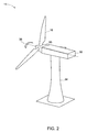
- FIG. 2 illustrates a wind turbine 14, wherein aspects of the present technique can be incorporated.
- the wind turbine 14 comprises a rotor 30 having multiple blades 16 extending therefrom.
- the wind turbine 14 also comprises a nacelle 32 that is mounted atop a tower 34.
- the rotor 30 is drivingly coupled to an electrical generator (not shown) housed within the nacelle 32.
- the tower 34 exposes the blades 16 to the wind, and the blades 16 capture wind energy and transform the same into a rotational motion of the rotor 30 about an axis 36. This rotational motion is further converted into electrical energy by the electrical generator.
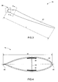
- the efficiency of wind energy capture by the blades 16 is proportional, among other factors, to the length L of the blade 16 (see FIG. 3). In order to establish structural rigidity for blades having large lengths, it is desirable to provide a higher width of the max chord W of the blade (see FIG. 4).
- the blade 16 manufactured in accordance with the present technique may have a length L and width W such that length and width of the blade and that of the transport carrier exceeds the allowed transportation limits set by the local authorities. This allows maximum wind energy capture and hence power efficiency of the wind turbine 14.
- transportation limits vary with geographical locations and are governed by regulations of the particular jurisdiction.
- FIG. 4 is a cross-sectional view of the blade 16 along the section 4-4 in FIG. 3.
- the blade 16 includes an outer skin 42 formed in the shape of an airfoil section having a leading edge 44 and a trailing edge 46.
- the distance W between the leading edge 44 and the trailing edge 46 is referred to as the chord width of the blade 16.
- the chord width varies along the length of the blade 16.
- the skin 42 may be formed of lightweight core material, such as foam and balsa wood.
- the skin 42 is manufactured in the secondary manufacturing facility 24 via low cost vacuum assisted resin transfer molding (VARTM) techniques.
- VARTM vacuum assisted resin transfer molding
- the blade 16 also includes longitudinal bending load bearing structures 48 and 50, also known in the pertinent art as "spar caps".
- the spar caps 48 and 50 are formed from continuous fiber reinforced composites such as carbon composites.
- the spar caps 48 and 50 may be formed of fiberglass or other continuous fibers. Spar caps may be manufactured, for example, by an automated fiber replacement method.
- One or more longitudinal crossbeams 52 also referred to as shear webs, are disposed within the airfoil section between the spar caps 48 and 50.
- the crossbeam 52 is adapted to withstand aerodynamic shear loading on the wind turbine blade 16.
- primary components refer to primary structural or aerodynamic load bearing members of the wind turbine blade, such as the root portion and the spar caps.
- the skin, shear web and bonding caps (not shown) exemplify secondary structural components of the blade. Secondary components may also bear aerodynamic loads. However, such loads are significantly smaller than those borne by the primary components
- the primary manufacturing facility 22 includes automated fabrication capability as well as non-destructive inspection capability. This facilitates quality and reliability in the primary parts and eliminates low cost testing processes at on site manufacturing facilities, which may compromise the quality of the composite blade structure.
- the primary manufacturing facilities may include testing apparatus, facilitating quality testing of primary structural components for various wind farms at a central location. These smaller structural components can be more efficiently packed on trucks or railcars and shipped to an assembly site close to the wind farm 12. Indeed, the structural integrity and quality of these primary components is of concern, as they are load bearing support structure.
- the max chord width may vary from about 3.6 meters for a blade of length 50 meters to about 8 meters for a blade of length 100 meters, utilized, for example, in offshore applications.
- the present technique allows smaller structural components to be transported from these quality-manufacturing sites to the wind farm location via roadways, waterways or rail.
- the quality manufacturing site may accordingly have access to a waterway or a rail depot.
- the primary and secondary components are assembled near the wind farm location to form the complete blade.
- size constraints of the blade due to infrastructure limitations can be mitigated. For example, it is much easier to transport a 50-meter long blade span via a waterway or over a short distances, than it is to transport the same blade from the centralized and more distant primary facility via roadways.
- the above-described techniques provide higher performance and more consistent quality in the primary structural blade components for improved reliability and lower weight designs.
- the techniques thus obviate restrictions on optimal airfoil design for most aerodynamic design.
Landscapes
- Engineering & Computer Science (AREA)
- Life Sciences & Earth Sciences (AREA)
- Sustainable Development (AREA)
- Sustainable Energy (AREA)
- Chemical & Material Sciences (AREA)
- Combustion & Propulsion (AREA)
- Mechanical Engineering (AREA)
- General Engineering & Computer Science (AREA)
- Wind Motors (AREA)
Abstract
Description
- The present invention relates generally to wind turbines and particularly to wind turbine blades. Specific embodiments of the present invention provide systems and methods for constructing a multi-piece large wind turbine blade for optimized quality and transportation, for example.
- Wind turbines are generally regarded as an environmentally safe and desirable source of energy. In summary, wind turbines harness the kinetic energy of wind and transform this kinetic energy into electrical energy. Thus, electrical power can be generated in an almost pollution free manner. Often, to maximize the efficacy of power generation and to simplify connection to a power grid, wind turbines are located in proximity to one another in what are generally referred to in the pertinent art as "wind farms." Advantageously, these wind farms are located in regions having relatively strong winds, such as offshore locations and flat plains, for instance.
- To generate electrical power, wind turbines generally include a rotor that supports a number of blades extending radially therefrom. These blades capture the kinetic energy of the wind and, in turn, cause rotational motion of a drive shaft and a rotor of a generator. The electromagnetic relationships between the rotor and the remaining components of the generator facilitate the translation of the kinetic energy of the rotor into electrical energy. In summary, rotation of the rotor induces electrical current in the generator, generating electrical power.
- The amount of energy produced by such wind power generation systems is dependent on the ability of the wind turbine to capture wind. As one example, the greater the efficacy of the wind turbine blades the greater the electrical power generated by a given turbine. In designing blades for a wind turbine, it has been found that increasing the length of the turbine blades can increase the power output of the wind turbine.
- However, blade designs is presently limited by infrastructure concerns. For example, the maximum length of blades for land-based wind farms is often limited by the size of transportation arteries, such as roads and bridges, because of the difficulty, if not inability, in transporting blades from the production facility to the wind farm. As a particular example, the maximum chord width allowed for transportation of blades through tunnels and under bridges may be limited by the design of such structures. Hence, it may be necessary to reduce the max chord from an optimal length, to meet these transportation and infrastructure requirements.
- Furthermore, it is generally desirable to maintain good quality control standards over wind turbine design, particularly when blade lengths are increased. Unfortunately, traditional techniques of fabricating entire wind blades at a single facility may require certain components of the blades to be manufactured at locations local to the wind farm for blade designs that exceed the transportation limits. However, it is typically more difficult for a manufacturer to invest in the infrastructure (e.g. non-destructive inspection equipment, automated manufacturing equipment, etc.) necessary for optimal quality control at such on-site production facilities where only a limited number of blades will be produced.
- Accordingly, there exists a need for manufacturing methods and systems to improve quality fabrications as well as transportation requirements of large wind turbine blades.
- The present invention accordingly provides a novel approach toward manufacturing a wind turbine blade that obviates the problems discussed above. Briefly, in accordance with one aspect of the present invention, a method of manufacturing a wind turbine blade for installation at a wind farm location includes manufacturing at least one structural component of the wind turbine blade at a first manufacturing facility and manufacturing a skin component of the wind turbine blade at a second manufacturing facility, wherein the second manufacturing facility is closer to the wind farm location than the first manufacturing facility. The method may further include providing the structural and skin components to an assembly location near the wind farm location.
- The invention will now be described in greater detail, by way of example, with reference to the drawings, in which:-
- FIG. 1 diagrammatically illustrates a geographic relationship of manufacturing facilities with respect to a wind farm, in accordance with one exemplary embodiment of the present technique;
- FIG. 2 illustrates a wind turbine assembly, in accordance with an exemplary embodiment of the present invention;
- FIG. 3 is a perspective view of a wind turbine blade assembly, in accordance with an exemplary embodiment of the present technique;
- FIG. 4 is a cross-sectional view of a wind turbine blade of the wind turbine of FIG. 3 along line 4-4; and
- FIG. 5 is a flowchart representative of a method of manufacturing a wind turbine blade, in accordance with an exemplary embodiment of the present technique.
- The present technique provides a method for constructing a multi-piece wind turbine blade for optimized quality and transportation. The technique involves fabrication of primary structural components of the wind turbine blade at quality suppliers and shipping smaller blade components rather than full blades over long distances for best balance of quality parts and optimal design. Certain embodiments of the present technique are discussed hereinafter with reference to FIGS. 1-6.
- FIG. 1 illustrates
geographic relationships 10 of various manufacturing facilities of wind blade components with respect to awind farm 12, in accordance with an exemplary embodiment of the present technique. Thewind farm 12 includes a plurality ofwind turbines 14, each wind turbine comprisingmultiple wind blades 16. Thewind turbines 14 at thewind farm 12 are operable to collectively supply electrical power to autility grid 18. Thewind farm 12 may be advantageously located in regions having relatively strong winds, such as offshore locations and flat plains, for instance. - The
wind blades 16 are constructed in multiple pieces at various manufacturing locations. These include a primarycomponent manufacturing facility 22 and one or more secondarycomponent manufacturing facilities 24. An exemplaryprimary manufacturing facility 22 includes a production site for producing the primary components of thewind blades 16, while thesecondary manufacturing facilities 24 include local production sites (i.e. relatively closer to the wind farm 12) for manufacturing secondary components of the wind blades. Primary and secondary components of the wind blades assemblies are discussed further below. Components manufactured infacilities wind farm location 12 viatransportation pathways transportation pathways transportation pathway 26 may also include bridges and tunnels. In one embodiment, primary and secondary components may be released to a freight transportation company to be shipped to thewind farm location 12. Components shipped from themanufacturing facilities wind farm location 12 and mounted on thewind turbines 14, as discussed below. In one embodiment, assembly of the wind blade components at the wind farm location is performed by the secondary manufacturer producing the secondary structural components. - In one embodiment, the
primary manufacturing facility 22 is a centralized production site that manufactures wind blade primary scomponents for a plurality of wind farms in various geographic locations. Theprimary manufacturing facility 22 may include automated manufacturing, in-house inspection, and testing facilities, including, for example, both destructive testing facilities and non-destructive testing facilities, such as ultra-sound testing facilities. Manufacturing smaller structural components in a centralized production site facilitates easier transportation of these primary structural components to the geographically spaced apart wind farms, while ensuring structural quality and integrity of these components. In certain embodiments, the primary and/or secondary manufacturing facilities may include contracting manufacturers, in which case the wind blade turbine manufacturer is not required to deal with the expense of such manufacturing facilities once the wind farm has been built. - FIG. 2 illustrates a
wind turbine 14, wherein aspects of the present technique can be incorporated. Thewind turbine 14 comprises arotor 30 havingmultiple blades 16 extending therefrom. Thewind turbine 14 also comprises anacelle 32 that is mounted atop atower 34. Therotor 30 is drivingly coupled to an electrical generator (not shown) housed within thenacelle 32. Thetower 34 exposes theblades 16 to the wind, and theblades 16 capture wind energy and transform the same into a rotational motion of therotor 30 about anaxis 36. This rotational motion is further converted into electrical energy by the electrical generator. As discussed earlier, the efficiency of wind energy capture by theblades 16 is proportional, among other factors, to the length L of the blade 16 (see FIG. 3). In order to establish structural rigidity for blades having large lengths, it is desirable to provide a higher width of the max chord W of the blade (see FIG. 4). - FIGS. 3 and 4 and illustrate various components of a
wind turbine blade 16 manufactured by the present technique. FIG. 3 is a perspective view of theblade 16 illustrating aroot portion 38 and abody 40 of theblade 16. Theroot portion 38 is a cylindrical section having a generally circular cross-section, and is a primary bending load bearing structure of theblade 16. In one embodiment, the root portion is generally manufactured at theprimary manufacturing facility 22 by an automated process, such as, for example by filament winding, tape winding, braiding, infusion, or automated fiber/tow/tape placement. Thebody 40 has an airfoil cross-section as best illustrated in FIG. 4. Theblade 16 manufactured in accordance with the present technique may have a length L and width W such that length and width of the blade and that of the transport carrier exceeds the allowed transportation limits set by the local authorities. This allows maximum wind energy capture and hence power efficiency of thewind turbine 14. Of course, as will be appreciated by one skilled in the art, transportation limits vary with geographical locations and are governed by regulations of the particular jurisdiction. - FIG. 4 is a cross-sectional view of the
blade 16 along the section 4-4 in FIG. 3. Theblade 16 includes anouter skin 42 formed in the shape of an airfoil section having a leadingedge 44 and a trailingedge 46. The distance W between theleading edge 44 and the trailingedge 46 is referred to as the chord width of theblade 16. The chord width varies along the length of theblade 16. However, it is believed that the maximum length of theblade 16 is at least partially defined by the maximum chord width W of theblade 16. Theskin 42 may be formed of lightweight core material, such as foam and balsa wood. In one embodiment, theskin 42 is manufactured in thesecondary manufacturing facility 24 via low cost vacuum assisted resin transfer molding (VARTM) techniques. Theblade 16 also includes longitudinal bendingload bearing structures longitudinal crossbeams 52, also referred to as shear webs, are disposed within the airfoil section between the spar caps 48 and 50. Thecrossbeam 52 is adapted to withstand aerodynamic shear loading on thewind turbine blade 16. In the exemplary embodiment, primary components refer to primary structural or aerodynamic load bearing members of the wind turbine blade, such as the root portion and the spar caps. The skin, shear web and bonding caps (not shown) exemplify secondary structural components of the blade. Secondary components may also bear aerodynamic loads. However, such loads are significantly smaller than those borne by the primary components - In accordance with embodiments of the present technique, smaller primary components of a wind blade, such as the root and spar caps, are fabricated at the
primary manufacturing facility 22. In one embodiment, theprimary manufacturing facility 22 includes automated fabrication capability as well as non-destructive inspection capability. This facilitates quality and reliability in the primary parts and eliminates low cost testing processes at on site manufacturing facilities, which may compromise the quality of the composite blade structure. Moreover the primary manufacturing facilities may include testing apparatus, facilitating quality testing of primary structural components for various wind farms at a central location. These smaller structural components can be more efficiently packed on trucks or railcars and shipped to an assembly site close to thewind farm 12. Indeed, the structural integrity and quality of these primary components is of concern, as they are load bearing support structure. At the assembly site close to thewind farm 12, lower cost processes can be used to form the large secondary structures. These include vacuum assisted infusion or wet lamination processes on theskin 42 and shear webs to form the airfoil.. Theshear web 52 may then disposed between the spar caps 48 and 50 and bonded to the skin and spar caps. Shipping the smaller components enables more efficient transportation, especially via bridges and through tunnels and under bridges, which had traditionally restricted the maximum permissible dimensions (W and L) of the wind turbine blades. The present technique obviates the above problem by forming the largest component of theblade 16, i.e. theskin 42 near the wind farms, vitiating the restrictions on max chord to enable optimized airfoil design. Using the presently described on site assembly technique, it may be possible to achieve unlimited blade length and max chord width. For example, the max chord width may vary from about 3.6 meters for a blade oflength 50 meters to about 8 meters for a blade of length 100 meters, utilized, for example, in offshore applications. - Keeping FIGS. 1-4 in mind, FIG. 5 is a flow chart illustrating an
exemplary method 54 for manufacturing a wind turbine blade according to one embodiment of the present technique. Themethod 54 includes manufacturing the primary components of the blade, such as the root and the spar caps, for example, at a primary manufacturing site (block 56). As discussed above, this site may incorporate automated manufacturing systems and in house inspection techniques. Atblock 58, the secondary components are manufactured at one or more regional low cost manufacturing sites. Secondary components may include, for instance, the skin and the shear web. As these components are less critical structures , structural integrity is a lesser concern in comparison to the primary components of the blade. The primary and secondary components are then shipped atblock 60 to an assembly site near the wind farm, for instance, by a freight carrier. As discussed, the present technique allows smaller structural components to be transported from these quality-manufacturing sites to the wind farm location via roadways, waterways or rail. The quality manufacturing site may accordingly have access to a waterway or a rail depot. Finally, atstep 62, the primary and secondary components are assembled near the wind farm location to form the complete blade. By manufacturing the larger secondary components, such as the skin, at a facility more proximate to the wind farm, size constraints of the blade due to infrastructure limitations can be mitigated. For example, it is much easier to transport a 50-meter long blade span via a waterway or over a short distances, than it is to transport the same blade from the centralized and more distant primary facility via roadways. - As can be appreciated, the above-described techniques provide higher performance and more consistent quality in the primary structural blade components for improved reliability and lower weight designs. The techniques thus obviate restrictions on optimal airfoil design for most aerodynamic design.
Claims (10)
- A method for manufacturing a wind turbine blade (16) for installation at a wind farm location (10), comprising:manufacturing at least one structural component of the wind turbine blade (16) at a first manufacturing facility (22); andmanufacturing a skin component (42) of the wind turbine blade (16) at a second manufacturing facility (24), wherein the second manufacturing facility (24) is closer to the wind farm location (10) than the first manufacturing facility (22).
- The method of claim 1, further comprising providing the structural and skin components (42)to an assembly location proximate to the wind farm location (10).
- The method of claim 2, wherein providing the structural and skin components (42) comprises transporting the at least one structural component from the first manufacturing facility (22) to the assembly location.
- The method of claim 1, further comprising assembling the structural and skin components(42) at the wind farm location (10).
- The method of claim 2, wherein providing the structural and skin components (42) comprises releasing the structural and skin component (42)s to a freight transportation company for delivery.
- The method of claim 1 wherein the at least one structural component comprises a spar cap (48, 50).
- The method of claim 1 wherein the at least one structural component comprises a root portion (38) of the wind turbine blade (16).
- The method of claim 1, further comprising manufacturing a shear web (52) of the wind turbine blade (16) at the secondary manufacturing facility.
- The method of claim 6, comprising forming the spar caps (48, 50) via automated fiber replacement process.
- The method of claim 7, comprising forming the root portion (38) via an automated process, comprising tape winding, or fiber placement, or tape placement, or tow placement, or braiding, or infusion, or filament winding, or combinations thereof.
Applications Claiming Priority (1)
| Application Number | Priority Date | Filing Date | Title |
|---|---|---|---|
| US11/094,952 US20060225278A1 (en) | 2005-03-31 | 2005-03-31 | Wind blade construction and system and method thereof |
Publications (2)
| Publication Number | Publication Date |
|---|---|
| EP1707805A2 true EP1707805A2 (en) | 2006-10-04 |
| EP1707805A3 EP1707805A3 (en) | 2012-08-29 |
Family
ID=36228718
Family Applications (1)
| Application Number | Title | Priority Date | Filing Date |
|---|---|---|---|
| EP06251561A Withdrawn EP1707805A3 (en) | 2005-03-31 | 2006-03-23 | Wind blade construction and system and method thereof |
Country Status (5)
| Country | Link |
|---|---|
| US (1) | US20060225278A1 (en) |
| EP (1) | EP1707805A3 (en) |
| CN (1) | CN1840899B (en) |
| BR (1) | BRPI0601205A (en) |
| MX (1) | MXPA06003559A (en) |
Cited By (8)
| Publication number | Priority date | Publication date | Assignee | Title |
|---|---|---|---|---|
| CN101749174A (en) * | 2008-12-11 | 2010-06-23 | 通用电气公司 | Sparcap for wind turbine rotor blade and method of fabricating wind turbine rotor blade |
| US8250761B2 (en) | 2010-12-13 | 2012-08-28 | General Electric Company | Methods of manufacturing rotor blades for a wind turbine |
| WO2012130339A2 (en) | 2011-03-25 | 2012-10-04 | Siemens Aktiengesellschaft | Facility and method for manufacturing a rotor blade of a wind turbine and method for setting up the facility |
| US8360733B2 (en) | 2011-09-09 | 2013-01-29 | General Electric Company | Rotor blade for a wind turbine and methods of manufacturing the same |
| US8382440B2 (en) | 2008-12-05 | 2013-02-26 | Modular Wind Energy, Inc. | Efficient wind turbine blades, wind turbine blade structures, and associated systems and methods of manufacture, assembly and use |
| CN101463794B (en) * | 2007-12-19 | 2013-03-27 | 通用电气公司 | Multi-segment wind turbine blade and method for assembling the same |
| US9574544B2 (en) | 2013-12-16 | 2017-02-21 | General Electric Company | Methods of manufacturing rotor blade components for a wind turbine |
| US9709030B2 (en) | 2013-12-16 | 2017-07-18 | General Electric Company | Methods of manufacturing rotor blade components for a wind turbine |
Families Citing this family (36)
| Publication number | Priority date | Publication date | Assignee | Title |
|---|---|---|---|---|
| US7517198B2 (en) * | 2006-03-20 | 2009-04-14 | Modular Wind Energy, Inc. | Lightweight composite truss wind turbine blade |
| US7908923B2 (en) * | 2006-12-07 | 2011-03-22 | Siemens Aktiengesellschaft | Method of non-destructively testing a work piece and non-destructive testing arrangement |
| US7608939B2 (en) * | 2007-01-04 | 2009-10-27 | General Electric Company | Methods and apparatus for assembling and operating monocoque rotary machines |
| US7976282B2 (en) * | 2007-01-26 | 2011-07-12 | General Electric Company | Preform spar cap for a wind turbine rotor blade |
| US7895745B2 (en) * | 2007-03-09 | 2011-03-01 | General Electric Company | Method for fabricating elongated airfoils for wind turbines |
| ES2319152B1 (en) * | 2007-07-17 | 2010-01-11 | Fco.Javier Garcia Castro | PROCEDURE FOR THE MANUFACTURE OF WIND SHOES. |
| US8733549B2 (en) | 2007-11-13 | 2014-05-27 | General Electric Company | System for containing and/or transporting wind turbine components |
| US20090146433A1 (en) * | 2007-12-07 | 2009-06-11 | General Electric Company | Method and apparatus for fabricating wind turbine components |
| US7740453B2 (en) * | 2007-12-19 | 2010-06-22 | General Electric Company | Multi-segment wind turbine blade and method for assembling the same |
| US7841835B2 (en) * | 2009-02-20 | 2010-11-30 | General Electric Company | Spar cap for wind turbine blades |
| US8753091B1 (en) | 2009-05-20 | 2014-06-17 | A&P Technology, Inc. | Composite wind turbine blade and method for manufacturing same |
| US7998303B2 (en) * | 2009-05-28 | 2011-08-16 | General Electric Company | Method for assembling jointed wind turbine blade |
| ES2423186T3 (en) * | 2009-08-20 | 2013-09-18 | Siemens Aktiengesellschaft | Fiber reinforced plastic structure and method to produce fiber reinforced plastic structure |
| US20120159785A1 (en) * | 2009-09-04 | 2012-06-28 | BayerMaerialScience LLC | Automated processes for the production of polyurethane wind turbine blades |
| US8702397B2 (en) * | 2009-12-01 | 2014-04-22 | General Electric Company | Systems and methods of assembling a rotor blade for use in a wind turbine |
| US8142164B2 (en) * | 2009-12-31 | 2012-03-27 | General Electric Company | Rotor blade for use with a wind turbine and method for assembling rotor blade |
| US10137542B2 (en) | 2010-01-14 | 2018-11-27 | Senvion Gmbh | Wind turbine rotor blade components and machine for making same |
| EP2524134B1 (en) | 2010-01-14 | 2014-05-07 | Neptco, Inc. | Wind turbine rotor blade components and methods of making same |
| US8192169B2 (en) * | 2010-04-09 | 2012-06-05 | Frederick W Piasecki | Highly reliable, low cost wind turbine rotor blade |
| US9500179B2 (en) | 2010-05-24 | 2016-11-22 | Vestas Wind Systems A/S | Segmented wind turbine blades with truss connection regions, and associated systems and methods |
| DE102010042530B4 (en) * | 2010-10-15 | 2015-04-30 | Senvion Se | Bulkhead of a wind turbine |
| US8900671B2 (en) | 2011-02-28 | 2014-12-02 | General Electric Company | Method for manufacture of an infused spar cap using a low viscosity matrix material |
| US8262362B2 (en) * | 2011-06-08 | 2012-09-11 | General Electric Company | Wind turbine blade shear web with spring flanges |
| US8393871B2 (en) | 2011-07-19 | 2013-03-12 | General Electric Company | Wind turbine blade shear web connection assembly |
| US8257048B2 (en) | 2011-07-19 | 2012-09-04 | General Electric Company | Wind turbine blade multi-component shear web with intermediate connection assembly |
| US8235671B2 (en) | 2011-07-19 | 2012-08-07 | General Electric Company | Wind turbine blade shear web connection assembly |
| WO2013086667A1 (en) * | 2011-12-12 | 2013-06-20 | General Electric Company | Wind turbine blade shear web connection assembly |
| US20140064980A1 (en) * | 2012-08-30 | 2014-03-06 | General Electric Company | Rotor blades with infused prefabricated shear webs and methods for making the same |
| GB2520007A (en) * | 2013-11-05 | 2015-05-13 | Vestas Wind Sys As | Improvements relating to wind turbine rotor blades |
| US9745954B2 (en) | 2014-04-30 | 2017-08-29 | General Electric Company | Rotor blade joint assembly with multi-component shear web |
| US20160377052A1 (en) * | 2015-06-29 | 2016-12-29 | General Electric Company | Blade root section for a modular rotor blade and method of manufacturing same |
| US10519927B2 (en) | 2017-02-20 | 2019-12-31 | General Electric Company | Shear web for a wind turbine rotor blade |
| US10987879B2 (en) * | 2017-03-02 | 2021-04-27 | General Electric Company | Methods of manufacturing rotor blade components for a wind turbine |
| US10570879B2 (en) | 2017-05-23 | 2020-02-25 | General Electric Company | Joint assembly for a wind turbine rotor blade with flanged bushings |
| US10563636B2 (en) | 2017-08-07 | 2020-02-18 | General Electric Company | Joint assembly for a wind turbine rotor blade |
| WO2021026198A1 (en) * | 2019-08-05 | 2021-02-11 | Georgia Tech Research Corporation | Systems and methods for repurposing retired wind turbines as electric utility line poles |
Citations (1)
| Publication number | Priority date | Publication date | Assignee | Title |
|---|---|---|---|---|
| US4732542A (en) * | 1981-04-01 | 1988-03-22 | Messerschmitt-Bolkow-Blohm Gesellschaft mit beschranker Haftung | Large airfoil structure and method for its manufacture |
Family Cites Families (7)
| Publication number | Priority date | Publication date | Assignee | Title |
|---|---|---|---|---|
| US3606580A (en) * | 1969-09-10 | 1971-09-20 | Cyclops Corp | Hollow airfoil members |
| US5375324A (en) * | 1993-07-12 | 1994-12-27 | Flowind Corporation | Vertical axis wind turbine with pultruded blades |
| US5669758A (en) * | 1996-01-24 | 1997-09-23 | Williamson; Larry D. | Wind turbine |
| US20020148114A1 (en) * | 2001-03-02 | 2002-10-17 | Ruebusch Richard T. | Modular, vertically-integrated manufacturing method for a lawn and garden implement |
| DE10152557C1 (en) * | 2001-10-24 | 2003-06-18 | Aloys Wobben | Wind energy plant with busbars |
| DK175718B1 (en) * | 2002-04-15 | 2005-02-07 | Ssp Technology As | Möllevinge |
| US20050186081A1 (en) * | 2004-02-24 | 2005-08-25 | Mohamed Mansour H. | Wind blade spar cap and method of making |
-
2005
- 2005-03-31 US US11/094,952 patent/US20060225278A1/en not_active Abandoned
-
2006
- 2006-03-23 EP EP06251561A patent/EP1707805A3/en not_active Withdrawn
- 2006-03-30 MX MXPA06003559A patent/MXPA06003559A/en active IP Right Grant
- 2006-03-31 BR BRPI0601205-1A patent/BRPI0601205A/en not_active IP Right Cessation
- 2006-03-31 CN CN2006100719778A patent/CN1840899B/en not_active Expired - Fee Related
Patent Citations (1)
| Publication number | Priority date | Publication date | Assignee | Title |
|---|---|---|---|---|
| US4732542A (en) * | 1981-04-01 | 1988-03-22 | Messerschmitt-Bolkow-Blohm Gesellschaft mit beschranker Haftung | Large airfoil structure and method for its manufacture |
Non-Patent Citations (2)
| Title |
|---|
| ANONYMOUS: "Stringer, Korea Manufacturer", tradeKorea.com , 30 September 2002 (2002-09-30), XP002679081, Retrieved from the Internet: URL:http://www.tradekorea.com/product-detail/P00026144/Stringer.html [retrieved on 2012-07-02] * |
| Peter Pae: "A Plane as Big as the Globe: The A380, the largest airliner ever built, will be unveiled by Airbus on Tuesday. It's the sum of a worldwide ballet of parts manufacturers", LA Times 17 jan 2005 , 17 January 2005 (2005-01-17), XP002679080, Retrieved from the Internet: URL:http://www.mindfully.org/Technology/2005/A380-Largest-Airliner17jan05.htm [retrieved on 2012-07-02] * |
Cited By (16)
| Publication number | Priority date | Publication date | Assignee | Title |
|---|---|---|---|---|
| CN101463794B (en) * | 2007-12-19 | 2013-03-27 | 通用电气公司 | Multi-segment wind turbine blade and method for assembling the same |
| US8480370B2 (en) | 2008-12-05 | 2013-07-09 | Modular Wind Energy, Inc. | Efficient wind turbine blades, wind turbine blade structures, and associated systems and methods of manufacture, assembly and use |
| US8506258B2 (en) | 2008-12-05 | 2013-08-13 | Modular Wind Energy, Inc. | Efficient wind turbine blades, wind turbine blade structures, and associated systems and methods of manufacture, assembly and use |
| US9518558B2 (en) | 2008-12-05 | 2016-12-13 | Vestas Wind Systems A/S | Efficient wind turbine blades, wind turbine blade structures, and associated systems and methods of manufacture, assembly and use |
| US8382440B2 (en) | 2008-12-05 | 2013-02-26 | Modular Wind Energy, Inc. | Efficient wind turbine blades, wind turbine blade structures, and associated systems and methods of manufacture, assembly and use |
| US8500408B2 (en) | 2008-12-05 | 2013-08-06 | Modular Wind Energy, Inc. | Efficient wind turbine blades, wind turbine blade structures, and associated systems and methods of manufacture, assembly and use |
| US8475133B2 (en) | 2008-12-05 | 2013-07-02 | Modular Wind Energy, Inc. | Efficient wind turbine blades, wind turbine blade structures, and associated systems and methods of manufacture, assembly and use |
| US8500409B2 (en) | 2008-12-05 | 2013-08-06 | Modular Wind Energy, Inc. | Efficient wind turbine blades, wind turbine blade structures, and associated systems and methods of manufacture, assembly and use |
| CN101749174B (en) * | 2008-12-11 | 2013-04-17 | 通用电气公司 | Method of fabricating wind turbine rotor blade and sparcap for wind turbine rotor blade |
| CN101749174A (en) * | 2008-12-11 | 2010-06-23 | 通用电气公司 | Sparcap for wind turbine rotor blade and method of fabricating wind turbine rotor blade |
| US8250761B2 (en) | 2010-12-13 | 2012-08-28 | General Electric Company | Methods of manufacturing rotor blades for a wind turbine |
| WO2012130339A2 (en) | 2011-03-25 | 2012-10-04 | Siemens Aktiengesellschaft | Facility and method for manufacturing a rotor blade of a wind turbine and method for setting up the facility |
| US8753092B2 (en) | 2011-09-09 | 2014-06-17 | General Electric Company | Rotor blade for a wind turbine and methods of manufacturing the same |
| US8360733B2 (en) | 2011-09-09 | 2013-01-29 | General Electric Company | Rotor blade for a wind turbine and methods of manufacturing the same |
| US9574544B2 (en) | 2013-12-16 | 2017-02-21 | General Electric Company | Methods of manufacturing rotor blade components for a wind turbine |
| US9709030B2 (en) | 2013-12-16 | 2017-07-18 | General Electric Company | Methods of manufacturing rotor blade components for a wind turbine |
Also Published As
| Publication number | Publication date |
|---|---|
| BRPI0601205A (en) | 2006-12-19 |
| US20060225278A1 (en) | 2006-10-12 |
| CN1840899A (en) | 2006-10-04 |
| MXPA06003559A (en) | 2006-09-29 |
| EP1707805A3 (en) | 2012-08-29 |
| CN1840899B (en) | 2012-08-01 |
Similar Documents
| Publication | Publication Date | Title |
|---|---|---|
| EP1707805A2 (en) | Wind blade construction and system and method thereof | |
| CN1755102B (en) | Multi-piece wind turbine rotor blades and wind turbines incorporating same | |
| EP2134963B1 (en) | Method of fabricating a wind turbine blade assembly | |
| US7997874B2 (en) | Wind turbine rotor blade joint | |
| US9719489B2 (en) | Wind turbine rotor blade assembly having reinforcement assembly | |
| EP2881580B1 (en) | Spar assembly for a wind turbine rotor blade | |
| US8360732B2 (en) | Rotor blade section and method for assembling a rotor blade for a wind turbine | |
| US10570879B2 (en) | Joint assembly for a wind turbine rotor blade with flanged bushings | |
| EP2466135A2 (en) | Reinforcement system for wind turbine tower | |
| Ragheb | Modern wind generators | |
| JP2005147086A (en) | Blade of horizontal axis wind mill | |
| CN112469894A (en) | Modular wind turbine blade | |
| CN201474874U (en) | Detachable lifting wind-driven generator tower frame | |
| CN207715302U (en) | A kind of ring-like gantry system of wind power generation | |
| Divone | Evolution of modern wind turbines part A: 1940 to 1994 | |
| Willey | Design and development of megawatt wind turbines | |
| Ritschel et al. | Designing Wind Turbines: Engineering and Manufacturing Process in the Industrial Context | |
| CN117813448A (en) | Shear web for wind turbine blade and method of making the same | |
| Ritschel et al. | Designing Wind Turbines |
Legal Events
| Date | Code | Title | Description |
|---|---|---|---|
| PUAI | Public reference made under article 153(3) epc to a published international application that has entered the european phase |
Free format text: ORIGINAL CODE: 0009012 |
|
| AK | Designated contracting states |
Kind code of ref document: A2 Designated state(s): AT BE BG CH CY CZ DE DK EE ES FI FR GB GR HU IE IS IT LI LT LU LV MC NL PL PT RO SE SI SK TR |
|
| AX | Request for extension of the european patent |
Extension state: AL BA HR MK YU |
|
| PUAL | Search report despatched |
Free format text: ORIGINAL CODE: 0009013 |
|
| RIC1 | Information provided on ipc code assigned before grant |
Ipc: F03D 1/00 20060101AFI20120704BHEP |
|
| RIC1 | Information provided on ipc code assigned before grant |
Ipc: F03D 1/00 20060101AFI20120719BHEP |
|
| AK | Designated contracting states |
Kind code of ref document: A3 Designated state(s): AT BE BG CH CY CZ DE DK EE ES FI FR GB GR HU IE IS IT LI LT LU LV MC NL PL PT RO SE SI SK TR |
|
| AX | Request for extension of the european patent |
Extension state: AL BA HR MK YU |
|
| 17P | Request for examination filed |
Effective date: 20130228 |
|
| AKX | Designation fees paid |
Designated state(s): DE DK ES GB NL |
|
| STAA | Information on the status of an ep patent application or granted ep patent |
Free format text: STATUS: THE APPLICATION IS DEEMED TO BE WITHDRAWN |
|
| 18D | Application deemed to be withdrawn |
Effective date: 20130302 |
|
| P01 | Opt-out of the competence of the unified patent court (upc) registered |
Effective date: 20230522 |