EP1707771A2 - Mounting structure for oil pan - Google Patents
Mounting structure for oil pan Download PDFInfo
- Publication number
- EP1707771A2 EP1707771A2 EP05011741A EP05011741A EP1707771A2 EP 1707771 A2 EP1707771 A2 EP 1707771A2 EP 05011741 A EP05011741 A EP 05011741A EP 05011741 A EP05011741 A EP 05011741A EP 1707771 A2 EP1707771 A2 EP 1707771A2
- Authority
- EP
- European Patent Office
- Prior art keywords
- pan
- engine
- flange
- oil
- mounting structure
- Prior art date
- Legal status (The legal status is an assumption and is not a legal conclusion. Google has not performed a legal analysis and makes no representation as to the accuracy of the status listed.)
- Granted
Links
- 230000002093 peripheral effect Effects 0.000 claims abstract description 24
- 230000004308 accommodation Effects 0.000 claims abstract description 16
- 239000002184 metal Substances 0.000 claims abstract description 7
- 229910052751 metal Inorganic materials 0.000 claims abstract description 7
- 229920003002 synthetic resin Polymers 0.000 claims abstract description 7
- 239000000057 synthetic resin Substances 0.000 claims abstract description 7
- 239000003921 oil Substances 0.000 description 47
- 238000007789 sealing Methods 0.000 description 4
- 238000010276 construction Methods 0.000 description 3
- 238000005336 cracking Methods 0.000 description 3
- 239000004677 Nylon Substances 0.000 description 2
- 238000005452 bending Methods 0.000 description 2
- 210000000078 claw Anatomy 0.000 description 2
- 230000001050 lubricating effect Effects 0.000 description 2
- 229920001778 nylon Polymers 0.000 description 2
- 101100522299 Escherichia coli (strain K12) agaW gene Proteins 0.000 description 1
- 238000001816 cooling Methods 0.000 description 1
- 230000000694 effects Effects 0.000 description 1
- 150000002739 metals Chemical class 0.000 description 1
- 239000010705 motor oil Substances 0.000 description 1
Images


Classifications
-
- F—MECHANICAL ENGINEERING; LIGHTING; HEATING; WEAPONS; BLASTING
- F01—MACHINES OR ENGINES IN GENERAL; ENGINE PLANTS IN GENERAL; STEAM ENGINES
- F01M—LUBRICATING OF MACHINES OR ENGINES IN GENERAL; LUBRICATING INTERNAL COMBUSTION ENGINES; CRANKCASE VENTILATING
- F01M11/00—Component parts, details or accessories, not provided for in, or of interest apart from, groups F01M1/00 - F01M9/00
- F01M11/0004—Oilsumps
-
- F—MECHANICAL ENGINEERING; LIGHTING; HEATING; WEAPONS; BLASTING
- F01—MACHINES OR ENGINES IN GENERAL; ENGINE PLANTS IN GENERAL; STEAM ENGINES
- F01M—LUBRICATING OF MACHINES OR ENGINES IN GENERAL; LUBRICATING INTERNAL COMBUSTION ENGINES; CRANKCASE VENTILATING
- F01M11/00—Component parts, details or accessories, not provided for in, or of interest apart from, groups F01M1/00 - F01M9/00
- F01M11/0004—Oilsumps
- F01M2011/0054—Fastening to the cylinder block
-
- F—MECHANICAL ENGINEERING; LIGHTING; HEATING; WEAPONS; BLASTING
- F01—MACHINES OR ENGINES IN GENERAL; ENGINE PLANTS IN GENERAL; STEAM ENGINES
- F01M—LUBRICATING OF MACHINES OR ENGINES IN GENERAL; LUBRICATING INTERNAL COMBUSTION ENGINES; CRANKCASE VENTILATING
- F01M11/00—Component parts, details or accessories, not provided for in, or of interest apart from, groups F01M1/00 - F01M9/00
- F01M11/0004—Oilsumps
- F01M2011/0087—Sump being made of different parts
-
- F—MECHANICAL ENGINEERING; LIGHTING; HEATING; WEAPONS; BLASTING
- F01—MACHINES OR ENGINES IN GENERAL; ENGINE PLANTS IN GENERAL; STEAM ENGINES
- F01M—LUBRICATING OF MACHINES OR ENGINES IN GENERAL; LUBRICATING INTERNAL COMBUSTION ENGINES; CRANKCASE VENTILATING
- F01M11/00—Component parts, details or accessories, not provided for in, or of interest apart from, groups F01M1/00 - F01M9/00
- F01M11/0004—Oilsumps
- F01M2011/0091—Oilsumps characterised by used materials
Definitions
- This invention relates to a mounting structure for an oil pan comprising an outer pan made from a metal and an inner pan made from a synthetic resin and bolted to the underside of an engine.
- an inner pan is bolted to an inner surface of an outer pan (see JP-A-2005-9418 , for example) or the inner pan has a flange held between the outer pan and an engine and fastened by bolts ( JP-A-2003-222012 , for example).
- the inner pan which is made from a synthetic resin, has a thermal deformation ratio different from those of the outer pan and engine, both of which are made from respective metals. Accordingly, an internal stress occurs in the inner pan with thermal deformation thereof, resulting in possibility of cracks produced in the inner pan. Furthermore, when held between the outer pan and the engine and fastened by bolts, the flange of the inner pan may creep such that the sealing performance would be reduced in the co-fastened portion.
- an object of the present invention is to provide a mounting structure for an oil pan which can prevent the inner pan from cracking and has a high sealing performance.
- the present invention provides a mounting structure for an oil pan including an outer pan made from a metal, an inner pan made from a synthetic resin and fixed to an underside of an engine by bolts and a flange protruding sideways from the inner pan, the outer pan having an upper opening edge, the engine having an underside with an opening edge, the mounting structure being characterized by abutments provided on outer peripheral portions of the opening edges of the outer pan and the engine so as to abut agaW st each other, respectively, bolt holes formed through the outer peripheral portions of the opening edges so that the bolts are inserted through the bolt holes respectively, and an accommodation space defined between inner peripheral portions of the opening edges of the outer pan and the engine by collapsing the inner peripheral portion of the opening edge of either outer pan or engine, and in that the flange is loosely fitted in the accommodation space.
- the flange of the inner pan is loosely fitted in the accommodation space defined between the inner peripheral portions of the opening edges of the outer pan and the engine.
- the inner pan is held by the outer pan and the engine while being allowed to be thermally deformed. Consequently, an internal stress due to thermal deformation is hard to occur in the inner pan, whereupon the inner pan can be prevented from cracking.
- the outer peripheral portions of the opening edges of the outer pan and the engine are in abutment with each other without the flange being held therebetween. Consequently, the sealing performance can be prevented from being reduced by creep deformation.
- the mounting structure further comprises rugged engagement portions provided in the opening edges of the outer pan or engine and the flange so as to be loosely fitted with each other vertically, respectively. Consequently, the flange can be prevented from falling off while being allowed to move in the accommodation space.
- the mounting structure further comprises inner pan retainers provided on the inner and outer pans so as to be engaged with each other, the inner pan retainers retaining the inner pan at a normal position where the inner pan is assembled to the outer pan.
- the inner pan retainers When the inner pan has been assembled to the normal position of the outer pan, the inner and outer pans are prevented from falling off by the inner pan retainers thereby to be integrated with each other. Consequently, the oil pan can be attached to and detached from the engine more efficiently.
- reference numeral 50 designates an engine having an underside with an opening edge 52.
- the opening edge 52 has a flange 53 protruding sideways.
- An oil pan 10 of the first embodiment is mounted on the opening edge 52 including the flange 53.
- the oil pan 10 includes an outer pan 11 and an inner pan 20 disposed in the outer pan 11.
- the outer pan 11 is made from a metal and formed into the shape of a container with an upper open end.
- the outer pan 11 has a flange 13 protruding sideways from an opening edge 12 thereof.
- the outer pan 11 includes a side wall 11S with a shelf 11T formed by bending a part thereof near the upper end into the shape of a crank. An interior of the outer pan 11 below the shelf 11T is narrower than an interior of the outer pan 11 over the shelf 11T.
- the outer pan 11 further includes a bottom 11U formed with a drain hole 11D.
- the drain hole 11D is formed so as to be located lowest when the oil pan 10 is assembled to the engine 50.
- a drain bolt 15 is inserted into the drain hole 11D from outside the outer pan 11. Oil reserved in the oil pan 10 flows out when the drain bolt 15 is detached out of the drain hole 11D.
- the inner pan 20 is made from a synthetic resin such as nylon and formed into the shape of a container with an upper open end.
- the inner pan 20 includes a side wall 20S with a shelf 20T formed by bending a part thereof near the upper end into the shape of a crank.
- An interior of the inner pan 20 below the shelf 20T is narrower than an interior of the inner pan 20 over the shelf 20T.
- the shelf 20T of the inner pan 20 is placed on an upper surface of the shelf 11T of the outer pan 11 so that the interior of the outer pan 11 below the shelves 11T and 20T is divided into an outer chamber 18 outside the inner pan 20 and an inner chamber 19 inside the inner pan 20.
- a suction pipe 31 extending downward from the engine 50 side has a distal end located in the inner chamber 19.
- a middle opening of the inner pan 20 surrounded by the shelf 20T is closed by a baffle plate 30.
- the suction pipe 31 extends through a hole (not shown) formed in the baffle plate 30.
- the baffle plate 30 has a plurality of locking claws 30T formed on an outer edge thereof. The locking claws 30T engage respective locking holes 20K formed through a part of the side wall located near the underside of the shelf 20T of the inner pan 20. As a result, the baffle plate 30 is held in a closing state, thereby limiting upward movement of the oil in the inner pan 20.
- the inner pan 20 has a plurality of lateral holes 23 formed through a part of the side wall 20S located below the shelf 20T. Oil is suitably circulated through the lateral holes 23 between the inner and outer chambers 19 and 18.
- the inner pan 20 further has a bottom 20U through which a drain hole 20D is formed. The drain hole 20D is closed by the drain bolt 15 inserted through the drain hole 11D of the outer pan 11.
- the inner pan 20 has a protruding wall or flange 25 protruding sideways from the upper end thereof.
- the flange 25 extends along an entire upper periphery of the inner pan 20, for example.
- the flange 25 is placed on an inner peripheral portion of flat upper surface of the opening edge 12.
- the flange 25 has a plurality of embossments 26. formed on an upper surface of the flange 25. Each embossment 26 is formed into a semispherical shape.
- the opening edge 12 of the outer pan 11 includes an outer portion spaced away from the flange 25.
- the outer peripheral portion of the opening edge 12 serves as an abutment 12T.
- the abutment 12 has a plurality of bolt holes 12B formed therethrough.
- the opening edge 52 of the engine 50 also includes an outer peripheral portion also serving as an abutment 52T.
- the abutment 52T has a plurality of female screw holes 52B formed therethrough.
- the bolt holes 12B and the female screw holes 52B constitute a bolt engagement hole.
- the opening edge 52 of the engine 50 includes an inner peripheral portion formed with a collapsed surface 54 collapsed from the outer peripheral portion into a stepped shape.
- Bolts B inserted through the bolt holes 12B of the outer pan 11 from below are brought into threading engagement with the female screw holes 52B of the engine 50 respectively.
- the outer peripheral portions of the opening edges 12 and 52 namely, the abutments 12T and 52T are abutted against each other, whereby the outer pan 11 is fixed to the engine 50, and an accommodation space 56 is defined between the collapsed surface 54 of the engine 50 and the inner peripheral portion of the opening edge 12 of the outer pan 11.
- the flange 25 of the inner pan 20 is loosely fitted in the accommodation space 56.
- the collapsed surface 54 is formed with a plurality of recesses 57 in which the embossments 26 of the flange 25 are loosely fitted.
- the aforesaid "loosely fitted” refers to a state where a component is fitted in another component with a gap therebetween. Accordingly, when a component is loosely fitted in another component, each component is movable in a range of the gap. More specifically, a gap is defined between the upper surface of the opening edge 12 of the outer pan 11 and the collapsed surface 54. The gap is slightly larger than a thickness of the flange 25 such that a gap 29A is defined between the collapsed surface 54 and the flange 25. Further, another gap 29B is defined between a stepped surface 55 of the engine opening edge 52 and an outer peripheral surface of the flange 25.
- a gap 29C is defined between an inner surface of the recess 57 and the embossment 26.
- a gap 28 is also defined between the part of the side wall 20S located over the shelf 20T of the inner pan 20 and the side wall 11S of the outer pan 11.
- the mounting structure operates as follows.
- the oil in the engine 50 is reserved in the oil pan 10 upon stop of the engine 50.
- the viscosity, thereof is increased and accordingly, the lubricating performance is lowered.
- the temperature of the oil is desired to rise as quickly as possible in starting an engine.
- the interior of the outer pan 11 is divided into the outer and inner chambers 18 and 19 by the inner pan 20 in the embodiment.
- the suction pipe 31 is disposed in the inner chamber 19. Accordingly, a higher priority is given to the oil in the inner chamber 19 when the oil is circulated into the engine 50.
- the temperature of the oil is increased more quickly in this case than in the case where all the oil in the oil pan 10 is circulated.
- the outer and inner chambers 18 and 19 communicate with each other via the small lateral holes 23 formed through the inner pan 20. Accordingly, the oil is restricted from flowing through the holes 23 into the inner chamber 19 when the viscosity of oil is high in the starting of the engine 50.
- the oil is subjected to heat such that the viscosity thereof is lowered, the oil flows from the outer chamber 18 into the inner chamber 19. More specifically, the oil is restricted from flowing from the outer chamber 18 into the inner chamber 19 immediately after starting of the engine 50, whereupon temperature rise of the oil is enhanced. Furthermore, after the oil temperature has been increased to a suitable value, the temperature of the oil in the inner chamber 19 is prevented from being excessively increased.
- the engine 50 and oil pan 10 repeat thermal deformation with temperature changes in the engine 50 and oil.
- Each of the outer pan 11 of the oil pan 10 and engine 50 is made from a metal whereas the inner pan 20 of the oil pan 10 is made from a synthetic resin.
- the inner pan 20 has a thermal deformation ratio differing from those of the outer pan 11 and engine 50. Accordingly, when the engine 50 starts and the temperature thereof is increased, the inner pan 20 shrinks or expands relative to the outer pan 11 and engine 50. More specifically, since the inner pan 20 is made from nylon in the embodiment, the inner pan shrinks about 0.85 mm per 100 mm when subjected to heat.
- the flange 25 of the inner pan 20 is loosely fitted in the accommodation space 56 defined between the opening edges 12 and 52 of the outer pan 11 and engine 50.
- the inner pan 20 is thus held by the outer pan 11 and the engine 50 while being allowed to be thermally deformed. Consequently, an internal stress due to thermal deformation is hard to occur in the inner pan 20, whereupon the inner pan 20 can be prevented from cracking.
- the outer peripheral portions of the opening edges 12 and 52 of the outer pan 11 and the engine 50 are in abutment with each other without the flange 25 being held therebetween. Consequently, the sealing performance can be prevented from being reduced by creep deformation.
- the embossments 26 are formed on the upper surface of the flange 25.
- the collapsed surface 54 of the engine 50 is formed with the recesses 57 in which the embossments 26 of the flange 25 are loosely fitted vertically. Consequently, the flange 25 can be prevented from falling off while being allowed to move in the accommodation space 56.
- the inner pan 20 can be rendered stable in the outer pan 11.
- the oil pan 10 since the entire oil pan 10 is fixed to the engine 50 using the bolts B, the oil pan 10 can be attached to and detached from the engine 50 more readily than the conventional construction in which the inner pan 20 is separately bolted to the outer pan 11.
- FIGS. 3 and 4 illustrate a second embodiment of the invention.
- the inner pan 20 has a locking arm 40 extending downward from a proximal end of the flange 25 in the second embodiment.
- the locking arm 40 has a locking protrusion 41 formed on a distal end thereof so as to extend toward the side wall 11S of the outer pan 11.
- the side wall 11S has a side-wall recess 42 formed so as to correspond to the locking protrusion 41.
- the construction of the oil pan of the second embodiment is the same as the first embodiment in the other respects. Accordingly, identical or similar parts in the second embodiment are labeled by the same reference symbols as in the first embodiment and the description of these parts will be eliminated.
- the inner pan 20 When the inner pan 20 has been assembled to the outer pan 11 so as to assume a normal position, the inner and outer pans 20 and 11 are prevented from falling off by the engagement of the locking protrusion 41 with the side-wall recess 42, thereby being integrated with each other. Consequently, the oil pan 10 can be attached to and detached from the engine 50 more efficiently.
- FIG. 5 illustrates a third embodiment of the invention.
- the flange 25 of the inner pan 20 has a locking wall 45 extending downward from the distal end thereof.
- the outer pan 11 has a collapsed surface 11V formed by collapsing the inner peripheral portion of the opening edge 12 into a stepped shape. Further, the collapsed surface 11V includes a locking groove 11W formed by collapsing the outer edge thereof.
- the opening edge 52 of the engine 50 includes a flat surface opposed to the opening edge 12 of the inner pan 20.
- the outer pan 11 has female screw holes 12C formed at the opening edge 12 side and the engine 50 has bolt holes 52C at the opening edge 52 side.
- the bolts B inserted through the bolt holes 12B of the outer pan 11 from above are brought into threading engagement with the female screw holes 12C of the outer pan 11 respectively.
- the construction of the oil pan of the third embodiment is the same as the first embodiment in the other respects. Accordingly, identical or similar parts in the third embodiment are labeled by the same reference symbols as in the first embodiment and the description of these parts will be eliminated.
- the bolt holes 52C and the female screw holes 12C constitute the bolt engagement holes.
- the accommodation space 56 is defined between the collapsed surface 11V of the opening edge 12 of the outer pan 11 and the inner peripheral portion of the opening edge 52 of the engine 50.
- the flange 25 of the inner pan 20 is loosely fitted in the accommodation space 56, and the locking wall 45 is also loosely fitted in the locking groove 11W. Consequently, the third embodiment can achieve the same effect as the first embodiment.
- the flange 25 is prevented from falling off in the accommodation space 56 by the engagement of the rugged engagement portions (the embossments 26 and recesses 57) in the first embodiment.
- the flange 25 may be prevented from falling off from the accommodation space 56 by limiting a moving range of the flange 25 by a rigidity of the inner pan 20 without provision of the rugged engagement portions.
- the flange 25 may protrude from an entire upper periphery of the inner pan 20 or from part of the upper periphery.
Landscapes
- Engineering & Computer Science (AREA)
- Mechanical Engineering (AREA)
- General Engineering & Computer Science (AREA)
- Lubrication Details And Ventilation Of Internal Combustion Engines (AREA)
- Cylinder Crankcases Of Internal Combustion Engines (AREA)
Abstract
Description
- This invention relates to a mounting structure for an oil pan comprising an outer pan made from a metal and an inner pan made from a synthetic resin and bolted to the underside of an engine.
- In conventional engine oil pans of the above-described type, an inner pan is bolted to an inner surface of an outer pan (see
JP-A-2005-9418 JP-A-2003-222012 - However, the inner pan, which is made from a synthetic resin, has a thermal deformation ratio different from those of the outer pan and engine, both of which are made from respective metals. Accordingly, an internal stress occurs in the inner pan with thermal deformation thereof, resulting in possibility of cracks produced in the inner pan. Furthermore, when held between the outer pan and the engine and fastened by bolts, the flange of the inner pan may creep such that the sealing performance would be reduced in the co-fastened portion.
- Therefore, an object of the present invention is to provide a mounting structure for an oil pan which can prevent the inner pan from cracking and has a high sealing performance.
- The present invention provides a mounting structure for an oil pan including an outer pan made from a metal, an inner pan made from a synthetic resin and fixed to an underside of an engine by bolts and a flange protruding sideways from the inner pan, the outer pan having an upper opening edge, the engine having an underside with an opening edge, the mounting structure being characterized by abutments provided on outer peripheral portions of the opening edges of the outer pan and the engine so as to abut agaW st each other, respectively, bolt holes formed through the outer peripheral portions of the opening edges so that the bolts are inserted through the bolt holes respectively, and an accommodation space defined between inner peripheral portions of the opening edges of the outer pan and the engine by collapsing the inner peripheral portion of the opening edge of either outer pan or engine, and in that the flange is loosely fitted in the accommodation space.
- The flange of the inner pan is loosely fitted in the accommodation space defined between the inner peripheral portions of the opening edges of the outer pan and the engine. The inner pan is held by the outer pan and the engine while being allowed to be thermally deformed. Consequently, an internal stress due to thermal deformation is hard to occur in the inner pan, whereupon the inner pan can be prevented from cracking. Furthermore, the outer peripheral portions of the opening edges of the outer pan and the engine are in abutment with each other without the flange being held therebetween. Consequently, the sealing performance can be prevented from being reduced by creep deformation.
- In one form of the invention, the mounting structure further comprises rugged engagement portions provided in the opening edges of the outer pan or engine and the flange so as to be loosely fitted with each other vertically, respectively. Consequently, the flange can be prevented from falling off while being allowed to move in the accommodation space.
- In another form of the invention, the mounting structure further comprises inner pan retainers provided on the inner and outer pans so as to be engaged with each other, the inner pan retainers retaining the inner pan at a normal position where the inner pan is assembled to the outer pan. When the inner pan has been assembled to the normal position of the outer pan, the inner and outer pans are prevented from falling off by the inner pan retainers thereby to be integrated with each other. Consequently, the oil pan can be attached to and detached from the engine more efficiently.
- The invention will be described, merely by way of example, with reference to the accompanying drawings, in which:
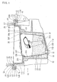
- FIG. 1 is a side section of an oil pan of one embodiment in accordance with the present invention;
- FIG. 2 is a partial side section of an engine and the oil pan;
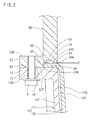
- FIG. 3 is a partial side section of the engine and the oil pan of a second embodiment in accordance with the present invention;
- FIG. 4 is a partial side section of the engine and the oil pan; and
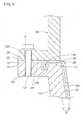
- FIG. 5 is a partial side section of the engine and the oil pan of a third embodiment in accordance with the present invention.
- A first embodiment of the present invention will be described with reference to FIGS. 1 and 2. Referring to FIG. 1,
reference numeral 50 designates an engine having an underside with anopening edge 52. Theopening edge 52 has aflange 53 protruding sideways. Anoil pan 10 of the first embodiment is mounted on theopening edge 52 including theflange 53. Theoil pan 10 includes anouter pan 11 and aninner pan 20 disposed in theouter pan 11. Theouter pan 11 is made from a metal and formed into the shape of a container with an upper open end. Theouter pan 11 has aflange 13 protruding sideways from anopening edge 12 thereof. - The
outer pan 11 includes aside wall 11S with ashelf 11T formed by bending a part thereof near the upper end into the shape of a crank. An interior of theouter pan 11 below theshelf 11T is narrower than an interior of theouter pan 11 over theshelf 11T. Theouter pan 11 further includes abottom 11U formed with adrain hole 11D. Thedrain hole 11D is formed so as to be located lowest when theoil pan 10 is assembled to theengine 50. Adrain bolt 15 is inserted into thedrain hole 11D from outside theouter pan 11. Oil reserved in theoil pan 10 flows out when thedrain bolt 15 is detached out of thedrain hole 11D. - The
inner pan 20 is made from a synthetic resin such as nylon and formed into the shape of a container with an upper open end. Theinner pan 20 includes aside wall 20S with ashelf 20T formed by bending a part thereof near the upper end into the shape of a crank. An interior of theinner pan 20 below theshelf 20T is narrower than an interior of theinner pan 20 over theshelf 20T. Theshelf 20T of theinner pan 20 is placed on an upper surface of theshelf 11T of theouter pan 11 so that the interior of theouter pan 11 below theshelves outer chamber 18 outside theinner pan 20 and aninner chamber 19 inside theinner pan 20. Asuction pipe 31 extending downward from theengine 50 side has a distal end located in theinner chamber 19. When an oil suction pump (not shown) is driven, oil in theinner chamber 19 is sucked into asuction port 31A of the lower end of thesuction pipe 31. The oil sucked into thesuction pipe 31 comes into contact with parts of theengine 50, lubricating and cooling the parts. Thereafter, the oil falls down from over theoil pan 10 to return into theinner chamber 19. - A middle opening of the
inner pan 20 surrounded by theshelf 20T is closed by abaffle plate 30. Thesuction pipe 31 extends through a hole (not shown) formed in thebaffle plate 30. Thebaffle plate 30 has a plurality oflocking claws 30T formed on an outer edge thereof. Thelocking claws 30T engagerespective locking holes 20K formed through a part of the side wall located near the underside of theshelf 20T of theinner pan 20. As a result, thebaffle plate 30 is held in a closing state, thereby limiting upward movement of the oil in theinner pan 20. - The
inner pan 20 has a plurality oflateral holes 23 formed through a part of theside wall 20S located below theshelf 20T. Oil is suitably circulated through thelateral holes 23 between the inner andouter chambers inner pan 20 further has a bottom 20U through which adrain hole 20D is formed. Thedrain hole 20D is closed by thedrain bolt 15 inserted through thedrain hole 11D of theouter pan 11. - The
inner pan 20 has a protruding wall orflange 25 protruding sideways from the upper end thereof. Theflange 25 extends along an entire upper periphery of theinner pan 20, for example. Theflange 25 is placed on an inner peripheral portion of flat upper surface of theopening edge 12. Theflange 25 has a plurality ofembossments 26. formed on an upper surface of theflange 25. Eachembossment 26 is formed into a semispherical shape. - The
opening edge 12 of theouter pan 11 includes an outer portion spaced away from theflange 25. The outer peripheral portion of theopening edge 12 serves as anabutment 12T. Theabutment 12 has a plurality ofbolt holes 12B formed therethrough. Theopening edge 52 of theengine 50 also includes an outer peripheral portion also serving as anabutment 52T. Theabutment 52T has a plurality offemale screw holes 52B formed therethrough. Thebolt holes 12B and thefemale screw holes 52B constitute a bolt engagement hole. - The opening
edge 52 of theengine 50 includes an inner peripheral portion formed with acollapsed surface 54 collapsed from the outer peripheral portion into a stepped shape. Bolts B inserted through the bolt holes 12B of theouter pan 11 from below are brought into threading engagement with the female screw holes 52B of theengine 50 respectively. As a result, the outer peripheral portions of the opening edges 12 and 52, namely, theabutments outer pan 11 is fixed to theengine 50, and anaccommodation space 56 is defined between thecollapsed surface 54 of theengine 50 and the inner peripheral portion of the openingedge 12 of theouter pan 11. Theflange 25 of theinner pan 20 is loosely fitted in theaccommodation space 56. Furthermore, thecollapsed surface 54 is formed with a plurality ofrecesses 57 in which theembossments 26 of theflange 25 are loosely fitted. - The aforesaid "loosely fitted" refers to a state where a component is fitted in another component with a gap therebetween. Accordingly, when a component is loosely fitted in another component, each component is movable in a range of the gap. More specifically, a gap is defined between the upper surface of the opening
edge 12 of theouter pan 11 and thecollapsed surface 54. The gap is slightly larger than a thickness of theflange 25 such that agap 29A is defined between thecollapsed surface 54 and theflange 25. Further, anothergap 29B is defined between a steppedsurface 55 of theengine opening edge 52 and an outer peripheral surface of theflange 25. Still further, agap 29C is defined between an inner surface of therecess 57 and theembossment 26. Furthermore, agap 28 is also defined between the part of theside wall 20S located over theshelf 20T of theinner pan 20 and theside wall 11S of theouter pan 11. - The mounting structure operates as follows. The oil in the
engine 50 is reserved in theoil pan 10 upon stop of theengine 50. In this case, when the oil is cooled, the viscosity, thereof is increased and accordingly, the lubricating performance is lowered. On the other hand, the temperature of the oil is desired to rise as quickly as possible in starting an engine. In view of this demand, the interior of theouter pan 11 is divided into the outer andinner chambers inner pan 20 in the embodiment. Thesuction pipe 31 is disposed in theinner chamber 19. Accordingly, a higher priority is given to the oil in theinner chamber 19 when the oil is circulated into theengine 50. As a result, in the starting of theengine 50, the temperature of the oil is increased more quickly in this case than in the case where all the oil in theoil pan 10 is circulated. Furthermore, the outer andinner chambers inner pan 20. Accordingly, the oil is restricted from flowing through theholes 23 into theinner chamber 19 when the viscosity of oil is high in the starting of theengine 50. On the other hand, when the oil is subjected to heat such that the viscosity thereof is lowered, the oil flows from theouter chamber 18 into theinner chamber 19. More specifically, the oil is restricted from flowing from theouter chamber 18 into theinner chamber 19 immediately after starting of theengine 50, whereupon temperature rise of the oil is enhanced. Furthermore, after the oil temperature has been increased to a suitable value, the temperature of the oil in theinner chamber 19 is prevented from being excessively increased. - The
engine 50 andoil pan 10 repeat thermal deformation with temperature changes in theengine 50 and oil. Each of theouter pan 11 of theoil pan 10 andengine 50 is made from a metal whereas theinner pan 20 of theoil pan 10 is made from a synthetic resin. Thus, theinner pan 20 has a thermal deformation ratio differing from those of theouter pan 11 andengine 50. Accordingly, when theengine 50 starts and the temperature thereof is increased, theinner pan 20 shrinks or expands relative to theouter pan 11 andengine 50. More specifically, since theinner pan 20 is made from nylon in the embodiment, the inner pan shrinks about 0.85 mm per 100 mm when subjected to heat. - In the embodiment, however, the
flange 25 of theinner pan 20 is loosely fitted in theaccommodation space 56 defined between the opening edges 12 and 52 of theouter pan 11 andengine 50. Theinner pan 20 is thus held by theouter pan 11 and theengine 50 while being allowed to be thermally deformed. Consequently, an internal stress due to thermal deformation is hard to occur in theinner pan 20, whereupon theinner pan 20 can be prevented from cracking. Furthermore, the outer peripheral portions of the opening edges 12 and 52 of theouter pan 11 and theengine 50 are in abutment with each other without theflange 25 being held therebetween. Consequently, the sealing performance can be prevented from being reduced by creep deformation. - Furthermore, the
embossments 26 are formed on the upper surface of theflange 25. Thecollapsed surface 54 of theengine 50 is formed with therecesses 57 in which theembossments 26 of theflange 25 are loosely fitted vertically. Consequently, theflange 25 can be prevented from falling off while being allowed to move in theaccommodation space 56. Thus, theinner pan 20 can be rendered stable in theouter pan 11. Moreover, since theentire oil pan 10 is fixed to theengine 50 using the bolts B, theoil pan 10 can be attached to and detached from theengine 50 more readily than the conventional construction in which theinner pan 20 is separately bolted to theouter pan 11. - FIGS. 3 and 4 illustrate a second embodiment of the invention. The
inner pan 20 has a lockingarm 40 extending downward from a proximal end of theflange 25 in the second embodiment. The lockingarm 40 has a lockingprotrusion 41 formed on a distal end thereof so as to extend toward theside wall 11S of theouter pan 11. On the other hand, theside wall 11S has a side-wall recess 42 formed so as to correspond to the lockingprotrusion 41. The construction of the oil pan of the second embodiment is the same as the first embodiment in the other respects. Accordingly, identical or similar parts in the second embodiment are labeled by the same reference symbols as in the first embodiment and the description of these parts will be eliminated. - When the
inner pan 20 has been assembled to theouter pan 11 so as to assume a normal position, the inner andouter pans protrusion 41 with the side-wall recess 42, thereby being integrated with each other. Consequently, theoil pan 10 can be attached to and detached from theengine 50 more efficiently. - FIG. 5 illustrates a third embodiment of the invention. The
flange 25 of theinner pan 20 has a lockingwall 45 extending downward from the distal end thereof. Theouter pan 11 has a collapsedsurface 11V formed by collapsing the inner peripheral portion of the openingedge 12 into a stepped shape. Further, thecollapsed surface 11V includes a lockinggroove 11W formed by collapsing the outer edge thereof. On the other hand, the openingedge 52 of theengine 50 includes a flat surface opposed to the openingedge 12 of theinner pan 20. Furthermore, theouter pan 11 hasfemale screw holes 12C formed at the openingedge 12 side and theengine 50 hasbolt holes 52C at the openingedge 52 side. The bolts B inserted through the bolt holes 12B of theouter pan 11 from above are brought into threading engagement with thefemale screw holes 12C of theouter pan 11 respectively. The construction of the oil pan of the third embodiment is the same as the first embodiment in the other respects. Accordingly, identical or similar parts in the third embodiment are labeled by the same reference symbols as in the first embodiment and the description of these parts will be eliminated. The bolt holes 52C and thefemale screw holes 12C constitute the bolt engagement holes. - When the
outer pan 11 is fixed to theengine 50 by the bolts B, theaccommodation space 56 is defined between thecollapsed surface 11V of the openingedge 12 of theouter pan 11 and the inner peripheral portion of the openingedge 52 of theengine 50. Theflange 25 of theinner pan 20 is loosely fitted in theaccommodation space 56, and the lockingwall 45 is also loosely fitted in the lockinggroove 11W. Consequently, the third embodiment can achieve the same effect as the first embodiment. - The invention should not be limited to the foregoing embodiments. The following modified forms encompass the technical scope of the invention. Furthermore, the invention should not be limited to the modified forms but may be modified still further within the scope of the invention.
- The
flange 25 is prevented from falling off in theaccommodation space 56 by the engagement of the rugged engagement portions (theembossments 26 and recesses 57) in the first embodiment. However, theflange 25 may be prevented from falling off from theaccommodation space 56 by limiting a moving range of theflange 25 by a rigidity of theinner pan 20 without provision of the rugged engagement portions. - The
flange 25 may protrude from an entire upper periphery of theinner pan 20 or from part of the upper periphery. - It is explicitly stated that all features disclosed in the description and/or the claims are intended to be disclosed separately and independently from each other for the purpose of original disclosure as well as for the purpose of restricting the claimed invention independent of the composition of the features in the embodiments and/or the claims. It is explicitly stated that all value ranges or indications of groups of entities disclose every possible intermediate value or intermediate entity for the purpose of original disclosure as well as for the purpose of restricting the claimed invention, in particular as limits of value ranges.
Claims (4)
- A mounting structure for an oil pan (10) including an outer pan (11) made from a metal, an inner pan (20) made from a synthetic resin and fixed to an underside of an engine (50) by bolts (B) and a flange protruding sideways from the inner pan, the outer pan (11) having an upper opening edge (12), the engine (50) having an underside with an opening edge (52), the mounting structure being characterized by:abutments (12T, 52T) provided on outer peripheral portions of the opening edges (12,52) of the outer pan (11) and the engine (50) so as to abut against each other, respectively;bolt holes (12B, 52B, 52C, 12C) formed through the outer peripheral portions of the opening edges so that the bolts (B) are inserted through the bolt holes (12B, 52B, 52C, 12C) respectively; andan accommodation space (56) defined between inner peripheral portions of the opening edges of the outer pan (11) and the engine (50) by collapsing the inner peripheral portion of the opening edge (12, 52) of either outer pan (11) or engine (50), and in that the flange (25) is loosely fitted in the accommodation space (56).
- The mounting structure according to claim 1, further characterized by rugged engagement portions (26, 57) provided in the opening edge (12, 52) of the outer pan (11) or the engine (50) and the flange (25) so as to be loosely fitted with each other vertically, respectively.
- The mounting structure according to claim 1 or 2, further characterized by inner pan retainers (40, 42) provided on the inner and outer pans (20, 11) so as to be engaged with each other respectively, the inner pan retainers (40, 42) retaining the inner pan (20) at a normal position where the inner pan (20) is assembled to the outer pan (11).
- The mounting structure according to claim 3, characterized in that the flange (25) has a proximal end and the outer pan (11) has a side wall (11S), and further characterized by a locking arm (40) extending downward from the proximal end of the flange (25) and having a distal end with a locking protrusion (41), a side wall recess (42) formed in the side wall (11S) of the outer pan (11) so that the locking protrusion (41) engages the recess (42) to be locked, and in that the locking arm (40) and the side wall recess (42) constitute the inner pan retainer(40, 42).
Applications Claiming Priority (1)
| Application Number | Priority Date | Filing Date | Title |
|---|---|---|---|
| JP2005093914A JP4472569B2 (en) | 2005-03-29 | 2005-03-29 | Two tank oil pan mounting structure |
Publications (3)
| Publication Number | Publication Date |
|---|---|
| EP1707771A2 true EP1707771A2 (en) | 2006-10-04 |
| EP1707771A3 EP1707771A3 (en) | 2008-03-26 |
| EP1707771B1 EP1707771B1 (en) | 2012-04-25 |
Family
ID=36579866
Family Applications (1)
| Application Number | Title | Priority Date | Filing Date |
|---|---|---|---|
| EP05011741A Ceased EP1707771B1 (en) | 2005-03-29 | 2005-05-31 | Mounting structure for oil pan |
Country Status (4)
| Country | Link |
|---|---|
| US (1) | US7069899B1 (en) |
| EP (1) | EP1707771B1 (en) |
| JP (1) | JP4472569B2 (en) |
| CN (1) | CN100510331C (en) |
Cited By (1)
| Publication number | Priority date | Publication date | Assignee | Title |
|---|---|---|---|---|
| DE102009050490A1 (en) * | 2009-10-23 | 2011-04-28 | Schwäbische Hüttenwerke Automotive GmbH | Mounting module i.e. phaser module, for internal combustion engine of motor vehicle, has seal for holding stator in or at mounting housing in unattached condition of module in mounting direction |
Families Citing this family (15)
| Publication number | Priority date | Publication date | Assignee | Title |
|---|---|---|---|---|
| JP4337341B2 (en) | 2002-12-13 | 2009-09-30 | ソニー株式会社 | Reproduction-only recording medium, reproduction apparatus, reproduction method, and disc manufacturing method |
| JP4225327B2 (en) * | 2006-07-11 | 2009-02-18 | トヨタ自動車株式会社 | Oil return structure for internal combustion engine |
| JP4582115B2 (en) * | 2007-05-31 | 2010-11-17 | トヨタ自動車株式会社 | Oil pan structure |
| DE102007032649A1 (en) * | 2007-07-13 | 2009-01-15 | Man Nutzfahrzeuge Ag | Tub and method for its manufacture |
| US8528698B2 (en) * | 2010-05-05 | 2013-09-10 | Toyota Motor Engineering & Manufacturing North America, Inc. | Volume adjusting containers |
| CN102155330A (en) * | 2011-04-08 | 2011-08-17 | 奇瑞汽车股份有限公司 | Oil pan sealing structure |
| JP5628122B2 (en) * | 2011-09-20 | 2014-11-19 | 太平洋工業株式会社 | Inner pan with baffle plate |
| JP5969428B2 (en) * | 2013-06-27 | 2016-08-17 | トヨタ自動車株式会社 | Oil pan |
| DE102013018449A1 (en) * | 2013-11-05 | 2015-05-07 | Man Truck & Bus Ag | Oil sump and axle carrier with an inclined flange surface |
| DE102014218029B4 (en) * | 2014-09-09 | 2017-12-28 | Bayerische Motoren Werke Aktiengesellschaft | Oil pan for an internal combustion engine |
| DE102015003282B4 (en) * | 2015-03-14 | 2017-06-29 | Neander Motors Ag | Tub system for a machine housing structure of an internal combustion engine |
| KR101745254B1 (en) * | 2016-03-22 | 2017-06-08 | 현대자동차주식회사 | Preventing apparatus for concentrating the oil of vehicle |
| CN107816371A (en) * | 2016-09-13 | 2018-03-20 | 福特环球技术公司 | Oil sump and engine crankshaft ventilating system for engine assembly |
| CN106703933A (en) * | 2016-12-08 | 2017-05-24 | 广西玉柴机器股份有限公司 | Hanging type oil bottom shell |
| CN106988828B (en) * | 2017-06-02 | 2018-06-19 | 广西玉柴机器股份有限公司 | The dry sump of double-layer tank |
Citations (2)
| Publication number | Priority date | Publication date | Assignee | Title |
|---|---|---|---|---|
| JP2003222012A (en) | 2001-07-25 | 2003-08-08 | Toyota Motor Corp | Oil pan structure and oil pan separator |
| JP2005009418A (en) | 2003-06-19 | 2005-01-13 | Toyota Motor Corp | Oil pan structure |
Family Cites Families (2)
| Publication number | Priority date | Publication date | Assignee | Title |
|---|---|---|---|---|
| FR2776017B1 (en) * | 1998-03-13 | 2000-05-05 | Renault | INTERNAL COMBUSTION ENGINE COMPRISING AN ANTI-ROTATING DEVICE |
| DE10124071A1 (en) * | 2001-05-16 | 2002-12-05 | Joma Polytec Kunststofftechnik | Oil sump, for an IC motor or gearbox, is in a double-shell structure to give a coolant flow channel between the shells to cool the lubricating oil |
-
2005
- 2005-03-29 JP JP2005093914A patent/JP4472569B2/en not_active Expired - Fee Related
- 2005-05-31 EP EP05011741A patent/EP1707771B1/en not_active Ceased
- 2005-06-01 US US11/142,185 patent/US7069899B1/en not_active Expired - Fee Related
-
2006
- 2006-03-06 CN CNB2006100515963A patent/CN100510331C/en not_active Expired - Fee Related
Patent Citations (2)
| Publication number | Priority date | Publication date | Assignee | Title |
|---|---|---|---|---|
| JP2003222012A (en) | 2001-07-25 | 2003-08-08 | Toyota Motor Corp | Oil pan structure and oil pan separator |
| JP2005009418A (en) | 2003-06-19 | 2005-01-13 | Toyota Motor Corp | Oil pan structure |
Cited By (2)
| Publication number | Priority date | Publication date | Assignee | Title |
|---|---|---|---|---|
| DE102009050490A1 (en) * | 2009-10-23 | 2011-04-28 | Schwäbische Hüttenwerke Automotive GmbH | Mounting module i.e. phaser module, for internal combustion engine of motor vehicle, has seal for holding stator in or at mounting housing in unattached condition of module in mounting direction |
| DE102009050490B4 (en) * | 2009-10-23 | 2015-05-13 | Schwäbische Hüttenwerke Automotive GmbH | Attachment module with seal |
Also Published As
| Publication number | Publication date |
|---|---|
| EP1707771A3 (en) | 2008-03-26 |
| EP1707771B1 (en) | 2012-04-25 |
| US7069899B1 (en) | 2006-07-04 |
| JP4472569B2 (en) | 2010-06-02 |
| CN1840869A (en) | 2006-10-04 |
| JP2006274885A (en) | 2006-10-12 |
| CN100510331C (en) | 2009-07-08 |
Similar Documents
| Publication | Publication Date | Title |
|---|---|---|
| EP1707771B1 (en) | Mounting structure for oil pan | |
| US4898261A (en) | Water cooled plastic oil pan | |
| US8302577B2 (en) | Internal combustion engine | |
| ATE294320T1 (en) | OIL PAN, ESPECIALLY FOR AN INTERNAL COMBUSTION ENGINE OR TRANSMISSION | |
| CN104806370A (en) | Water jacket spacer | |
| EP2166201B1 (en) | Oil pan structure | |
| JP2008303720A (en) | Engine oil circulation device | |
| US20090057064A1 (en) | Oil pan structure and internal combustion engine | |
| CN114729583B (en) | Oil sump with an integrated separating plate separating the oil in the sump from the pinion gear | |
| JP4239933B2 (en) | Two tank oil pan | |
| JP4319102B2 (en) | Oil pan for internal combustion engine | |
| EP0924396B1 (en) | A cover for a lubricating-oil sump and an internal-combustion engine comprising the cover | |
| KR20060103304A (en) | Oil cooling unit of engine | |
| JP2018179178A (en) | Oil separator | |
| CN223344129U (en) | Engine oil pan integrated with oil suction pipe and engine | |
| JP4371384B2 (en) | Cylinder block of multi-cylinder engine | |
| US10494966B2 (en) | Internal combustion engine | |
| JP2004218582A (en) | Oil pan | |
| JP4963583B2 (en) | engine | |
| JP4759477B2 (en) | Transmission housing | |
| JPH11325248A (en) | Internal combustion engine piston | |
| JP5105548B2 (en) | Insulated oil pan structure | |
| JP2006105126A (en) | Multi-tank oil pan structure | |
| KR20050037738A (en) | Oil pouring hole-structure united with headcover and plate for cutting off oil scatter for automobile | |
| KR200366761Y1 (en) | Air cooling oil pan |
Legal Events
| Date | Code | Title | Description |
|---|---|---|---|
| PUAI | Public reference made under article 153(3) epc to a published international application that has entered the european phase |
Free format text: ORIGINAL CODE: 0009012 |
|
| AK | Designated contracting states |
Kind code of ref document: A2 Designated state(s): AT BE BG CH CY CZ DE DK EE ES FI FR GB GR HU IE IS IT LI LT LU MC NL PL PT RO SE SI SK TR |
|
| AX | Request for extension of the european patent |
Extension state: AL BA HR LV MK YU |
|
| PUAL | Search report despatched |
Free format text: ORIGINAL CODE: 0009013 |
|
| AK | Designated contracting states |
Kind code of ref document: A3 Designated state(s): AT BE BG CH CY CZ DE DK EE ES FI FR GB GR HU IE IS IT LI LT LU MC NL PL PT RO SE SI SK TR |
|
| AX | Request for extension of the european patent |
Extension state: AL BA HR LV MK YU |
|
| 17P | Request for examination filed |
Effective date: 20080822 |
|
| AKX | Designation fees paid |
Designated state(s): DE FR GB IT |
|
| 17Q | First examination report despatched |
Effective date: 20100528 |
|
| GRAP | Despatch of communication of intention to grant a patent |
Free format text: ORIGINAL CODE: EPIDOSNIGR1 |
|
| GRAC | Information related to communication of intention to grant a patent modified |
Free format text: ORIGINAL CODE: EPIDOSCIGR1 |
|
| GRAJ | Information related to disapproval of communication of intention to grant by the applicant or resumption of examination proceedings by the epo deleted |
Free format text: ORIGINAL CODE: EPIDOSDIGR1 |
|
| GRAP | Despatch of communication of intention to grant a patent |
Free format text: ORIGINAL CODE: EPIDOSNIGR1 |
|
| GRAS | Grant fee paid |
Free format text: ORIGINAL CODE: EPIDOSNIGR3 |
|
| GRAA | (expected) grant |
Free format text: ORIGINAL CODE: 0009210 |
|
| RIN1 | Information on inventor provided before grant (corrected) |
Inventor name: OKUDA, TSUTOMU Inventor name: YAMADA, KENICHI |
|
| AK | Designated contracting states |
Kind code of ref document: B1 Designated state(s): DE FR GB IT |
|
| RAP1 | Party data changed (applicant data changed or rights of an application transferred) |
Owner name: TOYOTA JIDOSHA KABUSHIKI KAISHA Owner name: PACIFIC INDUSTRIAL CO., LTD. |
|
| REG | Reference to a national code |
Ref country code: GB Ref legal event code: FG4D |
|
| REG | Reference to a national code |
Ref country code: DE Ref legal event code: R096 Ref document number: 602005033809 Country of ref document: DE Effective date: 20120621 |
|
| RAP2 | Party data changed (patent owner data changed or rights of a patent transferred) |
Owner name: PACIFIC INDUSTRIAL CO., LTD. Owner name: TOYOTA JIDOSHA KABUSHIKI KAISHA |
|
| PLBE | No opposition filed within time limit |
Free format text: ORIGINAL CODE: 0009261 |
|
| STAA | Information on the status of an ep patent application or granted ep patent |
Free format text: STATUS: NO OPPOSITION FILED WITHIN TIME LIMIT |
|
| 26N | No opposition filed |
Effective date: 20130128 |
|
| REG | Reference to a national code |
Ref country code: DE Ref legal event code: R097 Ref document number: 602005033809 Country of ref document: DE Effective date: 20130128 |
|
| REG | Reference to a national code |
Ref country code: DE Ref legal event code: R084 Ref document number: 602005033809 Country of ref document: DE |
|
| REG | Reference to a national code |
Ref country code: GB Ref legal event code: 746 Effective date: 20160222 |
|
| REG | Reference to a national code |
Ref country code: FR Ref legal event code: PLFP Year of fee payment: 12 |
|
| REG | Reference to a national code |
Ref country code: FR Ref legal event code: PLFP Year of fee payment: 13 |
|
| PGFP | Annual fee paid to national office [announced via postgrant information from national office to epo] |
Ref country code: FR Payment date: 20170413 Year of fee payment: 13 Ref country code: GB Payment date: 20170531 Year of fee payment: 13 Ref country code: DE Payment date: 20170523 Year of fee payment: 13 |
|
| PGFP | Annual fee paid to national office [announced via postgrant information from national office to epo] |
Ref country code: IT Payment date: 20170522 Year of fee payment: 13 |
|
| REG | Reference to a national code |
Ref country code: DE Ref legal event code: R119 Ref document number: 602005033809 Country of ref document: DE |
|
| GBPC | Gb: european patent ceased through non-payment of renewal fee |
Effective date: 20180531 |
|
| PG25 | Lapsed in a contracting state [announced via postgrant information from national office to epo] |
Ref country code: IT Free format text: LAPSE BECAUSE OF NON-PAYMENT OF DUE FEES Effective date: 20180531 Ref country code: FR Free format text: LAPSE BECAUSE OF NON-PAYMENT OF DUE FEES Effective date: 20180531 Ref country code: DE Free format text: LAPSE BECAUSE OF NON-PAYMENT OF DUE FEES Effective date: 20181201 Ref country code: GB Free format text: LAPSE BECAUSE OF NON-PAYMENT OF DUE FEES Effective date: 20180531 |