EP1707719A1 - Drive assembly for door and window frames - Google Patents
Drive assembly for door and window frames Download PDFInfo
- Publication number
- EP1707719A1 EP1707719A1 EP05425179A EP05425179A EP1707719A1 EP 1707719 A1 EP1707719 A1 EP 1707719A1 EP 05425179 A EP05425179 A EP 05425179A EP 05425179 A EP05425179 A EP 05425179A EP 1707719 A1 EP1707719 A1 EP 1707719A1
- Authority
- EP
- European Patent Office
- Prior art keywords
- door
- drive assembly
- drive
- longitudinal
- slot
- Prior art date
- Legal status (The legal status is an assumption and is not a legal conclusion. Google has not performed a legal analysis and makes no representation as to the accuracy of the status listed.)
- Granted
Links
Images


Classifications
-
- E—FIXED CONSTRUCTIONS
- E05—LOCKS; KEYS; WINDOW OR DOOR FITTINGS; SAFES
- E05C—BOLTS OR FASTENING DEVICES FOR WINGS, SPECIALLY FOR DOORS OR WINDOWS
- E05C9/00—Arrangements of simultaneously actuated bolts or other securing devices at well-separated positions on the same wing
- E05C9/22—Guides for sliding bars, rods or cables
-
- E—FIXED CONSTRUCTIONS
- E05—LOCKS; KEYS; WINDOW OR DOOR FITTINGS; SAFES
- E05C—BOLTS OR FASTENING DEVICES FOR WINGS, SPECIALLY FOR DOORS OR WINDOWS
- E05C9/00—Arrangements of simultaneously actuated bolts or other securing devices at well-separated positions on the same wing
- E05C9/20—Coupling means for sliding bars, rods, or cables
Definitions
- the present invention relates to a drive assembly for door and window frames, usable for windows and doors openable with swivel wing or for windows and doors openable only in wing mode or only in swivel mode.
- the present invention applies to door and window frames formed by section bars provided with elongated slots with undercut cross section.
- drive assembly means the set of devices that allow to transmit the opening/closing motion from the handle to the various closure elements.
- the drive assembly In case of doors and windows openable with swivel wing, the drive assembly enables selectively to activate positions of closure, opening in wing mode or opening in swing mode under the command of a cremone bolt device.
- the drive assembly allows to select the closed or open positions of the door or window frame.
- the drive assembly includes a plurality of drive members mounted inside the slots with undercut section of the section bars.
- the drive members are inserted into the slots with a motion in the longitudinal direction starting from one end of the slot.
- the drive members have a profile that is coupled in sliding fashion with the undercut profile of the slot, forming a constraint that prevents the disengagement of the drive member in the transverse direction with respect to the slot.
- the object of the present invention is to provide an enhanced system that allows to reduce the mounting time and to simplify the installation procedure of the drive assemblies on the windows or door frames.
- said object is achieved by a drive assembly for door and window frames having the characteristics set out in the claims.
- the number 10 designates the movable frame of a window or door constituted by extruded section bars made of light alloy.
- the movable frame 10 comprises two parallel vertical section bars 12 and two horizontal section bars 14, only one of which is visible in the figures.
- Each of the section bars 12, 14, in known fashion has on its outer side a longitudinal slot 16 with undercut cross section.
- the frame 10 is provided with a cremone bolt command device 18, ( Figure 1) including a handle 20 whereby the positions of closed window or door and open window or door can be selected.
- a cremone bolt command device 18 ( Figure 1) including a handle 20 whereby the positions of closed window or door and open window or door can be selected.
- the cremone bolt command 18 allows to select the positions of: closed window or door, window or door opened in wing mode and window or door open in swivel wing mode.
- the movable frame 10 is provided with drive assemblies globally designated with the numbers 26, 50, 52.
- Figure 1 shows only the drive assemblies mounted in the upper part of the movable frame 10.
- the drive assemblies comprise all devices and components which, under the command of the cremone bolt device 18, select the configurations of closed frame, wing-opened frame or swivel-opened frame.
- the drive assembly comprises the so-called accessories 50, 52 and the connecting rods 26 which operatively connect the accessories to each other.
- the accessories 50, 52 and the connecting rods 26 which globally form the drive assembly are shaped in such a way as to be inserted into the respective slots 16 with a motion in transverse direction with respect to the longitudinal direction of the slot.
- the accessories 50, 52 and the transmission rods 26 instead of inserting the accessories 50, 52 and the transmission rods 26 in the longitudinal direction starting from one end of the slot 16, such components are inserted frontally in the manner that will be described below.
- each of said operating members is provided with two longitudinal tenons that engage opposite longitudinal edges of a respective slots 16.
- each of the drive members of the drive assembly is provided with only one longitudinal tenon. In this way, each drive member is inserted into the respective slot 16 engaging the tenon in the undercut part of the slot 16 and making the drive member oscillate towards the slot in orthogonal direction to the longitudinal axis of the slot.
- the section bar 14 of the frame (identical to the section bar 12) has a guiding slot 16 with a bottom wall 28, two lateral walls 30 and two longitudinal edges 32 oriented towards each other and parallel to the bottom wall 28.
- the longitudinal edges 32 define a longitudinal opening 34 whose width is smaller than the distance between the lateral walls 30 in such a way that, in its cross section, the slot 16 has an undercut profile.
- Each of the longitudinal edges 32 has an outer surface, a front surface and an inner surface.
- the shapes of the section bar 14 and of the slot 16 do not differ from known solutions and have been described only to allow a better understanding of the present invention.
- the connecting rod 26 has two parallel lateral surfaces 36 separated from each other by a slightly smaller distance than the width of the opening 34.
- the connecting rod 26 is provided with a single longitudinal tenon 38 that extends parallel and below relative to one of the lateral surfaces 36.
- the connecting rod 26 is also provided with two longitudinal bearing edges 40 that project in lateral direction beyond the lateral surfaces 36.
- the mounting sequence of the connecting rod 26 provides for inserting the tenon 38 below a longitudinal edge 32 of the slot 16 until bringing the longitudinal surface 36 adjacent to the tenon 38 in contact with the front surface of the edge 32 ( Figures 3 and 4).
- the connecting rod 26 is made to oscillate towards the interior of the slot 16 as indicated by the arrow 42 in Figure 5 until bringing the bearing edge 40 in contact with the outer surface of the corresponding longitudinal edge 32 of the slot 16.
- the mounting operation is complete. It can be noted that the lateral surfaces 36 of the connecting rod 26 are guided between the front surfaces of the edges 32 and the bearing edges 40 bear on the outer surfaces of the edges of 32 of the slot 16.
- Figures 6 and 7 show a connecting rod obtained as described above ( Figure 6) next to a modified version ( Figure 7).
- the bearing edges 40 and the rod 26 is provided on the opposite longitudinal side relative to the tenon of a longitudinal bearing foot 44 that is destined to bear on the bottom wall 28 of the slot 16.
- the reference numbers 46 and 48 designate the drive members respectively of an angular transmission device 50 and of a scissors arm 52.
- the drive members 46, 48 are provided with a single tenon 38 and, on the longitudinal side opposite the tenon 38, have a front surface 36 (dashed in Figure 3) lacking a tenon, in order to allow the insertion into the slot in transverse direction to the longitudinal direction of the slot, as described above for the connecting rod 26.
- the solution described herein applies both to the door and window frames provided with a swivel wing opening motion, and to the door and window frames provided solely with a wing opening motion or solely with a swivel opening motion.
Landscapes
- Engineering & Computer Science (AREA)
- Mechanical Engineering (AREA)
- Power-Operated Mechanisms For Wings (AREA)
- Vehicle Interior And Exterior Ornaments, Soundproofing, And Insulation (AREA)
- Joining Of Corner Units Of Frames Or Wings (AREA)
Abstract
Description
- The present invention relates to a drive assembly for door and window frames, usable for windows and doors openable with swivel wing or for windows and doors openable only in wing mode or only in swivel mode.
- The present invention applies to door and window frames formed by section bars provided with elongated slots with undercut cross section. In the remainder of the description and in the claims, the term "drive assembly" means the set of devices that allow to transmit the opening/closing motion from the handle to the various closure elements. In case of doors and windows openable with swivel wing, the drive assembly enables selectively to activate positions of closure, opening in wing mode or opening in swing mode under the command of a cremone bolt device. In the case of doors and window frames openable only in wing mode or only in swivel mode, the drive assembly allows to select the closed or open positions of the door or window frame.
- The drive assembly includes a plurality of drive members mounted inside the slots with undercut section of the section bars. In known solutions, the drive members are inserted into the slots with a motion in the longitudinal direction starting from one end of the slot. In traditional solutions the drive members have a profile that is coupled in sliding fashion with the undercut profile of the slot, forming a constraint that prevents the disengagement of the drive member in the transverse direction with respect to the slot.
- The insertion of the drive members along the longitudinal axis of the slot starting from one end of the slot is a rather complex operation that requires, when fabricating the door or window frame, the formation of openings in the junction area between two section bars to leave open the ends of the slots.
- The object of the present invention is to provide an enhanced system that allows to reduce the mounting time and to simplify the installation procedure of the drive assemblies on the windows or door frames.
- According to the present invention, said object is achieved by a drive assembly for door and window frames having the characteristics set out in the claims.
- The present invention shall now be described in detail with reference to the accompanying drawings, provided purely by way of non limiting example, in which:
- Figure 1 is a partial perspective view of a door or window frame provided with a drive assembly according to the present invention,
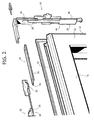
- Figure 2 is perspective view in enlarged scale of the part indicated by the arrow II in Figure 1,
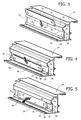
- Figures 3, 4 and 5 are perspective views that illustrate the mounting sequence of one of the drive elements or members according to the present invention, and
- Figures 6 and 7 are perspective views illustrating two alternative embodiments of one of the drive members.
- With reference to Figures 1 and 2, the
number 10 designates the movable frame of a window or door constituted by extruded section bars made of light alloy. Themovable frame 10 comprises two parallelvertical section bars 12 and twohorizontal section bars 14, only one of which is visible in the figures. Each of thesection bars longitudinal slot 16 with undercut cross section. - The
frame 10 is provided with a cremonebolt command device 18, (Figure 1) including ahandle 20 whereby the positions of closed window or door and open window or door can be selected. In the case of doors and window frames openable with swivel wing, thecremone bolt command 18 allows to select the positions of: closed window or door, window or door opened in wing mode and window or door open in swivel wing mode. - The
movable frame 10 is provided with drive assemblies globally designated with thenumbers movable frame 10. The drive assemblies comprise all devices and components which, under the command of thecremone bolt device 18, select the configurations of closed frame, wing-opened frame or swivel-opened frame. In particular, the drive assembly comprises the so-calledaccessories rods 26 which operatively connect the accessories to each other. - According to the present invention, the
accessories rods 26 which globally form the drive assembly are shaped in such a way as to be inserted into therespective slots 16 with a motion in transverse direction with respect to the longitudinal direction of the slot. With the solution according to the present invention, instead of inserting theaccessories transmission rods 26 in the longitudinal direction starting from one end of theslot 16, such components are inserted frontally in the manner that will be described below. - In the remainder of the description and in the claims the term "drive members" defines the members that engage in fastening relationship a
respective slot 16 or that are movable relative to theslot 16 between at least two operative positions corresponding to respective operative states of theframe 10, such as closed position, wing-opened position, swivel-opened position. In traditional solutions, each of said operating members is provided with two longitudinal tenons that engage opposite longitudinal edges of arespective slots 16. According to the present invention, each of the drive members of the drive assembly is provided with only one longitudinal tenon. In this way, each drive member is inserted into therespective slot 16 engaging the tenon in the undercut part of theslot 16 and making the drive member oscillate towards the slot in orthogonal direction to the longitudinal axis of the slot. - An example of the way in which the drive members according to the present invention are mounted on the door or window frame is described hereafter with reference to Figures 3 through 5. These figures illustrate the mounting of a connecting
rod 26. The same mounting sequence is used for any drive member comprised in the drive assembly. - With reference to Figures 3 through 5, the
section bar 14 of the frame (identical to the section bar 12) has a guidingslot 16 with abottom wall 28, twolateral walls 30 and twolongitudinal edges 32 oriented towards each other and parallel to thebottom wall 28. Thelongitudinal edges 32 define alongitudinal opening 34 whose width is smaller than the distance between thelateral walls 30 in such a way that, in its cross section, theslot 16 has an undercut profile. Each of thelongitudinal edges 32 has an outer surface, a front surface and an inner surface. The shapes of thesection bar 14 and of theslot 16 do not differ from known solutions and have been described only to allow a better understanding of the present invention. - The connecting
rod 26 according to the present invention has two parallellateral surfaces 36 separated from each other by a slightly smaller distance than the width of theopening 34. The connectingrod 26 is provided with a singlelongitudinal tenon 38 that extends parallel and below relative to one of thelateral surfaces 36. In the embodiment illustrated in Figures 3 to 5, the connectingrod 26 is also provided with twolongitudinal bearing edges 40 that project in lateral direction beyond thelateral surfaces 36. - The mounting sequence of the connecting
rod 26 provides for inserting thetenon 38 below alongitudinal edge 32 of theslot 16 until bringing thelongitudinal surface 36 adjacent to thetenon 38 in contact with the front surface of the edge 32 (Figures 3 and 4). Hence, the connectingrod 26 is made to oscillate towards the interior of theslot 16 as indicated by thearrow 42 in Figure 5 until bringing thebearing edge 40 in contact with the outer surface of the correspondinglongitudinal edge 32 of theslot 16. At this point, the mounting operation is complete. It can be noted that thelateral surfaces 36 of the connectingrod 26 are guided between the front surfaces of theedges 32 and thebearing edges 40 bear on the outer surfaces of the edges of 32 of theslot 16. - Figures 6 and 7 show a connecting rod obtained as described above (Figure 6) next to a modified version (Figure 7). In the modified version are not present the
bearing edges 40 and therod 26 is provided on the opposite longitudinal side relative to the tenon of a longitudinal bearingfoot 44 that is destined to bear on thebottom wall 28 of theslot 16. - The structural characteristics and the mounting modes described above in relation to the connecting
rods 26 apply to all the drive members of the drive assembly 22. For example, in Figure 2 thereference numbers angular transmission device 50 and of ascissors arm 52. Thedrive members single tenon 38 and, on the longitudinal side opposite thetenon 38, have a front surface 36 (dashed in Figure 3) lacking a tenon, in order to allow the insertion into the slot in transverse direction to the longitudinal direction of the slot, as described above for the connectingrod 26. - The solution described herein applies both to the door and window frames provided with a swivel wing opening motion, and to the door and window frames provided solely with a wing opening motion or solely with a swivel opening motion.
Claims (5)
- A drive assembly (22) for door and window frames (10), including a plurality of drive members (26, 46, 48) able to be inserted into elongated slots with undercut profile (16) of the door or window frame (10), characterised in that the drive members (26, 46, 48) can be inserted into the respective slots (16) with a movement in a transverse direction relative to the longitudinal direction of the slot (16).
- Drive assembly as claimed in claim 1, characterised in that each of said drive members (26, 46, 48) comprises two parallel lateral surfaces (36) and one single tenon (38) that extends parallel to one of said lateral surfaces (36).
- Drive assembly as claimed in claim 2, characterised in that each of said drive members (26, 46, 48) comprises at least one longitudinal bearing edge (40) projecting laterally beyond a corresponding lateral surface (36).
- Drive assembly as claimed in claim 3, characterised in that each of said drive members (26, 46, 48) comprises at least one pair of longitudinal bearing edges (40) projecting laterally beyond said lateral longitudinal surfaces (36).
- Drive assembly as claimed in claim 2, characterised in that each of said drive members (26, 46, 48) comprises a longitudinal bearing foot (44) situated on the opposite longitudinal edge with respect to the tenon (38).
Priority Applications (6)
| Application Number | Priority Date | Filing Date | Title |
|---|---|---|---|
| DE602005006234T DE602005006234T2 (en) | 2005-03-29 | 2005-03-29 | Drive unit for window and door frames |
| PT05425179T PT1707719E (en) | 2005-03-29 | 2005-03-29 | Drive assembly for door and window frames |
| PL05425179T PL1707719T3 (en) | 2005-03-29 | 2005-03-29 | Drive assembly for door and window frames |
| EP05425179A EP1707719B1 (en) | 2005-03-29 | 2005-03-29 | Drive assembly for door and window frames |
| AT05425179T ATE393281T1 (en) | 2005-03-29 | 2005-03-29 | DRIVE UNIT FOR WINDOW AND DOOR FRAME |
| ES05425179T ES2304679T3 (en) | 2005-03-29 | 2005-03-29 | DRIVE ASSEMBLY FOR WINDOW AND DOOR FRAMES. |
Applications Claiming Priority (1)
| Application Number | Priority Date | Filing Date | Title |
|---|---|---|---|
| EP05425179A EP1707719B1 (en) | 2005-03-29 | 2005-03-29 | Drive assembly for door and window frames |
Publications (2)
| Publication Number | Publication Date |
|---|---|
| EP1707719A1 true EP1707719A1 (en) | 2006-10-04 |
| EP1707719B1 EP1707719B1 (en) | 2008-04-23 |
Family
ID=35355417
Family Applications (1)
| Application Number | Title | Priority Date | Filing Date |
|---|---|---|---|
| EP05425179A Expired - Lifetime EP1707719B1 (en) | 2005-03-29 | 2005-03-29 | Drive assembly for door and window frames |
Country Status (6)
| Country | Link |
|---|---|
| EP (1) | EP1707719B1 (en) |
| AT (1) | ATE393281T1 (en) |
| DE (1) | DE602005006234T2 (en) |
| ES (1) | ES2304679T3 (en) |
| PL (1) | PL1707719T3 (en) |
| PT (1) | PT1707719E (en) |
Cited By (3)
| Publication number | Priority date | Publication date | Assignee | Title |
|---|---|---|---|---|
| EP1975353A1 (en) * | 2007-03-27 | 2008-10-01 | Hydro Aluminium As | Fitting for locking doors, windows or the like |
| EP1867822A3 (en) * | 2006-06-15 | 2010-03-10 | SAVIO S.p.A. | Door and window frame with an undercut engagement area for a drive assembly |
| EP4033056A1 (en) | 2021-01-14 | 2022-07-27 | SOBINCO, naamloze vennootschap | Connecting rail for window hardware |
Families Citing this family (1)
| Publication number | Priority date | Publication date | Assignee | Title |
|---|---|---|---|---|
| DE102024129291A1 (en) | 2024-10-10 | 2026-04-16 | Siegenia-Aubi Kg | Fastening of a drive rod fitting into a guide groove with undercuts in a sash for a window or door |
Citations (4)
| Publication number | Priority date | Publication date | Assignee | Title |
|---|---|---|---|---|
| DE3225049A1 (en) * | 1982-07-05 | 1984-01-12 | Geze Gmbh, 7250 Leonberg | Device for the coupling of espagnolettes extending perpendicularly to one another |
| FR2722527A1 (en) * | 1994-07-13 | 1996-01-19 | Alcan France | Locking mechanism for window frame with pivoting window |
| EP1256680A2 (en) * | 2001-05-09 | 2002-11-13 | Roto Frank Ag | Window, door or the like with espagnolette lock |
| EP1270856A2 (en) * | 2001-06-20 | 2003-01-02 | Norsk Hydro Asa | Fitting for locking of windows or doors |
-
2005
- 2005-03-29 EP EP05425179A patent/EP1707719B1/en not_active Expired - Lifetime
- 2005-03-29 DE DE602005006234T patent/DE602005006234T2/en not_active Expired - Lifetime
- 2005-03-29 ES ES05425179T patent/ES2304679T3/en not_active Expired - Lifetime
- 2005-03-29 AT AT05425179T patent/ATE393281T1/en not_active IP Right Cessation
- 2005-03-29 PL PL05425179T patent/PL1707719T3/en unknown
- 2005-03-29 PT PT05425179T patent/PT1707719E/en unknown
Patent Citations (4)
| Publication number | Priority date | Publication date | Assignee | Title |
|---|---|---|---|---|
| DE3225049A1 (en) * | 1982-07-05 | 1984-01-12 | Geze Gmbh, 7250 Leonberg | Device for the coupling of espagnolettes extending perpendicularly to one another |
| FR2722527A1 (en) * | 1994-07-13 | 1996-01-19 | Alcan France | Locking mechanism for window frame with pivoting window |
| EP1256680A2 (en) * | 2001-05-09 | 2002-11-13 | Roto Frank Ag | Window, door or the like with espagnolette lock |
| EP1270856A2 (en) * | 2001-06-20 | 2003-01-02 | Norsk Hydro Asa | Fitting for locking of windows or doors |
Cited By (6)
| Publication number | Priority date | Publication date | Assignee | Title |
|---|---|---|---|---|
| EP1867822A3 (en) * | 2006-06-15 | 2010-03-10 | SAVIO S.p.A. | Door and window frame with an undercut engagement area for a drive assembly |
| CN101089353B (en) * | 2006-06-15 | 2013-01-23 | 萨维奥股份有限公司 | Door and window frame |
| DE202006021264U1 (en) | 2006-06-15 | 2014-04-04 | Savio S.P.A. | Door and window frame with an undercut engagement area for a gear unit |
| EP1975353A1 (en) * | 2007-03-27 | 2008-10-01 | Hydro Aluminium As | Fitting for locking doors, windows or the like |
| EP4033056A1 (en) | 2021-01-14 | 2022-07-27 | SOBINCO, naamloze vennootschap | Connecting rail for window hardware |
| BE1029013A1 (en) | 2021-01-14 | 2022-08-09 | Sobinco Fa | Connecting batten for window fittings |
Also Published As
| Publication number | Publication date |
|---|---|
| EP1707719B1 (en) | 2008-04-23 |
| ES2304679T3 (en) | 2008-10-16 |
| DE602005006234T2 (en) | 2009-05-20 |
| PL1707719T3 (en) | 2008-09-30 |
| PT1707719E (en) | 2008-07-01 |
| DE602005006234D1 (en) | 2008-06-05 |
| ATE393281T1 (en) | 2008-05-15 |
Similar Documents
| Publication | Publication Date | Title |
|---|---|---|
| US7644538B2 (en) | Turn/tilt closure | |
| EP1491706A1 (en) | Transmission rod for accessories for windows and doors | |
| EP2881530A1 (en) | Sliding window | |
| ITTO20060434A1 (en) | "DRIVE UNIT FOR WINDOWS" | |
| US7340860B2 (en) | Safety assembly for a casement window or door | |
| EP1227207B1 (en) | Fitting for a window and parts for such fitting | |
| EP1707719A1 (en) | Drive assembly for door and window frames | |
| US9151094B2 (en) | Device for connecting door and window operating units | |
| KR100720957B1 (en) | Window structure with building security function | |
| HU220920B1 (en) | Sealing and bolt for windows, doors or similars | |
| KR102147697B1 (en) | Fitting of an at least liftable, but preferably also displaceable wing of windows or doors | |
| JP6748605B2 (en) | Door car and joinery | |
| ITMI20061180A1 (en) | LOCKING SYSTEM FOR WINDOWS AND FIXTURES INCLUDING THIS LOCKING SYSTEM | |
| GB2208524A (en) | Espagnolette drive mechanism | |
| KR200411765Y1 (en) | Wind-resistant reinforcement auxiliary unit of window | |
| JP2012001897A (en) | Double-hung window | |
| GB2210657A (en) | Drive mechanism; fastening closure member | |
| US7104010B2 (en) | Hermetic jalousie window hardware | |
| JP2004036381A (en) | Sliding screen device for door or window | |
| KR200341293Y1 (en) | Open and shut crime prevention door | |
| EP1743996A2 (en) | Operating unit for doors or windows | |
| GB2294493A (en) | Window frame reinforcement with a flange having a recess for a locking mechanism | |
| JP3610902B2 (en) | Construction structure of single sliding door | |
| JPH1060870A (en) | Water gate opening and closing device | |
| KR200389474Y1 (en) | Joint structure for frame of folding slide door |
Legal Events
| Date | Code | Title | Description |
|---|---|---|---|
| PUAI | Public reference made under article 153(3) epc to a published international application that has entered the european phase |
Free format text: ORIGINAL CODE: 0009012 |
|
| AK | Designated contracting states |
Kind code of ref document: A1 Designated state(s): AT BE BG CH CY CZ DE DK EE ES FI FR GB GR HU IE IS IT LI LT LU MC NL PL PT RO SE SI SK TR |
|
| AX | Request for extension of the european patent |
Extension state: AL BA HR LV MK YU |
|
| 17P | Request for examination filed |
Effective date: 20070315 |
|
| 17Q | First examination report despatched |
Effective date: 20070420 |
|
| AKX | Designation fees paid |
Designated state(s): AT BE BG CH CY CZ DE DK EE ES FI FR GB GR HU IE IS IT LI LT LU MC NL PL PT RO SE SI SK TR |
|
| GRAP | Despatch of communication of intention to grant a patent |
Free format text: ORIGINAL CODE: EPIDOSNIGR1 |
|
| GRAS | Grant fee paid |
Free format text: ORIGINAL CODE: EPIDOSNIGR3 |
|
| GRAA | (expected) grant |
Free format text: ORIGINAL CODE: 0009210 |
|
| AK | Designated contracting states |
Kind code of ref document: B1 Designated state(s): AT BE BG CH CY CZ DE DK EE ES FI FR GB GR HU IE IS IT LI LT LU MC NL PL PT RO SE SI SK TR |
|
| REG | Reference to a national code |
Ref country code: GB Ref legal event code: FG4D |
|
| REG | Reference to a national code |
Ref country code: CH Ref legal event code: EP Ref country code: CH Ref legal event code: NV Representative=s name: ISLER & PEDRAZZINI AG |
|
| REF | Corresponds to: |
Ref document number: 602005006234 Country of ref document: DE Date of ref document: 20080605 Kind code of ref document: P |
|
| REG | Reference to a national code |
Ref country code: IE Ref legal event code: FG4D Free format text: LANGUAGE OF EP DOCUMENT: FRENCH |
|
| REG | Reference to a national code |
Ref country code: PT Ref legal event code: SC4A Free format text: AVAILABILITY OF NATIONAL TRANSLATION Effective date: 20080619 |
|
| REG | Reference to a national code |
Ref country code: GR Ref legal event code: EP Ref document number: 20080401672 Country of ref document: GR |
|
| PG25 | Lapsed in a contracting state [announced via postgrant information from national office to epo] |
Ref country code: SI Free format text: LAPSE BECAUSE OF FAILURE TO SUBMIT A TRANSLATION OF THE DESCRIPTION OR TO PAY THE FEE WITHIN THE PRESCRIBED TIME-LIMIT Effective date: 20080423 |
|
| REG | Reference to a national code |
Ref country code: PL Ref legal event code: T3 |
|
| REG | Reference to a national code |
Ref country code: ES Ref legal event code: FG2A Ref document number: 2304679 Country of ref document: ES Kind code of ref document: T3 |
|
| PG25 | Lapsed in a contracting state [announced via postgrant information from national office to epo] |
Ref country code: BG Free format text: LAPSE BECAUSE OF FAILURE TO SUBMIT A TRANSLATION OF THE DESCRIPTION OR TO PAY THE FEE WITHIN THE PRESCRIBED TIME-LIMIT Effective date: 20080723 Ref country code: FI Free format text: LAPSE BECAUSE OF FAILURE TO SUBMIT A TRANSLATION OF THE DESCRIPTION OR TO PAY THE FEE WITHIN THE PRESCRIBED TIME-LIMIT Effective date: 20080423 |
|
| PG25 | Lapsed in a contracting state [announced via postgrant information from national office to epo] |
Ref country code: IS Free format text: LAPSE BECAUSE OF FAILURE TO SUBMIT A TRANSLATION OF THE DESCRIPTION OR TO PAY THE FEE WITHIN THE PRESCRIBED TIME-LIMIT Effective date: 20080823 |
|
| REG | Reference to a national code |
Ref country code: HU Ref legal event code: AG4A Ref document number: E004071 Country of ref document: HU |
|
| PG25 | Lapsed in a contracting state [announced via postgrant information from national office to epo] |
Ref country code: LT Free format text: LAPSE BECAUSE OF FAILURE TO SUBMIT A TRANSLATION OF THE DESCRIPTION OR TO PAY THE FEE WITHIN THE PRESCRIBED TIME-LIMIT Effective date: 20080423 Ref country code: DK Free format text: LAPSE BECAUSE OF FAILURE TO SUBMIT A TRANSLATION OF THE DESCRIPTION OR TO PAY THE FEE WITHIN THE PRESCRIBED TIME-LIMIT Effective date: 20080423 Ref country code: SE Free format text: LAPSE BECAUSE OF FAILURE TO SUBMIT A TRANSLATION OF THE DESCRIPTION OR TO PAY THE FEE WITHIN THE PRESCRIBED TIME-LIMIT Effective date: 20080723 Ref country code: CZ Free format text: LAPSE BECAUSE OF FAILURE TO SUBMIT A TRANSLATION OF THE DESCRIPTION OR TO PAY THE FEE WITHIN THE PRESCRIBED TIME-LIMIT Effective date: 20080423 |
|
| PLBI | Opposition filed |
Free format text: ORIGINAL CODE: 0009260 |
|
| ET | Fr: translation filed | ||
| PLAX | Notice of opposition and request to file observation + time limit sent |
Free format text: ORIGINAL CODE: EPIDOSNOBS2 |
|
| PG25 | Lapsed in a contracting state [announced via postgrant information from national office to epo] |
Ref country code: SK Free format text: LAPSE BECAUSE OF FAILURE TO SUBMIT A TRANSLATION OF THE DESCRIPTION OR TO PAY THE FEE WITHIN THE PRESCRIBED TIME-LIMIT Effective date: 20080423 Ref country code: RO Free format text: LAPSE BECAUSE OF FAILURE TO SUBMIT A TRANSLATION OF THE DESCRIPTION OR TO PAY THE FEE WITHIN THE PRESCRIBED TIME-LIMIT Effective date: 20080423 |
|
| 26 | Opposition filed |
Opponent name: SIEGENIA-AUBI KG Effective date: 20090121 |
|
| PLBP | Opposition withdrawn |
Free format text: ORIGINAL CODE: 0009264 |
|
| PG25 | Lapsed in a contracting state [announced via postgrant information from national office to epo] |
Ref country code: EE Free format text: LAPSE BECAUSE OF FAILURE TO SUBMIT A TRANSLATION OF THE DESCRIPTION OR TO PAY THE FEE WITHIN THE PRESCRIBED TIME-LIMIT Effective date: 20080423 |
|
| NLR1 | Nl: opposition has been filed with the epo |
Opponent name: SIEGENIA-AUBI KG |
|
| PLBB | Reply of patent proprietor to notice(s) of opposition received |
Free format text: ORIGINAL CODE: EPIDOSNOBS3 |
|
| PG25 | Lapsed in a contracting state [announced via postgrant information from national office to epo] |
Ref country code: MC Free format text: LAPSE BECAUSE OF NON-PAYMENT OF DUE FEES Effective date: 20090331 |
|
| PLBD | Termination of opposition procedure: decision despatched |
Free format text: ORIGINAL CODE: EPIDOSNOPC1 |
|
| PG25 | Lapsed in a contracting state [announced via postgrant information from national office to epo] |
Ref country code: IE Free format text: LAPSE BECAUSE OF NON-PAYMENT OF DUE FEES Effective date: 20090329 |
|
| PLBM | Termination of opposition procedure: date of legal effect published |
Free format text: ORIGINAL CODE: 0009276 |
|
| STAA | Information on the status of an ep patent application or granted ep patent |
Free format text: STATUS: OPPOSITION PROCEDURE CLOSED |
|
| 27C | Opposition proceedings terminated |
Effective date: 20091123 |
|
| PGFP | Annual fee paid to national office [announced via postgrant information from national office to epo] |
Ref country code: CH Payment date: 20100323 Year of fee payment: 6 Ref country code: HU Payment date: 20100312 Year of fee payment: 6 |
|
| PGFP | Annual fee paid to national office [announced via postgrant information from national office to epo] |
Ref country code: AT Payment date: 20100312 Year of fee payment: 6 |
|
| PG25 | Lapsed in a contracting state [announced via postgrant information from national office to epo] |
Ref country code: LU Free format text: LAPSE BECAUSE OF NON-PAYMENT OF DUE FEES Effective date: 20090329 |
|
| PG25 | Lapsed in a contracting state [announced via postgrant information from national office to epo] |
Ref country code: CY Free format text: LAPSE BECAUSE OF FAILURE TO SUBMIT A TRANSLATION OF THE DESCRIPTION OR TO PAY THE FEE WITHIN THE PRESCRIBED TIME-LIMIT Effective date: 20080423 |
|
| REG | Reference to a national code |
Ref country code: CH Ref legal event code: PL |
|
| PG25 | Lapsed in a contracting state [announced via postgrant information from national office to epo] |
Ref country code: AT Free format text: LAPSE BECAUSE OF NON-PAYMENT OF DUE FEES Effective date: 20110329 |
|
| PG25 | Lapsed in a contracting state [announced via postgrant information from national office to epo] |
Ref country code: HU Free format text: LAPSE BECAUSE OF NON-PAYMENT OF DUE FEES Effective date: 20110330 Ref country code: LI Free format text: LAPSE BECAUSE OF NON-PAYMENT OF DUE FEES Effective date: 20110331 Ref country code: CH Free format text: LAPSE BECAUSE OF NON-PAYMENT OF DUE FEES Effective date: 20110331 |
|
| REG | Reference to a national code |
Ref country code: FR Ref legal event code: PLFP Year of fee payment: 12 |
|
| REG | Reference to a national code |
Ref country code: FR Ref legal event code: PLFP Year of fee payment: 13 |
|
| PGFP | Annual fee paid to national office [announced via postgrant information from national office to epo] |
Ref country code: GR Payment date: 20170327 Year of fee payment: 13 Ref country code: NL Payment date: 20170327 Year of fee payment: 13 Ref country code: FR Payment date: 20170327 Year of fee payment: 13 |
|
| PGFP | Annual fee paid to national office [announced via postgrant information from national office to epo] |
Ref country code: BE Payment date: 20170328 Year of fee payment: 13 Ref country code: PL Payment date: 20170322 Year of fee payment: 13 Ref country code: GB Payment date: 20170330 Year of fee payment: 13 |
|
| REG | Reference to a national code |
Ref country code: NL Ref legal event code: MM Effective date: 20180401 |
|
| GBPC | Gb: european patent ceased through non-payment of renewal fee |
Effective date: 20180329 |
|
| REG | Reference to a national code |
Ref country code: BE Ref legal event code: MM Effective date: 20180331 |
|
| PG25 | Lapsed in a contracting state [announced via postgrant information from national office to epo] |
Ref country code: NL Free format text: LAPSE BECAUSE OF NON-PAYMENT OF DUE FEES Effective date: 20180401 |
|
| PG25 | Lapsed in a contracting state [announced via postgrant information from national office to epo] |
Ref country code: GR Free format text: LAPSE BECAUSE OF NON-PAYMENT OF DUE FEES Effective date: 20181003 |
|
| PG25 | Lapsed in a contracting state [announced via postgrant information from national office to epo] |
Ref country code: GB Free format text: LAPSE BECAUSE OF NON-PAYMENT OF DUE FEES Effective date: 20180329 Ref country code: BE Free format text: LAPSE BECAUSE OF NON-PAYMENT OF DUE FEES Effective date: 20180331 |
|
| PG25 | Lapsed in a contracting state [announced via postgrant information from national office to epo] |
Ref country code: FR Free format text: LAPSE BECAUSE OF NON-PAYMENT OF DUE FEES Effective date: 20180331 |
|
| PG25 | Lapsed in a contracting state [announced via postgrant information from national office to epo] |
Ref country code: PL Free format text: LAPSE BECAUSE OF NON-PAYMENT OF DUE FEES Effective date: 20180329 |
|
| PG25 | Lapsed in a contracting state [announced via postgrant information from national office to epo] |
Ref country code: TR Free format text: LAPSE BECAUSE OF NON-PAYMENT OF DUE FEES Effective date: 20180329 |
|
| PGFP | Annual fee paid to national office [announced via postgrant information from national office to epo] |
Ref country code: PT Payment date: 20230317 Year of fee payment: 19 Ref country code: IT Payment date: 20230321 Year of fee payment: 19 Ref country code: DE Payment date: 20230328 Year of fee payment: 19 |
|
| REG | Reference to a national code |
Ref country code: DE Ref legal event code: R081 Ref document number: 602005006234 Country of ref document: DE Owner name: SAVIO S.P.A., CHIUSA DI SAN MICHELE, IT Free format text: FORMER OWNER: SAVIO S.P.A., CHIUSA DI SAN MICHELE, TURIN, IT Ref country code: DE Ref legal event code: R081 Ref document number: 602005006234 Country of ref document: DE Owner name: SAVIO THESAN GROUP S.P.A., IT Free format text: FORMER OWNER: SAVIO S.P.A., CHIUSA DI SAN MICHELE, TURIN, IT |
|
| PGFP | Annual fee paid to national office [announced via postgrant information from national office to epo] |
Ref country code: ES Payment date: 20230424 Year of fee payment: 19 |
|
| REG | Reference to a national code |
Ref country code: DE Ref legal event code: R081 Ref document number: 602005006234 Country of ref document: DE Owner name: SAVIO S.P.A., CHIUSA DI SAN MICHELE, IT Free format text: FORMER OWNER: SAVIO THESAN GROUP S.P.A., CHIUSA SAN MICHELE, IT Ref country code: DE Ref legal event code: R082 Ref document number: 602005006234 Country of ref document: DE Representative=s name: GULDE & PARTNER PATENT- UND RECHTSANWALTSKANZL, DE |
|
| REG | Reference to a national code |
Ref country code: ES Ref legal event code: PC2A Owner name: SAVIO S.P.A. Effective date: 20240626 |
|
| REG | Reference to a national code |
Ref country code: DE Ref legal event code: R119 Ref document number: 602005006234 Country of ref document: DE |
|
| PG25 | Lapsed in a contracting state [announced via postgrant information from national office to epo] |
Ref country code: DE Free format text: LAPSE BECAUSE OF NON-PAYMENT OF DUE FEES Effective date: 20241001 |
|
| PG25 | Lapsed in a contracting state [announced via postgrant information from national office to epo] |
Ref country code: DE Free format text: LAPSE BECAUSE OF NON-PAYMENT OF DUE FEES Effective date: 20241001 |
|
| PG25 | Lapsed in a contracting state [announced via postgrant information from national office to epo] |
Ref country code: IT Free format text: LAPSE BECAUSE OF NON-PAYMENT OF DUE FEES Effective date: 20240329 |
|
| REG | Reference to a national code |
Ref country code: ES Ref legal event code: FD2A Effective date: 20250506 |
|
| PG25 | Lapsed in a contracting state [announced via postgrant information from national office to epo] |
Ref country code: ES Free format text: LAPSE BECAUSE OF NON-PAYMENT OF DUE FEES Effective date: 20240330 |
|
| PG25 | Lapsed in a contracting state [announced via postgrant information from national office to epo] |
Ref country code: PT Free format text: LAPSE BECAUSE OF EXPIRATION OF PROTECTION Effective date: 20250409 |
|
| PG25 | Lapsed in a contracting state [announced via postgrant information from national office to epo] |
Ref country code: PT Free format text: LAPSE BECAUSE OF NON-PAYMENT OF DUE FEES Effective date: 20240329 |