EP1705955A1 - Audio signal supplying apparatus for speaker array - Google Patents
Audio signal supplying apparatus for speaker array Download PDFInfo
- Publication number
- EP1705955A1 EP1705955A1 EP05703397A EP05703397A EP1705955A1 EP 1705955 A1 EP1705955 A1 EP 1705955A1 EP 05703397 A EP05703397 A EP 05703397A EP 05703397 A EP05703397 A EP 05703397A EP 1705955 A1 EP1705955 A1 EP 1705955A1
- Authority
- EP
- European Patent Office
- Prior art keywords
- directivity
- audio signal
- loudspeaker
- delay
- control information
- Prior art date
- Legal status (The legal status is an assumption and is not a legal conclusion. Google has not performed a legal analysis and makes no representation as to the accuracy of the status listed.)
- Granted
Links
Images



Classifications
-
- H—ELECTRICITY
- H04—ELECTRIC COMMUNICATION TECHNIQUE
- H04R—LOUDSPEAKERS, MICROPHONES, GRAMOPHONE PICK-UPS OR LIKE ACOUSTIC ELECTROMECHANICAL TRANSDUCERS; ELECTRIC HEARING AIDS; PUBLIC ADDRESS SYSTEMS
- H04R1/00—Details of transducers, loudspeakers or microphones
- H04R1/20—Arrangements for obtaining desired frequency or directional characteristics
- H04R1/32—Arrangements for obtaining desired frequency or directional characteristics for obtaining desired directional characteristic only
- H04R1/40—Arrangements for obtaining desired frequency or directional characteristics for obtaining desired directional characteristic only by combining a number of identical transducers
- H04R1/403—Arrangements for obtaining desired frequency or directional characteristics for obtaining desired directional characteristic only by combining a number of identical transducers loud-speakers
-
- H—ELECTRICITY
- H04—ELECTRIC COMMUNICATION TECHNIQUE
- H04R—LOUDSPEAKERS, MICROPHONES, GRAMOPHONE PICK-UPS OR LIKE ACOUSTIC ELECTROMECHANICAL TRANSDUCERS; ELECTRIC HEARING AIDS; PUBLIC ADDRESS SYSTEMS
- H04R5/00—Stereophonic arrangements
- H04R5/04—Circuit arrangements, e.g. for selective connection of amplifier inputs/outputs to loudspeakers, for loudspeaker detection, or for adaptation of settings to personal preferences or hearing impairments
-
- H—ELECTRICITY
- H04—ELECTRIC COMMUNICATION TECHNIQUE
- H04R—LOUDSPEAKERS, MICROPHONES, GRAMOPHONE PICK-UPS OR LIKE ACOUSTIC ELECTROMECHANICAL TRANSDUCERS; ELECTRIC HEARING AIDS; PUBLIC ADDRESS SYSTEMS
- H04R2205/00—Details of stereophonic arrangements covered by H04R5/00 but not provided for in any of its subgroups
- H04R2205/022—Plurality of transducers corresponding to a plurality of sound channels in each earpiece of headphones or in a single enclosure
-
- H—ELECTRICITY
- H04—ELECTRIC COMMUNICATION TECHNIQUE
- H04R—LOUDSPEAKERS, MICROPHONES, GRAMOPHONE PICK-UPS OR LIKE ACOUSTIC ELECTROMECHANICAL TRANSDUCERS; ELECTRIC HEARING AIDS; PUBLIC ADDRESS SYSTEMS
- H04R2205/00—Details of stereophonic arrangements covered by H04R5/00 but not provided for in any of its subgroups
- H04R2205/041—Adaptation of stereophonic signal reproduction for the hearing impaired
-
- H—ELECTRICITY
- H04—ELECTRIC COMMUNICATION TECHNIQUE
- H04R—LOUDSPEAKERS, MICROPHONES, GRAMOPHONE PICK-UPS OR LIKE ACOUSTIC ELECTROMECHANICAL TRANSDUCERS; ELECTRIC HEARING AIDS; PUBLIC ADDRESS SYSTEMS
- H04R2430/00—Signal processing covered by H04R, not provided for in its groups
- H04R2430/20—Processing of the output signals of the acoustic transducers of an array for obtaining a desired directivity characteristic
Definitions
- the first delay circuit 300 performs a delay process Lo provide the wide directivity for individual audio signals, and transmits the audio signals to corresponding multipliers 51.0-k.
- the second delay circuit 300' performs a delay process to provide the narrow directivity for individual audio signals, and transmits the audio signals to corresponding multipliers 510'-k.
- the multipliers 510-k and 510'-k add weights, using predetermined weighting coefficients, to the audio signals obtained through the delay processes, and transmit the resultant audio signals to an adding unit 900.
- the wide directivity is obtained by performing delay control.
- the wide directivity may also be provided by performing weighting control as explained in the first mode.
- the configuration for the second mode (arranging delay circuits inparallel, etc.) may be employed for the array loudspeaker system 100'' of the first mode so as to obtain the narrow directivity in two directions.
Landscapes
- Physics & Mathematics (AREA)
- Engineering & Computer Science (AREA)
- Acoustics & Sound (AREA)
- Signal Processing (AREA)
- Health & Medical Sciences (AREA)
- Otolaryngology (AREA)
- Circuit For Audible Band Transducer (AREA)
- Obtaining Desirable Characteristics In Audible-Bandwidth Transducers (AREA)
- Stereophonic System (AREA)
Abstract
Description
- The present invention relates to an audio signal supply apparatus that supplies an audio signal, such as a sound, to a loudspeaker array that is constituted by a plurality of loudspeaker units.
- In recent years, large, thin televisions, such as plasma televisions and liquid crystal televisions, have rapidly spread to average homes. These large, thin televisions used to have problems resulting from small viewing angles. However, through various improvements, the problems with viewing angles have been largely eliminated, and when televisions are installed in a spacious room, we can view scenes from various locations. While much consideration has been given to improving pictures, as described above, sounds have not been much taken into account. For example, many loudspeakers employed for large, thin televisions are a combination of conventional loudspeakers, such as two-way loudspeakers, that have dipole type directional characteristics (see, for example, patent document 1).
- Patent Document 1:
Japanese Patent Laid-Open Publication No. Hei 11-69474 - However, for a large, thin television that employs the above described loudspeakers, a problem is that the audio quality around the loudspeakers is deteriorated in location off the front of the loudspeakers. Further, in order to hear a clear sound at a location not near a television, Lhe volume of the loudspeakers must be increased. However, a problem is that at midnight, when sound can bother other people, or in a non-soundproofed house in a densely built-up area, the volume can not be turned up high, and earphones or headphones must be employed for listening.
- The present invention is providedwhile taking into account the above described problems, and one objective of the present invention is to provide an array loudspeaker audio signal supply apparatus that can achieve wide directivity and can also achieve efficient directivity that permits an audience to clearly hear sounds at a low volume.
- To resolve the above problems, an audio signal supply apparatus according to the present invention, which supplies an audio signal to a loudspeaker array constituted by a plurality of loudspeaker units, is characterized by comprising:
- delay means, for performing, in accordance with delay control information that is provided, a delay process for each audio signal to be supplied to the loudspeaker units;
- weighting means, for weighting, in accordance with gain control information that is provided, each audio signal to be supplied to the loudspeaker units;
- storage means, for storing a first directivity parameter, used to regard a directional characteristic for the loudspeaker as a narrow directivity, and a second directivity parameter, used to regard the directional characteristic for the loudspeaker as a wide directivity;
- input means, for receiving a selection instruction for the directional characteristics; and
- directivity control means, for selecting one of the directivity parameters in accordance with the selection instruction that is input, for employing the selected directivity parameter to generate the delay control information and the gain control information, and for supplying the delay control information and the gain control information to the delay means and the weighting means.
- According to this configuration, using a remote controller, a user need only perform a simple operation to select the directional characteristics for the loudspeaker array. Then, the user can switch between narrow directivity, such that, although the volume is low as a whole, the sound can be heard at a sufficient volume at a location in an arbitrary direction (a focal direction), and a wide directivity, such that the sound having high quality can be heard, regardless of audience locations.
- Furthermore, according to Lhe above described configuration, the selection instruction designating the selection of the narrow directivity includes position information for determining the direction of the directivity. When the selection instruction designating the selection of the narrow directivity is received, the directivity control means may select the first directivity parameter and may generate the delay control information based on the selected first directivity parameter and the position information.
- Further, another audio signal supply apparatus according to the present invention, which supplies an audio signal to a loudspeaker array constituted by a plurality of loudspeaker units, is characterized by comprising:
- branching means, for branching an input audio signal to provide two or more signals;
- first processing means, for performing, in accordance with first directivity control information that is provided, a delay process and/or weighting for each signal that is obtained by branching one audio signal and that is to be supplied to the loudspeaker units;
- second processing means, for performing, in accordance with second directivity control information that is provided, a delay process and/or weighting for each signal that is obtained by branching one audio signal and that is to be supplied to the loudspeaker units;
- directivity control means, for generating the first directivity control information and the second directivity control information so that directional characteristic of the loudspeaker array obtained by the first process differs from directional characteristic of the loudspeaker array obtained by the second process, and for supplying the thus generated information respectively to the first processing means and the second processing means; and
- adding means, for adding the audio signal that has been processed by the first processing means to the audio signal that has been processed by the second processing means.
- According to this configuration, one audio signal can be output that has two different directional characteristics simultaneously. Therefore, when, for example, as shown in Fig. 10, a hearing-unimpaired person and a hearing-impaired person listen to music in the same space (e.g., a living room),
musical sounds 2, for hearing-unimpaired persons, are output with wide directivity, whilemusical sounds 1, for hearing-impaired persons, are output with narrow directivity toward the hearing-impaired person. Thus, both a hearing-unimpaired person and a hearing-impaired person can listen Lo music at their appropriate volumes. - Moreover, according to the above configuration, the directional characteristic of the loudspeaker array obtained through the first process may be a narrow directivity, and the directional characteristic of the loudspeaker array obtained through the second process may be a wide directivity (see Fig. 10). Further, the directional characteristics for the loudspeaker array obtained through the individual processes may be narrow directivities that are aimed in different directions (see Fig. 11).
- In addition, frequency property correction means, for correcting a frequency property for signals that are obtained by branching one audio signal, is arranged between the branching means and the first process means. In accordance with the first directivity control information that is provided, the first process means may process each of the audio signals, for which the frequency property has been corrected and which are to be supplied to the loudspeaker units.
- As described above, according to the present invention, a wide directivity can be provided, and an efficient directivity can also be provided such that, at a small volume, a listener can still clearly hear sounds.
-
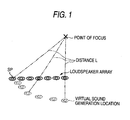
- Fig. 1 is a diagram for explaining directivity control of a delay array type according to the first basic theory;
- Fig. 2 is a diagram showing an example directional distribution for a loudspeaker according to this theory;
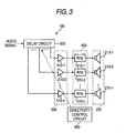
- Fig. 3 is a diagram showing the configuration of the essential section of an array loudspeaker system that employs this theory;
- Fig. 4 is a diagram showing the arrangement of the essential section of an array loudspeaker system that employs a Bessel array method according to a second basic theory;
- Fig. 5 is a diagram showing a relation between the locations of the individual loudspeaker units and gains according to this theory;
- Fig. 6 is a diagram showing the arrangement of the essential section of an array loudspeaker system according to a first mode;
- Fig. 7 is a diagram showing an example operating screen according to Lhe mode;
- Fig. 8 is a diagram showing an example operating screen according to the mode;
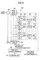
- Fig. 9 is a diagram showing the arrangement of the essential section of an array loudspeaker system according to a second mode;
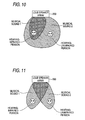
- Fig. 1.0 is a diagram showing an example directivity control pattern according to the mode; and
- Fig. 11 is a diagram showing a directivity control pattern according to the mode.
- Before the individual modes according to the present invention are described, the basic theory of the present invention will first be explained.
- Fig. 1 is a diagram for explaining directivity control of a delay array type that employs a loudspeaker array (constituted by a plurality of small loudspeaker units SP) according to a first basic theory. When the amount of a delay, which is consonant with a difference between the path from the center of the loudspeaker array to a specific point (point of focus) in space and the path from the loudspeaker units SP to the point of focus, is given to an audio signal that is to be supplied to the loudspeaker units SP, sound waves output by the individual loudspeaker units SP reach the point of focus at the same time. That is, the loudspeaker units SP can be regarded as being located at virtual sound generation locations (locations where distances L from the point of focus are equal) indicated by broken lines in Fig. 1, and the sound pressure near the point of focus is locally raised.
- Fig. 2 is a diagram showing an example directional distribution of a loudspeaker array that employs a delay array system, and the contour of the sound pressure for each 3 dB is indicated by a solid line. For the loudspeaker array, it is assumed that loudspeaker units are arranged linearly at intervals of about 5 cm within a width of 100 cm (x = -50 to 50 cm in Fig. 2). As shown in this diagram, for the loudspeaker array that employs the delay array system, such a directional distribution was obtained that it looks as though a sound wave beam was emitted toward the point of focus.
- The arrangement of the essential section of an
array loudspeaker system 100 that employs this delay array system is shown in Fig. 3. Thearray loudspeaker system 100 includes: aloudspeaker array 200, constituted by a plurality of speaker units 210-k (l ≤ k ≤ n); adelay circuit 300; adirectivity control apparatus 400; aweighting unit 500; and anamplification unit 600. Generally, an A/D converter and a D/A converter are provided at the front stage of thedelay circuit 300, the front stage of theamplification unit 600, etc.; however, they are not shown, for simplification. - In accordance with delay control information provided by the
directivity control apparatus 400, thedelay circuit 300 performs a delay process for each audio signal to be supplied to the loudspeaker units 210-k. In order to form a point of focus at a desired position, thedirectivity control apparatus 400 obtains the amounts of delays tobe provided for the individual audio signals, generates delay control information that represents the obtained amounts of delays, and supplies the delay control information to thedelay circuit 300. Specifically, the spatial coordinates of the individual loudspeaker units 210-k and the spatial coordinates of the point of focus are employed, and the amounts of delays are calculated so as to compensate for differences in distances from the point of focus to the individual loudspeaker units 210-k (see Fig. 1). - The
weighting unit 500 is constituted by the same number of multipliers 510-k as the loudspeaker units 210-k, and adds to the audio signals, which are obtained through the delay process and which are transmitted by thedelay circuit 300, a weight using a weight coefficient, such as a window function coefficient or a gain coefficient. Theamplification unit 600 is constituted by the same number of amplifiers 610-k as the loudspeaker units 210-k, and amplifies the audio signals from theweighting unit 500. The audio signals amplified by theamplification unit 600 are transmitted to the individual loudspeaker units 210-k that constitute theloudspeaker array 200, and are output as sound waves. The sound waves output by the loudspeaker units 210-k acquire the same phase at an arbitrary point (point of focus) in space, and the efficient directivity (hereinafter, a narrow directivity), where the sound pressure in the point of focal direction is locally high, is provided. - As described above, according to the
array loudspeaker system 100 that employs the delay array system, the narrow directivity can be provided and the direction of the directivity can be arbitrarily changed simply by varying the amount of delay. - An explanation will be given for directivity control of a Bessel array type that employs a loudspeaker array according to a second basic theory. The Bessel array is a method whereby an array (a loudspeaker array) of loudspeaker units that are arranged regularly is weighted by using a coefficient based on the Bessel function, so that the spherical radiation characteristics of sounds are obtained. Since this theory is conventionally well known, no further explanation for this will be given, but a reference document for this is, for example, "Multiple loudspeaker arrays using Bessel coefficients" (W. J. W. KITZEN, ELECTRONIC COMPONENTS AND APPLICATIONS, VOL. 5 NO. 4, SEPTEMBER 1983).
- The Bessel array is widely used as a method for providing wide directivity, such that music sounds, etc., can reach to all off an audience present in a large space, while a large volume is obtained by increasing the number of loudspeaker units. Fig. 4 is a diagram showing the arrangement of the essential section of an array loudspeaker system 100' that employs the Bessel array method. Fig. 5 is a diagram showing an example relation between the locations of loudspeaker units 210-k, which constitute the
loudspeaker array 200, and gains. In these diagrams, the same signs are provided for the portions corresponding to those in Fig. 3, and no detailed explanation for them will be given. - A
loudspeaker array 200 shown in Figs. 4 and 5 is constituted by seven loudspeaker units 210-1 to -7, which are arranged linearly at about the same intervals. Multipliers 510-1 to -7 that constitute aweighting unit 500 add to audio signals, 210-1 to -7, weights (gains) using Bessel array coefficients C1 to C7, which are introduced by the Bessel function. Since the weighting process based on the Bessel function is performed in this manner, directivity (hereinafter wide directivity) for which iL appears a nondirectional simple sound source radially emitted a sound wave is provided. - The details of the individual basic theories according to the present invention have been explained. A first mode that employs these basic theories will now be described.
- Fig. 6 is a diagram showing the arrangement of the essential section of an array loudspeaker system 100'' according to the first mode. The array loudspeaker system 100'' is a system that provides switching between (selection of) a narrow directivity and a wide directivity, and includes the essential section of the
loudspeaker system 100 of the delay array type in Fig. 3, and the essential section of the array loudspeaker system 100' of the Bessel array type in Fig. 5. It should be noted that the same signs are provided for portions corresponding to those in Figs. 3 and 5, and no detailed explanation for them will be given. - Loudspeaker units 210-k are small loudspeaker units having individual diameters of several cm or smaller. As is well known, since small loudspeaker units have a wide directivity that is almost nondirectional across a wide frequency range, a very wide directivity can be obtained by a directivity control that uses the Bessel array method. Further, for a directivity control of a delay array type, the focal direction can be widely aimed, to the left and right. In addition, when small loudspeaker units are arranged closely, an audio signal in a high frequency area can be controlled.
- A first directivity parameter P1 and a second directivity parameter P2 are stored in a directivity control apparatus (storage means) 400. The first directivity parameter P1 is a parameter for providing a narrow directivity such that sound waves output by the individual loudspeaker units 210-k advance in an arbitrary direction (a focal direction). The second directivity parameter is a parameter for providing a wide directivity such that sound waves output by the loudspeaker units 210-k spread through the entire space. The directivity control apparatus (directivity controlmeans) 400 selects either the first directivity parameter P1 or the second directivity parameter P2, in accordance with an instruction, supplied by an
operating unit 700, for selecting the directional characteristic of aloudspeaker array 200, and generates delay control information and gain control information based on the selected directivity parameter (details will be described later). - The operating unit (input means) 700 is means for entering, for example, an instruction for selecting the directional characteristic of the
loudspeaker array 200, and is constituted by various operating buttons, a remote controller, etc. Fig. 7 is a diagram showing an example operating screen g1 to be displayed on a.display device (e.g., a plasma television, etc.) connected to the array loudspeaker system 100 ''. A message to select either a wide directivity or a narrow directivity is displayed on the operating screen g1. Following this message, a user selects one of the directional characteristics by, for example, manipulating a remote controller. When a narrow directivity, for example, is selected in a case, an operating screen g2 in Fig. 8 is displayed on the display device. The user moves a hearing position icon I1, displayed on the operating screen g2, to a desired position by using, for example, a remote controller (see broken line in Fig. 8). Once such a series of processes has been performed, theoperating unit 700 supplies, to thedirectivity control apparatus 400, a selection instruction to select the narrow directivity and position information indicating the hearing position (position information for determining the direction of the directivity). - The
directivity control apparatus 400 selects the first directivity parameter P1 in accordance with the selection instruction received from theoperating unit 700, and determines a focal position, etc., based on the received position information. And based on the selected first directivity parameter P1, the determined focal, position, etc., thedirectivity control apparatus 400 obtains the amounts of delays, which are to be provided for audio signals that are to be transmitted to the individual loudspeaker units 210-k, generates delay control information that indicates the obtained amounts of delays, and transmits the delay control information to a delay circuit (delay means) 300. At the same time, based on the selected first directivity parameter P1, thedirectivity control apparatus 400 obtains a coefficient (in this case, an appropriate window function coefficient) to be multiplied by audio signals that are to be transmitted to the loudspeaker units 210-k, and transmits the coefficient to aweighting unit 500. As a result, the phase of an audio signal entered into the array loudspeaker system 100'' is adjusted by thedelay circuit 300, a weight using the window function coefficient is added to the resultant signals by theweighting unit 500, and the obtained signals are output as sound waves by the corresponding loudspeaker units 210-k. The sound waves output via the loudspeaker units 210-k have the same phase as an arbitrary point (the point of focus) in space, so that a narrow directivity desired by a user can be obtained. - On the other hand, in the state wherein the operating screen gl is displayed on the display device, when a wide directivity is selected by user manipulation of a remote controller, etc., the
operating unit 700 transmits to the directivity control apparatus 400 a selection instruction indicating that a wide directivity should be selected. Thedirectivity control apparatus 400 selects the second directivity parameter P2 in accordance with the selection instruction received from theoperating unit 700. Then, in accordance with the selected second directivity parameter P2, thedirectivity control apparatus 400 calculates the amounts of delays to be provided for audio signals, which are to be transmitted to the individual loudspeaker units 210-k, and a coefficient to be multiplied by the individual audio signals. In this case, since the second directivity parameter P2 for obtaining the wide directivity is selected, thedirectivity control apparatus 400 obtains the amount "0" for the delay, or if not "0", the same amount of delay, and a Bessel array coefficient introduced by the Bessel function. Thedirectivity control apparatus 400 generates delay control information and gain control information that represent the amount of delay and the coefficient, and transmits the information respectively to thedelay circuit 300 and theweighting unit 500. As a result, the audio signal input to the array loudspeaker system 100'' is weighted, using the Bessel array coefficient, by theweighting unit 500, so that wide directivity is provided. - As described above, according to the array loudspeaker system 100'' of the first mode, it is possible to switch between narrow directivity, such that sound can be heard with sufficient volume in an arbitrary direction (focal direction) though the volume, on the whole, is low, and wide directivity, such that sound wj th high quality can be heard regardless of the listening location.
- According to the above example, wide directivity has been provided by employing the Bessel array method. However, a method whereby the point of a focus is generated immediately near the front center of the
loudspeaker array 200 by controlling the above described amounts of delays, or a simulation method whereby musical sounds are output at an arbitrary point behind theloudspeaker array 200, may be employed to provide wide directivity. These methods can be provided by using the configuration of the array loudspeaker system 100''. - In the first mode described above, as an example, either wide directivity or narrow directivity has been selectable. An explanation will be given for a second mode below wherein both wide directivity and narrow directivity are established at the same time.
- In the present rapidly aging society, opportunities have increased during which an elderly person, etc., whose hearing capability has declined (hereinafter referred to as a hearing-impaired person) and a hearing-unimpaired person watch one television, etc., at home. In this case, the volume for listening tends to be a problem. For example, a volume appropriate for a person is too low for a hearing-impaired person to listen to, or when a volume is adjusted for a hearing-impaired person, the volume is too high for a hearing-unimpaired.
- Under these circumstances, there have been proposed a method for providing special loudspeakers for hearing-impaired people (see, for example,
Japanese Patent Laid-Open Publication No. 2000-197196 Japanese Patent Laid-Open Publication No. Hei 11-136788 - However, according to the method disclosed in the above described
Japanese Patent Laid-Open Publication No. 2000-197196 Japanese Patent Laid-Open Publication No. Hei 11-136788 - The invention of the second mode is provided while taking these conventional problems into account, and the objective is to provide, for example, musical sounds that satisfy both a hearing-impaired person whose hearing capability has declined and a hearing-unimpaired person when they listen to music together.
- Fig. 9 is a diagram showing the configuration of the essential section of an array loudspeaker system 100''' according to the second mode. In the array loudspeaker system 100''', the same signs are provided for the portions corresponding to those of the array loudspeaker system 100'' in Fig. 6, and no detailed explanation for them will be given. In addition, in the following explanation, assume the case is one wherein both a wide directivity and a narrow directivity are to be provided by performing delay control.
- A branching
unit 800 branches, into two, an audio signal that is input to the array loudspeaker system 100''', and transmits the branched audio signals to afirst delay circuit 300 and a second delay circuit 300'. - In accordance with first delay control information and second delay control information respectively received from
directivity control apparatus 400, thefirst delay circuit 300 and the second delay circuit 300' perform a delay process for audio signals to be transmitted to individual loudspeaker units 210-k. The directivity control apparatus (directivity control means) 400 generates the first delay control information and the second delay control information so that thedelay circuits 300 and 300' obtain different directional, characteristics. Specifically, when, as shown in Fig. 10, for hearing, a hearing-unimpaired person is positioned on a little obliquely left in front, viewed from theloudspeaker 200, and a hearing-impaired person is positioned on a little obliquely right in front, the first delay control information and the second delay control information are generated, so thatmusical sounds 2 for hearing-unimpaired people are output with a wide directivity, whilemusical sounds 1 for hearing-impaired people arc output with a narrow directivity toward the hearing-impaired person. It should be noted that the hearing positions of the hearing-impaired person and the hearing-unimpaired person can be entered by manipulating a remote controller, etc. In the following explanation, for the sake of convenience, assume the case is one wherein the wide directivity is provided by thefirst delay circuit 300 and the narrow directivity is provided by the second delay circuit 300'. - The
first delay circuit 300 performs a delay process Lo provide the wide directivity for individual audio signals, and transmits the audio signals to corresponding multipliers 51.0-k. On the other hand, the second delay circuit 300' performs a delay process to provide the narrow directivity for individual audio signals, and transmits the audio signals to corresponding multipliers 510'-k. The multipliers 510-k and 510'-k add weights, using predetermined weighting coefficients, to the audio signals obtained through the delay processes, and transmit the resultant audio signals to an addingunit 900. - The adding
unit 900 is constituted by the same number of adders 910-k as the loudspeaker units 210-k. The individual adders 910-k add the audio signals received from the corresponding multipliers 510-k and 510'-k. The audio signals obtained by the adders 910-k are transmitted through amplifiers 610-k to the corresponding loudspeaker units 210-k. - As a result, as shown in Fig. 10, the
musical sounds 2 for hearing-unimpairedpeople are output through theloudspeaker array 200 with the wide directivity, while themusical sounds 1 for hearing-impaired people are output through theloudspeaker array 200 with the narrow directivity. Thus, when a hearing-impaired person and a hearing-unimpaired person listen to music together in the same space (e.g., in a living room), both of them can enjoy music with satisfactory sounds. - In this case, an equalizer (frequency property correction means) may be provided at the front stage of either the
first delay circuit 300 or the second delay circuit 300' to correct a frequency property. Generally, a hearing-impaired person whose hearing capability has declined has difficulty in hearing sounds with high frequency elements. While taking this condition into account, as indicated by a broken line in Fig. 9, an equalizer EQ may be located at the front stage of the second delay circuit 300' to correct the frequency property of an audio signal that is branched. Furthermore, equalizers EQ may be arranged respectively at the front stages of thedelay circuits 300 and 300' to correct the frequency properties ofmusical sounds 1 for hearing-impaired people andmusical sounds 2 for hearing-unimpaired people. According to this mode, the interference of themusical sounds - In addition, in the above example, an explanation has been given for the mode wherein both the wide directivity and the narrow directivity are established at the same time by the
first delay circuit 300 and the second delay circuit 300'. However, the mode is not limited to this subject. In short, two or more different directional characteristics need only be established, and narrow directivities in two directions may be provided at the same time (see Fig. 11). Specifically, while referring to Fig. 11,musical sounds 1 for hearing-impaired people are output to a hearing-impaired person with the narrow directivity, andmusical sounds 2 for hearing-unimpaired people are output to a hearing-unimpaired person with the narrow directivity. In this case, the first delay control information and the second delay control information are generated, so that thefirst delay circuit 300 and the second delay circuit 300' provide respectively the narrow directivity for the hearing-impaired person and the narrow directivity for the hearing-unimpaired person. Of course, the number of branched audio signal s and the number of delay circuits may be increased to three or more to provide multiple directivities at the same time. - In the above example, the wide directivity is obtained by performing delay control. However, the wide directivity may also be provided by performing weighting control as explained in the first mode. Further, the configuration for the second mode (arranging delay circuits inparallel, etc.) may be employed for the array loudspeaker system 100'' of the first mode so as to obtain the narrow directivity in two directions.
Claims (6)
- An audio signal supply apparatus for supplying an audio signal to a loudspeaker array constituted by a plurality of loudspeaker units, characterized by comprising:delay means for performing a delay process for each of audio signals to be supplied to the loudspeaker units in accordance with provided delay control information;weighting means for weighting each of the audio signal to be supplied to the loudspeaker units in accordance with gain control information that is provided;storage means for storing a first directivity parameter which sets a directional characteristic for the loudspeaker as a narrow directivity, and a second directivity parameter which sets the directional characteristic for Lhe loudspeaker as a wide directivity;input means for receiving a selection instruction for the directional characteristic; anddirectivity control means for selecting one of the directivity parameters in accordance with the input selection instruction, generate the delay control information and the gain control information based on the selected directivity parameter, and supplying the delay control information and the gain control information to the delay means and the weighting means, respectively.
- The audio signal supply apparatus according to claim 1, wherein an amount of delays indicated by delay control information generated based on the second directivity parameter is 0 or an equal amount.
- The audio signal supply apparatus, which supplies an audio signal to a loudspeaker array constituted by a plurality of loudspeaker units, characterized by comprising:branching means for branching an input audio signal into two or more signals;first processing means for performing a delay process and/or weighting for each of the signals that is obtained by branch ing one audio signal and is to be supplied to the loudspeaker units in accordance with first provided directivity control information;second processing means for performing a delay process and/or weighting for each signal that is obtained by branching one audio signal and that is to be supplied to the loudspeaker units in accordance with second directivity control information that is provided;directivity control means for generating the first directivity control information and the second directivity control information so that a directional characteristic of the loudspeaker array obtained by the first process differs from a directional characteristic of the loudspeaker array obtained by the second process, and supplying the generated information respectively to the first processing means and the second processing means; andadding means for adding the audio signal processed by the first processing means to the audio signal processed by the second processing means.
- The audio signal supply apparatus according to claim 3, wherein the directional characteristic of the loudspeaker array obtained through the firstprocess is a narrow directivity, and the directional characteristic of the loudspeaker array obtained through the second process is a wide directivity.
- The audio signal supply apparatus according to claim 4, wherein an amount of delays obtained at the delay process performed by the second process is 0 or an equal amount.
- The audio signal supply apparatus according to claim 3, wherein
frequency property correction means for correcting a frequency property for the signals obtained by branching the audio signal is arranged between the branching means and the first processing means.
Applications Claiming Priority (2)
| Application Number | Priority Date | Filing Date | Title |
|---|---|---|---|
| JP2004000675A JP2005197896A (en) | 2004-01-05 | 2004-01-05 | Audio signal supply apparatus for speaker array |
| PCT/JP2005/000158 WO2005067348A1 (en) | 2004-01-05 | 2005-01-04 | Audio signal supplying apparatus for speaker array |
Publications (3)
| Publication Number | Publication Date |
|---|---|
| EP1705955A1 true EP1705955A1 (en) | 2006-09-27 |
| EP1705955A4 EP1705955A4 (en) | 2007-09-05 |
| EP1705955B1 EP1705955B1 (en) | 2009-12-02 |
Family
ID=34746956
Family Applications (1)
| Application Number | Title | Priority Date | Filing Date |
|---|---|---|---|
| EP05703397A Ceased EP1705955B1 (en) | 2004-01-05 | 2005-01-04 | Audio signal supplying apparatus for speaker array |
Country Status (6)
| Country | Link |
|---|---|
| US (1) | US8199925B2 (en) |
| EP (1) | EP1705955B1 (en) |
| JP (1) | JP2005197896A (en) |
| CN (1) | CN1906972B (en) |
| DE (1) | DE602005018017D1 (en) |
| WO (1) | WO2005067348A1 (en) |
Cited By (8)
| Publication number | Priority date | Publication date | Assignee | Title |
|---|---|---|---|---|
| WO2008135887A1 (en) * | 2007-05-03 | 2008-11-13 | Koninklijke Philips Electronics N.V. | Stereo sound rendering system |
| CN101588526B (en) * | 2009-06-30 | 2012-12-19 | 瑞声声学科技(深圳)有限公司 | Directivity optimization method of loudspeaker array |
| CN101588525B (en) * | 2009-06-30 | 2013-03-06 | 瑞声声学科技(深圳)有限公司 | Directivity optimization method of loudspeaker array |
| EP2741523A1 (en) * | 2012-12-04 | 2014-06-11 | Dolby Laboratories Licensing Corporation | Object based audio rendering using visual tracking of at least one listener |
| DE102014217626A1 (en) * | 2014-09-03 | 2016-03-03 | Jörg Knieschewski | Speaker unit |
| WO2018200912A1 (en) * | 2017-04-28 | 2018-11-01 | Bose Corporation | Acoustic array systems |
| US10469973B2 (en) | 2017-04-28 | 2019-11-05 | Bose Corporation | Speaker array systems |
| EP3328092B1 (en) * | 2016-11-23 | 2022-12-07 | Nokia Technologies Oy | Spatial rendering of a message |
Families Citing this family (47)
| Publication number | Priority date | Publication date | Assignee | Title |
|---|---|---|---|---|
| JP4214834B2 (en) * | 2003-05-09 | 2009-01-28 | ヤマハ株式会社 | Array speaker system |
| JP3876850B2 (en) * | 2003-06-02 | 2007-02-07 | ヤマハ株式会社 | Array speaker system |
| JP4007254B2 (en) * | 2003-06-02 | 2007-11-14 | ヤマハ株式会社 | Array speaker system |
| JP4349123B2 (en) * | 2003-12-25 | 2009-10-21 | ヤマハ株式会社 | Audio output device |
| JP4251077B2 (en) * | 2004-01-07 | 2009-04-08 | ヤマハ株式会社 | Speaker device |
| JP3915804B2 (en) * | 2004-08-26 | 2007-05-16 | ヤマハ株式会社 | Audio playback device |
| JPWO2006057131A1 (en) * | 2004-11-26 | 2008-08-07 | パイオニア株式会社 | Sound reproduction device, sound reproduction system |
| JP4779381B2 (en) * | 2005-02-25 | 2011-09-28 | ヤマハ株式会社 | Array speaker device |
| JP4949638B2 (en) * | 2005-04-14 | 2012-06-13 | ヤマハ株式会社 | Audio signal supply device |
| JP4802580B2 (en) * | 2005-07-08 | 2011-10-26 | ヤマハ株式会社 | Audio equipment |
| JP2007047616A (en) * | 2005-08-11 | 2007-02-22 | Kawai Musical Instr Mfg Co Ltd | Electronic musical instruments |
| JP4867579B2 (en) * | 2005-11-02 | 2012-02-01 | ヤマハ株式会社 | Remote conference equipment |
| US8090116B2 (en) * | 2005-11-18 | 2012-01-03 | Holmi Douglas J | Vehicle directional electroacoustical transducing |
| PL2005414T3 (en) | 2006-03-31 | 2012-07-31 | Koninl Philips Electronics Nv | A device for and a method of processing data |
| JP4561709B2 (en) * | 2006-07-28 | 2010-10-13 | ヤマハ株式会社 | Audio system |
| EP2389011B1 (en) | 2006-10-16 | 2017-09-27 | THX Ltd | Audio and power distribution system |
| JP2008113195A (en) * | 2006-10-30 | 2008-05-15 | Mitsubishi Electric Engineering Co Ltd | Speaker system |
| JP4893257B2 (en) * | 2006-11-17 | 2012-03-07 | ヤマハ株式会社 | Sound image position control device |
| JP2008177745A (en) * | 2007-01-17 | 2008-07-31 | Yamaha Corp | Sound collection and radiation system |
| JP5380777B2 (en) * | 2007-02-21 | 2014-01-08 | ヤマハ株式会社 | Audio conferencing equipment |
| CN101627640B (en) * | 2007-03-09 | 2013-08-07 | 罗伯特·博世有限公司 | Loudspeaker device that radiates sound waves within a hemisphere |
| JP5082517B2 (en) * | 2007-03-12 | 2012-11-28 | ヤマハ株式会社 | Speaker array device and signal processing method |
| JP2008258968A (en) * | 2007-04-05 | 2008-10-23 | Mitsubishi Electric Engineering Co Ltd | Array speaker |
| WO2009022278A1 (en) * | 2007-08-14 | 2009-02-19 | Koninklijke Philips Electronics N.V. | An audio reproduction system comprising narrow and wide directivity loudspeakers |
| US9031267B2 (en) * | 2007-08-29 | 2015-05-12 | Microsoft Technology Licensing, Llc | Loudspeaker array providing direct and indirect radiation from same set of drivers |
| US8320580B2 (en) * | 2008-03-07 | 2012-11-27 | Disney Enterprises, Inc. | System and method for directional sound transmission with a linear array of exponentially spaced loudspeakers |
| US8379891B2 (en) * | 2008-06-04 | 2013-02-19 | Microsoft Corporation | Loudspeaker array design |
| CN102057693B (en) * | 2008-06-12 | 2013-06-19 | 松下电器产业株式会社 | Content reproduction device and content reproduction method |
| CN101640831A (en) * | 2008-07-28 | 2010-02-03 | 深圳华为通信技术有限公司 | Speaker array equipment and driving method thereof |
| CN101656908A (en) * | 2008-08-19 | 2010-02-24 | 深圳华为通信技术有限公司 | Method for controlling sound focusing, communication device and communication system |
| JP5293291B2 (en) * | 2009-03-11 | 2013-09-18 | ヤマハ株式会社 | Speaker array device |
| US9294832B2 (en) * | 2009-06-29 | 2016-03-22 | Nokia Technologies Oy | Apparatus |
| US8917881B2 (en) * | 2010-01-26 | 2014-12-23 | Cheng Yih Jenq | Enclosure-less loudspeaker system |
| US8249268B2 (en) * | 2010-01-26 | 2012-08-21 | Cheng Yih Jenq | Woofer-less and enclosure-less loudspeaker system |
| FR2982111B1 (en) * | 2011-10-27 | 2014-07-25 | Cabasse | ACOUSTIC SPEAKER COMPRISING A COAXIAL SPEAKER WITH CONTROLLED AND VARIABLE DIRECTIVITY. |
| CN102438190A (en) * | 2011-12-14 | 2012-05-02 | 南京琅声声学科技有限公司 | Speaker group with flexibly adjustable radiation angle and setting method |
| JP5728378B2 (en) * | 2011-12-26 | 2015-06-03 | 株式会社竹中工務店 | Noise reduction device |
| CN102711015B (en) * | 2012-05-29 | 2015-03-25 | 苏州上声电子有限公司 | Method and device for controlling loudspeaker array sound field based on quadratic residue sequence combination |
| US9191746B2 (en) | 2012-08-24 | 2015-11-17 | Cheng Yih Jenq | Loudspeaker driver with dual electromagnet assemblies |
| CN102984622A (en) * | 2012-11-21 | 2013-03-20 | 山东共达电声股份有限公司 | Micro loudspeaker array system with directivity sound field |
| EP2952012B1 (en) * | 2013-03-07 | 2018-07-18 | Apple Inc. | Room and program responsive loudspeaker system |
| CN104641659B (en) * | 2013-08-19 | 2017-12-05 | 雅马哈株式会社 | Loudspeaker apparatus and acoustic signal processing method |
| JP6613078B2 (en) * | 2015-08-28 | 2019-11-27 | キヤノン株式会社 | Signal processing apparatus and control method thereof |
| US10524079B2 (en) | 2017-08-31 | 2019-12-31 | Apple Inc. | Directivity adjustment for reducing early reflections and comb filtering |
| US10540138B2 (en) * | 2018-01-25 | 2020-01-21 | Harman International Industries, Incorporated | Wearable sound system with configurable privacy modes |
| WO2020127836A1 (en) * | 2018-12-21 | 2020-06-25 | Fraunhofer-Gesellschaft zur Förderung der angewandten Forschung e.V. | Sound reproduction/simulation system and method for simulating a sound reproduction |
| CN117098045B (en) * | 2023-09-07 | 2024-04-12 | 广州市声拓电子有限公司 | A method for implementing an array speaker |
Family Cites Families (89)
| Publication number | Priority date | Publication date | Assignee | Title |
|---|---|---|---|---|
| GB1122851A (en) | 1964-05-26 | 1968-08-07 | Mini Of Technology | Electrical loudspeakers |
| DE1762735A1 (en) | 1968-08-14 | 1970-10-22 | Siemens Ag | Loudspeaker group with individual loudspeakers arranged in a row |
| US3772479A (en) * | 1971-10-19 | 1973-11-13 | Motorola Inc | Gain modified multi-channel audio system |
| GB1522599A (en) * | 1974-11-16 | 1978-08-23 | Dolby Laboratories Inc | Centre channel derivation for stereophonic cinema sound |
| US4118601A (en) * | 1976-11-24 | 1978-10-03 | Audio Developments International | System and a method for equalizing an audio sound transducer system |
| DE2729051A1 (en) | 1977-06-28 | 1979-01-11 | Braun Ag | Modular set of loudspeaker boxes - uses separate units for different frequency ranges with duplication of LF modules |
| JPS5488048A (en) * | 1977-12-26 | 1979-07-12 | Kokusai Denshin Denwa Co Ltd | Automatic transversal equalizer |
| JPS5768991A (en) * | 1980-10-16 | 1982-04-27 | Pioneer Electronic Corp | Speaker system |
| US4503553A (en) * | 1983-06-03 | 1985-03-05 | Dbx, Inc. | Loudspeaker system |
| US4984273A (en) * | 1988-11-21 | 1991-01-08 | Bose Corporation | Enhancing bass |
| JP2528178B2 (en) * | 1989-03-14 | 1996-08-28 | パイオニア株式会社 | Directional speaker device |
| US5109419A (en) * | 1990-05-18 | 1992-04-28 | Lexicon, Inc. | Electroacoustic system |
| US5666424A (en) * | 1990-06-08 | 1997-09-09 | Harman International Industries, Inc. | Six-axis surround sound processor with automatic balancing and calibration |
| JPH0541897A (en) * | 1991-08-07 | 1993-02-19 | Pioneer Electron Corp | Speaker equipment and directivity control method |
| JP2770622B2 (en) | 1991-09-26 | 1998-07-02 | 松下電器産業株式会社 | Directivity control speaker system |
| JPH05276591A (en) | 1992-03-30 | 1993-10-22 | Matsushita Electric Ind Co Ltd | Directional speaker system |
| JPH0638289A (en) | 1992-07-21 | 1994-02-10 | Matsushita Electric Ind Co Ltd | Directional speaker device |
| JPH0662488A (en) | 1992-08-11 | 1994-03-04 | Pioneer Electron Corp | Speaker equipment |
| JPH06177688A (en) | 1992-10-05 | 1994-06-24 | Mitsubishi Electric Corp | Audio signal processor |
| JP3485597B2 (en) | 1992-11-18 | 2004-01-13 | 三洋電機株式会社 | Digital audio signal processing device |
| JP3205625B2 (en) * | 1993-01-07 | 2001-09-04 | パイオニア株式会社 | Speaker device |
| JPH06225379A (en) * | 1993-01-25 | 1994-08-12 | Matsushita Electric Ind Co Ltd | Directional speaker device |
| JP2713080B2 (en) * | 1993-03-05 | 1998-02-16 | 松下電器産業株式会社 | Directional speaker device |
| JPH06269096A (en) * | 1993-03-15 | 1994-09-22 | Olympus Optical Co Ltd | Sound image controller |
| DE69428939T2 (en) * | 1993-06-22 | 2002-04-04 | Deutsche Thomson-Brandt Gmbh | Method for maintaining a multi-channel decoding matrix |
| JPH07298387A (en) * | 1994-04-28 | 1995-11-10 | Canon Inc | Stereo audio input device |
| US6240189B1 (en) * | 1994-06-08 | 2001-05-29 | Bose Corporation | Generating a common bass signal |
| NL9401860A (en) * | 1994-11-08 | 1996-06-03 | Duran Bv | Loudspeaker system with controlled directivity. |
| WO1996016511A1 (en) * | 1994-11-23 | 1996-05-30 | Serge Saadoun | Device for automatic adaptation of the average sound level of a television set |
| JP3830997B2 (en) * | 1995-10-24 | 2006-10-11 | 日本放送協会 | Depth direction sound reproducing apparatus and three-dimensional sound reproducing apparatus |
| US6535610B1 (en) * | 1996-02-07 | 2003-03-18 | Morgan Stanley & Co. Incorporated | Directional microphone utilizing spaced apart omni-directional microphones |
| JP3826423B2 (en) * | 1996-02-22 | 2006-09-27 | ソニー株式会社 | Speaker device |
| JPH09233951A (en) | 1996-03-04 | 1997-09-09 | Yanmar Agricult Equip Co Ltd | Soil filling equipment |
| JP3437371B2 (en) | 1996-03-22 | 2003-08-18 | パイオニア株式会社 | Information recording device and information reproducing device |
| JP3606348B2 (en) * | 1997-03-18 | 2005-01-05 | 松下電器産業株式会社 | Wireless communication device |
| US6005948A (en) * | 1997-03-21 | 1999-12-21 | Sony Corporation | Audio channel mixing |
| US5930373A (en) * | 1997-04-04 | 1999-07-27 | K.S. Waves Ltd. | Method and system for enhancing quality of sound signal |
| JPH1127604A (en) | 1997-07-01 | 1999-01-29 | Sanyo Electric Co Ltd | Audio reproducing device |
| GB9716412D0 (en) | 1997-08-05 | 1997-10-08 | New Transducers Ltd | Sound radiating devices/systems |
| JPH1169474A (en) | 1997-08-20 | 1999-03-09 | Kenwood Corp | Speaker device for thin type television |
| JPH11136788A (en) | 1997-10-30 | 1999-05-21 | Matsushita Electric Ind Co Ltd | Speaker device |
| US6519346B1 (en) * | 1998-01-16 | 2003-02-11 | Sony Corporation | Speaker apparatus and electronic apparatus having a speaker apparatus enclosed therein |
| US6181796B1 (en) * | 1998-02-13 | 2001-01-30 | National Semiconductor Corporation | Method and system which drives left, right, and subwoofer transducers with multichannel amplifier having reduced power supply requirements |
| JP2000184488A (en) * | 1998-12-18 | 2000-06-30 | Matsushita Electric Ind Co Ltd | Speaker device |
| JP2001025084A (en) | 1999-07-07 | 2001-01-26 | Matsushita Electric Ind Co Ltd | Speaker device |
| WO2001023104A2 (en) | 1999-09-29 | 2001-04-05 | 1...Limited | Method and apparatus to direct sound using an array of output transducers |
| JP2001128279A (en) | 1999-10-27 | 2001-05-11 | Matsushita Electric Ind Co Ltd | Directional speaker device |
| US6498852B2 (en) * | 1999-12-07 | 2002-12-24 | Anthony Grimani | Automatic LFE audio signal derivation system |
| JP4017802B2 (en) * | 2000-02-14 | 2007-12-05 | パイオニア株式会社 | Automatic sound field correction system |
| JP2001346297A (en) | 2000-06-01 | 2001-12-14 | Nippon Hoso Kyokai <Nhk> | Sound image reproduction system |
| JP2002345077A (en) | 2001-02-07 | 2002-11-29 | Kansai Tlo Kk | Stereophonic sound field creating system by ultrasonic wave speaker |
| GB2373956A (en) | 2001-03-27 | 2002-10-02 | 1 Ltd | Method and apparatus to create a sound field |
| WO2002078388A2 (en) | 2001-03-27 | 2002-10-03 | 1... Limited | Method and apparatus to create a sound field |
| JP2002330500A (en) * | 2001-04-27 | 2002-11-15 | Pioneer Electronic Corp | Automatic sound field correction device and computer program for it |
| EP1390702A2 (en) * | 2001-05-09 | 2004-02-25 | TC Electronic A/S | Method of interacting with the acoustical modal structure of a room |
| JP2002369300A (en) * | 2001-06-12 | 2002-12-20 | Pioneer Electronic Corp | Method and apparatus for reproducing audio signal |
| JP2003023689A (en) * | 2001-07-09 | 2003-01-24 | Sony Corp | Variable directivity ultrasonic speaker system |
| GB0124352D0 (en) * | 2001-10-11 | 2001-11-28 | 1 Ltd | Signal processing device for acoustic transducer array |
| US7130430B2 (en) * | 2001-12-18 | 2006-10-31 | Milsap Jeffrey P | Phased array sound system |
| JP2003230071A (en) | 2002-01-31 | 2003-08-15 | Toshiba Corp | TV viewing system |
| GB0203895D0 (en) * | 2002-02-19 | 2002-04-03 | 1 Ltd | Compact surround-sound system |
| JP4257079B2 (en) * | 2002-07-19 | 2009-04-22 | パイオニア株式会社 | Frequency characteristic adjusting device and frequency characteristic adjusting method |
| JP3951122B2 (en) * | 2002-11-18 | 2007-08-01 | ソニー株式会社 | Signal processing method and signal processing apparatus |
| KR101014404B1 (en) * | 2002-11-15 | 2011-02-15 | 소니 주식회사 | Audio signal processing method and processing device |
| JP3821228B2 (en) * | 2002-11-15 | 2006-09-13 | ソニー株式会社 | Audio signal processing method and processing apparatus |
| JP4150903B2 (en) | 2002-12-02 | 2008-09-17 | ソニー株式会社 | Speaker device |
| JP3821229B2 (en) * | 2002-12-09 | 2006-09-13 | ソニー株式会社 | Audio signal reproduction method and apparatus |
| JP3900278B2 (en) * | 2002-12-10 | 2007-04-04 | ソニー株式会社 | Array speaker device with projection screen |
| GB0301093D0 (en) * | 2003-01-17 | 2003-02-19 | 1 Ltd | Set-up method for array-type sound systems |
| GB0304126D0 (en) | 2003-02-24 | 2003-03-26 | 1 Ltd | Sound beam loudspeaker system |
| JP2004286680A (en) * | 2003-03-24 | 2004-10-14 | Fuji Photo Film Co Ltd | Ultrasonic transceiver |
| JP4214834B2 (en) * | 2003-05-09 | 2009-01-28 | ヤマハ株式会社 | Array speaker system |
| JP2004349795A (en) | 2003-05-20 | 2004-12-09 | Nippon Telegr & Teleph Corp <Ntt> | Local space loudspeaker method, local space loudspeaker, local space loudspeaker program, and recording medium storing this program |
| JP2005012765A (en) * | 2003-05-26 | 2005-01-13 | Yamaha Corp | Speaker device |
| JP2004350173A (en) | 2003-05-26 | 2004-12-09 | Nippon Hoso Kyokai <Nhk> | Sound image reproducing device and three-dimensional sound image reproducing device |
| JP3876850B2 (en) * | 2003-06-02 | 2007-02-07 | ヤマハ株式会社 | Array speaker system |
| JP4007254B2 (en) | 2003-06-02 | 2007-11-14 | ヤマハ株式会社 | Array speaker system |
| JP2005027020A (en) | 2003-07-02 | 2005-01-27 | Fps:Kk | Speaker module and SR speaker system |
| JP4127156B2 (en) | 2003-08-08 | 2008-07-30 | ヤマハ株式会社 | Audio playback device, line array speaker unit, and audio playback method |
| JP2005080079A (en) | 2003-09-02 | 2005-03-24 | Sony Corp | Audio reproduction apparatus and audio reproduction method |
| JP4349123B2 (en) * | 2003-12-25 | 2009-10-21 | ヤマハ株式会社 | Audio output device |
| JP4124182B2 (en) | 2004-08-27 | 2008-07-23 | ヤマハ株式会社 | Array speaker device |
| US7826626B2 (en) * | 2004-09-07 | 2010-11-02 | Audyssey Laboratories, Inc. | Cross-over frequency selection and optimization of response around cross-over |
| US7720237B2 (en) * | 2004-09-07 | 2010-05-18 | Audyssey Laboratories, Inc. | Phase equalization for multi-channel loudspeaker-room responses |
| EP1829423B1 (en) * | 2004-12-14 | 2010-04-14 | Bang & Olufsen A/S | Reproduction of low frequency effects in sound reproduction systems |
| JP4779381B2 (en) | 2005-02-25 | 2011-09-28 | ヤマハ株式会社 | Array speaker device |
| US7974417B2 (en) * | 2005-04-13 | 2011-07-05 | Wontak Kim | Multi-channel bass management |
| JP2006304128A (en) | 2005-04-25 | 2006-11-02 | Hosiden Corp | Directional speaker arrangement |
| JP4747664B2 (en) | 2005-05-10 | 2011-08-17 | ヤマハ株式会社 | Array speaker device |
-
2004
- 2004-01-05 JP JP2004000675A patent/JP2005197896A/en active Pending
-
2005
- 2005-01-04 US US10/585,269 patent/US8199925B2/en not_active Expired - Fee Related
- 2005-01-04 DE DE602005018017T patent/DE602005018017D1/en not_active Expired - Lifetime
- 2005-01-04 EP EP05703397A patent/EP1705955B1/en not_active Ceased
- 2005-01-04 WO PCT/JP2005/000158 patent/WO2005067348A1/en not_active Ceased
- 2005-01-04 CN CN200580001951XA patent/CN1906972B/en not_active Expired - Fee Related
Cited By (9)
| Publication number | Priority date | Publication date | Assignee | Title |
|---|---|---|---|---|
| WO2008135887A1 (en) * | 2007-05-03 | 2008-11-13 | Koninklijke Philips Electronics N.V. | Stereo sound rendering system |
| CN101588526B (en) * | 2009-06-30 | 2012-12-19 | 瑞声声学科技(深圳)有限公司 | Directivity optimization method of loudspeaker array |
| CN101588525B (en) * | 2009-06-30 | 2013-03-06 | 瑞声声学科技(深圳)有限公司 | Directivity optimization method of loudspeaker array |
| EP2741523A1 (en) * | 2012-12-04 | 2014-06-11 | Dolby Laboratories Licensing Corporation | Object based audio rendering using visual tracking of at least one listener |
| DE102014217626A1 (en) * | 2014-09-03 | 2016-03-03 | Jörg Knieschewski | Speaker unit |
| EP3328092B1 (en) * | 2016-11-23 | 2022-12-07 | Nokia Technologies Oy | Spatial rendering of a message |
| WO2018200912A1 (en) * | 2017-04-28 | 2018-11-01 | Bose Corporation | Acoustic array systems |
| US10349199B2 (en) | 2017-04-28 | 2019-07-09 | Bose Corporation | Acoustic array systems |
| US10469973B2 (en) | 2017-04-28 | 2019-11-05 | Bose Corporation | Speaker array systems |
Also Published As
| Publication number | Publication date |
|---|---|
| US8199925B2 (en) | 2012-06-12 |
| EP1705955A4 (en) | 2007-09-05 |
| EP1705955B1 (en) | 2009-12-02 |
| JP2005197896A (en) | 2005-07-21 |
| CN1906972A (en) | 2007-01-31 |
| DE602005018017D1 (en) | 2010-01-14 |
| US20070165878A1 (en) | 2007-07-19 |
| CN1906972B (en) | 2010-09-29 |
| WO2005067348A1 (en) | 2005-07-21 |
Similar Documents
| Publication | Publication Date | Title |
|---|---|---|
| US8199925B2 (en) | Loudspeaker array audio signal supply apparatus | |
| US7606380B2 (en) | Method and system for sound beam-forming using internal device speakers in conjunction with external speakers | |
| US7804972B2 (en) | Method and apparatus for calibrating a sound beam-forming system | |
| JP4449998B2 (en) | Array speaker device | |
| US7606377B2 (en) | Method and system for surround sound beam-forming using vertically displaced drivers | |
| EP1699259B1 (en) | Audio output apparatus | |
| JP4254502B2 (en) | Array speaker device | |
| US8315403B2 (en) | Method for controlling directivity of loudspeaker apparatus and audio reproduction apparatus | |
| EP2664165B1 (en) | Apparatus, systems and methods for controllable sound regions in a media room | |
| US20040105559A1 (en) | Electroacoustical transducing with low frequency augmenting devices | |
| JP2006067218A (en) | Audio playback device | |
| JP3473517B2 (en) | Directional loudspeaker | |
| CN101189912A (en) | Audio device and sound beam control method | |
| WO2004014105A1 (en) | Audio processing system | |
| JPH09507009A (en) | Device for the adjustment of stereophonic effects of audio signals | |
| JP2004179711A (en) | Speaker device and sound reproduction method | |
| US7676049B2 (en) | Reconfigurable audio-video surround sound receiver (AVR) and method | |
| WO2007127757A2 (en) | Method and system for surround sound beam-forming using the overlapping portion of driver frequency ranges | |
| Suzuki et al. | New design method of a binaural microphone array using multiple constraints | |
| JP4888207B2 (en) | Filter device and sound field support system | |
| JP2011155500A (en) | Monitor control apparatus and acoustic system | |
| WO2007127822A2 (en) | Reconfigurable audio-video surround sound receiver (avr) and method | |
| JP2005236636A (en) | Acoustic output element array | |
| RU2344479C2 (en) | Method of message transfer and system for its realisation | |
| WO2007127821A2 (en) | Method and apparatus for calibrating a sound beam-forming system |
Legal Events
| Date | Code | Title | Description |
|---|---|---|---|
| PUAI | Public reference made under article 153(3) epc to a published international application that has entered the european phase |
Free format text: ORIGINAL CODE: 0009012 |
|
| 17P | Request for examination filed |
Effective date: 20060705 |
|
| AK | Designated contracting states |
Kind code of ref document: A1 Designated state(s): DE FR GB |
|
| RIN1 | Information on inventor provided before grant (corrected) |
Inventor name: KONAGAI, YUSUKEC/O YAMAHA CORPORATION |
|
| DAX | Request for extension of the european patent (deleted) | ||
| RBV | Designated contracting states (corrected) |
Designated state(s): DE FR GB |
|
| RAP1 | Party data changed (applicant data changed or rights of an application transferred) |
Owner name: YAMAHA CORPORATION |
|
| A4 | Supplementary search report drawn up and despatched |
Effective date: 20070806 |
|
| 17Q | First examination report despatched |
Effective date: 20071213 |
|
| GRAP | Despatch of communication of intention to grant a patent |
Free format text: ORIGINAL CODE: EPIDOSNIGR1 |
|
| GRAS | Grant fee paid |
Free format text: ORIGINAL CODE: EPIDOSNIGR3 |
|
| GRAA | (expected) grant |
Free format text: ORIGINAL CODE: 0009210 |
|
| AK | Designated contracting states |
Kind code of ref document: B1 Designated state(s): DE FR GB |
|
| REG | Reference to a national code |
Ref country code: GB Ref legal event code: FG4D |
|
| REF | Corresponds to: |
Ref document number: 602005018017 Country of ref document: DE Date of ref document: 20100114 Kind code of ref document: P |
|
| PLBE | No opposition filed within time limit |
Free format text: ORIGINAL CODE: 0009261 |
|
| STAA | Information on the status of an ep patent application or granted ep patent |
Free format text: STATUS: NO OPPOSITION FILED WITHIN TIME LIMIT |
|
| 26N | No opposition filed |
Effective date: 20100903 |
|
| REG | Reference to a national code |
Ref country code: FR Ref legal event code: PLFP Year of fee payment: 12 |
|
| REG | Reference to a national code |
Ref country code: FR Ref legal event code: PLFP Year of fee payment: 13 |
|
| REG | Reference to a national code |
Ref country code: FR Ref legal event code: PLFP Year of fee payment: 14 |
|
| PGFP | Annual fee paid to national office [announced via postgrant information from national office to epo] |
Ref country code: GB Payment date: 20220119 Year of fee payment: 18 Ref country code: DE Payment date: 20220119 Year of fee payment: 18 |
|
| PGFP | Annual fee paid to national office [announced via postgrant information from national office to epo] |
Ref country code: FR Payment date: 20220119 Year of fee payment: 18 |
|
| REG | Reference to a national code |
Ref country code: DE Ref legal event code: R119 Ref document number: 602005018017 Country of ref document: DE |
|
| GBPC | Gb: european patent ceased through non-payment of renewal fee |
Effective date: 20230104 |
|
| PG25 | Lapsed in a contracting state [announced via postgrant information from national office to epo] |
Ref country code: GB Free format text: LAPSE BECAUSE OF NON-PAYMENT OF DUE FEES Effective date: 20230104 Ref country code: DE Free format text: LAPSE BECAUSE OF NON-PAYMENT OF DUE FEES Effective date: 20230801 |
|
| PG25 | Lapsed in a contracting state [announced via postgrant information from national office to epo] |
Ref country code: FR Free format text: LAPSE BECAUSE OF NON-PAYMENT OF DUE FEES Effective date: 20230131 |