EP1705313A2 - Verstärkter Pfosten mit Konsole und dessen Herstellungsverfahten - Google Patents
Verstärkter Pfosten mit Konsole und dessen Herstellungsverfahten Download PDFInfo
- Publication number
- EP1705313A2 EP1705313A2 EP05466004A EP05466004A EP1705313A2 EP 1705313 A2 EP1705313 A2 EP 1705313A2 EP 05466004 A EP05466004 A EP 05466004A EP 05466004 A EP05466004 A EP 05466004A EP 1705313 A2 EP1705313 A2 EP 1705313A2
- Authority
- EP
- European Patent Office
- Prior art keywords
- console
- column
- anchor
- prestressed
- anchored
- Prior art date
- Legal status (The legal status is an assumption and is not a legal conclusion. Google has not performed a legal analysis and makes no representation as to the accuracy of the status listed.)
- Granted
Links
- 238000004519 manufacturing process Methods 0.000 title claims abstract description 17
- 238000000034 method Methods 0.000 title claims abstract description 14
- 125000006850 spacer group Chemical group 0.000 claims description 3
- 239000011440 grout Substances 0.000 claims description 2
- 238000002347 injection Methods 0.000 claims 1
- 239000007924 injection Substances 0.000 claims 1
- 239000004570 mortar (masonry) Substances 0.000 claims 1
- 230000002787 reinforcement Effects 0.000 description 6
- 229910000831 Steel Inorganic materials 0.000 description 5
- 239000010959 steel Substances 0.000 description 5
- 238000004873 anchoring Methods 0.000 description 3
- 230000006835 compression Effects 0.000 description 2
- 238000007906 compression Methods 0.000 description 2
- 238000010586 diagram Methods 0.000 description 2
- 230000003466 anti-cipated effect Effects 0.000 description 1
- 238000001266 bandaging Methods 0.000 description 1
- 238000005452 bending Methods 0.000 description 1
- 230000002146 bilateral effect Effects 0.000 description 1
- 150000001875 compounds Chemical class 0.000 description 1
- 238000010438 heat treatment Methods 0.000 description 1
- 238000009434 installation Methods 0.000 description 1
- 238000007789 sealing Methods 0.000 description 1
Images


Classifications
-
- E—FIXED CONSTRUCTIONS
- E04—BUILDING
- E04H—BUILDINGS OR LIKE STRUCTURES FOR PARTICULAR PURPOSES; SWIMMING OR SPLASH BATHS OR POOLS; MASTS; FENCING; TENTS OR CANOPIES, IN GENERAL
- E04H12/00—Towers; Masts or poles; Chimney stacks; Water-towers; Methods of erecting such structures
- E04H12/16—Prestressed structures
-
- E—FIXED CONSTRUCTIONS
- E04—BUILDING
- E04G—SCAFFOLDING; FORMS; SHUTTERING; BUILDING IMPLEMENTS OR AIDS, OR THEIR USE; HANDLING BUILDING MATERIALS ON THE SITE; REPAIRING, BREAKING-UP OR OTHER WORK ON EXISTING BUILDINGS
- E04G23/00—Working measures on existing buildings
- E04G23/02—Repairing, e.g. filling cracks; Restoring; Altering; Enlarging
- E04G23/0218—Increasing or restoring the load-bearing capacity of building construction elements
- E04G23/0225—Increasing or restoring the load-bearing capacity of building construction elements of circular building elements, e.g. by circular bracing
Definitions
- the invention relates to the reinforcement of an existing armoured concrete console column with consoles by pre-stressing, which will enable manipulation with heavier products in old production halls than those for which the hall was originally designed, and the process of its reinforcement.
- the problem may be dealt with by installing a new carrying system for a new crane runway into the existing hall structure.
- the new structure which is usually made of steel, requires, besides heavy expenses, an intervention into the layout of the hall space itself.
- a new system of posts and separate footings will be added that must be embedded beside the existing modular system. The utility value of the hall space is thus reduced.
- the stress analysis of the structural hall system usually demonstrates, in particular with terminal, less load carrying columns, where the strain is taken off the roof structure e.g. due to skylights, or if there is little transversal span between the columns, the insufficiency of the columns from the viewpoint of the strength limit state No. 1 (I.LS).
- the aim of this invention is to present a solution ensuring enhanced load carrying capacity of the columns that would allow bridge cranes to be used with high load carrying capacity, while the manufacture of the invention will not limit operations in the production hall.
- the anchor elements are created as anchor tubes and the prestressed guys are anchored in anchor sockets that fit to the outer surface of the tube from above and the guys go through them.
- the prestressed guy goes angle-wise.
- the hole and the anchor section are arranged in the upper part of the column section in the area from where the consoles are projecting.
- the column is provided with four prestressed guys with two cables going along each side of the column element whose ends are anchored in the anchor tube from where the guys go crossways alongside the axis to the anchors in the foundation.
- Another feature of the invention is the process of manufacture of the reinforced column where the guy is anchored on both sides of the column section with one end in the foundation and with the other one in the anchor element which is to be created in the upper part of the column section, subsequently the guy is prestressed either parallel with the axis of the column section or angle-wise, and a duct will be made in the console, vertical to the column axis, going through the console and the adjacent part of the column strut, afterwards a clamping cable (s) or bar is arranged in the duct and subsequently ptrestressed and anchored on both ends.
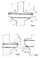
- FIG. 1 is a side view of the reinforced column subject to the invention according to design no. 1 with two stay cables
- Fig. 2 shows a front view of the same reinforced column
- Fig. 3 shows a side view of the reinforced column subject to the invention according to design no. 2 with four stay cables
- Fig. 4 shows a front view of the same reinforced column
- Fig. 5 shows a schematic cross section of the reinforced console of the armoured concrete column subject to the invention with console on both sides for the crane runway
- Fig. 6 shows a schematic cross section of the reinforced console of the armoured concrete column subject to the invention with a console for the crane runway on one side only
- Fig. 7 shows a partial cross section of an alternative design of the reinforced console.
- Figs. 1 and 2 show that the reinforced column 1 consists of an armoured concrete column section 2 equipped with a console 3 , on which beams 4 of the crane runway are mounted.
- the column section 2 is embedded in the foundation 5 .
- a hole is bored through the column section 2 , into which an anchor element 6 is embedded.
- it is made as an anchor tube 7 .
- the ends of the prestressed guys 8 are anchored into the anchor elements 6 by pulling the guy through the respective holes in the anchoring tube 7 , and in the downward direction the ends of the guys 8 are firmly fixed in the anchor sockets 9 that fit to the anchor tube 7 .
- the bearing surface of the anchor sockets 9 has such a shape to allow it to fit to the tube 7 perimeter shape-wise.
- the other end of the prestressed guy 8 is firmly anchored in the anchor 10 in the foundation 5 .
- the prestressed guy 8 is arranged angle-wise, but this is not conditional. It may also be arranged vertically.
- the reason of the arrangement of the guys 8 on the column element 2 is the reinforcement of column 1 in the direction of its axis.
- the hole with the anchor tube 7 is made in the upper part of the column section 2 taking advantage of the spot where the consoles 3 project from the section.
- Figs. 3 and 4 show the embodiment of the reinforced column 1 provided with four prestressed guys 8 . Afterwards the ends of both guys 8 are arranged in the anchor tube 7 on each side of the column section 2 ;from there the guys 8 go crossways to the anchors 10 in the foundation 5 .
- Fig. 5 shows that consoles 3 for crane runways are projecting from the armoured concrete column 1 on both sides, on which beams 4 for bridge crane tracks will be mounted. Both consoles 3 are interconnected by pre-bored ducts 12 , vertical to the column 1 axis.
- the prestressed clamping cables 13 or rather bars, go through these pre-bored ducts 12 . They are anchored on each side in the anchor sockets 15 with nuts. There is an anchor plate 14 under the anchor sockets.
- the upper prestressed clamping cable(s) 13 is led in the upper part of the consoles 3 where the lateral surface is vertical to the pre-bored duct 12 .
- the anchor plate 14 will easily fit to the side of the console 4 .
- the lower prestressed clamping cable 13 is led in the bottom part where the bottom wall of the console 3 joins the strut angle-wise: A recess 11 is made around the duct 12 with its front parallel to the axis of the column 1 . The anchor plate 14 will then easily lean against this front.
- Fig. 6 shows the reinforced (e.g. terminal) console column 1 also consisting of a strut from which, however, a console 3 for beam 4 projects, on which the tracks for the bridge crane are mounted on one side only.
- the console 3 and the adjacent part of the strut are interconnected by pre-bored ducts 12 , vertically to the axis of the column 1 .
- Prestressed clamping cables 13 or rather bars are led through these pre-bored ducts 12 . They are anchored on each side in the anchor sockets 15 with nuts. Under the anchor sockets there is the anchor plate 14 .
- a recess 11 is made in the oblique wall of the console 3 .
- Fig. 7 shows details of a solution in which the recess 11 referred to in the previous designs is not used for the lower post-tensioning cable, but a spacer 16 is inserted in between the anchor plate 14 , which is oblique and lies on the unmodified oblique lateral wall of the console 3 , and the socket 15 with a nut.
- the spacer corresponds on one side to the inclination of the oblique lateral wall of the console 3 and has a bearing surface for the anchor socket 14 on the other side parallel to the column axis.
- the concept of a reinforced console of a column is based on a surprising discovery that, in contrast to the theories acknowledged so far, it is not necessary to apply counter pressure in the same direction against the direction of the stress.
- console 3 is subject to downward stress and that the anticipated deforming fracture would go from the lower footing of the console crossways to the upper surface where the beam for crane tracks is mounted. So far theory would induce to anchor the cable on the oblique side of the console and to anchor its other end somewhere higher to the column so that the cable goes vertically to the fracture, i.e. against the direction of stress. It is obvious that such anchorage would be very demanding as far as the anchoring element on the column is concerned; it would require double boring of the column for ducts 12 in the bilateral console.
- the use of a non-typical steel device mounted to the armoured concrete column allows for boring with a standard drill, even in the oblique part of the column console.
- the minimum diameter of the borehole for one cable is 24 mm, being 40 mm for a cluster of cables.
- the borehole is widened to a minimum diameter of 80 mm at its end with a depth of 170 mm.
- the recess will allow for distributing the cables into the anchoring elements with permissible curvature.
- the directioning itself of the prestressed clamping cables 13 is achieved by beveling the bearing surface for the anchors on the anchor bearing plate and directioning the cable entry.
- Prestressing of each separate cable is carried out in 6 steps, starting at 0 kN and reaching the final value of 220 kN.
- the prestressing procedure is checked during each step in accordance with the stress-strain diagram of the prestressing jack where the value of the operating pressure of the jack corresponds to the prestress force introduced.
- the pressure is monitored with a pressure gauge.
- Individual steps of the whole prestressing procedure are entered into a control record where the value of elongation in mm is entered with the particular value of the operating pressure of the prestressing jack in MPa.
- the cable is re-tensioned twice with a 15-minute delay as a minimum.
- the overall elongation of the cable, the anchorage of the opposite anchor and cable rectification may vary from 35 to 55 mm with commonly used consoles. Subsequently the cable is carefully anchored at the side where tensioning takes place.
- Concrete compression from 50 ⁇ m/m to 90 ⁇ m/m is achieved by the above-mentioned method for standard types of consoles using three cables prestressed at 220 kN, depending on the particular value of the stress modulus of the column console concrete.
- the widened area of the borehole is injected with a constant-volume sealing compound.
- a grout hole is made in the anchor plate for this purpose.
Priority Applications (1)
| Application Number | Priority Date | Filing Date | Title |
|---|---|---|---|
| PL05466004T PL1705313T3 (pl) | 2004-03-24 | 2005-03-24 | Wzmocniona kolumna wspornikowa i sposób jej wytwarzania |
Applications Claiming Priority (2)
| Application Number | Priority Date | Filing Date | Title |
|---|---|---|---|
| CZ20040412A CZ300892B6 (cs) | 2004-03-24 | 2004-03-24 | Zpevnená konzola a zpusob jejího zpevnení |
| CZ20040413A CZ300893B6 (cs) | 2004-03-24 | 2004-03-24 | Zesílený sloup na zvýšenou nosnost a zpusob jeho výroby |
Publications (3)
| Publication Number | Publication Date |
|---|---|
| EP1705313A2 true EP1705313A2 (de) | 2006-09-27 |
| EP1705313A3 EP1705313A3 (de) | 2007-09-26 |
| EP1705313B1 EP1705313B1 (de) | 2009-12-02 |
Family
ID=36754277
Family Applications (1)
| Application Number | Title | Priority Date | Filing Date |
|---|---|---|---|
| EP05466004A Active EP1705313B1 (de) | 2004-03-24 | 2005-03-24 | Verstärkte Säule mit Konsole und dessen Herstellungsverfahen |
Country Status (4)
| Country | Link |
|---|---|
| EP (1) | EP1705313B1 (de) |
| AT (1) | ATE450680T1 (de) |
| DE (1) | DE602005018016D1 (de) |
| PL (1) | PL1705313T3 (de) |
Cited By (4)
| Publication number | Priority date | Publication date | Assignee | Title |
|---|---|---|---|---|
| WO2011110749A1 (en) * | 2010-03-12 | 2011-09-15 | Peikko Group Oy | Method in connection with a foundation for tower-like structures and a foundation for tower-like structures |
| CN103669895A (zh) * | 2012-09-24 | 2014-03-26 | 五冶集团上海有限公司 | 旧有钢结构工业厂房边柱变中柱在线快速改造方法 |
| CN111356812A (zh) * | 2017-10-26 | 2020-06-30 | 乌本产权有限公司 | 用于外部张紧塔区段的环形支架、混合塔的外部张紧系统、混合塔的塔段、混合塔、风能设施及用于混合塔的外部张紧系统的安装方法 |
| US20220178158A1 (en) * | 2020-12-07 | 2022-06-09 | Fuzhou University | Device and method for reinforcing round section wood beam by combination of prestressed frp sheet and high strength steel wire rope |
Citations (3)
| Publication number | Priority date | Publication date | Assignee | Title |
|---|---|---|---|---|
| GB1271024A (en) * | 1968-07-26 | 1972-04-19 | Ellon A G | Improvements in and relating to prefabricated buildings |
| SU931905A1 (ru) * | 1979-01-05 | 1982-05-30 | Предприятие П/Я Г-4743 | Устройство дл усилени надкрановой части колонны с консол ми |
| US20030000165A1 (en) * | 2001-06-27 | 2003-01-02 | Tadros Maher K. | Precast post-tensioned segmental pole system |
-
2005
- 2005-03-24 DE DE602005018016T patent/DE602005018016D1/de active Active
- 2005-03-24 EP EP05466004A patent/EP1705313B1/de active Active
- 2005-03-24 AT AT05466004T patent/ATE450680T1/de active
- 2005-03-24 PL PL05466004T patent/PL1705313T3/pl unknown
Patent Citations (3)
| Publication number | Priority date | Publication date | Assignee | Title |
|---|---|---|---|---|
| GB1271024A (en) * | 1968-07-26 | 1972-04-19 | Ellon A G | Improvements in and relating to prefabricated buildings |
| SU931905A1 (ru) * | 1979-01-05 | 1982-05-30 | Предприятие П/Я Г-4743 | Устройство дл усилени надкрановой части колонны с консол ми |
| US20030000165A1 (en) * | 2001-06-27 | 2003-01-02 | Tadros Maher K. | Precast post-tensioned segmental pole system |
Cited By (7)
| Publication number | Priority date | Publication date | Assignee | Title |
|---|---|---|---|---|
| WO2011110749A1 (en) * | 2010-03-12 | 2011-09-15 | Peikko Group Oy | Method in connection with a foundation for tower-like structures and a foundation for tower-like structures |
| CN103669895A (zh) * | 2012-09-24 | 2014-03-26 | 五冶集团上海有限公司 | 旧有钢结构工业厂房边柱变中柱在线快速改造方法 |
| CN103669895B (zh) * | 2012-09-24 | 2016-01-20 | 五冶集团上海有限公司 | 旧有钢结构工业厂房边柱变中柱在线快速改造方法 |
| CN111356812A (zh) * | 2017-10-26 | 2020-06-30 | 乌本产权有限公司 | 用于外部张紧塔区段的环形支架、混合塔的外部张紧系统、混合塔的塔段、混合塔、风能设施及用于混合塔的外部张紧系统的安装方法 |
| CN111356812B (zh) * | 2017-10-26 | 2022-07-08 | 乌本产权有限公司 | 用于外部张紧塔区段的环形支架、混合塔的外部张紧系统、混合塔的塔段、混合塔、风能设施及用于混合塔的外部张紧系统的安装方法 |
| US20220178158A1 (en) * | 2020-12-07 | 2022-06-09 | Fuzhou University | Device and method for reinforcing round section wood beam by combination of prestressed frp sheet and high strength steel wire rope |
| US11674323B2 (en) * | 2020-12-07 | 2023-06-13 | Fuzhou University | Device and method for reinforcing round section wood beam by combination of prestressed FRP sheet and high strength steel wire rope |
Also Published As
| Publication number | Publication date |
|---|---|
| PL1705313T3 (pl) | 2010-05-31 |
| ATE450680T1 (de) | 2009-12-15 |
| DE602005018016D1 (de) | 2010-01-14 |
| EP1705313A3 (de) | 2007-09-26 |
| EP1705313B1 (de) | 2009-12-02 |
Similar Documents
| Publication | Publication Date | Title |
|---|---|---|
| US11293183B2 (en) | Precast column base joint and construction method therefor | |
| US9765521B1 (en) | Precast reinforced concrete construction elements with pre-stressing connectors | |
| US3782061A (en) | Concrete building construction with improved post tensioning means | |
| US7765752B2 (en) | Anchor system with substantially longitudinally equal wedge compression | |
| KR100899372B1 (ko) | 기존 콘크리트 기초구조물로의 새로운 마이크로파일 두부의정착 방법 및 이를 이용한 기초 및 기둥 구조물의 보강공법 및 그 보강 구조 | |
| KR100890455B1 (ko) | 가시설 중량을 이용한 중력식 하중재하 장치, 이를 이용한프리플렉스 합성 거더의 제조 방법 및 장치 | |
| KR100589797B1 (ko) | 단순한 긴장으로 휨만을 가하는 대편심 프리스트레싱 방법과 장치 및 그를 이용한 psc보 | |
| KR102240257B1 (ko) | 타설압 저항성이 강화된 프리캐스트 벽체 | |
| KR101328045B1 (ko) | 프리캐스트 고성능 섬유시멘트 복합체를 이용한 철근 콘크리트 복합기둥공법 | |
| EP1705313B1 (de) | Verstärkte Säule mit Konsole und dessen Herstellungsverfahen | |
| CN110924522B (zh) | 一种钢筋混凝土梁与柱的钢板界面连接结构及连接方法 | |
| CN114658002B (zh) | 一种外置预应力钢支撑支护系统及其施工方法 | |
| JP4562631B2 (ja) | コンクリート構造物に於けるヒンジ部の補修構造 | |
| JP5439016B2 (ja) | 埋設型枠 | |
| EP3211156A1 (de) | Verfahren und anordnung zur verstärkung einer betonstruktur und bewehrte betonstruktur | |
| KR100725879B1 (ko) | 보강용거더를 이용한 교량 내하력 증진시스템 | |
| JP2017206844A (ja) | 耐震壁構造 | |
| KR200263281Y1 (ko) | 단면확대를 통한 구조물의 내진보강장치 | |
| KR101004221B1 (ko) | 포스트텐션으로 연속화된 와플형 슬래브 시스템 및 포스트텐션닝 방법 | |
| KR101151773B1 (ko) | 양단부에 프리스트레스미도입부를 설치한 프리스트레스트강합성거더와 이의 제작방법 | |
| KR20030006681A (ko) | 단면확대를 통한 구조물의 내진보강방법 및 그 장치 | |
| KR102197109B1 (ko) | 임플란트식 파일압입구가 이식된 슬래브단위체 및 이를 이용한 옹벽시공방법 | |
| KR20020059960A (ko) | 섬유혼입 콘크리트를 이용한 프리캐스트 바닥판 및 그가설공법 | |
| CN213805359U (zh) | 一种装配式框架预应力锚索支护结构 | |
| JPH093917A (ja) | 鋼製橋脚とフーチングとの結合部 |
Legal Events
| Date | Code | Title | Description |
|---|---|---|---|
| PUAI | Public reference made under article 153(3) epc to a published international application that has entered the european phase |
Free format text: ORIGINAL CODE: 0009012 |
|
| AK | Designated contracting states |
Kind code of ref document: A2 Designated state(s): AT BE BG CH CY CZ DE DK EE ES FI FR GB GR HU IE IS IT LI LT LU MC NL PL PT RO SE SI SK TR |
|
| AX | Request for extension of the european patent |
Extension state: AL BA HR LV MK YU |
|
| PUAL | Search report despatched |
Free format text: ORIGINAL CODE: 0009013 |
|
| AK | Designated contracting states |
Kind code of ref document: A3 Designated state(s): AT BE BG CH CY CZ DE DK EE ES FI FR GB GR HU IE IS IT LI LT LU MC NL PL PT RO SE SI SK TR |
|
| AX | Request for extension of the european patent |
Extension state: AL BA HR LV MK YU |
|
| AKX | Designation fees paid |
Designated state(s): AT BE BG CH CY CZ DE DK EE ES FI FR GB GR HU IE IS IT LI LT LU MC NL PL PT RO SE SI SK TR |
|
| 17P | Request for examination filed |
Effective date: 20080320 |
|
| R17P | Request for examination filed (corrected) |
Effective date: 20080702 |
|
| GRAP | Despatch of communication of intention to grant a patent |
Free format text: ORIGINAL CODE: EPIDOSNIGR1 |
|
| GRAS | Grant fee paid |
Free format text: ORIGINAL CODE: EPIDOSNIGR3 |
|
| GRAA | (expected) grant |
Free format text: ORIGINAL CODE: 0009210 |
|
| AK | Designated contracting states |
Kind code of ref document: B1 Designated state(s): AT BE BG CH CY CZ DE DK EE ES FI FR GB GR HU IE IS IT LI LT LU MC NL PL PT RO SE SI SK TR |
|
| REG | Reference to a national code |
Ref country code: GB Ref legal event code: FG4D |
|
| REG | Reference to a national code |
Ref country code: CH Ref legal event code: EP |
|
| REG | Reference to a national code |
Ref country code: IE Ref legal event code: FG4D |
|
| REF | Corresponds to: |
Ref document number: 602005018016 Country of ref document: DE Date of ref document: 20100114 Kind code of ref document: P |
|
| REG | Reference to a national code |
Ref country code: NL Ref legal event code: VDEP Effective date: 20091202 |
|
| PG25 | Lapsed in a contracting state [announced via postgrant information from national office to epo] |
Ref country code: FI Free format text: LAPSE BECAUSE OF FAILURE TO SUBMIT A TRANSLATION OF THE DESCRIPTION OR TO PAY THE FEE WITHIN THE PRESCRIBED TIME-LIMIT Effective date: 20091202 Ref country code: SE Free format text: LAPSE BECAUSE OF FAILURE TO SUBMIT A TRANSLATION OF THE DESCRIPTION OR TO PAY THE FEE WITHIN THE PRESCRIBED TIME-LIMIT Effective date: 20091202 Ref country code: LT Free format text: LAPSE BECAUSE OF FAILURE TO SUBMIT A TRANSLATION OF THE DESCRIPTION OR TO PAY THE FEE WITHIN THE PRESCRIBED TIME-LIMIT Effective date: 20091202 |
|
| LTIE | Lt: invalidation of european patent or patent extension |
Effective date: 20091202 |
|
| PG25 | Lapsed in a contracting state [announced via postgrant information from national office to epo] |
Ref country code: SI Free format text: LAPSE BECAUSE OF FAILURE TO SUBMIT A TRANSLATION OF THE DESCRIPTION OR TO PAY THE FEE WITHIN THE PRESCRIBED TIME-LIMIT Effective date: 20091202 Ref country code: CY Free format text: LAPSE BECAUSE OF FAILURE TO SUBMIT A TRANSLATION OF THE DESCRIPTION OR TO PAY THE FEE WITHIN THE PRESCRIBED TIME-LIMIT Effective date: 20091202 |
|
| REG | Reference to a national code |
Ref country code: PL Ref legal event code: T3 |
|
| REG | Reference to a national code |
Ref country code: SK Ref legal event code: T3 Ref document number: E 6886 Country of ref document: SK |
|
| PG25 | Lapsed in a contracting state [announced via postgrant information from national office to epo] |
Ref country code: RO Free format text: LAPSE BECAUSE OF FAILURE TO SUBMIT A TRANSLATION OF THE DESCRIPTION OR TO PAY THE FEE WITHIN THE PRESCRIBED TIME-LIMIT Effective date: 20091202 Ref country code: IS Free format text: LAPSE BECAUSE OF FAILURE TO SUBMIT A TRANSLATION OF THE DESCRIPTION OR TO PAY THE FEE WITHIN THE PRESCRIBED TIME-LIMIT Effective date: 20100402 Ref country code: PT Free format text: LAPSE BECAUSE OF FAILURE TO SUBMIT A TRANSLATION OF THE DESCRIPTION OR TO PAY THE FEE WITHIN THE PRESCRIBED TIME-LIMIT Effective date: 20100402 Ref country code: EE Free format text: LAPSE BECAUSE OF FAILURE TO SUBMIT A TRANSLATION OF THE DESCRIPTION OR TO PAY THE FEE WITHIN THE PRESCRIBED TIME-LIMIT Effective date: 20091202 Ref country code: NL Free format text: LAPSE BECAUSE OF FAILURE TO SUBMIT A TRANSLATION OF THE DESCRIPTION OR TO PAY THE FEE WITHIN THE PRESCRIBED TIME-LIMIT Effective date: 20091202 Ref country code: ES Free format text: LAPSE BECAUSE OF FAILURE TO SUBMIT A TRANSLATION OF THE DESCRIPTION OR TO PAY THE FEE WITHIN THE PRESCRIBED TIME-LIMIT Effective date: 20100313 Ref country code: BG Free format text: LAPSE BECAUSE OF FAILURE TO SUBMIT A TRANSLATION OF THE DESCRIPTION OR TO PAY THE FEE WITHIN THE PRESCRIBED TIME-LIMIT Effective date: 20100302 |
|
| PG25 | Lapsed in a contracting state [announced via postgrant information from national office to epo] |
Ref country code: BE Free format text: LAPSE BECAUSE OF FAILURE TO SUBMIT A TRANSLATION OF THE DESCRIPTION OR TO PAY THE FEE WITHIN THE PRESCRIBED TIME-LIMIT Effective date: 20091202 Ref country code: CZ Free format text: LAPSE BECAUSE OF FAILURE TO SUBMIT A TRANSLATION OF THE DESCRIPTION OR TO PAY THE FEE WITHIN THE PRESCRIBED TIME-LIMIT Effective date: 20091202 |
|
| PLBE | No opposition filed within time limit |
Free format text: ORIGINAL CODE: 0009261 |
|
| STAA | Information on the status of an ep patent application or granted ep patent |
Free format text: STATUS: NO OPPOSITION FILED WITHIN TIME LIMIT |
|
| PG25 | Lapsed in a contracting state [announced via postgrant information from national office to epo] |
Ref country code: MC Free format text: LAPSE BECAUSE OF NON-PAYMENT OF DUE FEES Effective date: 20100331 Ref country code: GR Free format text: LAPSE BECAUSE OF FAILURE TO SUBMIT A TRANSLATION OF THE DESCRIPTION OR TO PAY THE FEE WITHIN THE PRESCRIBED TIME-LIMIT Effective date: 20100303 |
|
| REG | Reference to a national code |
Ref country code: CH Ref legal event code: PL |
|
| 26N | No opposition filed |
Effective date: 20100903 |
|
| GBPC | Gb: european patent ceased through non-payment of renewal fee |
Effective date: 20100324 |
|
| REG | Reference to a national code |
Ref country code: FR Ref legal event code: ST Effective date: 20101130 |
|
| PG25 | Lapsed in a contracting state [announced via postgrant information from national office to epo] |
Ref country code: IE Free format text: LAPSE BECAUSE OF NON-PAYMENT OF DUE FEES Effective date: 20100324 Ref country code: FR Free format text: LAPSE BECAUSE OF NON-PAYMENT OF DUE FEES Effective date: 20100331 Ref country code: DK Free format text: LAPSE BECAUSE OF FAILURE TO SUBMIT A TRANSLATION OF THE DESCRIPTION OR TO PAY THE FEE WITHIN THE PRESCRIBED TIME-LIMIT Effective date: 20091202 |
|
| PG25 | Lapsed in a contracting state [announced via postgrant information from national office to epo] |
Ref country code: CH Free format text: LAPSE BECAUSE OF NON-PAYMENT OF DUE FEES Effective date: 20100331 Ref country code: LI Free format text: LAPSE BECAUSE OF NON-PAYMENT OF DUE FEES Effective date: 20100331 |
|
| PG25 | Lapsed in a contracting state [announced via postgrant information from national office to epo] |
Ref country code: IT Free format text: LAPSE BECAUSE OF FAILURE TO SUBMIT A TRANSLATION OF THE DESCRIPTION OR TO PAY THE FEE WITHIN THE PRESCRIBED TIME-LIMIT Effective date: 20091202 Ref country code: GB Free format text: LAPSE BECAUSE OF NON-PAYMENT OF DUE FEES Effective date: 20100324 |
|
| PG25 | Lapsed in a contracting state [announced via postgrant information from national office to epo] |
Ref country code: LU Free format text: LAPSE BECAUSE OF NON-PAYMENT OF DUE FEES Effective date: 20100324 Ref country code: HU Free format text: LAPSE BECAUSE OF FAILURE TO SUBMIT A TRANSLATION OF THE DESCRIPTION OR TO PAY THE FEE WITHIN THE PRESCRIBED TIME-LIMIT Effective date: 20100603 |
|
| PG25 | Lapsed in a contracting state [announced via postgrant information from national office to epo] |
Ref country code: TR Free format text: LAPSE BECAUSE OF FAILURE TO SUBMIT A TRANSLATION OF THE DESCRIPTION OR TO PAY THE FEE WITHIN THE PRESCRIBED TIME-LIMIT Effective date: 20091202 |
|
| REG | Reference to a national code |
Ref country code: DE Ref legal event code: R082 Ref document number: 602005018016 Country of ref document: DE Representative=s name: STAUDT IP LAW, DE |
|
| PGFP | Annual fee paid to national office [announced via postgrant information from national office to epo] |
Ref country code: PL Payment date: 20160323 Year of fee payment: 12 |
|
| PG25 | Lapsed in a contracting state [announced via postgrant information from national office to epo] |
Ref country code: PL Free format text: LAPSE BECAUSE OF NON-PAYMENT OF DUE FEES Effective date: 20170324 |
|
| PGFP | Annual fee paid to national office [announced via postgrant information from national office to epo] |
Ref country code: AT Payment date: 20230317 Year of fee payment: 19 |
|
| REG | Reference to a national code |
Ref country code: DE Ref legal event code: R082 Ref document number: 602005018016 Country of ref document: DE Representative=s name: SONNENBERG HARRISON PARTNERSCHAFT MBB PATENT- , DE |
|
| PGFP | Annual fee paid to national office [announced via postgrant information from national office to epo] |
Ref country code: AT Payment date: 20240318 Year of fee payment: 20 |
|
| PGFP | Annual fee paid to national office [announced via postgrant information from national office to epo] |
Ref country code: DE Payment date: 20240321 Year of fee payment: 20 Ref country code: SK Payment date: 20240301 Year of fee payment: 20 |