EP1705100A1 - Integrated transfer line for automotive steering system - Google Patents
Integrated transfer line for automotive steering system Download PDFInfo
- Publication number
- EP1705100A1 EP1705100A1 EP06005177A EP06005177A EP1705100A1 EP 1705100 A1 EP1705100 A1 EP 1705100A1 EP 06005177 A EP06005177 A EP 06005177A EP 06005177 A EP06005177 A EP 06005177A EP 1705100 A1 EP1705100 A1 EP 1705100A1
- Authority
- EP
- European Patent Office
- Prior art keywords
- transfer line
- secured
- tube
- port
- housing
- Prior art date
- Legal status (The legal status is an assumption and is not a legal conclusion. Google has not performed a legal analysis and makes no representation as to the accuracy of the status listed.)
- Withdrawn
Links
- 239000012530 fluid Substances 0.000 claims abstract description 59
- 238000007789 sealing Methods 0.000 claims description 23
- 238000005219 brazing Methods 0.000 claims description 21
- 238000005476 soldering Methods 0.000 claims description 21
- 238000003466 welding Methods 0.000 claims description 21
- 230000004044 response Effects 0.000 description 4
- 229910052782 aluminium Inorganic materials 0.000 description 3
- XAGFODPZIPBFFR-UHFFFAOYSA-N aluminium Chemical compound [Al] XAGFODPZIPBFFR-UHFFFAOYSA-N 0.000 description 3
- XEEYBQQBJWHFJM-UHFFFAOYSA-N Iron Chemical compound [Fe] XEEYBQQBJWHFJM-UHFFFAOYSA-N 0.000 description 2
- 229910000831 Steel Inorganic materials 0.000 description 2
- 230000008878 coupling Effects 0.000 description 2
- 238000010168 coupling process Methods 0.000 description 2
- 238000005859 coupling reaction Methods 0.000 description 2
- 238000001125 extrusion Methods 0.000 description 2
- 230000007246 mechanism Effects 0.000 description 2
- 229910052751 metal Inorganic materials 0.000 description 2
- 239000002184 metal Substances 0.000 description 2
- 239000010959 steel Substances 0.000 description 2
- FYYHWMGAXLPEAU-UHFFFAOYSA-N Magnesium Chemical compound [Mg] FYYHWMGAXLPEAU-UHFFFAOYSA-N 0.000 description 1
- HCHKCACWOHOZIP-UHFFFAOYSA-N Zinc Chemical compound [Zn] HCHKCACWOHOZIP-UHFFFAOYSA-N 0.000 description 1
- 230000008859 change Effects 0.000 description 1
- 230000006835 compression Effects 0.000 description 1
- 238000007906 compression Methods 0.000 description 1
- 238000009434 installation Methods 0.000 description 1
- 229910052742 iron Inorganic materials 0.000 description 1
- 239000007788 liquid Substances 0.000 description 1
- 229910052749 magnesium Inorganic materials 0.000 description 1
- 239000011777 magnesium Substances 0.000 description 1
- 230000014759 maintenance of location Effects 0.000 description 1
- 150000002739 metals Chemical class 0.000 description 1
- 238000000034 method Methods 0.000 description 1
- 230000000704 physical effect Effects 0.000 description 1
- 239000013589 supplement Substances 0.000 description 1
- 229910052725 zinc Inorganic materials 0.000 description 1
- 239000011701 zinc Substances 0.000 description 1
Images




Classifications
-
- B—PERFORMING OPERATIONS; TRANSPORTING
- B62—LAND VEHICLES FOR TRAVELLING OTHERWISE THAN ON RAILS
- B62D—MOTOR VEHICLES; TRAILERS
- B62D5/00—Power-assisted or power-driven steering
- B62D5/06—Power-assisted or power-driven steering fluid, i.e. using a pressurised fluid for most or all the force required for steering a vehicle
- B62D5/062—Details, component parts
Definitions
- the present invention relates generally to automotive steering system. More particularly, it pertains to apparatus for hydraulically sealing and connecting transfer lines to a tube and housing.
- a power-assisted, rack and pinion steering system for automotive applications includes a steering shaft controlled manually by the vehicle operator by rotating the vehicle's steering wheel.
- the steering shaft is connected through a flexible coupling to a pinion gear, which is driveably engaged with a rack located in a relatively thick walled tube.
- the rack extends laterally from a housing to a mechanism that steers the vehicle's wheels.
- the tube also contains a hydraulic double-acting piston, which is secured to the rack.
- a piston moves in a cylinder located in the tube in response to differential pressure across the piston.
- a control valve alternately pressurizes and vents the opposite faces of the cylinder in response to rotation of the steering wheel and pinion gear.
- a net hydraulic pressure force produced on the piston assists the vehicle operator to steer the wheels by adding to the force on the rack applied manually by the vehicle operator. In this way, the operator's effort and the degree to which the steering wheel is rotated in order to produce a desired change in direction are reduced.
- Transfer lines carry pressurized hydraulic fluid from the housing to the cylinder located in the tube.
- the housing is formed of cast aluminum, but the tube and transfer lines are of steel.
- the physical property differences and strength dissimilarities of the metals add to the complicity of the connections at each end of the transfer lines.
- the present invention concerns an apparatus for connecting pressure transfer lines to the outer surface of the main rack tube either through a direct connection in which the lines are connected to the tube's outer surface by brazing, soldering or welding, or indirectly using a fitting, which is attached directly to the outer surface of the main rack tube by brazing, soldering or welding and provides a sealed slip attachment with the transfer line.
- the opposite end of the transfer lines are connected to the housing either using a threaded insert engaged with screw threads formed in the housing wall, an insert molded in place, or a retainer plate attached to the housing.
- the transfer lines are connected to the insert or retaining plate by a brazed, soldered or welded connection, each attachment providing an integral hydraulic seal.
- An apparatus for carrying hydraulic fluid in a power assisted automotive steering system, includes a tube having a tube wall formed with a first port that extends though a thickness of the tube wall.
- a housing includes a wall formed with a second port extending though a thickness of the housing wall.
- a retainer is secured to the housing.
- a fluid transfer line includes a first surface that contacts an outer surface of the tube, is formed with a passage communicating with the first port, is sealed against fluid flow past the first surface, and is secured to an outer surface of the tube.
- a second surface contacting the retainer is formed with a passage communicating with the second port, is sealed against fluid flow past the second surface, and is secured to the housing by the retainer.
- FIG. 1A is an external isometric view of a power-assisted rack and pinion steering mechanism for an automotive vehicle.
- the vehicle operator rotates the steering shaft 10 about axis 12 by turning the vehicle's steering wheel.
- the steering shaft 10 is driveably connected through a flexible coupling 14 to a pinion gear, located in a housing 18, which also contains a fluid control valve.
- the pinion gear is driveably engaged with a rack located in a relatively thick walled tube 20, which extends transversely from housing 18 and also contains a hydraulic double acting piston secured to the rack.
- the rack moves in opposite linear directions along axis 16 in response to rotation of the steering wheel and pinion gear in opposite angular directions.
- the tube 20 and housing 18 are supported on the frame of the vehicle by mounting brackets 22, 24.
- the piston located in tube 20 and secured to the rack, is actuated by pressurized hydraulic fluid supplied to a cylinder located on opposite sides of the piston.
- a transfer line 26 carries pressurized fluid to one side of the piston; transfer line 28 carries pressurized hydraulic fluid to the other side of the piston.
- transfer line 26 is directly connected at 30 to the outer surface of tube 20, and transfer line 28 is directly connected at 32 to the outer surface of the tube 20.
- the opposite ends of transfer lines 26, 28 are each connected to the wall 46 of valve-pinion housing 18 by an insert 36, which is threaded or molded in place into the housing wall.
- the axial outer end of transfer line 26 is formed with a bend 38 such that the end of the line is substantially perpendicular to the outer surface of tube 20.
- the axial outer end of transfer line 28 is formed with a bend 40 so that the transfer line is substantially perpendicular to the outer surface of tube 20.
- Figure 1B shows an end of each transfer line 26, 28 connected to housing 18 using inserts 36' that are cast integrally with the housing wall 46.
- Figure 1C shows an end of each a transfer line 26, 28 fitted in a respective boss on the wall 46 on the housing 18, the bosses being drilled to receive the ends of the transfer lines without inserts.
- transfer lines 42, 44 which extend transversely from the valve-pinion gear housing 18, are secured to the outer surface of tube 20 using weld fittings 48, 50, respectively.
- the opposite axial end of transfer lines 42, 44 is secured by a hydraulically sealed connection to the wall 46 of housing 18.
- the bend 38 at the end of transfer line 26 positions the line substantially perpendicular to the outer surface of tube 20 such that the transfer line communicates sufficiently with a port 61 that passes through the wall thickness of the tube to allow fluid flow between the tube and the transfer line.
- the axial end of the transfer line 26 is formed with a flared flange 60, which is seated on the outer surface of tube 20 and secured to that surface by soldering, brazing or welding. This connection also seals against the flow of hydraulic fluid between the tube 20 and line 26.
- Figure 3B shows a transfer line 26 formed with a flange, preferably formed by axially compressing the tube to produce an overlapping flared flange 62, which is seated on the outer surface of tube 20 and secured to tube 20 by soldering, brazing or welding.
- Transfer line 26 communicates sufficiently with port 61 to allow fluid flow between the tube 20 and the transfer line.
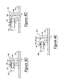
- Figure 4A illustrates a 90-degree weld fitting 48 secured to the outer surface of tube 20 by soldering, brazing or welding.
- Fitting 48 includes a radial passage 66, which communicates with port 61 and with a lateral passage 64.
- Transfer line 42 is inserted in the lateral passage 64, to which it is secured at 68 by soldering, brazing or welding.
- a liquid sealer may be applied around the periphery of the transfer line 42 where is contacts at 68 the outer surface 70 of fitting 48 to seal against fluid flow and to enhance the seal provided by a connection between transfer line 42 and fitting 48 made by soldering, brazing or welding.
- Transfer line 42 engages the inner surface of lateral passage 64 preferably with an interference fit.
- Figure 4B illustrates a weld fitting 48' that is secured to the outer surface of tube 20 by welding, brazing or soldering.
- a lateral arm 72 of fitting 48' is formed during a swedging operation with an angular recess 74.
- Transfer line 42 is inserted in the lateral passage 64 and may be sealed and secured to fitting 48' by swedging the fitting in the vicinity of recess 74 so that it engages the transfer line with an interference fit.
- the swedged connection is an alternative or a supplement to securing the transfer line 42 to fitting 48' by soldering, brazing or welding.
- Fitting 48" shown in Figure 4C is secured into the outer surface of tube 20 by soldering, brazing or welding.
- Fitting 48" includes a lateral passage 68, formed with a recess 80 containing an 0-ring 82 or a comparable sealing device.
- Transfer line 42 is inserted into the lateral passage 68 and engages the 0-ring 82 and the wall of the lateral passage with an interference fit, thereby sealing the passage against the flow of hydraulic fluid and securing the transfer line to fitting 48".
- the weld fitting 50 shown in Figure 4D is secured to the outer surface of tube 20 by soldering, brazing or welding.
- the fitting 50 is formed with an enlarged lateral passage 68', whose diameter is sized to receive transfer line 44 and the 0-ring 84, located in the recess 86 formed on the outer surface of the transfer line 44. In this arrangement, an interference fit is produced between the surface of passage 68' and the outer radial surface of O-ring 84.
- Figure 4E shows yet another configuration of a transfer line 44 and a weld fitting 50', which is secured to the outer surface of tube 20 by soldering, brazing or welding.
- a portion of the length of the lateral passage 68" is formed with larger diameter surface 90, which is sized to receive a sealing device such as an 0-ring 92.
- a portion of the length of transfer line 44' is crimped to form an overlapping flange 94 that extends radially outward from the surface of transfer line 44' and is spaced axially from the nearest end of the transfer line.
- a terminal length of the transfer line 44', inserted in passage 68" holds 0-ring 92 in position between flange 94 and the step between surface 90 and lateral passage 68".
- flange 94 frictionally engages surface 90 with a sufficient interference fit to maintain preloaded compression in the sealing device (92), thereby sealing the connection against the passage of hydraulic fluid and securing the transfer line 44' to the weld fitting 50'.
- the flange also prevents extrusion of the seal 84.
- wall 46 of housing 18 is relatively thick in relation to the wall thickness of the transfer lines 26, 28, 42,46 and of the tube 20, and it is formed preferably of aluminum, other cast metal including, but not limited to zinc, iron, magnesium, whereas the transfer lines and tube are of steel.
- a retainer insert 36 has external screw threads that engage screw threads tapped into the wall 46 of housing 18, and a central passage 102 communicating with passage 104 formed in housing wall 46 to permit fluid flow between transfer line 28 and housing 18.
- a length of transfer line 28 near its end is flared radially outward forming a flange surface that is secured to insert 36 by welding, soldering or brazing.
- the head of inserts 36 are each formed with a hexagonal surface to facilitate threading them into wall 46.
- the outer surface of the insert can either extend be located outward from the surface of the wall, or flush with the wall surface, or below the wall surface.
- an insert 36' can be molded in place without having to be machined and screwed into the housing wall 46.
- Figure 5B shows another connection for securing transfer line 28' to housing wall 46 using a threaded retainer insert 36' formed with external screw threads.
- the threaded insert 36' is formed with a stepped central passage 108, communicating with the passage 104 in housing wall 46, to permit fluid flow between transfer line 28 and housing 18.
- the outer end of the insert has an enlarged surface 110, sized to receive transfer line 28', which is inserted into the insert and is secured to the insert by welding, soldering or brazing at a fillet 109.
- each insert 36' can be molded in place without having to be machined and screwed into the housing wall 46.
- the outer surface of the insert can either extend be located outward from the surface of the wall, or flush with the wall surface, or below the wall surface.
- the threaded retainer insert 36' is secured to housing wall 46 by the engagement of screw threads on its outer surface with the internal screw threads tapped into the wall.
- the threaded insert 36' is formed with a stepped central passage 108, communicating with the passage 104 in housing wall 46, to permit fluid flow between transfer line 28" and housing 18.
- a portion of the length of transfer line 28" is crimped to form an overlapping radial flange 112 near the axial end of the transfer line, and the length of the tube between the flange and transfer line end is inserted into the enlarge passage 110.
- each insert 36' can be molded in place without having to be machined and screwed into the housing wall 46.
- the outer surface of the insert can either extend outward from the surface of the wall, or be located flush with the wall surface, or below the wall surface.
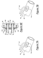
- Figures 6A-6C show alternate connections for securing a transfer line 42, 44 to housing wall 46 using a retention plate 114.
- the housing wall 46 is formed with a stepped central opening extending through the thickness of the wall.
- An intermediate surface 116 of the opening is located between the hydraulic passage 104 and the largest diameter portion 118 formed in the thickness of the wall.
- a portion of the length of transfer line 42 is crimped to form an overlapping radial flange 122 near the axial end of the transfer line, and the length of the tube between the flange and transfer line end is inserted into the opening portions 116, 118.
- a sealing device 120 such as an O-ring, is fitted among a step in the housing wall 46, the flange 122, and the length 131 of the transfer line that extends between the flange and the line end.
- the retainer plate 114 is formed with an open central hole through its thickness so that the plate can be moved along the transfer line into engagement with the outer surface of the flange 122 and into contact with the housing outer surface.
- a threaded attachment or attachments 124 secure plate 114 to the housing wall 46.
- plate 114 can be deleted, and each the lines is secured to the wall 46 using the flange 122 fitted into the opening 118.
- the wall housing 46' is formed with a single opening 126, which extends through the housing wall and is formed with an internal recess 128, fitted with a sealing device such as an 0-ring 130.
- Retainer plate 114 is secured to the transfer line 42' by welding, brazing or soldering forming a fillet 138 at an axial location that is spaced from an end of the tube.
- Fasteners 124 secure retainer plate 114 to the housing wall 46. This provides a length of transfer line 42' that is inserted into opening 126, overlapping the radial inner surface of the sealing device 130 and compressing the sealing device to provide a hydraulic seal between opening 126 and transfer line 42'.
- a plate 114' secured by attachments 124 to the wall 46, may be joggled over a flange 140 formed on each transfer line 42"'.
- Recess 128 contains an 0-ring 130, or another sealing device.
- each transfer line 42, 44 is formed with a flared flange 122, and secured to the wall 46 by a single retainer plate 114".
- the wall 46 is formed with recesses 128, each recess containing an O-ring 130, or another sealing device.
- the plate retainers 114, 114', 114" allow the transfer lines to rotate, thereby facilitating their installation and assembly.
- housing wall 46 is formed with a single opening 129 extending entirely through the thickness of the wall.
- the transfer line 42" is formed with a recess 132, which is spaced axially from the end 134 of the transfer line.
- the recess 132 is sized to receive a sealing device 136, such as an 0-ring.
- Retainer plate 114 is secured to the transfer line 42" by welding, brazing or soldering forming a fillet 138 at an axial location that is spaced from an end of the tube.
- Retainer plate 114 is secured by fasteners 124 to the outer surface of the housing wall 46 such that the adjacent faces of the retainer plate (114) and housing wall 46 are in mutual contact.
- the transfer line 42" is moved into engagement with housing wall 46 such that the sealing device 136 engages opening 129 with an interference fit that compresses the seal 136, thereby providing a fluid type connection between the opening 129 and the transfer line 42".
- plate 114 can be deleted, and each the lines is then secured to the wall 46" using an interference fit between the outer surface of the line and the opening 129.
- Figure 7A is an external view of a housing 10 showing transfer lines 42, 44 secured by retainer plates 144 using a single hex headed attachment integrated into a single retainer plate 114', as shown Figure 7B.
Landscapes
- Engineering & Computer Science (AREA)
- Chemical & Material Sciences (AREA)
- Combustion & Propulsion (AREA)
- Transportation (AREA)
- Mechanical Engineering (AREA)
- Power Steering Mechanism (AREA)
Abstract
Description
- The present invention relates generally to automotive steering system. More particularly, it pertains to apparatus for hydraulically sealing and connecting transfer lines to a tube and housing.
- A power-assisted, rack and pinion steering system for automotive applications includes a steering shaft controlled manually by the vehicle operator by rotating the vehicle's steering wheel. The steering shaft is connected through a flexible coupling to a pinion gear, which is driveably engaged with a rack located in a relatively thick walled tube. The rack extends laterally from a housing to a mechanism that steers the vehicle's wheels.
- The tube also contains a hydraulic double-acting piston, which is secured to the rack. A piston moves in a cylinder located in the tube in response to differential pressure across the piston. A control valve alternately pressurizes and vents the opposite faces of the cylinder in response to rotation of the steering wheel and pinion gear. As the rack moves in opposite linear directions along the tube in response to rotation of the steering wheel, a net hydraulic pressure force produced on the piston assists the vehicle operator to steer the wheels by adding to the force on the rack applied manually by the vehicle operator. In this way, the operator's effort and the degree to which the steering wheel is rotated in order to produce a desired change in direction are reduced.
- Transfer lines carry pressurized hydraulic fluid from the housing to the cylinder located in the tube. Generally the housing is formed of cast aluminum, but the tube and transfer lines are of steel. The physical property differences and strength dissimilarities of the metals add to the complicity of the connections at each end of the transfer lines.
- There is a long felt need in steering gear design for an efficient, low cost technique to connect the transfer lines to the outer surface of the tube without use of weld stud adapters attached to the rack tube and providing a screw-in attachment to the transfer lines. It is desired that the transfer lines be connected to the aluminum housing using a screw-in attachment, or a metallic bond to a threaded insert, or a slip attachment that is hydraulically sealed.
- The present invention concerns an apparatus for connecting pressure transfer lines to the outer surface of the main rack tube either through a direct connection in which the lines are connected to the tube's outer surface by brazing, soldering or welding, or indirectly using a fitting, which is attached directly to the outer surface of the main rack tube by brazing, soldering or welding and provides a sealed slip attachment with the transfer line.
- The opposite end of the transfer lines are connected to the housing either using a threaded insert engaged with screw threads formed in the housing wall, an insert molded in place, or a retainer plate attached to the housing. In either case, the transfer lines are connected to the insert or retaining plate by a brazed, soldered or welded connection, each attachment providing an integral hydraulic seal.
- These connections provide simplicity of assembly, allow the transfer lines to be installed during the assembly of the tube to the housing, and easily accommodate diverse applications because of the improved clearance space provided.
- An apparatus according to this invention for carrying hydraulic fluid in a power assisted automotive steering system, includes a tube having a tube wall formed with a first port that extends though a thickness of the tube wall. A housing includes a wall formed with a second port extending though a thickness of the housing wall. A retainer is secured to the housing. A fluid transfer line includes a first surface that contacts an outer surface of the tube, is formed with a passage communicating with the first port, is sealed against fluid flow past the first surface, and is secured to an outer surface of the tube. A second surface contacting the retainer is formed with a passage communicating with the second port, is sealed against fluid flow past the second surface, and is secured to the housing by the retainer.
- The above, as well as other advantages of the present invention, will become readily apparent to those skilled in the art from the following detailed description of a preferred embodiment when considered in the light of the accompanying drawings in which:
- Figs. 1A-1C
- are isometric views of a steering gear assembly for an automotive vehicle showing transfer lines secured to a tube and various connections to a housing at the opposite end of the transfer lines;
- Figure 2
- is an isometric view of a steering gear assembly for an automotive vehicle showing transfer lines secured to a tube in accordance with the present invention;
- Figs. 3A and 3B
- are cross sections taken at plane 3 of Figure 1;
- Figs. 4A-4E
- are cross sections taken at plane 4 of Figure 2;
- Figures 5A-5C
- are cross sections taken at plane 5 of Figure 1;
- Figures 6A-6E
- are cross sections taken at plane 6 of Figure 2;
- Figure 7A
- is an external view of a housing showing transfer lines secured by retainer plates; and
- Figure 7B
- is a view showing the transfer lines of Figure 7 secured by a single retainer plate.
- Figure 1A is an external isometric view of a power-assisted rack and pinion steering mechanism for an automotive vehicle. The vehicle operator rotates the
steering shaft 10 aboutaxis 12 by turning the vehicle's steering wheel. Thesteering shaft 10 is driveably connected through aflexible coupling 14 to a pinion gear, located in ahousing 18, which also contains a fluid control valve. The pinion gear is driveably engaged with a rack located in a relatively thickwalled tube 20, which extends transversely fromhousing 18 and also contains a hydraulic double acting piston secured to the rack. The rack moves in opposite linear directions alongaxis 16 in response to rotation of the steering wheel and pinion gear in opposite angular directions. Thetube 20 andhousing 18 are supported on the frame of the vehicle by mountingbrackets - The piston, located in
tube 20 and secured to the rack, is actuated by pressurized hydraulic fluid supplied to a cylinder located on opposite sides of the piston. Atransfer line 26 carries pressurized fluid to one side of the piston;transfer line 28 carries pressurized hydraulic fluid to the other side of the piston. As soon in Figure 1A,transfer line 26 is directly connected at 30 to the outer surface oftube 20, andtransfer line 28 is directly connected at 32 to the outer surface of thetube 20. The opposite ends oftransfer lines wall 46 of valve-pinion housing 18 by aninsert 36, which is threaded or molded in place into the housing wall. The axial outer end oftransfer line 26 is formed with abend 38 such that the end of the line is substantially perpendicular to the outer surface oftube 20. Similarly, the axial outer end oftransfer line 28 is formed with abend 40 so that the transfer line is substantially perpendicular to the outer surface oftube 20. - Figure 1B shows an end of each
transfer line housing 18 using inserts 36' that are cast integrally with thehousing wall 46. Figure 1C shows an end of each atransfer line wall 46 on thehousing 18, the bosses being drilled to receive the ends of the transfer lines without inserts. - Turning now to Figure 2,
transfer lines pinion gear housing 18, are secured to the outer surface oftube 20 usingweld fittings transfer lines wall 46 ofhousing 18. - Referring now to Figures 3A and 3B, the
bend 38 at the end oftransfer line 26 positions the line substantially perpendicular to the outer surface oftube 20 such that the transfer line communicates sufficiently with aport 61 that passes through the wall thickness of the tube to allow fluid flow between the tube and the transfer line. The axial end of thetransfer line 26 is formed with a flaredflange 60, which is seated on the outer surface oftube 20 and secured to that surface by soldering, brazing or welding. This connection also seals against the flow of hydraulic fluid between thetube 20 andline 26. - Figure 3B shows a
transfer line 26 formed with a flange, preferably formed by axially compressing the tube to produce an overlapping flaredflange 62, which is seated on the outer surface oftube 20 and secured totube 20 by soldering, brazing or welding.Transfer line 26 communicates sufficiently withport 61 to allow fluid flow between thetube 20 and the transfer line. - Figure 4A illustrates a 90-degree weld fitting 48 secured to the outer surface of
tube 20 by soldering, brazing or welding. Fitting 48 includes aradial passage 66, which communicates withport 61 and with alateral passage 64.Transfer line 42 is inserted in thelateral passage 64, to which it is secured at 68 by soldering, brazing or welding. A liquid sealer may be applied around the periphery of thetransfer line 42 where is contacts at 68 theouter surface 70 of fitting 48 to seal against fluid flow and to enhance the seal provided by a connection betweentransfer line 42 and fitting 48 made by soldering, brazing or welding.Transfer line 42 engages the inner surface oflateral passage 64 preferably with an interference fit. - Figure 4B illustrates a weld fitting 48' that is secured to the outer surface of
tube 20 by welding, brazing or soldering. Alateral arm 72 of fitting 48' is formed during a swedging operation with anangular recess 74.Transfer line 42 is inserted in thelateral passage 64 and may be sealed and secured to fitting 48' by swedging the fitting in the vicinity ofrecess 74 so that it engages the transfer line with an interference fit. The swedged connection is an alternative or a supplement to securing thetransfer line 42 to fitting 48' by soldering, brazing or welding. - The weld fitting 48" shown in Figure 4C is secured into the outer surface of
tube 20 by soldering, brazing or welding. Fitting 48" includes alateral passage 68, formed with arecess 80 containing an 0-ring 82 or a comparable sealing device.Transfer line 42 is inserted into thelateral passage 68 and engages the 0-ring 82 and the wall of the lateral passage with an interference fit, thereby sealing the passage against the flow of hydraulic fluid and securing the transfer line to fitting 48". - The weld fitting 50 shown in Figure 4D is secured to the outer surface of
tube 20 by soldering, brazing or welding. The fitting 50 is formed with an enlarged lateral passage 68', whose diameter is sized to receivetransfer line 44 and the 0-ring 84, located in therecess 86 formed on the outer surface of thetransfer line 44. In this arrangement, an interference fit is produced between the surface of passage 68' and the outer radial surface of O-ring 84. - Figure 4E shows yet another configuration of a
transfer line 44 and a weld fitting 50', which is secured to the outer surface oftube 20 by soldering, brazing or welding. A portion of the length of thelateral passage 68" is formed withlarger diameter surface 90, which is sized to receive a sealing device such as an 0-ring 92. A portion of the length of transfer line 44' is crimped to form an overlappingflange 94 that extends radially outward from the surface of transfer line 44' and is spaced axially from the nearest end of the transfer line. A terminal length of the transfer line 44', inserted inpassage 68", holds 0-ring 92 in position betweenflange 94 and the step betweensurface 90 andlateral passage 68". The radial outer surface offlange 94 frictionally engagessurface 90 with a sufficient interference fit to maintain preloaded compression in the sealing device (92), thereby sealing the connection against the passage of hydraulic fluid and securing the transfer line 44' to the weld fitting 50'. The flange also prevents extrusion of theseal 84. - Referring now to Figures 5A-5C,
wall 46 ofhousing 18 is relatively thick in relation to the wall thickness of the transfer lines 26, 28, 42,46 and of thetube 20, and it is formed preferably of aluminum, other cast metal including, but not limited to zinc, iron, magnesium, whereas the transfer lines and tube are of steel. - As Figure 5A shows, a
retainer insert 36 has external screw threads that engage screw threads tapped into thewall 46 ofhousing 18, and acentral passage 102 communicating withpassage 104 formed inhousing wall 46 to permit fluid flow betweentransfer line 28 andhousing 18. A length oftransfer line 28 near its end is flared radially outward forming a flange surface that is secured to insert 36 by welding, soldering or brazing. As Figure 1A shows, the head ofinserts 36 are each formed with a hexagonal surface to facilitate threading them intowall 46. The outer surface of the insert can either extend be located outward from the surface of the wall, or flush with the wall surface, or below the wall surface. Alternatively, as FIGURE 1B shows, an insert 36' can be molded in place without having to be machined and screwed into thehousing wall 46. - Figure 5B shows another connection for securing transfer line 28' to
housing wall 46 using a threaded retainer insert 36' formed with external screw threads. The threaded insert 36' is formed with a steppedcentral passage 108, communicating with thepassage 104 inhousing wall 46, to permit fluid flow betweentransfer line 28 andhousing 18. The outer end of the insert has anenlarged surface 110, sized to receive transfer line 28', which is inserted into the insert and is secured to the insert by welding, soldering or brazing at afillet 109. As shown in Figure 1B, each insert 36' can be molded in place without having to be machined and screwed into thehousing wall 46. The outer surface of the insert can either extend be located outward from the surface of the wall, or flush with the wall surface, or below the wall surface. - In the transfer line connection of Figure 5C, the threaded retainer insert 36' is secured to
housing wall 46 by the engagement of screw threads on its outer surface with the internal screw threads tapped into the wall. The threaded insert 36' is formed with a steppedcentral passage 108, communicating with thepassage 104 inhousing wall 46, to permit fluid flow betweentransfer line 28" andhousing 18. A portion of the length oftransfer line 28" is crimped to form an overlappingradial flange 112 near the axial end of the transfer line, and the length of the tube between the flange and transfer line end is inserted into the enlargepassage 110. Thetransfer line 28" is inserted into thepassage 110,flange 112 contacts the adjacent face of the threaded insert 36', and the flange is secured to the adjacent face of insert 36' at 113 by welding, soldering or brazing. As shown in Figure 1B, each insert 36' can be molded in place without having to be machined and screwed into thehousing wall 46. The outer surface of the insert can either extend outward from the surface of the wall, or be located flush with the wall surface, or below the wall surface. - Figures 6A-6C show alternate connections for securing a
transfer line housing wall 46 using aretention plate 114. - In the connection of Figure 6A, the
housing wall 46 is formed with a stepped central opening extending through the thickness of the wall. Anintermediate surface 116 of the opening is located between thehydraulic passage 104 and thelargest diameter portion 118 formed in the thickness of the wall. A portion of the length oftransfer line 42 is crimped to form an overlappingradial flange 122 near the axial end of the transfer line, and the length of the tube between the flange and transfer line end is inserted into the openingportions sealing device 120, such as an O-ring, is fitted among a step in thehousing wall 46, theflange 122, and thelength 131 of the transfer line that extends between the flange and the line end. Theretainer plate 114 is formed with an open central hole through its thickness so that the plate can be moved along the transfer line into engagement with the outer surface of theflange 122 and into contact with the housing outer surface. A threaded attachment orattachments 124secure plate 114 to thehousing wall 46. - Producing a preloaded fit among 0-
ring 120,wall 46, andtransfer line 42 by compressing the 0-ring seals the connection. The flare orflange 122 also prevents extrusion of theseal device 120. - When the transfer lines 42, 44 are straight, as shown in Figure 2,
plate 114 can be deleted, and each the lines is secured to thewall 46 using theflange 122 fitted into theopening 118. - In the transfer line connection of Figure 6B, the wall housing 46' is formed with a
single opening 126, which extends through the housing wall and is formed with aninternal recess 128, fitted with a sealing device such as an 0-ring 130.Retainer plate 114 is secured to the transfer line 42' by welding, brazing or soldering forming afillet 138 at an axial location that is spaced from an end of the tube.Fasteners 124secure retainer plate 114 to thehousing wall 46. This provides a length of transfer line 42' that is inserted intoopening 126, overlapping the radial inner surface of thesealing device 130 and compressing the sealing device to provide a hydraulic seal betweenopening 126 and transfer line 42'. - Alternatively, as shown in Fig 6D, a
plate 114', secured byattachments 124 to thewall 46, may be joggled over aflange 140 formed on eachtransfer line 42"'. Recess 128 contains an 0-ring 130, or another sealing device. - In Figure 6E each
transfer line flange 122, and secured to thewall 46 by asingle retainer plate 114". Thewall 46 is formed withrecesses 128, each recess containing an O-ring 130, or another sealing device. Theplate retainers - Referring to Figure 6C,
housing wall 46 is formed with asingle opening 129 extending entirely through the thickness of the wall. Thetransfer line 42" is formed with arecess 132, which is spaced axially from theend 134 of the transfer line. Therecess 132 is sized to receive asealing device 136, such as an 0-ring.Retainer plate 114 is secured to thetransfer line 42" by welding, brazing or soldering forming afillet 138 at an axial location that is spaced from an end of the tube.Retainer plate 114 is secured byfasteners 124 to the outer surface of thehousing wall 46 such that the adjacent faces of the retainer plate (114) andhousing wall 46 are in mutual contact. Thetransfer line 42" is moved into engagement withhousing wall 46 such that thesealing device 136 engages opening 129 with an interference fit that compresses theseal 136, thereby providing a fluid type connection between theopening 129 and thetransfer line 42". - When the
transfer lines 42", 44" are straight, as shown in Figure 2,plate 114 can be deleted, and each the lines is then secured to thewall 46" using an interference fit between the outer surface of the line and theopening 129. - Figure 7A is an external view of a
housing 10 showingtransfer lines single retainer plate 114', as shown Figure 7B. - In accordance with the provisions of the patent statutes, the present invention has been described in what is considered to represent its preferred embodiment. However, it should be noted that the invention can be practiced otherwise than as specifically illustrated and described without departing from its spirit or scope.
Claims (16)
- Apparatus for carrying hydraulic fluid in an automotive steering system, comprising:a tube including a tube wall formed with a first port extending though a thickness of the tube wall;a housing including a housing wall formed with a second port extending thougha thickness of the housing wall;a fluid transfer line for carrying hydraulic fluid between the tube and the housing, the transfer line includinga retainer secured to the housing;a first surface that contacts an outer surface of the tube, formed with a passage communicating with the first port, sealed against fluid flow past the first surface, and secured to an outer surface of the tube; anda second surface that contacts the retainer, formed with a passage that communicates with the second port, sealed against fluid flow past the second surface, and secured to the housing by the retainer.
- The apparatus according to claim 1 wherein the first surface further comprises a flange projecting radially from an outer surface of the fluid transfer line and contacting the outer surface of the tube, the transfer line communicating with the first port, the flange being secured to the tube by at least one of welding, brazing and soldering.
- The apparatus according to claim 1 wherein the fluid transfer line further comprises:a fitting on which the first surface is formed, sealed against fluid flow past the first surface, and secured to an outer surface of the tube by at least one of welding, brazing and soldering.
- The apparatus according to claim 1 wherein the fluid transfer line further comprises:a fitting on which the first surface is formed, sealed against fluid flow past the first surface, and secured to an outer surface of the tube, the fitting including a radial passage communicating with the first port, a lateral passage communicating with the radial passage, a portion of a length of the fluid transfer line being located in the lateral passage and secured thereto.
- The apparatus according to claim 1 wherein the fluid transfer line further comprises:a fitting on which the first surface is formed, sealed against fluid flow past the first surface, and secured to an outer surface of the tube, the fitting including a radial passage communicating with the first port, a lateral passage communicating with the radial passage, a portion of a length of the fluid transfer line being located in the lateral passage and secured thereto by at least one of welding, brazing and soldering.
- The apparatus according to claim 1 wherein the fluid transfer line further comprises:a fitting on which the first surface is formed, sealed against fluid flow past the first surface, and secured to an outer surface of the tube, the fitting including a radial passage communicating with the first port, a lateral passage communicating with the radial passage, a portion of a length of the fluid transfer line being located in the lateral passage and secured thereto by an interference fit.
- The apparatus according to claim 1 wherein the fluid transfer line further comprises:a fitting on which the first surface is formed, the fitting including a radial passage communicating with the first port, a lateral passage communicating with the radial passage, a recess formed in the lateral passage;a sealing device located in the recess, a portion of a length of the fluid transfer line being located in the lateral passage and engaging the sealing device, thereby sealing providing a seal against fluid flow past the sealing device.
- The apparatus according to claim 1 wherein:the first surface further comprises a flange projecting radially from an outer surface of the fluid transfer line, a predetermined length of the transfer line extending axially between the flange and an axial end of the transfer line; andthe fluid transfer line further comprises:a fitting on which the first surface is formed, the fitting including a radial passage communicating with the first port, a lateral passage communicating with the radial passage, a laterally extending recess formed in the lateral passage; anda sealing device located in the recess, at least a portion of said predetermined length being located in and frictionally engaging the lateral, the flange being located in the recess and contacting the sealing device.
- The apparatus according to claim 1 wherein fluid transfer line further comprises:a fitting on which the first surface is formed, the fitting including a radial passage communicating with the first port, a lateral passage communicating with the radial passage; andthe transfer line is formed with a recess located on an outer surface spaced by a predetermined length of the transfer line from an axial end of the transfer line, the transfer line being formed with a recess; anda sealing device located in the recess, at least a portion of said predetermined length and the sealing device being located in the lateral passage, the sealing device elastically contacting the lateral passage.
- The apparatus according to claim 1 wherein:the housing wall is formed with first screw threads; andthe retainer is an insert including second screw threads for engaging the first screw threads, and a third passage communicating with the second port and second passage.
- The apparatus according to claim 1 wherein:the housing wall is formed with first screw threads; andthe retainer is an insert including second screw threads for engaging the first screw threads, and a third passage communicating with the second port and the second passage, the third passage receiving the second surface of the fluid transfer line therein.
- The apparatus according to claim 1 wherein:the second port extending though a thickness of the housing wall is formed with a recess; andthe retainer is a plate secured to the housing for holding the second surface of the transfer line in the second port; andthe apparatus further comprises a seal located in the recess and engaged with the second surface of the fluid transfer line with an interference fit that compresses the seal.
- The apparatus according to claim 1 wherein:the second port extending though a thickness of the housing wall is formed with a recess;the transfer line is formed with a radial flange; and
the retainer is a plate engaged with the radial flange and secured to the housing for holding the second surface of the transfer line and flange in the second port; andthe apparatus further comprises a seal located in the recess and engaged with the second surface of the fluid transfer line with an interference fit that compresses the seal. - The apparatus according to claim 1 wherein:the transfer line is formed with an external recess; and
the retainer is a plate secured to the fluid transfer line by at least one of brazing, soldering and welding, and is secured to the housing for holding the second surface of the transfer line and flange in the second port; andthe apparatus further comprises a seal located in the external recess and engaged with the second surface of the fluid transfer line with an interference fit that compresses the seal. - A transfer line for carrying hydraulic fluid in a automotive steering system between a tube including having a first port extending though a thickness of the tube wall, and a housing including a housing wall having a second port extending though a thickness of the housing wall, comprising:a retainer secured to the housing wall;
a first surface that contacts an outer surface of the tube, formed with a first passage communicating with the first port, sealed against fluid flow past the first surface, and secured to an outer surface of the tube; anda second surface that contacts the retainer, formed with a second passage communicating with the second port, sealed against fluid flow past the second surface, and secured to the housing by the retainer. - A transfer line for carrying hydraulic fluid in a automotive steering system between a tube including having a first port extending though a thickness of the tube wall, and a housing including a housing wall having a second port extending though a thickness of the housing wall, comprising:a retainer secured to the housing wall;a first surface that contacts an outer surface of the tube, formed with a first passage communicating with the first port, sealed against fluid flow past the first surface, and secured to an outer surface of the tube;a second surface that contacts the retainer, formed with a second passage communicating with the second port, sealed against fluid flow past the second surface, and secured to the housing by the retainer; anda fitting on which the first surface is formed, sealed against fluid flow past the first surface, and secured to an outer surface of the tube, the fitting including a radial passage communicating with the first port, a lateral passage communicating with the radial passage, a portion of a length of the fluid transfer line being located in the lateral passage and secured thereto by an interference fit.
Applications Claiming Priority (1)
| Application Number | Priority Date | Filing Date | Title |
|---|---|---|---|
| US11/086,836 US7364204B2 (en) | 2005-03-22 | 2005-03-22 | Integrated transfer line for automotive steering system |
Publications (1)
| Publication Number | Publication Date |
|---|---|
| EP1705100A1 true EP1705100A1 (en) | 2006-09-27 |
Family
ID=36587283
Family Applications (1)
| Application Number | Title | Priority Date | Filing Date |
|---|---|---|---|
| EP06005177A Withdrawn EP1705100A1 (en) | 2005-03-22 | 2006-03-14 | Integrated transfer line for automotive steering system |
Country Status (2)
| Country | Link |
|---|---|
| US (1) | US7364204B2 (en) |
| EP (1) | EP1705100A1 (en) |
Families Citing this family (2)
| Publication number | Priority date | Publication date | Assignee | Title |
|---|---|---|---|---|
| KR100866773B1 (en) * | 2005-12-13 | 2008-11-05 | 주식회사 만도 | Steering device with brackets for fixing the rack housing to the body |
| US20080116413A1 (en) * | 2006-11-21 | 2008-05-22 | Honeywell International, Inc. | Pneumatic tube assembly for electrical bonding of pneumatic components |
Citations (8)
| Publication number | Priority date | Publication date | Assignee | Title |
|---|---|---|---|---|
| DE29510508U1 (en) * | 1994-08-06 | 1995-08-31 | Luk Fahrzeug-Hydraulik Gmbh & Co Kg, 61352 Bad Homburg | Power steering pump |
| US5593279A (en) * | 1994-09-07 | 1997-01-14 | Kayaba Industry Co., Ltd. | Suction connector for pump |
| US5728981A (en) * | 1994-12-12 | 1998-03-17 | Dayco Products, Inc. | Power steering attenuation hose construction and method of making the same |
| FR2790239A1 (en) * | 1999-02-26 | 2000-09-01 | Hutchinson | METHOD OF ASSEMBLING A NON-RETURN VALVE IN A HYDRAULIC SYSTEM, IN PARTICULAR A POWER-ASSISTED STEERING SYSTEM FOR A MOTOR VEHICLE |
| US6382343B1 (en) * | 1998-04-22 | 2002-05-07 | Trw Inc. | Power steering apparatus |
| US6655491B1 (en) * | 2000-06-09 | 2003-12-02 | Trw Inc. | Power steering apparatus |
| US20040250676A1 (en) * | 2003-06-13 | 2004-12-16 | Urbach Brian A. | Hydraulic fluid control device for a hydraulic power-assisted steering system |
| US20050166993A1 (en) * | 2004-01-29 | 2005-08-04 | Viken James P. | Automatic fluid exchanger |
Family Cites Families (6)
| Publication number | Priority date | Publication date | Assignee | Title |
|---|---|---|---|---|
| US1947581A (en) * | 1932-09-03 | 1934-02-20 | Wolverine Brass Works | Fitting |
| US5285864A (en) * | 1992-11-24 | 1994-02-15 | Trw Inc. | Hydraulic power steering gear with composite plastic supporting body |
| US5904221A (en) * | 1994-05-05 | 1999-05-18 | Zf Friedrichshafen Ag | Toothed-rack power-assisted steering in particular for motor vehicles |
| US5975590A (en) * | 1998-02-17 | 1999-11-02 | Applied Materials, Inc. | High pressure fitting |
| US6176342B1 (en) * | 1998-06-19 | 2001-01-23 | Trw Inc. | Vehicle steering apparatus |
| US6681883B2 (en) * | 2002-03-12 | 2004-01-27 | Ford Global Technologies, Llc | Method and apparatus for suppressing vibration in vehicle a steering system |
-
2005
- 2005-03-22 US US11/086,836 patent/US7364204B2/en not_active Expired - Fee Related
-
2006
- 2006-03-14 EP EP06005177A patent/EP1705100A1/en not_active Withdrawn
Patent Citations (8)
| Publication number | Priority date | Publication date | Assignee | Title |
|---|---|---|---|---|
| DE29510508U1 (en) * | 1994-08-06 | 1995-08-31 | Luk Fahrzeug-Hydraulik Gmbh & Co Kg, 61352 Bad Homburg | Power steering pump |
| US5593279A (en) * | 1994-09-07 | 1997-01-14 | Kayaba Industry Co., Ltd. | Suction connector for pump |
| US5728981A (en) * | 1994-12-12 | 1998-03-17 | Dayco Products, Inc. | Power steering attenuation hose construction and method of making the same |
| US6382343B1 (en) * | 1998-04-22 | 2002-05-07 | Trw Inc. | Power steering apparatus |
| FR2790239A1 (en) * | 1999-02-26 | 2000-09-01 | Hutchinson | METHOD OF ASSEMBLING A NON-RETURN VALVE IN A HYDRAULIC SYSTEM, IN PARTICULAR A POWER-ASSISTED STEERING SYSTEM FOR A MOTOR VEHICLE |
| US6655491B1 (en) * | 2000-06-09 | 2003-12-02 | Trw Inc. | Power steering apparatus |
| US20040250676A1 (en) * | 2003-06-13 | 2004-12-16 | Urbach Brian A. | Hydraulic fluid control device for a hydraulic power-assisted steering system |
| US20050166993A1 (en) * | 2004-01-29 | 2005-08-04 | Viken James P. | Automatic fluid exchanger |
Also Published As
| Publication number | Publication date |
|---|---|
| US20060213716A1 (en) | 2006-09-28 |
| US7364204B2 (en) | 2008-04-29 |
Similar Documents
| Publication | Publication Date | Title |
|---|---|---|
| US6230585B1 (en) | Slip over bracket for transmission solenoids | |
| EP1131593B1 (en) | Heat exchanger | |
| EP1656519A1 (en) | Metal to plastic fluid connection with overmolded anti-rotation retainer | |
| EP2063164A1 (en) | Bite-in type pipe joint, refrigerating apparatus, and water heating device | |
| CN101326393A (en) | Pipe joint locking device | |
| US7032500B1 (en) | Single point steering gear hydraulic connection | |
| US7364204B2 (en) | Integrated transfer line for automotive steering system | |
| JP3344002B2 (en) | Refrigerant piping connection fitting | |
| US5596881A (en) | Pick-up tube attachment technique | |
| US6648375B1 (en) | Pilot insert seal for a tube fitting | |
| JP3504068B2 (en) | Tank piping connection device | |
| JPS58128595A (en) | Screw coupling for pipe part and its manufacture | |
| JPH0384291A (en) | Pipe-attaching device | |
| EP2975354B1 (en) | Connector for a heat exchanger | |
| CN101737980A (en) | Sealing method for mounting coil pipe of solar water tank | |
| US20080093156A1 (en) | Modular steering gear housing | |
| EP0147069A2 (en) | Rack and pinion steering gear assembly | |
| US20120007326A1 (en) | Steering rack housing comprising cross-sectional contractions | |
| JP2007092773A (en) | Assembling structure for eye coupling | |
| JP2006315428A (en) | Power steering device | |
| JP2008254590A (en) | Power cylinder piping mounting structure and vehicle steering apparatus equipped with the same | |
| CN201434168Y (en) | High-pressure oil inlet/outlet pipe assembly for power steering machine and engine | |
| JP2528088Y2 (en) | Hose mounting bracket | |
| CN216306646U (en) | Assembly structure of parking gear and differential mechanism | |
| JP2591220Y2 (en) | Flanged pipe |
Legal Events
| Date | Code | Title | Description |
|---|---|---|---|
| PUAI | Public reference made under article 153(3) epc to a published international application that has entered the european phase |
Free format text: ORIGINAL CODE: 0009012 |
|
| AK | Designated contracting states |
Kind code of ref document: A1 Designated state(s): AT BE BG CH CY CZ DE DK EE ES FI FR GB GR HU IE IS IT LI LT LU LV MC NL PL PT RO SE SI SK TR |
|
| AX | Request for extension of the european patent |
Extension state: AL BA HR MK YU |
|
| 17P | Request for examination filed |
Effective date: 20070206 |
|
| 17Q | First examination report despatched |
Effective date: 20070321 |
|
| AKX | Designation fees paid |
Designated state(s): DE ES FR GB IT |
|
| STAA | Information on the status of an ep patent application or granted ep patent |
Free format text: STATUS: THE APPLICATION IS DEEMED TO BE WITHDRAWN |
|
| 18D | Application deemed to be withdrawn |
Effective date: 20090722 |