EP1705037A1 - Véhicule avec un système d'essieu à contrôle actif - Google Patents
Véhicule avec un système d'essieu à contrôle actif Download PDFInfo
- Publication number
- EP1705037A1 EP1705037A1 EP05251802A EP05251802A EP1705037A1 EP 1705037 A1 EP1705037 A1 EP 1705037A1 EP 05251802 A EP05251802 A EP 05251802A EP 05251802 A EP05251802 A EP 05251802A EP 1705037 A1 EP1705037 A1 EP 1705037A1
- Authority
- EP
- European Patent Office
- Prior art keywords
- vehicle
- fore
- pair
- wheels
- frame
- Prior art date
- Legal status (The legal status is an assumption and is not a legal conclusion. Google has not performed a legal analysis and makes no representation as to the accuracy of the status listed.)
- Withdrawn
Links
Images


Classifications
-
- B—PERFORMING OPERATIONS; TRANSPORTING
- B60—VEHICLES IN GENERAL
- B60G—VEHICLE SUSPENSION ARRANGEMENTS
- B60G17/00—Resilient suspensions having means for adjusting the spring or vibration-damper characteristics, for regulating the distance between a supporting surface and a sprung part of vehicle or for locking suspension during use to meet varying vehicular or surface conditions, e.g. due to speed or load
- B60G17/015—Resilient suspensions having means for adjusting the spring or vibration-damper characteristics, for regulating the distance between a supporting surface and a sprung part of vehicle or for locking suspension during use to meet varying vehicular or surface conditions, e.g. due to speed or load the regulating means comprising electric or electronic elements
- B60G17/016—Resilient suspensions having means for adjusting the spring or vibration-damper characteristics, for regulating the distance between a supporting surface and a sprung part of vehicle or for locking suspension during use to meet varying vehicular or surface conditions, e.g. due to speed or load the regulating means comprising electric or electronic elements characterised by their responsiveness, when the vehicle is travelling, to specific motion, a specific condition, or driver input
-
- B—PERFORMING OPERATIONS; TRANSPORTING
- B60—VEHICLES IN GENERAL
- B60G—VEHICLE SUSPENSION ARRANGEMENTS
- B60G17/00—Resilient suspensions having means for adjusting the spring or vibration-damper characteristics, for regulating the distance between a supporting surface and a sprung part of vehicle or for locking suspension during use to meet varying vehicular or surface conditions, e.g. due to speed or load
- B60G17/015—Resilient suspensions having means for adjusting the spring or vibration-damper characteristics, for regulating the distance between a supporting surface and a sprung part of vehicle or for locking suspension during use to meet varying vehicular or surface conditions, e.g. due to speed or load the regulating means comprising electric or electronic elements
- B60G17/0152—Resilient suspensions having means for adjusting the spring or vibration-damper characteristics, for regulating the distance between a supporting surface and a sprung part of vehicle or for locking suspension during use to meet varying vehicular or surface conditions, e.g. due to speed or load the regulating means comprising electric or electronic elements characterised by the action on a particular type of suspension unit
-
- B—PERFORMING OPERATIONS; TRANSPORTING
- B60—VEHICLES IN GENERAL
- B60G—VEHICLE SUSPENSION ARRANGEMENTS
- B60G2200/00—Indexing codes relating to suspension types
- B60G2200/30—Rigid axle suspensions
- B60G2200/32—Rigid axle suspensions pivoted
-
- B—PERFORMING OPERATIONS; TRANSPORTING
- B60—VEHICLES IN GENERAL
- B60G—VEHICLE SUSPENSION ARRANGEMENTS
- B60G2200/00—Indexing codes relating to suspension types
- B60G2200/40—Indexing codes relating to the wheels in the suspensions
- B60G2200/422—Driving wheels or live axles
-
- B—PERFORMING OPERATIONS; TRANSPORTING
- B60—VEHICLES IN GENERAL
- B60G—VEHICLE SUSPENSION ARRANGEMENTS
- B60G2202/00—Indexing codes relating to the type of spring, damper or actuator
- B60G2202/40—Type of actuator
- B60G2202/41—Fluid actuator
- B60G2202/413—Hydraulic actuator
-
- B—PERFORMING OPERATIONS; TRANSPORTING
- B60—VEHICLES IN GENERAL
- B60G—VEHICLE SUSPENSION ARRANGEMENTS
- B60G2202/00—Indexing codes relating to the type of spring, damper or actuator
- B60G2202/40—Type of actuator
- B60G2202/42—Electric actuator
-
- B—PERFORMING OPERATIONS; TRANSPORTING
- B60—VEHICLES IN GENERAL
- B60G—VEHICLE SUSPENSION ARRANGEMENTS
- B60G2202/00—Indexing codes relating to the type of spring, damper or actuator
- B60G2202/40—Type of actuator
- B60G2202/442—Rotary actuator
-
- B—PERFORMING OPERATIONS; TRANSPORTING
- B60—VEHICLES IN GENERAL
- B60G—VEHICLE SUSPENSION ARRANGEMENTS
- B60G2204/00—Indexing codes related to suspensions per se or to auxiliary parts
- B60G2204/40—Auxiliary suspension parts; Adjustment of suspensions
- B60G2204/419—Gears
- B60G2204/4192—Gears rack and pinion
-
- B—PERFORMING OPERATIONS; TRANSPORTING
- B60—VEHICLES IN GENERAL
- B60G—VEHICLE SUSPENSION ARRANGEMENTS
- B60G2300/00—Indexing codes relating to the type of vehicle
- B60G2300/07—Off-road vehicles
-
- B—PERFORMING OPERATIONS; TRANSPORTING
- B60—VEHICLES IN GENERAL
- B60G—VEHICLE SUSPENSION ARRANGEMENTS
- B60G2300/00—Indexing codes relating to the type of vehicle
- B60G2300/13—Small sized city motor vehicles
-
- B—PERFORMING OPERATIONS; TRANSPORTING
- B60—VEHICLES IN GENERAL
- B60G—VEHICLE SUSPENSION ARRANGEMENTS
- B60G2300/00—Indexing codes relating to the type of vehicle
- B60G2300/32—Track vehicles
-
- B—PERFORMING OPERATIONS; TRANSPORTING
- B60—VEHICLES IN GENERAL
- B60G—VEHICLE SUSPENSION ARRANGEMENTS
- B60G2300/00—Indexing codes relating to the type of vehicle
- B60G2300/40—Variable track or wheelbase vehicles
-
- B—PERFORMING OPERATIONS; TRANSPORTING
- B60—VEHICLES IN GENERAL
- B60G—VEHICLE SUSPENSION ARRANGEMENTS
- B60G2400/00—Indexing codes relating to detected, measured or calculated conditions or factors
- B60G2400/05—Attitude
- B60G2400/052—Angular rate
-
- B—PERFORMING OPERATIONS; TRANSPORTING
- B60—VEHICLES IN GENERAL
- B60G—VEHICLE SUSPENSION ARRANGEMENTS
- B60G2400/00—Indexing codes relating to detected, measured or calculated conditions or factors
- B60G2400/25—Stroke; Height; Displacement
- B60G2400/252—Stroke; Height; Displacement vertical
-
- B—PERFORMING OPERATIONS; TRANSPORTING
- B60—VEHICLES IN GENERAL
- B60G—VEHICLE SUSPENSION ARRANGEMENTS
- B60G2400/00—Indexing codes relating to detected, measured or calculated conditions or factors
- B60G2400/60—Load
- B60G2400/61—Load distribution
-
- B—PERFORMING OPERATIONS; TRANSPORTING
- B60—VEHICLES IN GENERAL
- B60G—VEHICLE SUSPENSION ARRANGEMENTS
- B60G2400/00—Indexing codes relating to detected, measured or calculated conditions or factors
- B60G2400/60—Load
- B60G2400/63—Location of the center of gravity
-
- B—PERFORMING OPERATIONS; TRANSPORTING
- B60—VEHICLES IN GENERAL
- B60G—VEHICLE SUSPENSION ARRANGEMENTS
- B60G2401/00—Indexing codes relating to the type of sensors based on the principle of their operation
- B60G2401/28—Gyroscopes
-
- B—PERFORMING OPERATIONS; TRANSPORTING
- B60—VEHICLES IN GENERAL
- B60G—VEHICLE SUSPENSION ARRANGEMENTS
- B60G2600/00—Indexing codes relating to particular elements, systems or processes used on suspension systems or suspension control systems
- B60G2600/18—Automatic control means
- B60G2600/182—Active control means
-
- B—PERFORMING OPERATIONS; TRANSPORTING
- B60—VEHICLES IN GENERAL
- B60G—VEHICLE SUSPENSION ARRANGEMENTS
- B60G2800/00—Indexing codes relating to the type of movement or to the condition of the vehicle and to the end result to be achieved by the control action
- B60G2800/01—Attitude or posture control
- B60G2800/019—Inclination due to load distribution or road gradient
- B60G2800/0192—Inclination due to load distribution or road gradient longitudinal with regard to vehicle
Definitions
- the present invention generally relates to road vehicles, off-road vehicles, or all-terrain vehicles (ATVs) suitable for traveling over even or uneven terrain.
- ATVs all-terrain vehicles
- the present invention more particularly relates to vehicles having at least one axle assembly shared by two wheels suitable for use as, for example, automotive vehicles, recreational vehicles, agricultural vehicles, utility vehicles, construction vehicles, military vehicles, or robotic vehicles.
- a "zero turn” (ZT) vehicle will in some embodiments typically include, for example, a frame, a power source, a body, a primary axle assembly, two drive wheels, and two dolly wheel assemblies.
- the power source is commonly mounted to the central or rear portion of the frame and typically includes, for example, at least one engine or motor.
- the body is mounted to the frame and is suitable for carrying a human load, for example, the vehicle operator, and an object load as well.
- the primary axle assembly is also mounted to the frame. In particular, the primary axle assembly is typically mounted to the rear portion of the frame such that the primary axle assembly is aligned substantially orthogonal to the length of the frame.
- the two drive wheels are rotatably mounted on the ends of the primary axle assembly such that the drive wheels are aligned substantially in parallel and are in mechanical communication with the power source.
- the two dolly wheel assemblies are typically mounted to the front portion of the frame. In such a configuration, the two drive wheels are capable of facilitating both driving and moving interaction with the ground.
- the two dolly wheel assemblies merely cooperate with the two drive wheels in generally maintaining the overall balance of the vehicle as the vehicle travels over the ground.
- the two drive wheels are particularly rotatably mounted to the primary axle assembly so that they each have independent drive capability. That is, both the speed and the direction of rotation of the two drive wheels are controlled independently from each other as dictated by the vehicle operator through the delivery of power from the power source. In this way, steering the vehicle in a desired direction of travel is successfully accomplished by the vehicle operator through independently varying, as necessary, the rotational speed and direction of each drive wheel.
- a ZT vehicle is much more highly maneuverable as compared to automotive vehicles incorporating more traditional linkage or rack-and-pinion front axle steering systems.
- a ZT vehicle is virtually capable of "turning on a dime" and therefore has an overall vehicle turning radius of zero.
- the two ground-interacting dolly wheels associated with the two dolly wheel assemblies are each swivel mounted to the frame and rotatable such that they both merely cooperate with the two drive wheels in maintaining the overall balance of the vehicle as the vehicle travels over the ground.
- the two ground-interacting dolly wheels themselves are, by design, not capable of being directly steered by the vehicle operator.
- a ZT vehicle has the inherent advantage and desirable characteristic of having such zero turn capability
- a ZT vehicle also has some inherent disadvantages and undesirable characteristics as well. For example, if, as opposed to traveling directly up or directly down the side of a hill, a ZT vehicle is instead traveling across the side of a hill, the front portion of the vehicle naturally tends to pull the front end of the vehicle sideways and downhill. Such a tendency is due in respective part to three reasons.
- the typical ZT vehicle as described hereinabove, is commonly weighted at its front end in order to maintain vehicle stability when driving up steep inclines.
- the typical ZT vehicle includes two ground-interacting dolly wheels mounted to the front portion of the frame that provide no directional stability for the front end of the vehicle.
- the uphill drive wheel of the vehicle naturally has less traction than the "downhill” drive wheel of the vehicle due to the incline of the hill effectively shifting more of the vehicle weight to the downhill drive wheel, the uphill drive wheel is prone to losing traction and therefore slipping. When such slipping occurs, the directional stability normally provided by the uphill drive wheel is lost, thereby causing the front end of the vehicle to be gravitationally pulled sideways and downhill.
- the front end of the ZT vehicle comes off the ground as the overall weight and center of gravity of the vehicle shifts rearward and beyond the points of contact between the two drive wheels and the ground. Furthermore, even if the incline of a hill is not so severe, a sudden burst of acceleration by the ZT vehicle as initiated by a vehicle operator while driving the vehicle also frequently causes the front end of the vehicle to come off the ground. In extreme cases of these two types of situations, the front end of the ZT vehicle sometimes comes off the ground to the extent that the vehicle is altogether upended.
- a manually adjustable ballast system When used, such an adjustable ballast system has to, first of all, be manually preset. Once preset, the ballast system can then be effectively utilized onboard the vehicle, especially when traveling over long stretches of anticipated or known terrain with consistent topography or grade characteristics.
- a manually adjustable ballast system has proven to be largely inconvenient to use when traveling over unanticipated or unknown terrain with extreme and everchanging topography or grade characteristics.
- a manually adjustable ballast system has also proven to be largely inconvenient to use whenever frequent and significant changes in the human load and/or the object load onboard the vehicle are made.
- ZT vehicles that include two elongated ground-interacting track assemblies.
- the two track assemblies are mounted to the frame of the vehicle such that the two drive wheels, or drives associated therewith, are engaged within the two track assemblies to thereby facilitate both driving and moving interaction of the two track assemblies with the ground.
- dolly wheel assemblies are typically not included.
- each elongated track assembly often fails to properly interact with the ground in an even pressure-distributed manner along its respective length, thereby undesirably negating a characteristic advantage of utilizing such elongated track assemblies on terrain with, for example, sand or snow.
- the vehicle includes a system of multiple gyroscopic sensors electrically connected to one or more electronic controllers.
- the electronic controllers are electrically connected to drive wheel motors which themselves are in mechanical communication with the two drive wheels.
- the gyroscopic sensors continuously sense the attitude or balance condition of the vehicle as the vehicle travels over everchanging terrain. While doing so, the gyroscopic sensors also continuously communicate electrical vehicle attitude or balance condition information signals to the electronic controllers.
- the electronic controllers then process the electrical vehicle attitude information signals, generate electrical control signals based on the vehicle attitude information, and communicate the electrical control signals to the drive wheel motors.
- the drive wheel motors then mechanically operate the two drive wheels in compliance with the electrical control signals received from the electronic controllers.
- the gyroscopic sensor system attempts to continuously maintain the fore-aft stability and overall balance of the vehicle by regulating the fore-aft driving rotation of the two drive wheels underneath the vehicle such that the overall weight and/or load of the vehicle is generally centered and maintained over the primary axle assembly and drive wheels.
- a ZT vehicle with gyroscopic sensor system sometimes has difficulty in maintaining its balance while traveling thereon. Such difficulty is due to the fact that good traction necessary for drive wheel movement to quickly correct any vehicle imbalance is not always available under such reduced traction conditions.
- the present invention provides a vehicle with an actively adjustable axle system suitable for traveling over even or uneven terrain with a load.
- the vehicle basically includes, first of all, a frame having a front end, a rear end, and a fore-aft axis extending therebetween.
- the vehicle also basically includes both a body and an adjustable axle assembly which are mounted to the frame.
- the body together with the frame may optionally be constructed such that both the body and the frame are substantially integral with each other within a substantially uni-body construction.
- the adjustable axle assembly is mounted to the frame such that the adjustable axle assembly is aligned substantially orthogonal to the fore-aft axis associated with the frame.
- the vehicle also basically includes a pair of wheels and one or more supplemental ground-interacting apparatuses.
- the wheels are rotatably mounted on the ends of the adjustable axle assembly such that the wheels are aligned substantially in parallel and are thereby capable of facilitating moving interaction with the ground.
- Each supplemental ground-interacting apparatus is mounted to the frame such that each apparatus cooperates with the pair of wheels to thereby maintain clearance between both the frame and the body and the ground.
- the vehicle also basically includes an actuation system and an electronic controller. The actuation system is capable of mechanically adjusting the adjustable axle assembly to thereby adjust the fore-aft position of the pair of wheels relative to both the frame and the body.
- the electronic controller is mounted to the body and electrically connected to the actuation system.
- the electronic controller is capable of communicating electrical control signals to the actuation system to thereby adjust the fore-aft position of the pair of wheels as necessary to actively maintain the fore-aft stability of the vehicle.
- a vehicle according to the present invention may be adapted or suited for use as, for example, an automotive vehicle, a recreational vehicle, an agricultural vehicle, a utility vehicle, a construction vehicle, a military vehicle, or a robotic vehicle.
- each supplemental ground-interacting apparatus is a rotatable wheel assembly.
- each supplemental ground-interacting apparatus may instead be a ski runner, an anti-tip disc, a sliding disc, or other ground-interacting device.
- the vehicle preferably further includes a pair of ground-interacting track assemblies.
- Such ground-interacting track assemblies are preferably mounted to the adjustable axle assembly of the vehicle such that the pair of wheels, or any pair of drives associated therewith, is engaged within the pair of ground-interacting track assemblies to thereby facilitate moving interaction with the ground.
- the vehicle may optionally further include an operator control panel.
- the operator control panel is capable of receiving operator preference input regarding the fore-aft position of the pair of wheels.
- Such an operator control panel is preferably mounted to the body of the vehicle and also electrically connected to the electronic controller.
- the operator control panel is capable of communicating electrical operator preference input information signals to the electronic controller to thereby adjust the fore-aft position of the pair of wheels as necessary to actively maintain the fore-aft stability of the vehicle.
- the vehicle may optionally further include one or more attitude sensors.
- Each attitude sensor preferably includes gyroscope technology and is therefore capable of sensing the everchanging attitude of the vehicle as it travels over uneven terrain.
- Each such attitude sensor is preferably mounted to the frame of the vehicle and also electrically connected to the electronic controller. In such a configuration, each attitude sensor is capable of communicating electrical vehicle attitude information signals to the electronic controller to thereby adjust the fore-aft position of the pair of wheels as necessary to actively maintain the fore-aft stability of the vehicle.
- the electronic controller itself preferably includes (1) means for processing the electrical vehicle attitude information signals communicated from each attitude sensor to thereby actively help determine the center of gravity of the vehicle as the vehicle travels over uneven terrain and (2) means for generating the electrical control signals according to the actively determined center of gravity to thereby prompt the actuation system to adjust the fore-aft position of the pair of wheels as necessary to actively maintain the fore-aft stability of the vehicle.
- the electrical vehicle attitude information signals processing means and the electrical control signals generating means may be included on one or more electronic microprocessors associated with the electronic controller.
- the vehicle may optionally further include one or more load sensors.
- Each load sensor is capable of sensing the position and/or weight of the load onboard the vehicle.
- Each such load sensor is preferably mounted to the frame of the vehicle and also electrically connected to the electronic controller.
- each load sensor is capable of communicating electrical load information signals to the electronic controller to thereby adjust the fore-aft position of the pair of wheels as necessary to actively maintain the fore-aft stability of the vehicle.
- the electronic controller itself preferably includes (1) means for processing the electrical load information signals communicated from each load sensor to thereby actively help determine the center of gravity of the vehicle as the vehicle travels over uneven terrain and (2) means for generating the electrical control signals according to the actively determined center of gravity to thereby prompt the actuation system to adjust the fore-aft position of the pair of wheels as necessary to actively maintain the fore-aft stability of the vehicle.
- the electrical load information signals processing means and the electrical control signals generating means may be included on one or more electronic microprocessors associated with the electronic controller.
- the vehicle may optionally further include one or more position sensors.
- Each position sensor is capable of sensing the position of the adjustable axle assembly onboard the vehicle.
- Each such position sensor is preferably mounted to the frame of the vehicle and also electrically connected to the electronic controller.
- each position sensor is capable of communicating electrical axle assembly position information signals to the electronic controller to thereby adjust the fore-aft position of the pair of wheels as necessary to actively maintain the fore-aft stability of the vehicle.
- the electronic controller itself preferably includes (1) means for processing the electrical axle assembly position information signals communicated from each position sensor to thereby actively help determine the center of gravity of the vehicle as the vehicle travels over uneven terrain and (2) means for generating the electrical control signals according to the actively determined center of gravity to thereby prompt the actuation system to adjust the fore-aft position of the pair of wheels as necessary to actively maintain the fore-aft stability of the vehicle.
- the electrical axle assembly position information signals processing means and the electrical control signals generating means may be included on one or more electronic microprocessors associated with the electronic controller.
- the adjustable axle assembly itself may optionally include a cross arm assembly and a pair of swing arms.
- the swing arms preferably have pivotal ends pivotally mounted to the frame of the vehicle and distal ends interconnected with the cross arm assembly. Given such, the wheels of the vehicle are therefore preferably rotatably suspended from the swing arms proximate their distal ends.
- the actuation system itself may optionally include one or more cylinders such as, for example, telescoping cylinders.
- the cylinders are preferably connected between the frame of the vehicle and the pair of swing arms.
- the cylinders are also electrically connected to the electronic controller. In such a configuration, the electronic controller is capable of communicating the electrical control signals to the cylinders to thereby adjust the fore-aft position of the pair of wheels as necessary to actively maintain the fore-aft stability of the vehicle.
- the adjustable axle assembly itself may instead optionally include a cross arm assembly and a pair of slide arms.
- the slide arms are preferably slidingly engaged with the frame of the vehicle and are also interconnected with the cross arm assembly. Given such, the wheels of the vehicle are therefore preferably rotatably suspended from the slide arms.
- the actuation system itself may optionally include one or more cylinders such as, for example, telescoping cylinders.
- the cylinders are preferably connected between the frame of the vehicle and the pair of slide arms.
- the cylinders are also electrically connected to the electronic controller.
- the electronic controller is capable of communicating the electrical control signals to the cylinders to thereby adjust the fore-aft position of the pair of wheels as necessary to actively maintain the fore-aft stability of the vehicle.
- the adjustable axle assembly itself may instead optionally include a cross arm assembly and a pair of swing arms.
- the swing arms preferably have pivotal ends pivotally mounted to the frame of the vehicle and distal ends interconnected with the cross arm assembly. Given such, the wheels of the vehicle are therefore preferably rotatably suspended from the swing arms proximate their distal ends.
- the actuation system itself may optionally include a pair of racks, a pair of pinion gears, and an electric motor.
- the two racks are preferably fixed to the frame of the vehicle, and the two pinion gears are preferably rotatably mounted to the distal ends of the pair of swing arms such that the two pinion gears are engaged with the two racks.
- the electric motor is electrically connected to the electronic controller and is capable of mechanically dictating concomitant rotation of the two pinion gears and thereby movement of the two pinion gears along the two racks.
- the electronic controller is capable of communicating the electrical control signals to the electric motor to thereby adjust the fore-aft position of the pair of wheels as necessary to actively maintain the fore-aft stability of the vehicle.
- both the basic features and the optional features described hereinabove are, for the most part, included together within the same vehicle.
- the vehicle (1) successfully maintains its balance when traveling directly up a hill, (2) successfully maintains its balance when traveling across a hillside, (3) successfully maintains its balance even when a vehicle operator attempts rapid acceleration, (4) successfully maintains its balance when traveling over terrain with extreme and everchanging topographies, (5) successfully maintains its balance and optimizes traction even when there are significant and frequent changes in human load and/or object load onboard, (6) successfully maintains its balance even under reduced traction conditions, (7) is not unnecessarily limited in maximum zero turn capability when suited for use as a zero turn (ZT) vehicle, and (8) may successfully be adapted or suited for use as either a ZT vehicle or a non-ZT vehicle.
- ZT zero turn
- Figure 1A is a rear perspective view of a first embodiment of the vehicle according to the present invention, wherein the vehicle includes a telescoping cylinder actuation system engaged with an adjustable swing arm axle assembly such that the two rear drive wheels of the vehicle are in a fully retracted (forward) fore-aft position.
- Figure 1B is a rear perspective view of the vehicle depicted in Figure 1A, wherein the telescoping cylinder actuation system is alternatively engaged with the adjustable swing arm axle assembly such that the two rear drive wheels of the vehicle are in a fully extended (rearward) fore-aft position.
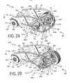
- Figure 2A is a rear perspective view of the vehicle depicted in Figure 1A, wherein the frame of the vehicle is particularly highlighted and the telescoping cylinder actuation system is engaged with the adjustable swing arm axle assembly such that the two rear drive wheels of the vehicle are in a fully retracted (forward) fore-aft position.
- Figure 2B is a rear perspective view of the vehicle depicted in Figure 2A, wherein the frame of the vehicle is particularly highlighted and the telescoping cylinder actuation system is alternatively engaged with the adjustable swing arm axle assembly such that the two rear drive wheels of the vehicle are in a fully extended (rearward) fore-aft position.
- Figure 3 is a top view of the vehicle depicted in Figure 2A, wherein the frame of the vehicle is particularly highlighted and the telescoping cylinder actuation system is engaged with the adjustable swing arm axle assembly such that the two rear drive wheels of the vehicle are in a fully retracted (forward) fore-aft position.
- Figure 4 is a block diagram illustrating how electrical information signals are communicated to an electronic controller onboard the vehicle and how electrical control signals are communicated from the electronic controller to the actuation system.
- Figure 5 is a rear view of the vehicle depicted in Figures 2A and 3, wherein the frame of the vehicle is particularly highlighted and the telescoping cylinder actuation system is engaged with the adjustable swing arm axle assembly such that the two rear drive wheels of the vehicle are in a fully retracted (forward) fore-aft position.
- Figure 6A is a partial cut-away side view of the vehicle depicted in Figures 2A, 3, and 5, wherein the frame of the vehicle is particularly highlighted and the telescoping cylinder actuation system is engaged with the adjustable swing arm axle assembly such that the two rear drive wheels of the vehicle are in a fully retracted (forward) fore-aft position.
- Figure 6B is a partial cut-away side view of the vehicle depicted in Figure 6A, wherein the frame of the vehicle is particularly highlighted and the telescoping cylinder actuation system is alternatively engaged with the adjustable swing arm axle assembly such that the two rear drive wheels of the vehicle are in a fully extended (rearward) fore-aft position.
- Figure 7A is a cut-away side view of a telescoping cylinder actuation system engaged with an adjustable swing arm axle assembly included in an alternative embodiment of the vehicle according to the present invention, wherein the two rear drive wheels of the vehicle are in a fully retracted (forward) fore-aft position.
- Figure 7B is a cut-away side view of the telescoping cylinder actuation system engaged with the adjustable swing arm axle assembly depicted in Figure 7A, wherein the two rear drive wheels of the vehicle are alternatively in a fully extended (rearward) fore-aft position.
- Figure 8A is a cut-away side view of a telescoping cylinder actuation system engaged with an adjustable slide arm axle assembly included in another alternative embodiment of the vehicle according to the present invention, wherein the two rear drive wheels of the vehicle are in a fully retracted (forward) fore-aft position.
- Figure 8B is a cut-away side view of the telescoping cylinder actuation system engaged with the adjustable slide arm axle assembly depicted in Figure 8A, wherein the two rear drive wheels of the vehicle are alternatively in a fully extended (rearward) fore-aft position.
- Figure 9A is a cut-away side view of a rack-and-pinion actuation system engaged with an adjustable swing arm axle assembly included in still another alternative embodiment of the vehicle according to the present invention, wherein the two rear drive wheels of the vehicle are in a fully retracted (forward) fore-aft position.
- Figure 9B is a cut-away side view of the rack-and-pinion actuation system engaged with the adjustable swing arm axle assembly depicted in Figure 9A, wherein the two rear drive wheels of the vehicle are alternatively in a fully extended (rearward) fore-aft position.
- Figure 10 is a rear sectional view of the rack-and-pinion actuation system along with a cross arm assembly of the adjustable swing arm axle assembly depicted in Figures 9A and 9B.
- Figure 11 is a side view of a second embodiment of the vehicle according to the present invention, wherein the vehicle is specifically implemented with two pairs of ground-interacting wheels suitable for traveling over uneven terrain.
- Figure 12 is a side view of a third embodiment of the vehicle according to the present invention, wherein the vehicle is specifically implemented with a single a pair of ground-interacting track assemblies suitable for traveling over uneven terrain.
- the present invention generally provides a vehicle 20 with an actively adjustable axle system 131 situated onboard.
- the vehicle 20 is suitable for traveling over even or uneven terrain with a load.
- the actively adjustable axle system 131 itself generally includes an adjustable axle assembly 86, an actuation system 90, and an electronic controller 96.
- the electronic controller 96 is capable of communicating electrical control signals to the actuation system 90.
- the actuation system 90 is capable of mechanically adjusting the adjustable axle assembly 86 to thereby adjust the fore-aft position of any pair of wheels rotatably mounted on the ends of the adjustable axle assembly 86.
- the electronic controller 96 is capable of communicating electrical control signals to the actuation system 90 to thereby adjust the fore-aft position of the pair of wheels as necessary to actively maintain the overall balance, and particularly the fore-aft stability, of the vehicle 20 as the vehicle 20 travels over various types of terrain, especially uneven terrain.
- a vehicle 20 according to the present invention may be adapted or suited for use as, for example, an automotive vehicle, a recreational vehicle, an agricultural vehicle, a utility vehicle, a construction vehicle, a military vehicle, or a robotic vehicle.
- Detailed descriptions of preferred embodiments of the vehicle 20 according to the present invention are set forth hereinbelow wherein both the structures and operations of the preferred embodiments are discussed.
- FIGS 1A through 6B illustrate a first embodiment 20A of the vehicle 20 according to the present invention.
- the vehicle 20A is a zero turn (ZT) vehicle that includes, as particularly illustrated in Figure 3, a frame 22 having an associated front end 80, a rear end 82, and a fore-aft axis 84 extending therebetween.
- the frame 22 itself includes a plurality of support members 24, 26L, 26R, 28, 30L, 30R, 32L, 32R, 34L, 34R, 36, and 38 and also a plurality of support panels 40L, 40R, and 42 assembled together as particularly illustrated in Figures 2A, 2B, 3, 5, 6A, and 6B. It is to be understood, however, that such support members and support panels may alternatively be formed as an integral whole.
- the vehicle 20A also includes a body 60 that is mounted to the frame 22.
- the body 60 itself optionally includes a roof panel 58, left and right front roof panel support members 57L and 57R, left and right rear roof panel support members 59L and 59R, a front hood panel 62, left and right side panels 64L and 64R, a rear panel 76, left and right front fenders 44L and 44R, and left and right rear fenders 66L and 66R assembled together as particularly illustrated in Figures 1A and 1B.
- a front window 70, left and right side windows 74L and 74R, a rear window 72, left and right head lights (not shown), and left and right tail lights 68L and 68R are successfully accommodated and incorporated within the vehicle 20A as well.
- the body 60 and the frame 22 may alternatively be constructed such that they are substantially integral with each other within a substantially “unitized” or "unibody” construction.
- the vehicle 20A also includes a first embodiment 131A of the actively adjustable axle system 131 with a pair of rear drive wheels 56L and 56R.
- the actively adjustable axle system 131A itself includes a first embodiment 86A of the adjustable axle assembly 86, a first embodiment 90A of the actuation system 90, and the electronic controller 96.
- the adjustable axle assembly 86A as particularly illustrated in Figure 3, is mounted to the rear portion of the frame 22 such that an adjustable axle assembly axis 88 associated with the adjustable axle assembly 86A is aligned substantially orthogonal to the fore-aft axis 84 associated with the frame 22.
- the adjustable axle assembly 86A itself includes a first embodiment 116A of a cross arm assembly 116 and also a pair of swing arms 110L and 110R.
- the cross arm assembly 116A first of all, includes a single cross arm 138.
- the swing arms 110L and 110R in turn, have pivotal ends 112L and 112R pivotally mounted at pivot points 132L and 132R to the frame 22 of the vehicle 20A.
- the swing arms 110L and 110R also have distal ends 114L and 114R interconnected with the cross arm 138 at attachment points 134L and 134R.
- the two rear drive wheels 56L and 56R are rotatably suspended from the two swing arms 110L and 110R proximate the distal ends 114L and 114R thereof.
- suspension of the pair of rear drive wheels 56L and 56R from the pair of swing arms 110L and 110R is particularly achieved with both a pair of suspension arms 130L and 130R and also a pair of strut assemblies 168L and 168R.
- the suspension arms 130L and 130R themselves have, first of all, first ends pivotally fastened at pivot points 128L and 128R to the swing arms 110L and 110R proximate the distal ends 114L and 114R thereof.
- the suspension arms 130L and 130R also have second ends indirectly connected to the swings arms 110L and 110R proximate the pivotal ends 112L and 112R thereof via the strut assemblies 168L and 168R.
- the two strut assemblies 168L and 168R themselves, in turn, include both coil springs 164L and 164R and also shock absorbers (or dampers) 166L and 166R.
- the two rear drive wheels 56L and 56R themselves are particularly rotatably mounted to the middle sections of the two suspension arms 130L and 130R by means of a pair of hub-and-bearing assemblies 170L and 170R as particularly illustrated in Figures 1A through 3 and 5 through 6B.
- the two rear drive wheels 56L and 56R are thereby ultimately rotatably mounted on the ends of the adjustable axle assembly 86A such that the two rear drive wheels 56L and 56R are aligned substantially in parallel and are in mechanical, hydraulic, and/or electrical communication with a power source (not shown) mounted to the frame 22.
- the power source itself may include, for example, at least one engine or motor.
- the two rear drive wheels 56L and 56R of the vehicle 20A are thereby capable of facilitating both moving and independent driving interaction with the ground 103.
- the actuation system 90A includes a pair of telescoping cylinders 126L and 126R serving as left and right actuators.
- the two telescoping cylinders 126L and 126R are preferably connected between the frame 22 of the vehicle 20A and projections 111L and 111R integral with the pivotal ends 112L and 112R of the two swing arms 110L and 110R.
- the two telescoping cylinders 126L and 126R are also electrically connected to the electronic controller 96 which itself is mounted to and/or within the body 60.
- the electronic controller 96 is particularly capable of communicating electrical control signals to the two telescoping cylinders 126L and 126R to thereby adjust the fore-aft position of the pair of rear drive wheels 56L and 56R as necessary to actively maintain the fore-aft stability of the vehicle 20A.
- the vehicle 20A further includes a pair of dolly wheel assemblies 46L and 46R.
- the dolly wheel assemblies 46L and 46R are mounted to the front portion of the frame 22 such that they cooperate with the two rear drive wheels 56L and 56R in generally maintaining the overall balance of the vehicle 20A as the vehicle 20A travels over the ground 103.
- the pair of dolly wheel assemblies 46L and 46R itself includes a pair of ground-interacting dolly wheels 48L and 48R, a matching pair of spindles 54L and 54R, a matching pair of swivel arms 52L and 52R, and a matching pair of swivel joints 50L and 50R.
- the two dolly wheels 48L and 48R are rotatably mounted on the two spindles 54L and 54R.
- the two spindles 54L and 54R are connected to the two swivel arms 52L and 52R.
- the two swivel arms 52L and 52R are swivel mounted to the frame 22 by the two swivel joints 50L and 50R situated underneath the two front fenders 44L and 44R.
- the two dolly wheel assemblies 46L and 46R thereby serve as two supplemental ground-interacting apparatuses which cooperate with the two rear drive wheels 56L and 56R to thereby maintain clearance between both the frame 22 and the body 60 and the ground 103.
- the two ground-interacting dolly wheels 48L and 48R are, by design in this particular embodiment, not capable of being directly steered by a vehicle operator onboard the vehicle 20A. It is to be understood, however, that the two dolly wheels 48L and 48R may optionally be equipped to power rotate in sync or in coordination with the moving speed of the two rear drive wheels 56L and 56R.
- the vehicle 20A also includes an operator control panel 98 situated onboard.
- the operator control panel 98 is capable of receiving operator preference input from a vehicle operator, for example, a human driver, regarding the fore-aft position of the pair of rear drive wheels 56L and 56R.
- Such an operator control panel 98 is preferably mounted within and/or to the body 60 of the vehicle 20A within a vehicle operator cabin 172 or proximate to a designated vehicle operator position.
- the operator control panel 98 is also electrically connected to the electronic controller 96.
- the operator control panel 98 is capable of communicating electrical operator preference input information signals to the electronic controller 96 to thereby adjust the fore-aft position of the pair of rear drive wheels 56L and 56R as necessary, or as desired by the vehicle operator, to actively maintain the fore-aft stability of the vehicle 20A.
- the vehicle 20A additionally includes a pair of attitude sensors 102L and 102R.
- Each attitude sensor 102L and 102R preferably includes conventional gyroscope technology and is therefore capable of sensing the everchanging attitude of the vehicle 20A as it travels across the ground 103 and over uneven terrain 104.
- Each attitude sensor 102L and 102R is preferably mounted to the frame 22 of the vehicle 20A and is electrically connected to the electronic controller 96. In such a configuration, the two attitude sensors 102L and 102R are capable of communicating electrical vehicle attitude information signals to the electronic controller 96 to thereby adjust the fore-aft position of the pair of rear drive wheels 56L and 56R as necessary to actively maintain the fore-aft stability of the vehicle 20A.
- the electronic controller 96 includes, first of all, means for processing the electrical vehicle attitude information signals communicated from each attitude sensor 102L and 102R to thereby actively help determine the center of gravity 100 of the vehicle 20A with its cumulative onboard load as the vehicle 20A travels over uneven terrain 104.
- the electronic controller 96 also includes means for generating the electrical control signals according to the actively determined center of gravity 100 to thereby prompt the actuation system 90A to adjust the fore-aft position of the pair of rear drive wheels 56L and 56R as necessary to actively maintain the fore-aft stability of the vehicle 20A.
- the electrical vehicle attitude information signals processing means and the electrical control signals generating means may be included on one or more electronic microprocessors associated with the electronic controller 96.
- the two attitude sensors 102L and 102R are preferably mounted to the frame 22 of the vehicle 20A on opposite sides of the vehicle 20A.
- the two attitude sensors 102L and 102R are capable of directly sensing the attitude of the vehicle 20A as the vehicle 20A travels over uneven terrain 104 and particularly uphill.
- having a single attitude sensor mounted to the frame 22 would generally suffice, having the two attitude sensors 102L and 102R situated on opposite sides of the vehicle 20A facilitates both cross-checking by the electronic controller 96 of the vehicle attitude information provided by the two attitude sensors 102L and 102R and also the taking into account of any flexing, twisting, or torsion of the frame 22 as the vehicle 20A travels over uneven terrain 104.
- attitude sensor configuration it is to be understood that many different attitude sensor positioning schemes on the frame or within the body of a vehicle pursuant to the present invention may alternatively be adopted.
- the vehicle 20A further includes a plurality of load sensors 106L, 106R, and 106B.
- Each load sensor 106L, 106R, and 106B is capable of conventionally sensing a particular aspect of the cumulative load onboard the vehicle 20A such as, for example, the position and/or weight of the smaller, onboard individual loads that comprise the cumulative load.
- Such individual loads onboard the vehicle 20A may include, for example, a human load (i.e., the vehicle operator) in addition to any object load, for example, luggage, tools, equipment, and/or weapons.
- the load sensors in Figure 4 particularly include, first of all, a left load sensor 106L and a right load sensor 106R situated at opposite corners of the front end 80 of the vehicle 20A.
- a total load sensor 106B is particularly included and situated proximate the axis 88 associated with the adjustable axle assembly 86A at the back end 82 of the vehicle 20A.
- Each such load sensor 106L, 106R, and 106B is preferably mounted to the frame 22 of the vehicle 20A and is electrically connected to the electronic controller 96.
- each load sensor 106L, 106R, and 106B is capable of communicating electrical load information signals to the electronic controller 96 to thereby adjust the fore-aft position of the pair of rear drive wheels 56L and 56R as necessary to actively maintain the fore-aft stability of the vehicle 20A.
- the electronic controller 96 includes, first of all, means for processing the electrical load information signals communicated from each load sensor 106L, 106R, and 106B to thereby actively help determine the center of gravity 100 of the vehicle 20A with its cumulative onboard load as the vehicle 20A travels over uneven terrain 104.
- the electronic controller 96 also includes means for generating the electrical control signals according to the actively determined center of gravity 100 to thereby prompt the actuation system 90A to adjust the fore-aft position of the pair of rear drive wheels 56L and 56R as necessary to actively maintain the fore-aft stability of the vehicle 20A.
- the electrical load information signals processing means and the electrical control signals generating means may be included on one or more electronic microprocessors associated with the electronic controller 96.
- the vehicle 20A still further includes a pair of position sensors 108L and 108R.
- Each position sensor 108L and 108R is capable of conventionally sensing the position of the adjustable axle assembly 86A onboard the vehicle 20A.
- Each position sensor 108L and 108R is preferably mounted to the frame 22 of the vehicle 20A such that each position sensor 108L and 108R is situated proximate to the axis 88 associated with the adjustable axle assembly 86A.
- each position sensor 108L and 108R is also electrically connected to the electronic controller 96.
- each position sensor 108L and 108R is capable of communicating electrical axle assembly position information signals to the electronic controller 96 to thereby adjust the fore-aft position of the pair of rear drive wheels 56L and 56R as necessary to actively maintain the fore-aft stability of the vehicle 20A.
- the electronic controller 96 includes, first of all, means for processing the electrical axle assembly position information signals communicated from each position sensor 108L and 108R to thereby actively help determine the center of gravity 100 of the vehicle 20A with its cumulative onboard load as the vehicle 20A travels over uneven terrain 104.
- the electronic controller 96 also includes means for generating the electrical control signals according to the actively determined center of gravity 100 to thereby prompt the actuation system 90A to adjust the fore-aft position of the pair of rear drive wheels 56L and 56R as necessary to actively maintain the fore-aft stability of the vehicle 20A.
- the electrical axle assembly position information signals processing means and the electrical control signals generating means may be included on one or more electronic microprocessors associated with the electronic controller 96.
- the electronic controller 96 receives electrical vehicle attitude information signals from the attitude sensors 102L and 102R, electrical load information signals from the load sensors 106L, 106R, and 106B, and electrical axle assembly position information signals from the position sensors 108L and 108R on a substantially continuous basis. As all of these electrical information signals are received, the electronic controller 96 promptly processes the electrical information signals. In doing so, the electronic controller 96 thereby attempts to actively determine and monitor the position of the center of gravity 100 of the vehicle 20A together with its cumulative onboard load in relation to the ground contact points of both the two dolly wheels 48L and 48R and also the two rear drive wheels 56L and 56R.
- the vehicle 20A in this particular embodiment is a ZT vehicle
- the vehicle 20A and its component parts are specifically dimensioned, weighted, and assembled such that the overall center of gravity 100 of the vehicle 20A together with its load is naturally predisposed to being well behind the ground contact points of the dolly wheels 48L and 48R and just in front of and over the ground contact points of the two rear drive wheels 56L and 56R when the two rear drive wheels 56L and 56R are in a position forward of the midpoint of the adjustable axle assembly movement range and the vehicle 20A is traveling over ground 103 that is substantially level.
- the electronic controller 96 when the vehicle 20A is traveling over substantially level ground and the electronic controller 96 actively determines that the center of gravity 100 of the vehicle 20A together with its cumulative onboard load is safely situated behind the ground contact points of the two dolly wheels 48L and 48R and also in front of the ground contact points of the two rear drive wheels 56L and 56R, the electronic controller 96 will accordingly generate situation-specific electrical control signals and communicate the electrical control signals to the actuation system 90A.
- the actuation system 90A will then mechanically adjust (i.e., pivot) the adjustable axle assembly 86A only if and as needed to thereby position the two rear drive wheels 56L and 56R in an optimal retracted (forward) fore-aft position as generally illustrated in Figure 6A.
- the vehicle 20A is thereby provided with less inhibited to total uninhibited zero turn capability and therefore increased maneuverability.
- the electronic controller 96 actively determines that the center of gravity 100 has suddenly shifted directly over or behind the ground contact points of the two rear drive wheels 56L and 56R while the vehicle 20A is traveling up a hill, the electronic controller 96 will accordingly generate situation-specific electrical control signals and communicate the electrical control signals to the actuation system 90A.
- the actuation system 90A will then mechanically adjust the adjustable axle assembly 86A only as far as necessary toward a fully extended fore-aft position as in Figure 6B to thereby shift the ground contact points of the two rear drive wheels 56L and 56R back behind the center of gravity 100. In this way, the front end of the vehicle 20A is kept on the ground 103 and the overall balance of the vehicle 20A is thereby safely maintained as the vehicle 20A continues to travel up the hill.
- the vehicle operator may opt to utilize the operator control panel 98 to manually enter operator preference input regarding his choice for moving the pair of rear drive wheels 56L and 56R into a particular fore-aft position.
- electrical operator preference input information signals are communicated to the electronic controller 96.
- the electronic controller 96 In response to receiving such electrical operator preference input information signals, the electronic controller 96 then ignores all other electrical information signals and promptly communicates electrical control signals to the actuation system 90A in accordance with the particular preference of the vehicle operator.
- the fore-aft position of the pair of rear drive wheels 56L and 56R is ultimately adjusted to maintain the fore-aft stability of the vehicle 20A according to the vehicle operator's best judgment.
- a vehicle operator can utilize the operator control panel 98 to manually override the actively adjustable axle system 131 A of the vehicle 20A as desired and as necessary.
- the first embodiment 20A of the vehicle 20 according to the present invention realizes many advantages over other off-road or all-terrain vehicles, and particularly ZT vehicles, commonly in use today.
- the vehicle 20A according to the present invention (1) successfully maintains its balance when traveling directly up a hill, (2) successfully maintains its balance when traveling across a hillside, (3) successfully maintains its balance even when a vehicle operator attempts rapid acceleration, (4) successfully maintains its balance when traveling over terrain with extreme and everchanging topographies, (5) successfully maintains its balance and optimizes traction even when there are significant and frequent changes in human load and/or object load onboard, (6) successfully maintains its balance even under reduced traction conditions, (7) is not unnecessarily limited in maximum zero turn capability when suited for use as a zero turn (ZT) vehicle, and (8) may successfully be adapted or suited for use as either a ZT vehicle or a non-ZT vehicle.
- ZT zero turn
- FIG. 7A and 7B An alternative embodiment 131B of the actively adjustable axle system 131 is illustrated in Figures 7A and 7B.
- the alternative embodiment 131B of the actively adjustable axle system 131 as does the first embodiment 131A, generally includes the first embodiment 86A of the adjustable axle assembly 86, the first embodiment 90A of the actuation system 90, and the electronic controller 96.
- the two telescoping cylinders 126L and 126R of the actuation system 90A in this alternative embodiment 131 B are instead connected between the frame 22 of the vehicle 20A and the two swing arms 110L and 110R proximate their distal ends 114L and 114R.
- the actively adjustable axle system 131C includes a second embodiment 86B of the adjustable axle assembly 86, the first embodiment 90A of the actuation system 90, and the electronic controller 96.
- the adjustable axle assembly 86B itself includes a pair of slide arms 118L and 118R as well as a second embodiment 116B of the cross arm assembly 116.
- the two slide arms 118L and 118R first of all, are slidingly engaged within two slots 25L and 25R defined within the frame 22 of the vehicle 20A.
- the cross arm assembly 116B includes both a first cross arm (not shown) that interconnects the two slide arms 118L and 118R at attachment points 136L and 136R and also a second cross arm (not shown) that similarly interconnects the two slide arms 118L and 118R at attachment points 137L and 137R.
- the rear drive wheels 56L and 56R in this alternative embodiment 131C are instead rotatably suspended from the slide arms 118L and 118R.
- the two telescoping cylinders 126L and 126R of the actuation system 90A in cooperation therewith, are connected between the frame 22 of the vehicle 20A and the two slide arms 118L and 118R.
- the actively adjustable axle system 131 D includes the first embodiment 86A of the adjustable axle assembly 86, a second embodiment 90B of the actuation system 90, and the electronic controller 96.
- the actuation system 90B itself includes a pair of racks 120L and 120R, a pair of pinion gears 122L and 122R, and an electric motor 124.
- the two racks 120L and 120R, first of all, are fixed to the frame 22 of the vehicle 20A.
- the two pinion gears 122L and 122R are generally rotatably mounted to the distal ends 114L and 114R of the two swing arms 110L and 110R such that the two pinion gears 122L and 122R are engaged with the two racks 120L and 120R.
- the electric motor 124 is preferably a stepping-type motor that is electrically connected to the electronic controller 96 and thereby microprocessor-controlled.
- the cross arm assembly 116 of the adjustable axle assembly 86A has a third embodiment 116C, as particularly illustrated in Figure 10, adapted to include a hollow cross arm 142.
- the hollow cross arm 142 first of all, interconnects the two swing arms 110L and 110R in a fixed fashion at attachment points 144L and 144R.
- the hollow cross arm 142 in addition, includes a rotatable pinion shaft 150 within its hollow having opposite ends that are rotatably received and mounted within bearings 146L and 146R situated within the distal ends 114L and 114R of the two swing arms 110L and 110R.
- the two pinion gears 122L and 122R are both particularly fixed onto the rotatable pinion shaft 150 proximate the opposite ends thereof such that the two pinion gears 122L and 122R rotate in unison with the rotatable pinion shaft 150.
- the electric motor 124 in addition to being electrically connected to the electronic controller 96, is also mounted onto the exterior of the hollow cross arm 142 in a fixed fashion such that a rotatable output drive shaft 152 protruding from the electric motor 124 is substantially parallel with the rotatable pinion shaft 150.
- a primary drive gear 156 is fixed thereon such that the rotatable output drive shaft 152 and the primary drive gear 156 rotate in unison.
- a mating drive gear 154 fixed onto or integral with the middle portion of the rotatable pinion shaft 150 is meshingly engaged with the primary drive gear 156.
- the electronic controller 96 during operation is capable of communicating electrical control signals to the electric motor 124.
- the electric motor 124 then "steps" or rotates the output drive shaft 152 along with the primary drive gear 156 in accordance with the electrical control signals received from the electronic controller 96.
- the mating drive gear 154 engaged with the primary drive gear 156 accordingly causes concomitant rotation in both the pinion shaft 150 and the two pinion gears 122L and 122R fixed thereon. In this way, stepped or incremental movement of the two pinion gears 122L and 122R in either direction along the two racks 120L and 120R is ultimately realized.
- the adjustable axle assembly 86A is correspondingly moved (i.e., pivoted), thereby adjusting the fore-aft position of the two rear drive wheels 56L and 56R as necessary to actively maintain the fore-aft stability of the vehicle 20A during operation.
- the vehicle 20B includes a seat 160 for accommodating a vehicle operator within the vehicle operator cabin 172.
- the vehicle 20B also includes an operator steering control 158 incorporated within the operator control panel 98 (see Figure 4) situated in the vehicle operator cabin 172.
- the vehicle 20B also includes a wheelie bar 78 mounted to the rear end 82 of the vehicle 20B for helping prevent the vehicle 20B from being altogether upended should the front end 80 of the vehicle 20B ever come off the ground when traveling up a steep hill.
- the actively adjustable axle system 131 will generally maintain the adjustable axle assembly 86 along with the two rear drive wheels 56L and 56R in a fully retracted (forward) fore-aft position. Such is appropriate, first of all, since the center of gravity 100 of the vehicle 20B with its cumulative onboard load as actively determined by the electronic controller 96 is safely situated behind the ground contact points of the two dolly wheels 48L and 48R and also just in front of the ground contact points of the two rear drive wheels 56L and 56R.
- the center of gravity 100 of the vehicle 20B with its cumulative onboard load is safely situated over both the two dolly wheels 48L and 48R and the two rear drive wheels 56L and 56R such that the vehicle 20B will not tip over and become altogether upended and also such that maximum traction is realized by the two rear drive wheels 56L and 56R.
- Such is appropriate also because maintaining the rear drive wheels 56L and 56R in a fully retracted (forward) fore-aft position whenever feasible provides the vehicle 20B with enhanced, axle-centric balance for maximizing zero turn capability and therefore increased maneuverability.
- the actively adjustable axle system 131 will then adjust the adjustable axle assembly 86 along with the two rear drive wheels 56L and 56R toward an extended (rearward) fore-aft position as necessary to thereby safely maintain the overall balance of the vehicle 20B. Any such necessary adjustment is timely initiated by the electronic controller 96 in response to its own active determination of the center of gravity 100 of the vehicle 20B with its cumulative onboard load.
- the vehicle 20C uniquely includes, first of all, an anti-tip disc 92 serving as a supplemental ground-interacting apparatus for the purpose of safety.
- the vehicle 20C also uniquely includes a pair of ground-interacting track assemblies 94L and 94R.
- Such ground-interacting track assemblies 94L and 94R are preferably mounted to both the adjustable axle assembly 86 and a forward suspension 140 of the vehicle 20C such that the two rear drive wheels 56L and 56R are engaged within the two ground-interacting track assemblies 94L and 94R to thereby facilitate moving interaction with the ground 103.
- the actively adjustable axle system 131 will generally maintain the adjustable axle assembly 86 along with both the two rear drive wheels 56L and 56R and also the two track assemblies 94L and 94R in a fully retracted (forward) fore-aft position.
- the actively adjustable axle system 131 will then adjust the adjustable axle assembly 86 along with both the two rear drive wheels 56L and 56R and also the two track assemblies 94L and 94R toward an extended (rearward) fore-aft position as necessary to thereby safely maintain the overall balance of the vehicle 20C.
- a vehicle pursuant to the present invention may alternatively have dependent front or rear 2-wheel drive capability, 4-wheel drive capability, or even all-wheel drive capability.
- a vehicle pursuant to the present invention may have an independent, non-independent, or semi-independent suspension system.
- suspension system springs a vehicle pursuant to the present invention may, as an alternative to coil springs, instead include leaf springs, air springs, or torsion bar springs.
- a vehicle pursuant to the present invention may, as an alternative to having two dolly wheels and two wheels with independent 2-wheel drive, instead have two largely non-steerable wheels and two wheels directly steerable with a traditional linkage or rack-and-pinion steering system.
- actuation system it is to be understood that many different types of actuators may alternatively be utilized on a vehicle pursuant to the present invention, including, for example, hydraulic, electric, pneumatic, or mechanical linkage type actuators, or even combinations thereof.
- any actuation system incorporating one or more of such actuators may optionally be designed to adjust the fore-aft positions of vehicle wheels either together in pairs or independently and individually pursuant to the present invention.
- the vehicle with actively adjustable axle system for traveling over uneven terrain with a load realizes many advantages over other off-road or all-terrain vehicles commonly in use today.
- the vehicle according to the present invention (1) successfully maintains its balance when traveling directly up a hill, (2) successfully maintains its balance when traveling across a hillside, (3) successfully maintains its balance even when a vehicle operator attempts rapid acceleration, (4) successfully maintains its balance when traveling over terrain with extreme and everchanging topographies, (5) successfully maintains its balance and optimizes traction even when there are significant and frequent changes in human load and/or object load onboard, (6) successfully maintains its balance even under reduced traction conditions, (7) is not unnecessarily limited in maximum zero turn capability when suited for use as a zero turn (ZT) vehicle, and (8) may successfully be adapted or suited for use as either a ZT vehicle or a non-ZT vehicle.
- ZT zero turn
Priority Applications (1)
| Application Number | Priority Date | Filing Date | Title |
|---|---|---|---|
| EP05251802A EP1705037A1 (fr) | 2005-03-23 | 2005-03-23 | Véhicule avec un système d'essieu à contrôle actif |
Applications Claiming Priority (1)
| Application Number | Priority Date | Filing Date | Title |
|---|---|---|---|
| EP05251802A EP1705037A1 (fr) | 2005-03-23 | 2005-03-23 | Véhicule avec un système d'essieu à contrôle actif |
Publications (1)
| Publication Number | Publication Date |
|---|---|
| EP1705037A1 true EP1705037A1 (fr) | 2006-09-27 |
Family
ID=34940627
Family Applications (1)
| Application Number | Title | Priority Date | Filing Date |
|---|---|---|---|
| EP05251802A Withdrawn EP1705037A1 (fr) | 2005-03-23 | 2005-03-23 | Véhicule avec un système d'essieu à contrôle actif |
Country Status (1)
| Country | Link |
|---|---|
| EP (1) | EP1705037A1 (fr) |
Cited By (1)
| Publication number | Priority date | Publication date | Assignee | Title |
|---|---|---|---|---|
| GB2468487A (en) * | 2009-03-09 | 2010-09-15 | Nissan Motor Mfg | Vehicle suspension |
Citations (4)
| Publication number | Priority date | Publication date | Assignee | Title |
|---|---|---|---|---|
| US3369624A (en) * | 1961-03-10 | 1968-02-20 | Armes De Guerre Fab Nat | Parachutable,self-propelled endless track vehicle |
| JPS59149873A (ja) * | 1983-02-15 | 1984-08-27 | Nissan Motor Co Ltd | 折り畳み式自動車 |
| FR2694240A1 (fr) | 1992-07-30 | 1994-02-04 | Matra Automobile | Véhicule automobile à empattement variable. |
| FR2700501A1 (fr) * | 1993-01-19 | 1994-07-22 | Renault | Véhicule de franchissement d'obstacles. |
-
2005
- 2005-03-23 EP EP05251802A patent/EP1705037A1/fr not_active Withdrawn
Patent Citations (4)
| Publication number | Priority date | Publication date | Assignee | Title |
|---|---|---|---|---|
| US3369624A (en) * | 1961-03-10 | 1968-02-20 | Armes De Guerre Fab Nat | Parachutable,self-propelled endless track vehicle |
| JPS59149873A (ja) * | 1983-02-15 | 1984-08-27 | Nissan Motor Co Ltd | 折り畳み式自動車 |
| FR2694240A1 (fr) | 1992-07-30 | 1994-02-04 | Matra Automobile | Véhicule automobile à empattement variable. |
| FR2700501A1 (fr) * | 1993-01-19 | 1994-07-22 | Renault | Véhicule de franchissement d'obstacles. |
Non-Patent Citations (1)
| Title |
|---|
| PATENT ABSTRACTS OF JAPAN vol. 008, no. 280 (M - 347) 21 December 1984 (1984-12-21) * |
Cited By (2)
| Publication number | Priority date | Publication date | Assignee | Title |
|---|---|---|---|---|
| GB2468487A (en) * | 2009-03-09 | 2010-09-15 | Nissan Motor Mfg | Vehicle suspension |
| GB2468487B (en) * | 2009-03-09 | 2013-05-01 | Nissan Motor Mfg Uk Ltd | Vehicle suspension |
Similar Documents
| Publication | Publication Date | Title |
|---|---|---|
| US20060254840A1 (en) | Vehicle for traveling over uneven terrain | |
| US20060254841A1 (en) | Vehicle with adjustable axle system for actively maintaining stability | |
| CN1572644B (zh) | 带有前部两轮转向机构的三轮轮式车辆 | |
| US9701339B2 (en) | Vehicle with tilting frame | |
| US7527117B2 (en) | Vehicle with actively adjustable axle system | |
| US8645024B2 (en) | Motorized three-wheeled vehicle active suspension | |
| US4487429A (en) | Tilting wheel vehicle suspension system | |
| US8517135B2 (en) | Vehicle suspension system having adjustable track width | |
| CN102202921A (zh) | 水陆两用车辆中的或与水陆两用车辆相关的改进 | |
| US20050206101A1 (en) | Four wheel drive stationary body vehicle having controlled wheel and passenger compartment lateral lean with independent steering | |
| EP3256367B1 (fr) | Véhicule motorisé à cabine pivotante combinant des caractéristiques d'automobiles et de motocyclettes | |
| US20070151777A1 (en) | Wheel Arrangement For A Four-Wheeled Vehicle | |
| CN105829201A (zh) | 用于多轮式侧倾车辆的侧倾机构 | |
| CN101102930A (zh) | 履带式全地形车 | |
| AU2014311254A1 (en) | Apparatus for board sports | |
| US20220355884A1 (en) | Vehicle with a stability system that compensates for the centrifugal force and the transverse component of the inertia force when cornering | |
| CN112172921A (zh) | 车辆侧倾驱动机构及应用该机构的主动侧倾车辆 | |
| CN110936784B (zh) | 车身侧倾控制机构及应用该机构的主动侧倾车辆 | |
| US5088570A (en) | Steerable rear dual axle system for large trucks | |
| US7338061B2 (en) | Stabilized vehicle using articulating joint | |
| US8607913B2 (en) | Motorized three-wheeled vehicle rear steering mechanism | |
| EP1705037A1 (fr) | Véhicule avec un système d'essieu à contrôle actif | |
| EP1905675B1 (fr) | Arrangement de roues d'un véhicule à quatre roues | |
| JPS6013870B2 (ja) | 自動車用かじ取り装置 | |
| US4283074A (en) | Narrow track economy motor vehicle |
Legal Events
| Date | Code | Title | Description |
|---|---|---|---|
| PUAI | Public reference made under article 153(3) epc to a published international application that has entered the european phase |
Free format text: ORIGINAL CODE: 0009012 |
|
| AK | Designated contracting states |
Kind code of ref document: A1 Designated state(s): AT BE BG CH CY CZ DE DK EE ES FI FR GB GR HU IE IS IT LI LT LU MC NL PL PT RO SE SI SK TR |
|
| AX | Request for extension of the european patent |
Extension state: AL BA HR LV MK YU |
|
| 17P | Request for examination filed |
Effective date: 20070301 |
|
| AKX | Designation fees paid |
Designated state(s): AT BE BG CH CY CZ DE DK EE ES FI FR GB GR HU IE IS IT LI LT LU MC NL PL PT RO SE SI SK TR |
|
| 17Q | First examination report despatched |
Effective date: 20080722 |
|
| GRAP | Despatch of communication of intention to grant a patent |
Free format text: ORIGINAL CODE: EPIDOSNIGR1 |
|
| GRAL | Information related to payment of fee for publishing/printing deleted |
Free format text: ORIGINAL CODE: EPIDOSDIGR3 |
|
| GRAS | Grant fee paid |
Free format text: ORIGINAL CODE: EPIDOSNIGR3 |
|
| GRAS | Grant fee paid |
Free format text: ORIGINAL CODE: EPIDOSNIGR3 |
|
| STAA | Information on the status of an ep patent application or granted ep patent |
Free format text: STATUS: THE APPLICATION IS DEEMED TO BE WITHDRAWN |
|
| 18D | Application deemed to be withdrawn |
Effective date: 20101001 |