EP1704019B1 - Rotating toolholder - Google Patents
Rotating toolholder Download PDFInfo
- Publication number
- EP1704019B1 EP1704019B1 EP03819146A EP03819146A EP1704019B1 EP 1704019 B1 EP1704019 B1 EP 1704019B1 EP 03819146 A EP03819146 A EP 03819146A EP 03819146 A EP03819146 A EP 03819146A EP 1704019 B1 EP1704019 B1 EP 1704019B1
- Authority
- EP
- European Patent Office
- Prior art keywords
- safety member
- toolholder
- safety
- bush
- spindle
- Prior art date
- Legal status (The legal status is an assumption and is not a legal conclusion. Google has not performed a legal analysis and makes no representation as to the accuracy of the status listed.)
- Expired - Lifetime
Links
- 230000008878 coupling Effects 0.000 description 16
- 238000010168 coupling process Methods 0.000 description 16
- 238000005859 coupling reaction Methods 0.000 description 16
- 238000012423 maintenance Methods 0.000 description 4
- 229910000831 Steel Inorganic materials 0.000 description 3
- 239000010959 steel Substances 0.000 description 3
- 238000010276 construction Methods 0.000 description 1
- 238000006073 displacement reaction Methods 0.000 description 1
- 230000000694 effects Effects 0.000 description 1
- 238000003780 insertion Methods 0.000 description 1
- 230000037431 insertion Effects 0.000 description 1
- 238000003754 machining Methods 0.000 description 1
- 239000000463 material Substances 0.000 description 1
- 238000003801 milling Methods 0.000 description 1
- 238000012986 modification Methods 0.000 description 1
- 230000004048 modification Effects 0.000 description 1
- 238000009877 rendering Methods 0.000 description 1
- 238000003466 welding Methods 0.000 description 1
Images



Classifications
-
- B—PERFORMING OPERATIONS; TRANSPORTING
- B23—MACHINE TOOLS; METAL-WORKING NOT OTHERWISE PROVIDED FOR
- B23Q—DETAILS, COMPONENTS, OR ACCESSORIES FOR MACHINE TOOLS, e.g. ARRANGEMENTS FOR COPYING OR CONTROLLING; MACHINE TOOLS IN GENERAL CHARACTERISED BY THE CONSTRUCTION OF PARTICULAR DETAILS OR COMPONENTS; COMBINATIONS OR ASSOCIATIONS OF METAL-WORKING MACHINES, NOT DIRECTED TO A PARTICULAR RESULT
- B23Q5/00—Driving or feeding mechanisms; Control arrangements therefor
- B23Q5/02—Driving main working members
- B23Q5/04—Driving main working members rotary shafts, e.g. working-spindles
Definitions
- This invention relates to a rotating toolholder according to the preamble of claim 1.
- rotating toolholder may find application when used on a rotating toolholder turret or as an individual toolholder.
- a toolholding turret comprises a base body and a table which is rotatably mounted on the base body.
- the table is provided with housings to receive a plurality of spindles which are successively moved into a working position where an actuator is provided to cause the spindle located there to rotate.
- Rotary motion is provided to the spindle through coupling means provided at the shank of each spindle and corresponding matching means provided on the actuator.
- the coupling means of each spindle are provided with centering members which keep the spindle orientated during the non-working stage, for example during the stage of angular movement of the table.
- these members comprise a sleeve which is able to move on the spindle and rotates with it as one piece and is provided with a pair of radially projecting teeth.
- the teeth engage an annular groove provided internally in the spindle housing so as to allow it to rotate.
- the object of this invention is to provide a rotating toolholder having structural and functional characteristics such as to satisfy the abovementioned requirements and at the same time to overcome the disadvantages mentioned in relation to the known art. This object is accomplished through a rotating toolholder according to claim 1.
- Another object of the invention is to provide a rotating toolholder capable of rendering any maintenance and/or replacement of the centering/safety members easy.
- 1 indicates as a whole a rotating toolholder according to this invention.
- Toolholder 1 comprises a spindle 2 mounted in a housing 3 so that it can rotate about a longitudinal axis X-X, and a bush 4 associated with the spindle 2 so as to be able to move axially along longitudinal axis X-X and rotating as one piece with the spindle 2.
- the bush 4 has at one end 4a thereof a flange 15 able to abut against an axial stop member 16 provided at one head end 17 of the housing 3 in order to limit the axial movement of the bush 4 towards the head end 9 of the shank 2a of the spindle 2.
- the spindle 2 is provided on the side opposite that of the end 2a with a tool 13, for example a drill bit, to carry out an operation on a workpiece.
- a tool 13 for example a drill bit
- the bush 4 is externally associated with the shank 2a of the spindle 2 through an axially grooved coupling 5 and 6 which allows the bush 4 to move axially with respect to the spindle 2 along the axis X-X while maintaining the constraint ensuring rotation about the axis X-X.
- Rotary motion is provided to the spindle 2 through coupling means provided on the shank 2a by corresponding matching means 14 (illustrated in the figure by dashed lines) provided on an actuator (not shown in the figures), which may for example be an electric motor.
- the coupling means for spindle 2 take the form of axial coupling 5 and 6 provided on the shank 2a of the spindle 2, but alternatively it is possible to provide a different arrangement as described for example in Italian patent IT-1236912 .
- matching coupling means 14 of the actuator are designed to act on the bush 4 to cause it to move axially with respect to the spindle 2 along the axis X-X in the direction indicated by B in Figure 4 .
- matching coupling means 14 act on the end 4b of the bush 4 which is opposite to the end 4a where flange 15 is provided.
- elastic means 7 take the form of a helical spring which acts between the shoulder 8 of the shank 2a and the end 4a of bush 4 in such a way as to exert an axial thrust on the bush 4 in the direction of the head end 9 of the shank 2a of the spindle 2.
- the toolholder 1 also comprises safety means 10, 11 which can move reversibly from a disengaged configuration in which they allow spindle 2 to rotate ( Figure 4 ) and an engaged configuration ( Figure 3 ) in which they interact together to oppose rotation of the spindle 2.
- the bush 4 can move axially between an operating position ( Figure 4 ) and a stand-by position ( Figure 3 ).
- the safety means 10 and 11 are disengaged and the spindle 2 is free to rotate about the axis X-X.
- the spindle 2 can be caused to rotate by an actuator, such as for example an electric motor, through the matching coupling means 14. In this way, the tool 13 carried by spindle 2 is caused to rotate and can carry out the machining operation.
- the axial stop member 16 is removably associated with the housing 3 by a notch 19 provided at the end 17 of the housing 3 and is constituted of a screw 18 able to secure a washer 20, in the example of rectangular shape, which acts as an axial stop for the flange 15 of the bush 4.
- a notch 19 provided at the end 17 of the housing 3 and is constituted of a screw 18 able to secure a washer 20, in the example of rectangular shape, which acts as an axial stop for the flange 15 of the bush 4.
- the bush 4 can be mounted on the shank 2a of the spindle 2 even when the toolholder 1 has already been assembled.
- axial stop member 16 may comprise an open elastic ring or a Seeger ring.
- the safety means 10,11 comprise a first safety member associated with the housing 3 and a second safety member associated with the bush 4.
- at least one of the safety members is movable through a movement having a radial component with respect to longitudinal axis X-X between an engaged position ( Figure 3 ) and a disengaged position ( Figure 5 ) in which it respectively engages and disengages the other safety member.
- the safety members are a first movable safety member 10 and a second stationary safety member 11.
- the movable safety member 10 is associated with the housing 3 while the stationary safety member 11 is associated with the bush 4.
- the movable safety member 10 could be associated with the bush 4 while the stationary safety member 11 could be associated with the housing 3.
- safety members 10 and 11 may both be capable of movement with respect to each other.
- the safety member 10 can move in a substantially radial direction Y-Y.
- the toolholder 1 further comprises second elastic means 12 which act at least on one of the safety members 10, 11 with a predetermined elastic load F 2 to keep the safety member engaged with the other safety member. In this way the angular orientation of the spindle 2 is maintained when the bush 4 is in the stand-by position.
- the elastic means 12 act on the movable safety member 10 with a predetermined elastic load F 2 to keep it engaged with the safety member 11.
- the safety member 10 has the form of a tooth extending in a predominantly radial direction Y-Y while the safety member 11 has the form of a slot made in the flange 15 of the bush 4.
- the slot 11 extends along longitudinal axis X-X to allow the tooth 10 to engage and disengage with the slot 11 through axial movement of the bush 4 from the stand-by position ( Figure 3 ) to the operating position ( Figure 4 ).
- the tooth 10 In order to allow the tooth 10, in the stand-by position, to disengage from the slot 11 against elastic load F 2 of elastic means 12, the tooth 10 has at least one surface inclined with respect to the radial direction Y-Y, in the case in point two which are indicated by 10a and 10b and which are provided on the sides of the tooth 10.
- Inclined surfaces 10a and 10b act as guides when the tooth 10 is disengaging from the slot 11 against the elastic load F 2 of the elastic means 12.
- the tooth 10 is partly inserted in the slot 11 and as a result of inclined surfaces 10a and 10b can disengage from the slot 11 against the elastic load of elastic means 12.
- inclined surfaces may be provided on the inner walls of the slot 11.
- elastic means 12 comprise a leaf spring which is in itself known and is made, for example, from harmonic steel.
- the leaf spring 12 is secured at one end 12a to the housing 3, for example through a screw 25, and has the safety member 10 at the other free end 12b.
- the elastic means 12 and the safety member 10 form a single member made in one piece, indicated by 21.
- the member 21 which carries the elastic means 12 and the safety member 10 is more robust and has greater mechanical strength while leaving the elasticity provided by elastic means 12 unchanged.
- the housing 3 has a notch 23 provided in housing 3, for example by milling.
- the notch 23 has two surfaces 23a and 23b which extend longitudinally and radially so as to define a guide seat 30 for the tooth 10 when it is moving radially from and towards the longitudinal slot 11.
- rotating toolholder 100 as a whole indicates a rotating toolholder according to a second alternative embodiment of this invention.
- the parts of rotating toolholder 100 which are structurally and functionally equivalent to rotating toolholder 1 are referred to using the same reference numbers and will not be described further. This also applies to the further embodiments which will be described below.
- the safety member 10 has the form of a sphere which is subjected to the elastic load of the elastic means 12. This embodiment avoids the use of inclined surfaces on the movable safety member 10 while at the same time assisting the safety member 10 to disengage from the slot 11.
- the sphere 10 In order to allow the sphere 10 to disengage from the slot 11, the sphere 10 is partly inserted into th eslot 11 and as a result of its curved surface can disengage from the slot 11 against the elastic load of the elastic means 12. For example, the sphere 10 inserts into the slot 11 until the tangent at the point of contact between the sphere 10 and the inner surfaces of the slot 11 forms an angle, with respect to the radial axis Y-Y, which lies outside the self-locking range, for example an angle greater than 45°.
- the housing 23 hays a through radial hole 130 defining a cylindrical guide seat for the sphere 10 in its radial movement towards and away from the slot 11.
- 200 indicates as a whole a rotating toolholder according to a third alternative embodiment of this invention.
- a single-piece member 221 which comprises the elastic means 12 and the tooth 10 is secured to a sleeve 222, for example by welding.
- This arrangement makes it possible to apply safety means according to the invention also in the case where the diameter of the shank 2a of the spindle 2 is too small to allow a leaf spring 12 to be secured by means of a screw as described with reference to the first and second embodiments described above.
- the sleeve 222 may be made of a material which is different from that of the single-piece member 221 incorporating the leaf spring 12 and the tooth 10.
- the sleeve 222 may be of steel while single-piece member 221 is of harmonic steel for springs.
- an annular seat extending axially along the longitudinal axis X-X is provided within the inner walls of the housing 3 so as to form a cylindrical seat 230 capable of receiving the sleeve 222 and having a stop base 231 against which the end 222a of the sleeve 222 abuts.
- a stop ring 216 for example of the Seeger type, associated with the end 222b of the sleeve 222, which is opposite to the end 222a, is used to prevent axial movement of the sleeve 222 along the axis X-X in the seat 230. It will be noted that, advantageously, the ring 216 acts also as an axial stop member for the flange 15 of the bush 4. The use of screw 18 and washer 20 as a removable axial stop member is avoided in this way.
- the single-piece member 221, in proximity of the tooth 10, is of an undulating shape such as to form a projection 224 which facilitates insertion of the sleeve 222 into the housing 3 and its correct angular position.
- 300 indicates as a whole a rotating toolholder according to a fourth alternative embodiment of this invention.
- a single-piece member 321 carrying the elastic means 12 and the safety tooth 10 can be made of one piece in a sleeve 322 as shown in Figures 18-20 .
- this embodiment makes it possible to obtain the elastic means 12, the safety member 10 and the sleeve 322 in a single piece.
- the rotating toolholder according to this invention makes it possible to satisfy the requirements and overcome the disadvantages mentioned in the introductory part of this description in comparison with the known art.
- the advantages deriving from the use of this invention mainly lie in the fact that it provides a toolholder whose centering bush can be fitted and replaced even when the toolholder is assembled, avoiding dismantling of the toolholder.
Landscapes
- Engineering & Computer Science (AREA)
- Mechanical Engineering (AREA)
- Jigs For Machine Tools (AREA)
Description
- This invention relates to a rotating toolholder according to the preamble of claim 1.
- In particular the rotating toolholder according to this invention may find application when used on a rotating toolholder turret or as an individual toolholder.
- An example of a rotating toolholder according to the preamble of claim 1 is described in Italian patent
IT-1236912 - Rotary motion is provided to the spindle through coupling means provided at the shank of each spindle and corresponding matching means provided on the actuator. The coupling means of each spindle are provided with centering members which keep the spindle orientated during the non-working stage, for example during the stage of angular movement of the table. In particular these members comprise a sleeve which is able to move on the spindle and rotates with it as one piece and is provided with a pair of radially projecting teeth. When the actuator is engaged with the coupling means of the spindle the teeth engage an annular groove provided internally in the spindle housing so as to allow it to rotate. Conversely, when the actuator is disengaged from the coupling means the teeth engage an axial groove thus preventing rotation of the spindle and loss of its angular orientation. However, toolholders of the type mentioned above, although making it possible to correctly maintain the angular position of the spindle with respect to the actuator, have considerable disadvantages when the actuator does not engage the coupling means correctly, a situation which can for example arise when the actuator is correctly engaged with the coupling means of the spindle but is not fully inserted to bring about axial displacement of the sleeve to effect complete disengagement of the teeth from the axial groove and their engagement in the annular groove. In this situation the centering members can suffer damage or breakage after the application of a torque by the actuator and replacement of the sleeve is therefore necessary. When it is necessary to replace the sleeve carrying the engaging teeth or other internal members of the device it is necessary to remove the toolholder from the rotating toolholder table and dismantle the toolholder from the front in order to remove the sleeve. In the extreme it may even be necessary to send the toolholder to the manufacturer for the necessary repair or replacements. This obviously gives rise to a number of disadvantages from both the economical point of view and from the point of view of maintenance times.
- As a consequence, there is a strongly need to have rotating toolholders provided with safety means to protect the centering devices from any damage and/or breakage.
- The object of this invention is to provide a rotating toolholder having structural and functional characteristics such as to satisfy the abovementioned requirements and at the same time to overcome the disadvantages mentioned in relation to the known art. This object is accomplished through a rotating toolholder according to claim 1.
- Another object of the invention is to provide a rotating toolholder capable of rendering any maintenance and/or replacement of the centering/safety members easy.
- Further features and advantages of the rotating toolholder according to this invention will be apparent from the following description of a preferred embodiment provided non-restrictively by way of indication with reference to the appended figures, in which:
-
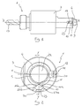
Figure 1 shows a schematic view of a rotating toolholder according to the invention, -
Figure 2 shows a frontal view in partial cross-section of the rotating toolholder inFigure 1 , -
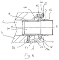
Figures 3 to 5 show views of the toolholder inFigure 1 in cross-section along the line Y-Y inFigure 2 , in different operating configurations, -
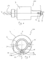
Figure 6 shows a schematic view of a rotating toolholder according to a second embodiment of the invention, -
Figure 7 shows a front view in partial cross-section of the rotating toolholder inFigure 6 , -
Figures 8 to 10 show views of the toolholder inFigure 6 in cross-section along the line Y-Y inFigure 7 , in different operating configurations, -
Figure 11 shows a front view in partial cross-section of a toolholder according to a third embodiment of the invention, -
Figure 12 shows a schematic perspective view of a detail of the toolholder inFigure 11 , -
Figure 13 shows a view of the detail inFigure 12 in cross-section along the line Y-Y inFigure 11 , -
Figure 14 shows a view of the detail inFigure 12 in cross-section along the line X-X inFigure 13 , -
Figures 15 to 17 show views of the toolholder inFigure 11 in cross-section along the line Y-Y in different operating configurations, -
Figure 18 shows a schematic perspective view of a detail of a toolholder according to a fourth embodiment, -
Figure 19 shows a view of the detail inFigure 18 in cross-section along the line Y-Y inFigure 11 , -
Figure 20 shows a view of the detail inFigure 18 in cross-section along the line X-X inFigure 19 , -
Figures 21 to 23 show views in partial cross-section of a toolholder according to the fourth embodiment, in different operating configurations. - With reference to the appended
figures, 1 indicates as a whole a rotating toolholder according to this invention. - Toolholder 1 comprises a
spindle 2 mounted in ahousing 3 so that it can rotate about a longitudinal axis X-X, and a bush 4 associated with thespindle 2 so as to be able to move axially along longitudinal axis X-X and rotating as one piece with thespindle 2. According to a preferred embodiment the bush 4 has at one end 4a thereof aflange 15 able to abut against anaxial stop member 16 provided at onehead end 17 of thehousing 3 in order to limit the axial movement of the bush 4 towards thehead end 9 of the shank 2a of thespindle 2. - In a way which is in itself known, the
spindle 2 is provided on the side opposite that of the end 2a with atool 13, for example a drill bit, to carry out an operation on a workpiece. - According to a preferred embodiment the bush 4 is externally associated with the shank 2a of the
spindle 2 through an axiallygrooved coupling spindle 2 along the axis X-X while maintaining the constraint ensuring rotation about the axis X-X. - Rotary motion is provided to the
spindle 2 through coupling means provided on the shank 2a by corresponding matching means 14 (illustrated in the figure by dashed lines) provided on an actuator (not shown in the figures), which may for example be an electric motor. In the example the coupling means forspindle 2 take the form ofaxial coupling spindle 2, but alternatively it is possible to provide a different arrangement as described for example in Italian patentIT-1236912 - In a manner which is in itself conventional, matching coupling means 14 of the actuator are designed to act on the bush 4 to cause it to move axially with respect to the
spindle 2 along the axis X-X in the direction indicated by B inFigure 4 . For example matching coupling means 14 act on theend 4b of the bush 4 which is opposite to the end 4a whereflange 15 is provided. - Axial movement of the bush 4 in the longitudinal direction X-X, in particular in the direction B, is opposed by
elastic means 7 which act on the bush 4 with a predetermined elastic load F1, In the example illustrated in the figures elastic means 7 take the form of a helical spring which acts between theshoulder 8 of the shank 2a and the end 4a of bush 4 in such a way as to exert an axial thrust on the bush 4 in the direction of thehead end 9 of the shank 2a of thespindle 2. - The toolholder 1 also comprises safety means 10, 11 which can move reversibly from a disengaged configuration in which they allow
spindle 2 to rotate (Figure 4 ) and an engaged configuration (Figure 3 ) in which they interact together to oppose rotation of thespindle 2. - In order to allow mutual engagement and disengagement of safety means 10 and 11, the bush 4 can move axially between an operating position (
Figure 4 ) and a stand-by position (Figure 3 ). - When the bush 4 is in the operating position, the safety means 10 and 11 are disengaged and the
spindle 2 is free to rotate about the axis X-X. In particular when the bush 4 is in the operating position thespindle 2 can be caused to rotate by an actuator, such as for example an electric motor, through the matching coupling means 14. In this way, thetool 13 carried byspindle 2 is caused to rotate and can carry out the machining operation. - When the bush 4 is in the stand-by position, rotation of the
spindle 2 is prevented when safety means 10,11 are in the engaged configuration (Figure 3 ) while, as will be evident from the description provided below, rotation is allowed when the safety means 10, 11 are in the disengaged configuration (Figure 5 ). - It is important to note that when the bush 4 is in the stand-by position and the safety means 10 and 11 are in the engaged configuration (
Figure 3 ), the latter act as angular stop members, or centering members, since they make it possible to keep thespindle 2 in a predetermined angular position preventing it from rotating freely. In this way maintenance of a correct angular orientation forspindle 2 is guaranteed throughout the time thatspindle 2 is inoperative. - When the bush 4 is in the stand-by position and the safety means 10, 11 are in the engaged configuration (
Figure 3 ), theflange 15 of the bush 4 abuts, under the thrust of thehelical spring 7, against theaxial stop member 16 provided in thehousing 3 at itsend 17 facing the actuator. - Advantageously, the
axial stop member 16 is removably associated with thehousing 3 by anotch 19 provided at theend 17 of thehousing 3 and is constituted of ascrew 18 able to secure awasher 20, in the example of rectangular shape, which acts as an axial stop for theflange 15 of the bush 4. In this way the bush 4 can be mounted on the shank 2a of thespindle 2 even when the toolholder 1 has already been assembled. - Furthermore, through the use of a removable
axial stop member 16, the bush 4 can easily be removed from thehousing 3, for example in the event of maintenance or replacement of the same. Alternativelyaxial stop member 16 may comprise an open elastic ring or a Seeger ring. - The safety means 10,11 comprise a first safety member associated with the
housing 3 and a second safety member associated with the bush 4. In particular at least one of the safety members is movable through a movement having a radial component with respect to longitudinal axis X-X between an engaged position (Figure 3 ) and a disengaged position (Figure 5 ) in which it respectively engages and disengages the other safety member. - In order to simplify the description of this invention reference will be made in a non-restrictive way to a preferred embodiment in which the safety members are a first
movable safety member 10 and a secondstationary safety member 11. In the example, themovable safety member 10 is associated with thehousing 3 while thestationary safety member 11 is associated with the bush 4. Alternatively themovable safety member 10 could be associated with the bush 4 while thestationary safety member 11 could be associated with thehousing 3. Furthermore, as an alternative,safety members safety member 10 can move in a substantially radial direction Y-Y. - The toolholder 1 further comprises second elastic means 12 which act at least on one of the
safety members spindle 2 is maintained when the bush 4 is in the stand-by position. Advantageously the elastic means 12 act on themovable safety member 10 with a predetermined elastic load F2 to keep it engaged with thesafety member 11. - When the elastic load F2 of the elastic means 12 is exceeded,
safety members spindle 2 to rotate (Figure 5 ). In particular themovable safety member 10 disengages from thestationary safety member 11 against the elastic load F2 of the elastic means 12, moving substantially in the radial direction Y-Y. The elastic load F2 is exceeded, for example, by a torque applied to thespindle 2 from matching coupling means 14 when bush 4 is in the stand-by position. This can happen, for example, because of an overload on coupling means 5 and 6 of the toolholder 1 due to incomplete engagement/disengagement of the actuators matching coupling means 14 with/from the bush 4. It should be pointed out that in the absence of the elastic means 12 acting on thesafety member 10, any torque applied to thespindle 2, with the bush 4 in the stand-by position, would bring about an attempt of incorrect disengagement ofsafety members safety members - With reference to
Figures 1 to 5 , a first embodiment of safety means 10 and 11 according to the invention is illustrated. According to this embodiment thesafety member 10 has the form of a tooth extending in a predominantly radial direction Y-Y while thesafety member 11 has the form of a slot made in theflange 15 of the bush 4. Theslot 11 extends along longitudinal axis X-X to allow thetooth 10 to engage and disengage with theslot 11 through axial movement of the bush 4 from the stand-by position (Figure 3 ) to the operating position (Figure 4 ). - In order to allow the
tooth 10, in the stand-by position, to disengage from theslot 11 against elastic load F2 ofelastic means 12, thetooth 10 has at least one surface inclined with respect to the radial direction Y-Y, in the case in point two which are indicated by 10a and 10b and which are provided on the sides of thetooth 10. Inclined surfaces 10a and 10b act as guides when thetooth 10 is disengaging from theslot 11 against the elastic load F2 of theelastic means 12. Advantageously, thetooth 10 is partly inserted in theslot 11 and as a result of inclined surfaces 10a and 10b can disengage from theslot 11 against the elastic load ofelastic means 12. Alternatively inclined surfaces may be provided on the inner walls of theslot 11. - According to a preferred embodiment, elastic means 12 comprise a leaf spring which is in itself known and is made, for example, from harmonic steel. The
leaf spring 12 is secured at one end 12a to thehousing 3, for example through ascrew 25, and has thesafety member 10 at the other free end 12b. - Advantageously, the elastic means 12 and the
safety member 10 form a single member made in one piece, indicated by 21. In this way the member 21 which carries the elastic means 12 and thesafety member 10 is more robust and has greater mechanical strength while leaving the elasticity provided byelastic means 12 unchanged. - In order to make it possible for the
tooth 10 to move radially along the axis Y-Y and therefore engage/disengage with/from theslot 11, thehousing 3 has anotch 23 provided inhousing 3, for example by milling. Thenotch 23 has twosurfaces 23a and 23b which extend longitudinally and radially so as to define aguide seat 30 for thetooth 10 when it is moving radially from and towards thelongitudinal slot 11. - The arrangement described above with reference to
Figures 1 to 5 may advantageously be used in the case of spindles of large dimensions. - With reference to
Figures 6 to 10 , 100 as a whole indicates a rotating toolholder according to a second alternative embodiment of this invention. The parts ofrotating toolholder 100 which are structurally and functionally equivalent to rotating toolholder 1 are referred to using the same reference numbers and will not be described further. This also applies to the further embodiments which will be described below. - According to this second embodiment, the
safety member 10 has the form of a sphere which is subjected to the elastic load of theelastic means 12. This embodiment avoids the use of inclined surfaces on themovable safety member 10 while at the same time assisting thesafety member 10 to disengage from theslot 11. - In order to allow the
sphere 10 to disengage from theslot 11, thesphere 10 is partly inserted intoth eslot 11 and as a result of its curved surface can disengage from theslot 11 against the elastic load of theelastic means 12. For example, thesphere 10 inserts into theslot 11 until the tangent at the point of contact between thesphere 10 and the inner surfaces of theslot 11 forms an angle, with respect to the radial axis Y-Y, which lies outside the self-locking range, for example an angle greater than 45°. - The
housing 23 hays a throughradial hole 130 defining a cylindrical guide seat for thesphere 10 in its radial movement towards and away from theslot 11. - With reference to
Figures 11 to 17 , 200 indicates as a whole a rotating toolholder according to a third alternative embodiment of this invention. According to this embodiment a single-piece member 221 which comprises the elastic means 12 and thetooth 10 is secured to asleeve 222, for example by welding. This arrangement makes it possible to apply safety means according to the invention also in the case where the diameter of the shank 2a of thespindle 2 is too small to allow aleaf spring 12 to be secured by means of a screw as described with reference to the first and second embodiments described above. - The
sleeve 222 may be made of a material which is different from that of the single-piece member 221 incorporating theleaf spring 12 and thetooth 10. For example, thesleeve 222 may be of steel while single-piece member 221 is of harmonic steel for springs. For the purposes of associating thesleeve 222 with thehousing 3 an annular seat extending axially along the longitudinal axis X-X is provided within the inner walls of thehousing 3 so as to form a cylindrical seat 230 capable of receiving thesleeve 222 and having astop base 231 against which theend 222a of thesleeve 222 abuts. - A
stop ring 216, for example of the Seeger type, associated with theend 222b of thesleeve 222, which is opposite to theend 222a, is used to prevent axial movement of thesleeve 222 along the axis X-X in the seat 230. It will be noted that, advantageously, thering 216 acts also as an axial stop member for theflange 15 of the bush 4. The use ofscrew 18 andwasher 20 as a removable axial stop member is avoided in this way. - Advantageously, the single-
piece member 221, in proximity of thetooth 10, is of an undulating shape such as to form aprojection 224 which facilitates insertion of thesleeve 222 into thehousing 3 and its correct angular position. - With reference to
Figures 18 to 23 , 300 indicates as a whole a rotating toolholder according to a fourth alternative embodiment of this invention. According to this embodiment a single-piece member 321 carrying the elastic means 12 and thesafety tooth 10 can be made of one piece in asleeve 322 as shown inFigures 18-20 . Although, from a construction point of view, more complex than the previous embodiments, this embodiment makes it possible to obtain the elastic means 12, thesafety member 10 and thesleeve 322 in a single piece. - As will be appreciated from what has been described, the rotating toolholder according to this invention makes it possible to satisfy the requirements and overcome the disadvantages mentioned in the introductory part of this description in comparison with the known art. The advantages deriving from the use of this invention mainly lie in the fact that it provides a toolholder whose centering bush can be fitted and replaced even when the toolholder is assembled, avoiding dismantling of the toolholder.
- Obviously in order to satisfy contingent and specific requirements a person skilled in the art could apply many modifications and variants to the rotating toolholder according to the invention described above, all of which however lie within the scope of protection of the invention as defined by the following claims.
Claims (10)
- Rotating toolholder (1), comprising:- a spindle (2) mounted in a housing (3) in such a way as to rotate about a longitudinal axis (X-X),- a bush (4) associated with the spindle (2) in such a way that it can move axially along said longitudinal axis (X-X) and rotates together with the spindle (2),- elastic means (7) acting on said bush (4) with a predetermined elastic load to oppose axial movement of the bush (4) in said longitudinal direction (X-X), and- safety means (10, 11) capable of changing reversibly from a disengaged configuration to an engaged configuration in which they interact together to oppose the rotation of the spindle (2),- said bush (4) being able to move axially between an operating position in which the spindle (2) is free to rotate and a stand-by position in which rotation of the spindle (2) is prevented when said safety means (10,11) are in the engaged configuration,characterised in that said safety means (10,11) comprise a first safety member associated with the housing (3) and a second safety member associated with the bush (4), at least one (10) of the said safety members being movable, through a movement having a radial component (Y-Y) with respect to said longitudinal axis (X-X), between an engaged position and a disengaged position in which it respectively engages and disengages with/from the other safety member (11) and
in that it comprises second elastic means (12) acting at least on one (10) of said safety members (10,11) with a predetermined elastic load to keep said safety member (10) engaged with the other safety member (11). - Toolholder (1) according to claim 1, in which said first safety member (10) is movable and said second safety member (11) is stationary, said elastic means (12) acting on said movable safety member (10) to keep said movable safety member (10) engaged with said stationary safety member (11)
- Toolholder (1) according to claim 2, in which said first safety member (10) is in the form of a tooth having at least one surface (10a) inclined with respect to said radial direction (Y-Y).
- Toolholder (1) according to claim 2, in which said first safety member (10) is in the form of a sphere.
- Toolholder (1) according to any one of claims 2 to 4, in which said stationary second safety member (11) is a slot extending along said longitudinal axis (X-X) and capable of receiving at least one portion of said movable first safety member (10).
- Toolholder (1) according to any of claims 2 to 5, in which said first safety member (10) is associated with said housing (3) and said second safety member (11) is associated with said bush (4).
- Toolholder (1) according to claim 6, in which said second elastic means (12) comprise a leaf spring secured at one end (12a) to said housing (3) and having said first safety member (10) at the other free end (12b).
- Toolholder (1) according to claim 7, in which said housing (3) has a guide seat (30, 130) for said first safety member (10) in its radial movement (Y-Y) away from and towards said second safety member (11).
- Toolholder (1) according to any of claims 2 to 8, in which said second elastic means (12) and said first safety member (10) form a single-piece member (21) capable of being secured to a sleeve (222) associated internally with the said housing (3).
- Toolholder (1) according to any of claims 1 to 9, comprising a removable axial stop member (16) associated with said housing (3) to limit axial movement of said bush (4).
Applications Claiming Priority (1)
| Application Number | Priority Date | Filing Date | Title |
|---|---|---|---|
| PCT/IT2003/000852 WO2005061174A1 (en) | 2003-12-22 | 2003-12-22 | Rotating toolholder |
Publications (2)
| Publication Number | Publication Date |
|---|---|
| EP1704019A1 EP1704019A1 (en) | 2006-09-27 |
| EP1704019B1 true EP1704019B1 (en) | 2010-02-10 |
Family
ID=34708493
Family Applications (1)
| Application Number | Title | Priority Date | Filing Date |
|---|---|---|---|
| EP03819146A Expired - Lifetime EP1704019B1 (en) | 2003-12-22 | 2003-12-22 | Rotating toolholder |
Country Status (3)
| Country | Link |
|---|---|
| EP (1) | EP1704019B1 (en) |
| DE (1) | DE60331265D1 (en) |
| WO (1) | WO2005061174A1 (en) |
Family Cites Families (3)
| Publication number | Priority date | Publication date | Assignee | Title |
|---|---|---|---|---|
| JPS51126586A (en) * | 1975-04-28 | 1976-11-04 | Toyoda Mach Works Ltd | Device for stopping the spindle of turret type machining center in fix ed phase |
| JP2524189B2 (en) * | 1988-04-20 | 1996-08-14 | 日立精機株式会社 | Turret rotary tool turret |
| IT1236912B (en) * | 1989-12-21 | 1993-04-26 | Duplomatic | Tool carrying turret for lathes, work centres and the like |
-
2003
- 2003-12-22 EP EP03819146A patent/EP1704019B1/en not_active Expired - Lifetime
- 2003-12-22 DE DE60331265T patent/DE60331265D1/en not_active Expired - Lifetime
- 2003-12-22 WO PCT/IT2003/000852 patent/WO2005061174A1/en not_active Ceased
Also Published As
| Publication number | Publication date |
|---|---|
| EP1704019A1 (en) | 2006-09-27 |
| DE60331265D1 (en) | 2010-03-25 |
| WO2005061174A1 (en) | 2005-07-07 |
Similar Documents
| Publication | Publication Date | Title |
|---|---|---|
| CN101653835B (en) | Rotatable chuck | |
| CN102649284B (en) | Many types of facing cut turning equipment | |
| US9364899B2 (en) | Tool holder on which nonrotational tool of machining center is mounted | |
| US7287940B2 (en) | Device for fixing a tool on a shaft and machine spindle comprising same | |
| EP1941974A1 (en) | Power hand tool | |
| JP2524189B2 (en) | Turret rotary tool turret | |
| JP5873670B2 (en) | Angle head type tool holder | |
| CN111670087A (en) | Built-in electric drive system of machine tool and operation method thereof | |
| EP1201339B1 (en) | An apparatus for positioning a cutter of a tool relative to the spindle of a machine tool | |
| JPS62107905A (en) | Impact drill device | |
| EP1704019A1 (en) | Rotating toolholder | |
| EP3448608B1 (en) | Holder for a rotary tool comprising radially and axially movable restraint elements | |
| JP4139971B2 (en) | Spindle device | |
| JP4948844B2 (en) | Rotating tool turret | |
| KR101675566B1 (en) | Tool turret having a confirm for disk status | |
| CA2145430A1 (en) | Machine tool system | |
| EP1409197B1 (en) | Chuck for the support and alternative positioning of fixed and rotatable tools for drilling and/or milling, in tool machines | |
| US4810138A (en) | Tap holder | |
| KR100653511B1 (en) | Lathe turret tool stand with adjustable forward and backward position on the rotating tool drive shaft | |
| CN102218729B (en) | Power tool | |
| EP2440355B1 (en) | Device provided to be used together with existing tools to mill grooves inside holes | |
| JP5368965B2 (en) | Valve seat machining tool | |
| JP2577907B2 (en) | Tool holder | |
| JP6970073B2 (en) | Tool for opposed spindle type machine tool | |
| JP4635940B2 (en) | Automatic exchangeable cutting tool |
Legal Events
| Date | Code | Title | Description |
|---|---|---|---|
| PUAI | Public reference made under article 153(3) epc to a published international application that has entered the european phase |
Free format text: ORIGINAL CODE: 0009012 |
|
| 17P | Request for examination filed |
Effective date: 20060608 |
|
| AK | Designated contracting states |
Kind code of ref document: A1 Designated state(s): DE IT |
|
| 17Q | First examination report despatched |
Effective date: 20061117 |
|
| RBV | Designated contracting states (corrected) |
Designated state(s): DE IT |
|
| RAP1 | Party data changed (applicant data changed or rights of an application transferred) |
Owner name: DUPLOMATIC OLEODINAMICA S.P.A. |
|
| RAP1 | Party data changed (applicant data changed or rights of an application transferred) |
Owner name: DUPLOMATIC AUTOMAZIONE S.P.A. |
|
| GRAP | Despatch of communication of intention to grant a patent |
Free format text: ORIGINAL CODE: EPIDOSNIGR1 |
|
| GRAS | Grant fee paid |
Free format text: ORIGINAL CODE: EPIDOSNIGR3 |
|
| RAP1 | Party data changed (applicant data changed or rights of an application transferred) |
Owner name: DUPLOMATIC AUTOMATION S.R.L. |
|
| GRAA | (expected) grant |
Free format text: ORIGINAL CODE: 0009210 |
|
| AK | Designated contracting states |
Kind code of ref document: B1 Designated state(s): DE IT |
|
| REF | Corresponds to: |
Ref document number: 60331265 Country of ref document: DE Date of ref document: 20100325 Kind code of ref document: P |
|
| PLBE | No opposition filed within time limit |
Free format text: ORIGINAL CODE: 0009261 |
|
| STAA | Information on the status of an ep patent application or granted ep patent |
Free format text: STATUS: NO OPPOSITION FILED WITHIN TIME LIMIT |
|
| 26N | No opposition filed |
Effective date: 20101111 |
|
| PGFP | Annual fee paid to national office [announced via postgrant information from national office to epo] |
Ref country code: IT Payment date: 20101215 Year of fee payment: 8 |
|
| PGFP | Annual fee paid to national office [announced via postgrant information from national office to epo] |
Ref country code: DE Payment date: 20111222 Year of fee payment: 9 |
|
| REG | Reference to a national code |
Ref country code: DE Ref legal event code: R119 Ref document number: 60331265 Country of ref document: DE Effective date: 20130702 |
|
| PG25 | Lapsed in a contracting state [announced via postgrant information from national office to epo] |
Ref country code: DE Free format text: LAPSE BECAUSE OF NON-PAYMENT OF DUE FEES Effective date: 20130702 |
|
| PG25 | Lapsed in a contracting state [announced via postgrant information from national office to epo] |
Ref country code: IT Free format text: LAPSE BECAUSE OF NON-PAYMENT OF DUE FEES Effective date: 20121222 |