EP1703993B1 - Procede de traitement par trempage d'elements optiques - Google Patents
Procede de traitement par trempage d'elements optiques Download PDFInfo
- Publication number
- EP1703993B1 EP1703993B1 EP04805501A EP04805501A EP1703993B1 EP 1703993 B1 EP1703993 B1 EP 1703993B1 EP 04805501 A EP04805501 A EP 04805501A EP 04805501 A EP04805501 A EP 04805501A EP 1703993 B1 EP1703993 B1 EP 1703993B1
- Authority
- EP
- European Patent Office
- Prior art keywords
- hoop
- lens
- ring
- optical element
- arc
- Prior art date
- Legal status (The legal status is an assumption and is not a legal conclusion. Google has not performed a legal analysis and makes no representation as to the accuracy of the status listed.)
- Expired - Lifetime
Links
- 230000003287 optical effect Effects 0.000 title claims abstract description 22
- 238000000034 method Methods 0.000 title claims description 18
- 238000007654 immersion Methods 0.000 title description 3
- 238000011282 treatment Methods 0.000 claims description 7
- 239000000463 material Substances 0.000 abstract description 12
- 239000011248 coating agent Substances 0.000 abstract description 5
- 238000000576 coating method Methods 0.000 abstract description 5
- 239000010410 layer Substances 0.000 description 12
- 239000002966 varnish Substances 0.000 description 9
- 238000000151 deposition Methods 0.000 description 4
- 238000007598 dipping method Methods 0.000 description 4
- 239000007788 liquid Substances 0.000 description 4
- 238000004519 manufacturing process Methods 0.000 description 4
- 238000002791 soaking Methods 0.000 description 4
- 210000003323 beak Anatomy 0.000 description 3
- 239000011247 coating layer Substances 0.000 description 3
- 230000008021 deposition Effects 0.000 description 3
- 230000008018 melting Effects 0.000 description 3
- 238000002844 melting Methods 0.000 description 3
- 239000000758 substrate Substances 0.000 description 3
- 238000005299 abrasion Methods 0.000 description 2
- 230000007547 defect Effects 0.000 description 2
- 230000000694 effects Effects 0.000 description 2
- 230000009477 glass transition Effects 0.000 description 2
- 230000005484 gravity Effects 0.000 description 2
- 230000005499 meniscus Effects 0.000 description 2
- 230000000717 retained effect Effects 0.000 description 2
- 208000019300 CLIPPERS Diseases 0.000 description 1
- 229920002302 Nylon 6,6 Polymers 0.000 description 1
- 239000004743 Polypropylene Substances 0.000 description 1
- 238000009825 accumulation Methods 0.000 description 1
- 230000006978 adaptation Effects 0.000 description 1
- 230000001476 alcoholic effect Effects 0.000 description 1
- 238000005119 centrifugation Methods 0.000 description 1
- 208000021930 chronic lymphocytic inflammation with pontine perivascular enhancement responsive to steroids Diseases 0.000 description 1
- 210000000078 claw Anatomy 0.000 description 1
- 230000000295 complement effect Effects 0.000 description 1
- 230000001627 detrimental effect Effects 0.000 description 1
- 239000006185 dispersion Substances 0.000 description 1
- 239000011521 glass Substances 0.000 description 1
- 229910052500 inorganic mineral Inorganic materials 0.000 description 1
- 150000002576 ketones Chemical class 0.000 description 1
- 238000003754 machining Methods 0.000 description 1
- 238000012423 maintenance Methods 0.000 description 1
- 239000011707 mineral Substances 0.000 description 1
- 238000000465 moulding Methods 0.000 description 1
- 230000007935 neutral effect Effects 0.000 description 1
- 239000011368 organic material Substances 0.000 description 1
- -1 polypropylene Polymers 0.000 description 1
- 229920001155 polypropylene Polymers 0.000 description 1
- 238000007665 sagging Methods 0.000 description 1
- 239000002904 solvent Substances 0.000 description 1
- 239000000126 substance Substances 0.000 description 1
- 238000004381 surface treatment Methods 0.000 description 1
- 229920003002 synthetic resin Polymers 0.000 description 1
- 239000000057 synthetic resin Substances 0.000 description 1
- 238000003856 thermoforming Methods 0.000 description 1
Images

Classifications
-
- B—PERFORMING OPERATIONS; TRANSPORTING
- B05—SPRAYING OR ATOMISING IN GENERAL; APPLYING FLUENT MATERIALS TO SURFACES, IN GENERAL
- B05C—APPARATUS FOR APPLYING FLUENT MATERIALS TO SURFACES, IN GENERAL
- B05C13/00—Means for manipulating or holding work, e.g. for separate articles
-
- B—PERFORMING OPERATIONS; TRANSPORTING
- B05—SPRAYING OR ATOMISING IN GENERAL; APPLYING FLUENT MATERIALS TO SURFACES, IN GENERAL
- B05C—APPARATUS FOR APPLYING FLUENT MATERIALS TO SURFACES, IN GENERAL
- B05C3/00—Apparatus in which the work is brought into contact with a bulk quantity of liquid or other fluent material
- B05C3/02—Apparatus in which the work is brought into contact with a bulk quantity of liquid or other fluent material the work being immersed in the liquid or other fluent material
- B05C3/09—Apparatus in which the work is brought into contact with a bulk quantity of liquid or other fluent material the work being immersed in the liquid or other fluent material for treating separate articles
-
- B—PERFORMING OPERATIONS; TRANSPORTING
- B29—WORKING OF PLASTICS; WORKING OF SUBSTANCES IN A PLASTIC STATE IN GENERAL
- B29D—PRODUCING PARTICULAR ARTICLES FROM PLASTICS OR FROM SUBSTANCES IN A PLASTIC STATE
- B29D11/00—Producing optical elements, e.g. lenses or prisms
- B29D11/00009—Production of simple or compound lenses
-
- B—PERFORMING OPERATIONS; TRANSPORTING
- B29—WORKING OF PLASTICS; WORKING OF SUBSTANCES IN A PLASTIC STATE IN GENERAL
- B29D—PRODUCING PARTICULAR ARTICLES FROM PLASTICS OR FROM SUBSTANCES IN A PLASTIC STATE
- B29D11/00—Producing optical elements, e.g. lenses or prisms
- B29D11/00865—Applying coatings; tinting; colouring
- B29D11/00894—Applying coatings; tinting; colouring colouring or tinting
- B29D11/00903—Applying coatings; tinting; colouring colouring or tinting on the surface
Definitions
- the present invention relates generally to the manufacture of optical elements made of organic material, such as corrective and / or solar ophthalmic lenses, instrument lenses or precision optical elements. It is more specifically concerned with the surface treatment of such an element by deposition of a coating layer by means of a dipping in a liquid bath and relates to a ring intended to serve as a gripping interface for the element for its soaking.
- a transparent substrate made of synthetic resin or mineral glass is conventionally formed by molding, thermoforming and / or machining, onto which are then deposited one or more layers of coating conferring on the lens various optical or mechanical properties such as resistance to impact or abrasion, attenuation of reflections, photochromism, etc.
- a so-called primary layer, a hard layer of abrasion resistance and finally, optionally, an anti-reflection layer are deposited successively on at least one of the faces of an ophthalmic lens.
- the primary layer promotes adhesion of the hard layer and generally enhances the impact resistance.
- the primary layers and the hard layers are generally made of varnish.
- the deposition of these varnish layers is carried out by centrifugation or soaking in a bath of a solution or dispersion of the varnish on the relevant face of the substrate.
- a tool for gripping the lens for handling and in particular its immersion in the treatment bath is notably known from the document JP2001311914 . It typically consists of an individual clip with three branches grasping each lens on its edge in three point or linear contact zones of its periphery, with two lateral contact zones and a lower contact zone.
- the tool may also consist of a "basket" capable of simultaneously accommodating several lenses and offering for each of them the three support zones mentioned above.
- menisci in particular consist of areas of added thickness of deposited material which originate at the periphery, at the points of contact of the lens with the tooling, and penetrate radially several millimeters towards the center of the lens to affect the useful part of this lens. last. These areas of overthickness are detrimental to the quality of the coating and more generally to the aesthetics, or even the optical functions of the lens. These local extra thicknesses are particularly undesirable in the case of the deposition of a thin layer having to have a uniform thickness, as is the case in particular for so-called "quarter-wave" layers aimed at reducing the intensity of the fringe optical phenomenon. interference appearing at the interface between the substrate and the coating layer and related to the index difference of the latter.
- the main object of the present invention is to provide a gripping accessory for depositing by dipping, on an optical lens, a coating layer which is of uniform thickness and in particular free from zones of extra thickness at the periphery.
- a secondary object of the present invention is that the accessory thus proposed can be used with tooling clamps or existing baskets, without requiring adaptation thereof.
- the Applicant has in fact designed and tested different forms of contact between the gripping tools and the lens. It emerges from these works that, as soon as a contact of globally specific shape exists with the edge of the lens, a defect of sagging or extra thickness, in particular of the meniscus type, appears. This is why the proposed solution aims to free the soaking operation of this type of contact.
- the gripping ring according to the invention makes effect, during this operation, a gripping interface interposed between the lens to be treated and the tool used for its handling. Thanks to its hoop, the ring is clipped onto the lens to be treated by embracing its periphery and then exerts a continuous linear contact on this periphery.
- the ring being oriented so that its two drip nozzles point downward, symmetrically with respect to a vertical median plane, the liquid coating material deposited during the dipping flows on the faces of the lenses and, peripherally , along the hoop of the strapping and drainage of the Ring.
- the drip nozzles operate, away from the lens, an evacuation of the surplus material flowing along the hoop, which avoids any accumulation of an extra material thickness in contact with the lens.
- the use of the ring according to the invention is particularly convenient, since it suffices to engage the ring, thanks to its opening and its own elasticity, on the edge of the lens, if the way of a clipper such as a trouser clip for cyclist.
- the ring can then be grasped and manipulated, with the lens to be treated that it encloses, in a way and with any tools, avoiding any direct contact of this tooling with the lens.
- the gripping ring according to the invention can intervene in simple complement of a pre-existing conventional gripping tool, which saves the high costs that would require the complete replacement of the parks. tooling in service.
- the arch has an inner face of contact with the edge of the optical lens, which is longitudinally continuous second order.
- this inner face of contact is devoid of sharp edge transverse, which promotes the longitudinal flow of the varnish.
- the drip beaks have an inner face extending that of the hoop with a longitudinal continuity of second order.
- the free ends of the drip beaks are beveled.
- the bow being formed of a section whose section has an inner side of contact with the optical lens, an outer side and two lateral sides, at least one of the inner sides and The outer section of the arch is recessed and connects to the lateral sides with sharp angles.
- This embodiment facilitates the flow of the varnish along the ring and in particular provides a gutter or material flow conduit between the edge of the lens and the concave inner face of the arch.
- the hoop has an outer face having two diametrically opposed serrated gripping portions. These ridged portions facilitate and make reliable the capture of the ring with its lens by a conventional type of clamp.
- the gripping ring used in the method according to the invention comprises a hoop 1 strapping the edge of an optical lens.
- This optical lens consists of the species, typically, an ophthalmic lens on the surface of which it is desired to deposit a layer of varnish, as will be better explained later with reference to the figure 4 .
- the hoop 1 is then intended to snap around the lens on his song.
- the hoop 1 does not form a complete circle, but has an opening in favor of which the ring can be clipped onto the optical element.
- the hoop 1 thus forms an arc of more than 180 degrees, preferably between 250 and 320 degrees.
- the arch forms an arc of 300 degrees, with an opening, denoted alpha ( ⁇ ) on the figure 2 from 60 degrees to 10%.
- the bow 1 is made of an elastically flexible material.
- the stiffness of the retained material must result from a compromise, to ensure a reliable attachment of the ring with the lens, without constraining the latter.
- satisfactory results were obtained with a hoop exerting on the lens a maintenance effort of a few Newton.
- a force of between 3 and 8 N for a lens with a diameter of 65 mm, a force of between 3 and 8 N.
- the melting temperature of the material is greater than 150 ° C and that the glass transition temperature is above -20 ° C.
- a polyamide 66 with a melting point of about 270 ° C. and a modulus at room temperature of 2840 MPa or a polypropylene with a melting point of 180 ° C. a glass transition temperature of -10 ° C and a modulus of 1000 to 1500 MPa at room temperature.
- the hoop 1 has an inner face 2 intended to come into contact with the edge of the optical element, that is to say in this case the edge of the lens.
- This inner face 2 is longitudinally continuous second order. It is therefore devoid of sharp edge transverse, which promotes the longitudinal flow of the varnish out of the bath, as will be better explained later.
- the hoop 1 presents externally and laterally sharp longitudinal edges 3, 4, 5 in the form of arcs of circles, intended to promote and channel the flow of liquid matter and, consequently, to improve the quality of the drainage sought after leaving the treatment bath.
- the inner face 2 of the hoop 1 is here cylindrical and is connected by the two edges 3 (only one of which is visible at Figures 1 and 2 ) to two flat flanks 8 which is connected to an outer face 9 made in two convexly shaped portions, for example conical or toric, joined by the ridge 5 forming a ridge.
- the hoop and drainage 1 is thus formed of a profile whose section has an inner side corresponding to the inner face 2 of contact with the optical element, an outer side in the form of broken arc, corresponding to the outer face 9 and having an angular vertex corresponding to the stop 5, and two lateral sides corresponding to the sidewalls 8 and connected to the inner side and the outer side by two angular points corresponding respectively to the edges 3 and 4.
- the strand Neutral of the hoop 1 has, globally, a form of an arc.
- the hoop 1 has, at rest, an inner diameter corresponding to the diameter of the inner face 2, noted r on the figure 2 , and an outside diameter, denoted R, and corresponding to the diameter of the crown edge 5.
- the center C 2 of the edge 2 is slightly offset downwards, in the direction of the opening alpha ( ⁇ ), relative to at the center C 5 of the stop 5.
- the ring is further provided, at each of the two free ends of the hoop 1, a drip nozzle 10 facing outwardly.
- the drip nozzles have an inner face extending that of the hoop 1 with longitudinal continuity of second order.
- the free ends of the drip beaks are beveled, to facilitate the gravity evacuation of drops of material.
- the end bevels thus formed form between them a dihedral having an apex angle equal to the opening angle alpha ( ⁇ ).
- FIGS. 4 and 5 illustrate an alternative embodiment of a ring used in the method according to the invention.
- this ring has an open arch 20 provided with these free ends of drip nozzles 30 pointing downwards.
- the arch 20 has concave inner and outer faces 27 and flat flanks 25. More precisely, as is better visible on the figure 5 , the inner side of the section of the arch 20, corresponding to the inner face 21, is in the shape of a recessed circular arc and is connected directly to the lateral sides, corresponding to the sidewalls 25, with sharp angles.
- the outer side of the section of the arch 20, corresponding to the outer face 27, comprises a main central part in the form of a recessed circular arc, connected to the lateral sides 25 by means of two flat portions 26 forming sharp corners 23, 24 with the lateral sides 25 and the central part.
- the outer face of the hoop has two ridged gripping portions 31, diametrically opposed, generally located on the horizontal diameter of the hoop 20.
- This gripping tool of the conventional type here consists, typically, in a basket 200 capable of simultaneously accommodating several lenses 100 and offering for each of them three bearing zones, with two lateral gripping zones and a lower bearing zone. .
- Each lens 100 is previously provided with a gripping ring such as the ring 20 previously described.
- the basket 200 For the reception of each lens 100, the basket 200 comprises a pair of tweezers 201, 202 gripping the ring 20 of each lens 100 by its outer face, the grooved portions 31 cooperating by providing them with bent claws 203, 204 formed at the end of the clamps 201, 202.
- a base 205 provides a direct support to the edge of the lens 100 in its lower part.
Landscapes
- Engineering & Computer Science (AREA)
- Health & Medical Sciences (AREA)
- Manufacturing & Machinery (AREA)
- Ophthalmology & Optometry (AREA)
- Mechanical Engineering (AREA)
- Eyeglasses (AREA)
- Crystals, And After-Treatments Of Crystals (AREA)
- Dental Tools And Instruments Or Auxiliary Dental Instruments (AREA)
- Grinding And Polishing Of Tertiary Curved Surfaces And Surfaces With Complex Shapes (AREA)
- Led Devices (AREA)
- Weting (AREA)
- Packages (AREA)
Description
- La présente invention se rapporte de manière générale à la fabrication d'éléments optiques en matière organique, tels que des lentilles ophtalmiques correctrices et/ou solaires, des lentilles d'instruments ou des éléments d'optique de précision. Elle s'intéresse plus précisément au traitement de surface d'un tel élément par dépôt d'une couche de revêtement au moyen d'un trempage dans un bain liquide et a pour objet une bague destinée à servir d'interface de préhension de l'élément en vue de son trempage.
- Pour fabriquer une lentille optique, et notamment une lentille ophtalmique, on forme classiquement par moulage, thermoformage et/ou usinage un substrat transparent en résine synthétique ou en verre minéral, sur lequel sont ensuite déposées une ou plusieurs couches de revêtement conférant à la lentille diverses propriétés optiques ou mécaniques telles que la résistance aux chocs ou à l'abrasion, l'atténuation des reflets, la photochromie, etc. Ainsi, typiquement, dépose-t-on successivement sur au moins l'une des faces d'une lentille ophtalmique, une couche dite primaire, une couche dure de résistance à l'abrasion et enfin, éventuellement, une couche anti-reflet. La couche primaire favorise l'adhérence de la couche dure et renforce généralement la résistance au choc. Les couches primaires et les couches dures sont généralement constituées de vernis.
- Dans les processus industriels de fabrication des lentilles notamment ophtalmiques, le dépôt de ces couches de vernis s'effectue par centrifugation ou trempage dans un bain d'une solution ou dispersion du vernis sur la face concernée du substrat. Lorsque l'on procède par trempage, procédé le plus économique, on utilise un outillage servant à la préhension de la lentille en vue de sa manipulation et en particulier de son immersion dans le bain de traitement. Un tel outillage de préhension est notamment connu du document
JP2001311914 - Il s'avère que l'utilisation de cet outillage génère sur la lentille des défauts consistant en l'apparition de coulures et/ou de ménisques de vernis solidifiés. Ces ménisques en particulier consistent en des zones de surépaisseur de matière déposée qui prennent naissance en périphérie, aux points de contact de la lentille avec l'outillage, et pénètrent radialement de plusieurs millimètres vers le centre de la lentille pour affecter la partie utile de cette dernière. Ces zones de surépaisseurs sont préjudiciables à la qualité du revêtement et plus généralement à l'esthétique, voire aux fonctions optiques de la lentille. Ces surépaisseurs locales sont particulièrement indésirables dans le cas du dépôt d'une couche mince devant présenter une épaisseur uniforme, comme cela est le cas en particulier pour les couches dites "quart d'onde" visant à réduire l'intensité du phénomène optique de franges d'interférence apparaissant à l'interface entre le substrat et la couche de revêtement et lié à la différence d'indice de ces derniers.
- Le but principal de la présente invention est de fournir un accessoire de préhension permettant le dépôt par trempage, sur une lentille optique, d'une couche de revêtement qui soit d'épaisseur uniforme et exempte en particulier de zones de surépaisseur en périphérie.
- Un but secondaire de la présente invention est que l'accessoire ainsi proposé puisse être utilisé avec les outillages de type pinces ou paniers existants, sans nécessiter d'adaptation de ceux-ci.
- Pour résoudre ce problème, on propose selon l'invention un procédé tel que défini dans la revendication 1.
- La demanderesse a en effet conçu et testé différentes formes de contact entre l'outillage de préhension et la lentille. Il ressort de ces travaux que, dès lors qu'un contact de forme globalement ponctuelle existe avec le bord de la lentille, un défaut de coulure ou de surépaisseur, notamment du type ménisque, apparaît. C'est pourquoi la solution proposée vise à affranchir l'opération de trempage de ce type de contact. La bague de préhension selon invention fait en effet office, lors de cette opération, d'une interface de préhension interposée entre la lentille à traiter et l'outillage servant à sa manipulation. Grâce à son arceau de cerclage, la bague est clippée sur la lentille à traiter en embrassant sa périphérie et exerce alors un contact linéaire continu sur cette périphérie. La bague étant orientée de telle sorte que ses deux becs d'égouttement pointent vers le bas, symétriquement par rapport à un plan médian vertical, la matière de revêtement liquide déposée lors du trempage s'écoule sur les faces de la lentilles et, en périphérie, le long de l'arceau de cerclage et de drainage de la bague. In s'opère ainsi sous le simple effet de la gravité un drainage canalisé du vernis encore liquide. Aux deux extrémités de l'arceau, les becs d'égouttement opèrent, en s'écartant de la lentille, une évacuation du surplus de matière s'écoulant le long de l'arceau, ce qui évite toute accumulation d'une surépaisseur de matière au contact de la lentille.
- On notera par ailleurs que l'utilisation de la bague selon l'invention est particulièrement commode, puisqu'il suffit d'engager la bague, à la faveur de son ouverture et de son élasticité propre, sur le bord de la lentille, si la façon d'une pince à clipper telle qu'une pince à pantalon pour cycliste. La bague peut ensuite être saisie et manipulée, avec la lentille à traiter qu'elle enserre, d'une manière et avec un outillage quelconques, évitant tout contact direct de cet outillage de préhension avec la lentille. Il est d'ailleurs intéressant de souligner ici que la bague de préhension selon l'invention peut intervenir en simple complément d'un outillage de préhension classique préexistant, ce qui permet d'économiser les coûts élevés qu'imposerait le remplacement complet des parcs d'outillage en service.
- Selon une caractéristique avantageuse de l'invention, l'arceau présente une face intérieure de contact avec le bord de la lentille optique, qui est longitudinalement continue au second ordre. Autrement dit, cette face intérieure de contact est dépourvue d'arrête vive transversale, ce qui favorise l'écoulement longitudinal du vernis. De préférence alors, les becs d'égouttement présentent une face intérieure prolongeant celle de l'arceau avec une continuité longitudinale de second ordre. Avantageusement encore, toujours pour faciliter l'égouttement, les extrémités libres des becs d'égouttement sont biseautées.
- Selon une autre caractéristique avantageuse de l'invention, l'arceau étant formé d'un profilé dont la section présente un côté intérieur de contact avec la lentille optique, un côté extérieur et deux côtés latéraux, l'un au moins des côtés intérieur et extérieur de la section de l'arceau est en renfoncement et se raccorde aux côtés latéraux avec des angles vifs. Cette forme d'exécution facilite l'écoulement du vernis le long de la bague et ménage en particulier une gouttière ou conduit d'écoulement de matière entre le chant de la lentille et la face intérieure concave de l'arceau.
- Selon une autre caractéristique avantageuse du procédé selon l'invention, l'arceau de cerclage présente une face extérieure possédant deux portions de préhension striées diamétralement opposées. Ces portions striées facilitent et fiabilisent la saisie de la bague avec sa lentille par une pince de type classique.
- D'autres caractéristiques et avantages de l'invention apparaîtront à la lecture de la description qui suit d'un mode de réalisation particulier, donnée à titre d'exemple non limitatif.
- Il sera fait référence aux dessins présentés en annexe, parmi lesquels :
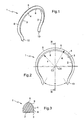
- la
figure 1 est une vue en perspective d'une bague de préhension utilisée dans le procédé selon l'invention ; - la
figure 2 est une vue en plan de la bague de lafigure 1 ; - la
figure 3 est une vue en coupe suivant la ligne III-III de lafigure 2 ; - la
figure 4 est une vue en perspective d'une bague de préhension selon une variante de réalisation ; - la
figure 5 est une vue en perspective illustrant la saisie d'une lentille ophtalmique au moyen d'un outillage classique et de la bague de préhension de lafigure 4 , en vue de son traitement par trempage. - En référence aux figures, et en particulier à la
figure 1 , la bague de préhension utilisée dans le procédé selon l'invention comporte un arceau 1 de cerclage du bord d'une lentille optique. - Cette lentille optique consiste en l'espèce, typiquement, en une lentille ophtalmique à la surface de laquelle on souhaite déposer une couche de vernis, comme cela sera mieux expliqué ultérieurement en référence à la
figure 4 . - L'arceau de cerclage 1 est alors destiné à se clipper autour de la lentille sur son chant. L'arceau 1 ne forme pas un cercle complet, mais présente une ouverture à la faveur de laquelle la bague peut être clippée sur l'élément optique. L'arceau 1 forme ainsi un arc de plus de 180 degrés, de préférence compris entre 250 et 320 degrés. Dans l'exemple illustré, particulièrement optimisé, l'arceau forme un arc de 300 degrés, avec une ouverture, notée alpha (α) sur la
figure 2 , de 60 degrés, à 10% près. - Pour cette fixation par cerclage clippé, l'arceau 1 est réalisé en un matériau élastiquement flexible. La raideur du matériau retenu doit résulter d'un compromis, pour assurer une fixation fiable de la bague avec la lentille, sans pour autant contraindre cette dernière. Aux essais, des résultats satisfaisants ont été obtenus avec un arceau exerçant sur la lentille un effort de maintien de l'ordre de quelques Newton. Aux essais, on a ainsi retenu, pour une lentille d'un diamètre de 65 mm, un effort compris entre 3 et 8 N.
- Ce matériau doit en outre résister aux traitements qu'il est destiné à subir avec les lentilles qu'il sera amené à équiper et rester inerte vis-à-vis de ces traitements. Il faut en particulier rechercher une bonne tenue mécanique en température, sans effondrement du module d'Young jusqu'à des températures de l'ordre de 100°C, ainsi qu'une bonne résistance chimique aux solutions basiques chaudes, solvants alcooliques, cetone, etc. Il est préférable que la température de fusion du matériau soit supérieure à 150°C et que la température de transition vitreuse soit supérieure à - 20°C. On pourra par exemple utiliser efficacement comme matériau constitutif de la bague un Polyamide 66 avec une température de fusion de l'ordre de 270°C et un module à température ambiante de 2840 MPa ou encore un polypropylène avec une température de fusion de 180°C, une température de transition vitreuse de -10°C et un module de 1000 à 1500 MPa à température ambiante.
- L'arceau de cerclage 1 présente une face intérieure 2 destinée à entrer en contact avec le bord de l'élément optique, c'est-à-dire en l'espèce le chant de la lentille. Cette face intérieure 2 est longitudinalement continue au second ordre. Elle est donc dépourvue d'arrête vive transversale, ce qui favorise l'écoulement longitudinal du vernis au sortir du bain, comme cela sera mieux expliqué ultérieurement.
- En revanche, on observe que l'arceau 1 présente extérieurement et latéralement des arrêtes longitudinales vives 3, 4, 5 en forme d'arcs de cercles, destinées à favoriser et canaliser l'écoulement de matière liquide et, partant, améliorer la qualité du drainage recherché au sortir du bain de traitement.
- Plus précisément, la face intérieure 2 de l'arceau 1 est ici cylindrique et se raccorde par les deux arrêtes 3 (dont une seule est visible aux
figures 1 et 2 ) à deux flancs plats 8 auxquels se raccorde une face extérieure 9 réalisée en deux parties de forme convexe, par exemple conique ou torique, réunies par l'arrête 5 formant une ligne de crête. - En référence à la
figure 3 , l'arceau de cerclage et de drainage 1 est ainsi formé d'un profilé dont la section présente un côté intérieur correspondant à la face intérieure 2 de contact avec l'élément optique, un côté extérieur en forme d'arc brisé, correspondant à la face extérieure 9 et présentant un sommet anguleux correspondant à l'arrête 5, et deux côtés latéraux correspondant aux flancs 8 et raccordés au côté intérieur et au côté extérieur par deux points anguleux correspondant respectivement aux arrêtes 3 et 4. Au repos, le brin neutre de l'arceau 1 présente, globalement, une forme d'arc de cercle. - L'arceau de cerclage 1 possède, au repos, un diamètre intérieur correspondant au diamètre de la face intérieure 2, noté r sur la
figure 2 , et un diamètre extérieur, noté R, et correspondant au diamètre de l'arrête de sommet 5. Le centre C2 de l'arrête 2 est légèrement décalé vers le bas, en direction de l'ouverture alpha (α), par rapport au centre C5 de l'arrête 5. Les arrêtes 4 et 5 étant concentriques, l'arrête 3 rejoint tangentiellement l'arrête 4. En l'espèce, pour la préhension de lentilles présentant classiquement un diamètre de 65 mm, on a retenu les valeurs suivantes : r = 28,5 mm et R = 32,5 mm. - La bague est en outre pourvue, à chacune des deux extrémités libres de l'arceau de cerclage 1, d'un bec d'égouttement 10 tourné vers l'extérieur.
- Les becs d'égouttement présentent une face intérieure prolongeant celle de l'arceau de cerclage 1 avec une continuité longitudinale de second ordre.
- Comme cela est mieux visible sur la
figure 2 , les extrémités libres des becs d'égouttement sont biseautées, afin de faciliter l'évacuation par gravité des gouttes de matière. Dans l'exemple illustré, les biseaux d'extrémité ainsi ménagés forment entre eux un dièdre présentant un angle au sommet égal à l'angle d'ouverture alpha (α). - Les
figures 4 et 5 illustrent une variante d'exécution d'une bague utilisée dans le procédé selon l'invention. Comme précédemment, cette bague comporte un arceau ouvert 20 pourvu à ces extrémités libres de becs d'égouttement 30 pointant vers le bas. - Dans cette variante, l'arceau 20 possède des faces intérieure 21 et extérieure 27 concaves et des flancs plats 25. Plus précisément, comme cela est mieux visible sur la
figure 5 , le côté intérieur de la section de l'arceau 20, correspondant à la face intérieure 21, est en forme d'arc de cercle en renfoncement et se raccorde directement aux côtés latéraux, correspondant aux flancs 25, avec des angles vifs. Le côté extérieur de la section de l'arceau 20, correspondant à la face extérieure 27, comporte une partie centrale principale en forme d'arc de cercle en renfoncement, se raccordant aux côtés latéraux 25 par l'intermédiaire de deux méplats 26 formant des angles vifs 23, 24 avec les côtés latéraux 25 et la partie centrale. - La face extérieure de l'arceau de cerclage possède deux portions de préhension striées 31, diamétralement opposées, globalement situées sur le diamètre horizontal de l'arceau 20.
- En service, comme cela est illustré par la
figure 6 , on utilise un outillage servant à la préhension de lentilles 100 en vue de leur manipulation et en particulier de leur immersion dans le bain de traitement. Cet outillage de préhension de type classique consiste ici, typiquement, en un panier 200 capable d'accueillir simultanément plusieurs lentilles 100 et offrant pour chacune d'elles trois zones d'appui, avec deux zones de saisie latérales et une zone d'appui inférieure. - Chaque lentille 100 est préalablement pourvue d'une bague de préhension telle que la bague 20 précédemment décrite.
- Pour l'accueil de chaque lentille 100, le panier 200 comporte une pince à deux branches 201, 202 saisissant la bague 20 de chaque lentille 100 par sa face extérieure, les portions striées 31 coopérant en leur offrant prise avec des griffes coudées 203, 204 ménagées à l'extrémité des pinces 201, 202. Un socle 205 offre un appui direct à la tranche de la lentille 100 dans sa partie inférieure.
Claims (11)
- Procédé de traitement par trempage d'un élément optique, dans lequel l'élément optique est maintenu, lors de son trempage, dans une bague de préhension comportant un arceau (1 ;20) de drainage et de cerclage du bord de l'élément optique, formant un arc de plus de 180 degrés et pourvu, à chacune de ses deux extrémités, d'un bec d'égouttement (10 ;30) tourné vers l'extérieur.
- Procédé selon la revendication précédente, dans lequel l'arceau (1 ;20) présente une face intérieure (2 ;21) de contact avec le bord de l'élément optique, qui est longitudinalement continue au second ordre.
- Procédé selon la revendication précédente, dans lequel les becs d'égouttement (10 ;30) présentent une face intérieure prolongeant celle de l'arceau avec une continuité longitudinale de second ordre.
- Procédé selon l'une des revendications précédentes, dans lequel l'arceau (1 ;20) forme un arc compris entre 220 et 280 degrés.
- Procédé selon la revendication précédente, dans lequel l'arceau (1 ;20) forme un arc de 250 degrés à 10% près.
- Procédé selon l'une des revendications précédentes, dans lequel l'arceau (1 ;20) est élastiquement flexible.
- Procédé selon l'une des revendications précédentes, dans lequel les extrémités libres des becs d'égouttement (10 ;30) sont biseautées.
- Procédé selon l'une des revendications précédentes, dans lequel l'arceau (1 ;20) est formé d'un profilé dont la section présente un côté intérieur de contact avec l'élément optique, un côté extérieur et deux côtés latéraux (8 ; 25), l'un au moins des côtés intérieur et extérieur de la section de l'arceau (1 ;20) se raccorde aux côtés latéraux (8 ; 25) avec des angles vifs.
- Procédé selon la revendication précédente, dans lequel l'un au moins des côtés intérieur et extérieur de la section de l'arceau (20) est ménagé en renfoncement.
- Procédé selon l'une des revendications précédentes, dans lequel l'arceau (20) de cerclage présente une face extérieure possédant deux portions de préhension striées (31) diamétralement opposées.
- Procédé selon l'une des revendications précédentes, dans lequel la bague de préhension est, lors de son trempage, orientée de telle sorte que ses deux becs d'égouttement (10 ;30) pointent vers le bas.
Applications Claiming Priority (2)
| Application Number | Priority Date | Filing Date | Title |
|---|---|---|---|
| FR0400110A FR2865043B1 (fr) | 2004-01-08 | 2004-01-08 | Bague de prehension d'une lentille optique en vue de son traitement par trempage |
| PCT/FR2004/002970 WO2005075108A1 (fr) | 2004-01-08 | 2004-11-22 | Bague de prehension d'une lentille optique en vue de son traitement par trempage |
Publications (2)
| Publication Number | Publication Date |
|---|---|
| EP1703993A1 EP1703993A1 (fr) | 2006-09-27 |
| EP1703993B1 true EP1703993B1 (fr) | 2010-04-21 |
Family
ID=34684870
Family Applications (1)
| Application Number | Title | Priority Date | Filing Date |
|---|---|---|---|
| EP04805501A Expired - Lifetime EP1703993B1 (fr) | 2004-01-08 | 2004-11-22 | Procede de traitement par trempage d'elements optiques |
Country Status (6)
| Country | Link |
|---|---|
| US (2) | US20090188429A1 (fr) |
| EP (1) | EP1703993B1 (fr) |
| AT (1) | ATE464952T1 (fr) |
| DE (1) | DE602004026779D1 (fr) |
| FR (1) | FR2865043B1 (fr) |
| WO (1) | WO2005075108A1 (fr) |
Families Citing this family (4)
| Publication number | Priority date | Publication date | Assignee | Title |
|---|---|---|---|---|
| EP1914579A1 (fr) | 2006-10-18 | 2008-04-23 | ESSILOR INTERNATIONAL Compagnie Générale d'Optique | Dispositif de maintien de verres d'optique permettant la manutention durant la fabrication. |
| DE102008022211B3 (de) * | 2008-05-06 | 2010-02-25 | Carl Zeiss Surgical Gmbh | Linsenträger sowie optische Baugruppe |
| US9446428B2 (en) | 2010-12-16 | 2016-09-20 | Essilor International (Compagnie Generale D'optique) | Method of dip-coating a segmented multifocal lens |
| DE102012211671B4 (de) * | 2012-07-04 | 2019-11-14 | Carl Zeiss Meditec Ag | Ophthalmoskopierlupe |
Family Cites Families (7)
| Publication number | Priority date | Publication date | Assignee | Title |
|---|---|---|---|---|
| FR1121357A (fr) * | 1955-03-25 | 1956-08-13 | Dispositif de fixation de tubes de canalisations sanitaires, électriques, etc., sur une paroi | |
| DE1728469U (de) * | 1956-06-07 | 1956-08-23 | Baberg & Co | Halter fuer isolatoren an stangen, rohren od. dgl. |
| GB1361113A (en) * | 1973-04-11 | 1974-07-24 | Ventolite Nsg Ltd | Clips |
| US5149158A (en) * | 1989-11-20 | 1992-09-22 | Submicron Systems, Inc. | Wafer carrier holder for wafer carriers |
| TW358472U (en) * | 1995-11-27 | 1999-05-11 | Samsung Electronics Co Ltd | Wafer carrier with an anti-slip surface |
| JP4572314B2 (ja) * | 2000-02-25 | 2010-11-04 | セイコーエプソン株式会社 | 光学部品用保持具およびこれを用いた眼鏡レンズの製造方法 |
| JP3838227B2 (ja) * | 2002-08-06 | 2006-10-25 | セイコーエプソン株式会社 | レンズ保持治具 |
-
2004
- 2004-01-08 FR FR0400110A patent/FR2865043B1/fr not_active Expired - Fee Related
- 2004-11-22 DE DE602004026779T patent/DE602004026779D1/de not_active Expired - Lifetime
- 2004-11-22 EP EP04805501A patent/EP1703993B1/fr not_active Expired - Lifetime
- 2004-11-22 WO PCT/FR2004/002970 patent/WO2005075108A1/fr not_active Ceased
- 2004-11-22 AT AT04805501T patent/ATE464952T1/de not_active IP Right Cessation
- 2004-11-22 US US10/585,400 patent/US20090188429A1/en not_active Abandoned
-
2010
- 2010-11-30 US US12/956,257 patent/US9114419B2/en not_active Expired - Fee Related
Also Published As
| Publication number | Publication date |
|---|---|
| FR2865043B1 (fr) | 2006-03-10 |
| EP1703993A1 (fr) | 2006-09-27 |
| WO2005075108A1 (fr) | 2005-08-18 |
| US20110070364A1 (en) | 2011-03-24 |
| WO2005075108A8 (fr) | 2006-07-06 |
| DE602004026779D1 (de) | 2010-06-02 |
| US20090188429A1 (en) | 2009-07-30 |
| FR2865043A1 (fr) | 2005-07-15 |
| ATE464952T1 (de) | 2010-05-15 |
| US9114419B2 (en) | 2015-08-25 |
Similar Documents
| Publication | Publication Date | Title |
|---|---|---|
| EP1363151B1 (fr) | Support individuel de lentille optique | |
| FR2783055A1 (fr) | Support pour lentille optique, et son procede de mise en oeuvre | |
| EP2145857A1 (fr) | Procédé de fabrication d'une pièce micromécanique | |
| FR2865043A1 (fr) | Bague de prehension d'une lentille optique en vue de son traitement par trempage | |
| EP2692598B1 (fr) | Dispositif de connexion entre un bras d'essuyage et un balai d'essuyage | |
| EP2578376A1 (fr) | Pièce optique comprenant une ame et une pluralité de couches | |
| FR3145304A1 (fr) | Dispositif de dépose d’au moins une pastille adhésive sur un élément de véhicule automobile | |
| EP2480419B1 (fr) | Revêtement décoratif avec adhésif intégré pour véhicule de transport | |
| WO2009071859A2 (fr) | Dispositif de fixation au sol des elements de toiture d'un abri telescopique pour bassin de piscine | |
| FR2768237A1 (fr) | Attache de verre pour article de lunetterie, et article de lunetterie la comportant | |
| EP3226080B1 (fr) | Système de barillet pour pièce d'horlogerie | |
| FR2758892A1 (fr) | Cable a fibres optiques | |
| EP0463906B1 (fr) | Corps optiquement absorbant dans le domaine du visible et des infrarouges, et un procédé de fabrication | |
| FR2909546A1 (fr) | Pointe de micromanipulateur chirurgical,micromanipulateur chirurgical et procede de fabrication d'une pointe pour un tel micromanipulateur. | |
| EP1762372A1 (fr) | Dispositif pour la réalisation d'une lentille optique en matiére synthétique polymérisable | |
| FR2895524A1 (fr) | Lentille optique et procede mettant en oeuvre des moyens d'indexation angulaire | |
| EP0992316A1 (fr) | Dispositif manuel de correction du positionnement du corps d'une électro-broche par rapport à son support | |
| FR2579942A1 (en) | Fitting system for car roof lining | |
| FR3056153A1 (fr) | Unité vitrée avec pièce rapportée | |
| FR3151842A3 (fr) | Bouteille comportant un dispositif anti-gouttes perfectionné | |
| EP4081425A1 (fr) | Système d'essuyage pour véhicule automobile | |
| EP1410997A1 (fr) | Récipient en matière moulable muni d'une extrémité comportant une paroi multiple et son procédé de fabrication | |
| CH720313A1 (fr) | Coiffe de couronne de remontoir ou de poussoir. | |
| WO2025088379A1 (fr) | Pièce élastique pour charnière de monture de lunettes optiques ou solaires et charnière de monture de lunettes optiques ou solaires | |
| FR3059216A1 (fr) | Prehenseur pour un manche d'une brosse aspirante |
Legal Events
| Date | Code | Title | Description |
|---|---|---|---|
| PUAI | Public reference made under article 153(3) epc to a published international application that has entered the european phase |
Free format text: ORIGINAL CODE: 0009012 |
|
| 17P | Request for examination filed |
Effective date: 20060711 |
|
| AK | Designated contracting states |
Kind code of ref document: A1 Designated state(s): AT BE BG CH CY CZ DE DK EE ES FI FR GB GR HU IE IS IT LI LU MC NL PL PT RO SE SI SK TR |
|
| DAX | Request for extension of the european patent (deleted) | ||
| 17Q | First examination report despatched |
Effective date: 20081201 |
|
| RTI1 | Title (correction) |
Free format text: METHOD FOR IMMERSION PROCESSING OF OPTICAL ELEMENTS |
|
| GRAP | Despatch of communication of intention to grant a patent |
Free format text: ORIGINAL CODE: EPIDOSNIGR1 |
|
| GRAS | Grant fee paid |
Free format text: ORIGINAL CODE: EPIDOSNIGR3 |
|
| GRAA | (expected) grant |
Free format text: ORIGINAL CODE: 0009210 |
|
| AK | Designated contracting states |
Kind code of ref document: B1 Designated state(s): AT BE BG CH CY CZ DE DK EE ES FI FR GB GR HU IE IS IT LI LU MC NL PL PT RO SE SI SK TR |
|
| REG | Reference to a national code |
Ref country code: GB Ref legal event code: FG4D Free format text: NOT ENGLISH |
|
| REG | Reference to a national code |
Ref country code: CH Ref legal event code: EP |
|
| REG | Reference to a national code |
Ref country code: IE Ref legal event code: FG4D Free format text: LANGUAGE OF EP DOCUMENT: FRENCH |
|
| REF | Corresponds to: |
Ref document number: 602004026779 Country of ref document: DE Date of ref document: 20100602 Kind code of ref document: P |
|
| REG | Reference to a national code |
Ref country code: NL Ref legal event code: VDEP Effective date: 20100421 |
|
| PG25 | Lapsed in a contracting state [announced via postgrant information from national office to epo] |
Ref country code: SE Free format text: LAPSE BECAUSE OF FAILURE TO SUBMIT A TRANSLATION OF THE DESCRIPTION OR TO PAY THE FEE WITHIN THE PRESCRIBED TIME-LIMIT Effective date: 20100421 Ref country code: NL Free format text: LAPSE BECAUSE OF FAILURE TO SUBMIT A TRANSLATION OF THE DESCRIPTION OR TO PAY THE FEE WITHIN THE PRESCRIBED TIME-LIMIT Effective date: 20100421 Ref country code: ES Free format text: LAPSE BECAUSE OF FAILURE TO SUBMIT A TRANSLATION OF THE DESCRIPTION OR TO PAY THE FEE WITHIN THE PRESCRIBED TIME-LIMIT Effective date: 20100801 |
|
| REG | Reference to a national code |
Ref country code: IE Ref legal event code: FD4D |
|
| PG25 | Lapsed in a contracting state [announced via postgrant information from national office to epo] |
Ref country code: AT Free format text: LAPSE BECAUSE OF FAILURE TO SUBMIT A TRANSLATION OF THE DESCRIPTION OR TO PAY THE FEE WITHIN THE PRESCRIBED TIME-LIMIT Effective date: 20100421 Ref country code: FI Free format text: LAPSE BECAUSE OF FAILURE TO SUBMIT A TRANSLATION OF THE DESCRIPTION OR TO PAY THE FEE WITHIN THE PRESCRIBED TIME-LIMIT Effective date: 20100421 Ref country code: IS Free format text: LAPSE BECAUSE OF FAILURE TO SUBMIT A TRANSLATION OF THE DESCRIPTION OR TO PAY THE FEE WITHIN THE PRESCRIBED TIME-LIMIT Effective date: 20100821 Ref country code: SI Free format text: LAPSE BECAUSE OF FAILURE TO SUBMIT A TRANSLATION OF THE DESCRIPTION OR TO PAY THE FEE WITHIN THE PRESCRIBED TIME-LIMIT Effective date: 20100421 |
|
| PG25 | Lapsed in a contracting state [announced via postgrant information from national office to epo] |
Ref country code: CY Free format text: LAPSE BECAUSE OF FAILURE TO SUBMIT A TRANSLATION OF THE DESCRIPTION OR TO PAY THE FEE WITHIN THE PRESCRIBED TIME-LIMIT Effective date: 20100505 Ref country code: PL Free format text: LAPSE BECAUSE OF FAILURE TO SUBMIT A TRANSLATION OF THE DESCRIPTION OR TO PAY THE FEE WITHIN THE PRESCRIBED TIME-LIMIT Effective date: 20100421 Ref country code: GR Free format text: LAPSE BECAUSE OF FAILURE TO SUBMIT A TRANSLATION OF THE DESCRIPTION OR TO PAY THE FEE WITHIN THE PRESCRIBED TIME-LIMIT Effective date: 20100722 |
|
| PG25 | Lapsed in a contracting state [announced via postgrant information from national office to epo] |
Ref country code: DK Free format text: LAPSE BECAUSE OF FAILURE TO SUBMIT A TRANSLATION OF THE DESCRIPTION OR TO PAY THE FEE WITHIN THE PRESCRIBED TIME-LIMIT Effective date: 20100421 Ref country code: PT Free format text: LAPSE BECAUSE OF FAILURE TO SUBMIT A TRANSLATION OF THE DESCRIPTION OR TO PAY THE FEE WITHIN THE PRESCRIBED TIME-LIMIT Effective date: 20100823 Ref country code: IE Free format text: LAPSE BECAUSE OF FAILURE TO SUBMIT A TRANSLATION OF THE DESCRIPTION OR TO PAY THE FEE WITHIN THE PRESCRIBED TIME-LIMIT Effective date: 20100421 Ref country code: EE Free format text: LAPSE BECAUSE OF FAILURE TO SUBMIT A TRANSLATION OF THE DESCRIPTION OR TO PAY THE FEE WITHIN THE PRESCRIBED TIME-LIMIT Effective date: 20100421 |
|
| PLBE | No opposition filed within time limit |
Free format text: ORIGINAL CODE: 0009261 |
|
| STAA | Information on the status of an ep patent application or granted ep patent |
Free format text: STATUS: NO OPPOSITION FILED WITHIN TIME LIMIT |
|
| PG25 | Lapsed in a contracting state [announced via postgrant information from national office to epo] |
Ref country code: CZ Free format text: LAPSE BECAUSE OF FAILURE TO SUBMIT A TRANSLATION OF THE DESCRIPTION OR TO PAY THE FEE WITHIN THE PRESCRIBED TIME-LIMIT Effective date: 20100421 Ref country code: RO Free format text: LAPSE BECAUSE OF FAILURE TO SUBMIT A TRANSLATION OF THE DESCRIPTION OR TO PAY THE FEE WITHIN THE PRESCRIBED TIME-LIMIT Effective date: 20100421 Ref country code: SK Free format text: LAPSE BECAUSE OF FAILURE TO SUBMIT A TRANSLATION OF THE DESCRIPTION OR TO PAY THE FEE WITHIN THE PRESCRIBED TIME-LIMIT Effective date: 20100421 |
|
| 26N | No opposition filed |
Effective date: 20110124 |
|
| PG25 | Lapsed in a contracting state [announced via postgrant information from national office to epo] |
Ref country code: IT Free format text: LAPSE BECAUSE OF FAILURE TO SUBMIT A TRANSLATION OF THE DESCRIPTION OR TO PAY THE FEE WITHIN THE PRESCRIBED TIME-LIMIT Effective date: 20100421 |
|
| BERE | Be: lapsed |
Owner name: ESSILOR INTERNATIONAL (COMPAGNIE GENERALE D'OPTIQ Effective date: 20101130 |
|
| PG25 | Lapsed in a contracting state [announced via postgrant information from national office to epo] |
Ref country code: MC Free format text: LAPSE BECAUSE OF NON-PAYMENT OF DUE FEES Effective date: 20101130 |
|
| REG | Reference to a national code |
Ref country code: CH Ref legal event code: PL |
|
| PG25 | Lapsed in a contracting state [announced via postgrant information from national office to epo] |
Ref country code: LI Free format text: LAPSE BECAUSE OF NON-PAYMENT OF DUE FEES Effective date: 20101130 Ref country code: CH Free format text: LAPSE BECAUSE OF NON-PAYMENT OF DUE FEES Effective date: 20101130 |
|
| PG25 | Lapsed in a contracting state [announced via postgrant information from national office to epo] |
Ref country code: BE Free format text: LAPSE BECAUSE OF NON-PAYMENT OF DUE FEES Effective date: 20101130 |
|
| PG25 | Lapsed in a contracting state [announced via postgrant information from national office to epo] |
Ref country code: BG Free format text: LAPSE BECAUSE OF FAILURE TO SUBMIT A TRANSLATION OF THE DESCRIPTION OR TO PAY THE FEE WITHIN THE PRESCRIBED TIME-LIMIT Effective date: 20100421 Ref country code: HU Free format text: LAPSE BECAUSE OF FAILURE TO SUBMIT A TRANSLATION OF THE DESCRIPTION OR TO PAY THE FEE WITHIN THE PRESCRIBED TIME-LIMIT Effective date: 20101022 Ref country code: LU Free format text: LAPSE BECAUSE OF NON-PAYMENT OF DUE FEES Effective date: 20101122 |
|
| PG25 | Lapsed in a contracting state [announced via postgrant information from national office to epo] |
Ref country code: TR Free format text: LAPSE BECAUSE OF FAILURE TO SUBMIT A TRANSLATION OF THE DESCRIPTION OR TO PAY THE FEE WITHIN THE PRESCRIBED TIME-LIMIT Effective date: 20100421 |
|
| PG25 | Lapsed in a contracting state [announced via postgrant information from national office to epo] |
Ref country code: BG Free format text: LAPSE BECAUSE OF FAILURE TO SUBMIT A TRANSLATION OF THE DESCRIPTION OR TO PAY THE FEE WITHIN THE PRESCRIBED TIME-LIMIT Effective date: 20100721 |
|
| REG | Reference to a national code |
Ref country code: FR Ref legal event code: PLFP Year of fee payment: 12 |
|
| REG | Reference to a national code |
Ref country code: FR Ref legal event code: PLFP Year of fee payment: 13 |
|
| REG | Reference to a national code |
Ref country code: FR Ref legal event code: PLFP Year of fee payment: 14 |
|
| REG | Reference to a national code |
Ref country code: DE Ref legal event code: R082 Ref document number: 602004026779 Country of ref document: DE Representative=s name: 24IP LAW GROUP SONNENBERG FORTMANN, DE Ref country code: DE Ref legal event code: R081 Ref document number: 602004026779 Country of ref document: DE Owner name: ESSILOR INTERNATIONAL, FR Free format text: FORMER OWNER: ESSILOR INTERNATIONAL (COMPAGNIE GENERALE D'OPTIQUE), CHARENTON-LE-PONT, FR |
|
| REG | Reference to a national code |
Ref country code: GB Ref legal event code: 732E Free format text: REGISTERED BETWEEN 20180517 AND 20180523 |
|
| REG | Reference to a national code |
Ref country code: FR Ref legal event code: TP Owner name: ESSILOR INTERNATIONAL, FR Effective date: 20180601 |
|
| PGFP | Annual fee paid to national office [announced via postgrant information from national office to epo] |
Ref country code: DE Payment date: 20191127 Year of fee payment: 16 |
|
| PGFP | Annual fee paid to national office [announced via postgrant information from national office to epo] |
Ref country code: FR Payment date: 20191125 Year of fee payment: 16 |
|
| PGFP | Annual fee paid to national office [announced via postgrant information from national office to epo] |
Ref country code: GB Payment date: 20191127 Year of fee payment: 16 |
|
| REG | Reference to a national code |
Ref country code: DE Ref legal event code: R119 Ref document number: 602004026779 Country of ref document: DE |
|
| GBPC | Gb: european patent ceased through non-payment of renewal fee |
Effective date: 20201122 |
|
| PG25 | Lapsed in a contracting state [announced via postgrant information from national office to epo] |
Ref country code: FR Free format text: LAPSE BECAUSE OF NON-PAYMENT OF DUE FEES Effective date: 20201130 |
|
| PG25 | Lapsed in a contracting state [announced via postgrant information from national office to epo] |
Ref country code: GB Free format text: LAPSE BECAUSE OF NON-PAYMENT OF DUE FEES Effective date: 20201122 Ref country code: DE Free format text: LAPSE BECAUSE OF NON-PAYMENT OF DUE FEES Effective date: 20210601 |
|
| P01 | Opt-out of the competence of the unified patent court (upc) registered |
Effective date: 20230525 |