EP1703857B1 - Stent reducing system - Google Patents
Stent reducing system Download PDFInfo
- Publication number
- EP1703857B1 EP1703857B1 EP04811192A EP04811192A EP1703857B1 EP 1703857 B1 EP1703857 B1 EP 1703857B1 EP 04811192 A EP04811192 A EP 04811192A EP 04811192 A EP04811192 A EP 04811192A EP 1703857 B1 EP1703857 B1 EP 1703857B1
- Authority
- EP
- European Patent Office
- Prior art keywords
- stent
- fluid
- chamber
- diameter
- cells
- Prior art date
- Legal status (The legal status is an assumption and is not a legal conclusion. Google has not performed a legal analysis and makes no representation as to the accuracy of the status listed.)
- Expired - Lifetime
Links
Images





Classifications
-
- A—HUMAN NECESSITIES
- A61—MEDICAL OR VETERINARY SCIENCE; HYGIENE
- A61F—FILTERS IMPLANTABLE INTO BLOOD VESSELS; PROSTHESES; DEVICES PROVIDING PATENCY TO, OR PREVENTING COLLAPSING OF, TUBULAR STRUCTURES OF THE BODY, e.g. STENTS; ORTHOPAEDIC, NURSING OR CONTRACEPTIVE DEVICES; FOMENTATION; TREATMENT OR PROTECTION OF EYES OR EARS; BANDAGES, DRESSINGS OR ABSORBENT PADS; FIRST-AID KITS
- A61F2/00—Filters implantable into blood vessels; Prostheses, i.e. artificial substitutes or replacements for parts of the body; Appliances for connecting them with the body; Devices providing patency to, or preventing collapsing of, tubular structures of the body, e.g. stents
- A61F2/95—Instruments specially adapted for placement or removal of stents or stent-grafts
-
- A—HUMAN NECESSITIES
- A61—MEDICAL OR VETERINARY SCIENCE; HYGIENE
- A61F—FILTERS IMPLANTABLE INTO BLOOD VESSELS; PROSTHESES; DEVICES PROVIDING PATENCY TO, OR PREVENTING COLLAPSING OF, TUBULAR STRUCTURES OF THE BODY, e.g. STENTS; ORTHOPAEDIC, NURSING OR CONTRACEPTIVE DEVICES; FOMENTATION; TREATMENT OR PROTECTION OF EYES OR EARS; BANDAGES, DRESSINGS OR ABSORBENT PADS; FIRST-AID KITS
- A61F2/00—Filters implantable into blood vessels; Prostheses, i.e. artificial substitutes or replacements for parts of the body; Appliances for connecting them with the body; Devices providing patency to, or preventing collapsing of, tubular structures of the body, e.g. stents
- A61F2/95—Instruments specially adapted for placement or removal of stents or stent-grafts
- A61F2/9522—Means for mounting a stent or stent-graft onto or into a placement instrument
-
- A—HUMAN NECESSITIES
- A61—MEDICAL OR VETERINARY SCIENCE; HYGIENE
- A61F—FILTERS IMPLANTABLE INTO BLOOD VESSELS; PROSTHESES; DEVICES PROVIDING PATENCY TO, OR PREVENTING COLLAPSING OF, TUBULAR STRUCTURES OF THE BODY, e.g. STENTS; ORTHOPAEDIC, NURSING OR CONTRACEPTIVE DEVICES; FOMENTATION; TREATMENT OR PROTECTION OF EYES OR EARS; BANDAGES, DRESSINGS OR ABSORBENT PADS; FIRST-AID KITS
- A61F2/00—Filters implantable into blood vessels; Prostheses, i.e. artificial substitutes or replacements for parts of the body; Appliances for connecting them with the body; Devices providing patency to, or preventing collapsing of, tubular structures of the body, e.g. stents
- A61F2/95—Instruments specially adapted for placement or removal of stents or stent-grafts
- A61F2/9522—Means for mounting a stent or stent-graft onto or into a placement instrument
- A61F2/9524—Iris-type crimpers
Definitions
- the present invention relates generally to stent loading and crimping systems which are configured for reduced frictional interface between a stent and one or more system component which contact the stent during the crimping and loading process.
- a stent is a generally tubular device that is used to support a bodily lumen.
- a stent is typically delivered to a desired bodily location via a catheter. Often the stent is loaded onto a portion of the catheter, such as a balloon or other region of the catheter shaft. In some stent delivery systems the stent is crimped to the catheter in order to minimize the profile of the stent on the catheter and to prevent undesired movement of the stent relative to the catheter shaft.
- a number of techniques for loading and contracting a stent to a catheter shaft or balloon are used.
- One such technique that is commonly used in the radiological suite involves hand crimping the stent to the balloon.
- a stent is placed over an uninflated balloon and then squeezed with the fingers until the stent is in intimate contact with the uninflated balloon.
- the technique is highly operator dependent and can affect stent profile and stent placement with respect to the balloon and radiopaque markers. It can also affect the dilatation length of the stent and lead to pinching of the balloon.
- the stent In many current stent loading operations particularly those involving self-expanding nitinol or shape memory stents the stent is dipped or sprayed with liquid nitrogen or other cooling agent in order for the stent to achieve a martensitic state. While in the martensitic state the stent is constrained via a crimper or other reducing device.
- the crimper comprises an adjustable stent diameter reducing chamber or opening through which the stent is advanced in order to uniformly reduce or compress the stent about its circumference.
- Stent crimpers may have a variety of configurations and mechanisms for providing the stent diameter reduction chamber.
- an iris type chamber wherein a plurality of members or blades are moved relative to the stent to reduce or expand the diameter of the chamber is described in U.S. 6,360,577
- a crimper having a chamber defined by a plurality of member which extend inward to contract the chamber in a "star" or other geometric configuration is described in U.S.
- a crimper having a pair of jaws or members that are moved relative to one another to reduce or expand the diameter of the chamber is described in U.S.6,387,117
- a crimper having one or more conical apertures which at least partially define the chamber is described in U.S. 5,992,000 .
- Crimpers having other configurations are also known.
- a mandrel or push rod is utilized to drive the stent through the closed iris into a stent delivery mechanism such as a catheter.
- the crimping members or blades will come into direct contact with the stent being crimped as the iris is closed radially inward about the stent.
- the blades are kept in direct contact with the stent in order to keep the stent in the reduced state prior to loading of the stent onto a catheter or other delivery system.
- the stent is then transferred from the iris onto the delivery system by advancing a push rod or mandrel through the closed iris. In order to expel the stent from the iris the longitudinal force exerted on the stent by the mandrel must be sufficient to disengage the stent from its contact with the blades.
- the force exerted by direct contact of the crimper blades on the stent as well as the act of pushing the stent out of the iris may have significant impact on any coating the stent may have even if the force is not excessive.
- the stent includes one or more therapeutic coatings (i. e. a drug coated stent)
- direct contact of the stent by the blades during reduction, and/or the frictional interface of the blades and the stent during expulsion of the stent from the iris may result in impairment of the coating thus reducing or negating its effectiveness.
- US 2003/019264 A1 discloses an apparatus for manipulating a medical device, in particular a stent.
- Said apparatus is formed of at least three coupled moveable blades which are disposed about a references circle to form an aperture the size of which may be varied.
- Each blade is in communication with an actuation device which is capable of moving the blade to alter the size of the aperture.
- the blades of said apparatus are cooled by a cooling fluid received from a fluid source.
- stent reducing/loading systems with the capability to reduce and expel a stent, especially those stents having a therapeutic coating, from the reducing mechanism with reduced force and preferably with reduced contact between the stent and the reducing mechanism and/or push rod or support mandrel.
- An existing crimper is provided with a fluid source to inject fluid into the stent reduction chamber through the existing gaps between the blades.
- the blades of a crimper are modified to provide slots through which fluid may be channeled into the chamber.
- the fluid is air.
- the invention comprises a mandrel which supports the stent as it is advanced through the stent diameter reducing chamber.
- the mandrel has a stepped diameter which allows the stent to be secured at one or more of its proximal and distal ends by a raised diameter portion or collar of the mandrel.
- the distal end of the mandrel is tapered to facilitate alignment of the mandrel with a stent delivery system such as a catheter.
- the mandrel is provided with a polymer coating.
- the mandrel defines a mandrel lumen.
- a fluid may be passed through the lumen to the stent and/or the chamber.
- the fluid passed through the lumen is liquid nitrogen, chilled air or a similar cooling composition.
- the crimper defines a stepped diameter chamber.
- a delivery system such as a catheter, may be partially inserted into the larger diameter stepped region of the closed chamber in order to precisely align the stent and/or mandrel with the delivery system.
- a vibratory mechanism is in communication with one or more components of a stent crimper and/or loading mandrel.
- the vibratory mechanism may apply vibratory energy to the crimper, loading mandrel, stent, and/or delivery system to aid in minimizing frictional interface therebetween.
- vibratory energy may also be selectively applied to the crimper following contraction of the stent to aid in releasing the stent from the blades.
- vibratory energy may also be selectively applied to the mandrel once the stent is properly positioned within the delivery system in order to aid in releasing the stent from the mandrel.
- the vibratory energy is delivered at an ultrasonic frequency.
- the present invention comprises embodiments which address the shortcomings described above.
- the present invention is embodied in a variety of forms.
- the invention is directed to a radial stent reducing assembly or crimper 10.
- Crimper 10 may have any configuration of contacting members and/or any configuration of stent diameter reducing chamber, such as has been described above.
- crimper 10 is provided with a plurality of stent reducing members or blades 12 which define a stent reduction chamber 14 into which a stent or other medical device 16 is positioned in order to reduce the stent 16 from an unreduced diameter state, such as is shown in FIG. 1 to a reduced diameter state as is shown in FIG. 2 .
- the crimper 10 in the embodiment shown in FIGs. 1-3 is constructed and arranged to form a fluid bearing 20 between the blades 12 and the stent 16 during the crimping or reducing process.
- the fluid bearing 20 is formed by a fluid such as air, water, coolant, etc., indicated by arrows 22 in FIG.
- Blades 12 may be constructed from one or more metals, polymers or combinations thereof.
- the fluid bearing 20 is established by injecting fluid 22 from a fluid source 30 into the crimper housing 18 by one or more ports 24.
- Each port 24 is in fluid communication with the one or more fluid passages 26 between and/or within each blade 12.
- Each fluid passage 26 leads into the chamber 14.
- fluid pressure is about 2 to about 20 psi.
- each member 34 may be configured as a simple fluid tight seal to prevent any fluid from escaping the chamber 14 during the crimping process.
- the members 34 may define a labyrinth passage which allows fluid 22 to escape the contracting chamber at a predetermined rate, in order to maintain a fluid bearing having a substantially constant pressure.
- the members 34 may define an opening therethrough which has a diameter less than that of the stent in the reduced state, in order to allow fluid 22 to pass from the chamber 14 which retaining the stent 16 therein.
- the members 34 may include one or more of the mechanisms described above as well as other mechanisms, such as adjustable valves, ports, seals, etc. for maintaining and/or regulating fluid pressure.
- fluid 22 is injected into the housing 18 through one or more ports 24.
- at least one port may be opened following the crimping process to allow the fluid 22 of the fluid bearing 20 to be purged from the chamber 14.
- the fluid 22 is a fluid or combination of fluids including, but not limited to air, carbon dioxide, water, nitrous oxide, nitrogen gas or any other fluid for use in forming a fluid bearing 20 between two surfaces.
- fluid 22 is a bead-like substance that acts in the manner of a ball bearing.
- fluid 22 may remain on the stent surface post loading.
- fluid 22 not only provides the fluid bearing 20, but where the fluid is cooled or is provided with a sufficiently low temperature, the fluid also acts to maintain a stent 16 constructed of a shape memory material, such as for example nitinol or other shape memory metals or polymers, in a martensitic state, thereby inhibiting the stent composition form transitioning to an austenitic phase.
- the fluid is cooled to a predetermined temperature sufficient to provide the stent with a phase transformation from austenitic state to martensitic state.
- the temperature is sufficient to reach the M f of Nitinol or other material from which the stent is constructed.
- the temperature of the fluid 22 is about -60° to about -80° Celsius.
- the fluid 22 has a temperature of just below the melting point of the polymer material.
- fluid 22 is injected into the chamber 14 through one or more fluid passages 26.
- fluid passages 26 may be defined by the space 28 between longitudinally displaced blades 12 such as are shown n FIG. 3 .
- the blades 12 are sized and shaped to define a space 28 radially between each blade 12 such as is shown in FIG. 4 .
- the spaces 28 act as fluid passages 26 to transport fluid 22 into the chamber 14.
- the fluid 22 form a fluid bearing 20 that effectively extends from the chamber 14 into the fluid passages 26, such as is best shown in FIG. 5 .
- wear resulting from contact between the blades is avoided as the fluid bearing 20 acts to not only prevent contact between the stent 16 and blades 12, but between the individual blades as well.
- the use of fluid 22 in forming a fluid bearing may be used in a variety of crimpers 10.
- the crimper 10 is provided with an annular fluid passage 26 which is in fluid communication with four fluid ports 24.
- the fluid 22 is injected into the passage 26 and flows into the chamber 14 via the spaces 28 between the blades 12, which in some embodiments may be provided for as a result of the natural tolerances resulting from the blades' construction.
- one or more of the blades 12 is especially constructed to include fluid passages 26 between the adjacent blades 12.
- a push rod or mandrel 40 may be inserted into an end 32 of the chamber 14 during or subsequent to the reduction of the stent 16.
- the mandrel may supplement or replace one of the seal members in order to ensure that the formation and performance of the fluid bearing 20 is not compromised by the mandrel's use.
- the fluid bearing 20 is maintained even during expulsion of the stent 16 from the chamber 14 by advancing the mandrel 40 therethrough.
- the reduced diameter stent 16 is loaded directly onto a catheter or other stent delivery system 50 by pushing the stent 16 through the chamber 14 and directly into the catheter's protective housing or sheath 52.
- the crimper 10 may have a chamber 14 with a stepped diameter, to allow the catheter 50 to be partially inserted within the chamber 14.
- the catheter receiving region 54 of the stepped diameter chamber 14 has a greater diameter than the stent reducing region 56.
- the inner diameter 58 of the catheter 50 is at least as large as the diameter of the stent reducing region 56 of the chamber 14.
- the stent 16 is reduced within the crimper 10 while mounted on a portion of the mandrel 40.
- the mandrel 40 has a tapered distal end portion 42 which has a diameter less than that of the inner diameter 58 of a catheter 50.
- the mandrel 40, including the reduced diameter stent 16 may be readily advanced into the catheter 50 with minimal or no contact between the stent 16 and the sheath 52.
- the mandrel 40 further comprises a proximal end portion 44 which defines an annular seal 46, the annular seal 46 has a diameter larger than that of the chamber 14 in the closed or reduced configuration.
- the annular seal 46 may supplement or replace the need for a fluid seal member 34 at one end 32 of the chamber 14.
- both the proximal end portion 44 and the distal end portion 42 of the mandrel 40 each comprise an annular seal 46.
- Each annular seal 46 acts as a fluid seal member, as described above.
- the fluid bearing 20 forms not only between the blades 12 and the stent 16, but also between the portion of the mandrel 40 about which the stent 16 is disposed and the stent 16. Such a dual layer fluid bearing 20 protects both the inside surface 60 and outside surface 62 of the stent 16 from extraneous contact.
- the mandrel 40 may define a fluid injection lumen 70 into which a fluid 22a may be injected.
- Mandrel 40 may further define one or more perfusion ports, openings, perforations or pores 72 through which the fluid 22a may pass from the lumen 70 and into the chamber 14.
- Fluid 22a injected into the chamber in this manner may be used to assist in forming the fluid bearing 20, and particularly a dual layer fluid bearing such as previously discussed.
- the fluid 22a passively, by cooling the mandrel 40, or actively, by directly flowing onto the stent 16, cools the stent 16 to a temperature sufficient to provide the stent with a phase transformation from austenitic to martensitic.
- the fluid 22a is cooled air, liquid nitrogen (nitrous oxide) or another suitable coolant.
- one or more blades 12, the mandrel 40 and/or the fluid 22 and/or 22a by be imparted with an ultrasonic or other form of vibratory energy in order to further facilitate minimization of the frictional interface between the stent 16 and the crimper 10 or any of its components.
- the stent 16 as shown in any of the various FIGs. 1-12 may include one or more coatings and/or other delivery mechanisms which comprise one or more therapeutic agents, cellular materials, polymeric agents, drugs, etc.
- a therapeutic agent may be a drug, a non-genetic agent, a genetic agent, etc.
- suitable non-genetic therapeutic agents include but a re not limited to: anti-thrombogenic agents such as heparin, heparin derivatives, urokinase, and PPack (dextrophenylalanine proline arginine chloromethylketone); anti-proliferative agents such as enoxaprin, angiopeptin, monoclonal antibodies capable of blocking smooth muscle cell proliferation, hirudin, and acetylsalicylic acid; anti-inflammatory agents such as dexamethasone, prednisolone, corticosterone, budesonide, estrogen, sulfasalazine, and mesalamine; antineoplastic/antiproliferative/anti-miotic agents such as paclitaxel, 5-fluorouracil, cisplatin, vinblastine, vincristine, epothilones, endo
- an agent may include but is not limited to: anti-sense DNA and RNA; DNA coding for anti-sense RNA, tRNA or rRNA to replace defective or deficient endogenous molecules; angiogenic factors including growth factors such as acidic and basic fibroblast growth factors, vascular endothelial growth factor, epidermal growth factor, transforming growth factor ⁇ and ⁇ , platelet-derived endothelial growth factor, platelet-derived growth factor, tumor necrosis factor ⁇ , hepatocyte growth factor and insulin like growth factor; cell cycle inhibitors including CD inhibitors, thymidine kinase ("TK”) and other agents useful for interfering with cell proliferation; at least one of the family of bone morphogenic proteins (“BMP's”) such as BMP-2, BMP-3, BMP-4, BMP-5, BMP-6 (Vgr-1), BMP-7 (OP-1), BMP-8, BMP-9, BMP-10, BMP-11, BMP-12, BMP-13
- BMP's bone morphogenic proteins
- BMP-2, BMP-3, BMP-4, BMP-5, BMP-6 and BMP-7 Any of BMP-2, BMP-3, BMP-4, BMP-5, BMP-6 and BMP-7; dimeric proteins such as homodimers, heterodimers, or combinations thereof, alone or together with other molecules; molecules capable of inducing an upstream or downstream effect of a BMP such as "hedgehog" proteins, or the DNA's encoding them and any combinations thereof.
- the cellular material may include but is not limited to: cells of human origin (autologous or allogeneic); cells of non-human origin (xenogeneic) and any combination thereof.
- cellular material include but are not limited to the following:
- a therapeutic agent comprises at least one polymer agent or coating
- the at least one coating may include but is not limited to: polycarboxylic acids; cellulosic polymers, including cellulose acetate and cellulose nitrate; gelatin; polyvinylpyrrolidone; cross-linked polyvinylpyrrolidone; polyanhydrides including maleic anhydride polymers; polyamides; polyvinyl alcohols; copolymers of vinyl monomers such as EVA; polyvinyl ethers; polyvinyl aromatics; polyethylene oxides; glycosaminoglycans; polysaccharides; polyesters including polyethylene terephthalate; polyacrylamides; polyethers; polyether sulfone; polycarbonate; polyalkylenes including polypropylene, polyethylene and high molecular weight polyethylene; halogenated polyalkylenes including polytetrafluoroethylene; polyuethanes; polyorthoesters; proteins; polypeptides; silicones; si
- An example of a suitable polymer agent or coating comprises block copolymers comprising at least one A block and at least one B block.
- the A blocks are preferably soft elastomeric blocks, which are based upon one or more polyolefins, or other polymer with a glass transition temperature at or below room temperature.
- the A blocks can be polyolefinic blocks having alternating quaternary and secondary carbons of the general formulation: -(CRR'-CH 2 ) n -, where R and R' are, independently, linear or branched aliphatic groups such as methyl, ethyl, propyl, isopropyl, butyl, isobutyl and so forth, or represent cyclic aliphatic groups such as cyclohexane, cyclopentane, and the like, either with or without pendant groups.
- Preferred polyolefinic blocks include polymeric blocks of isobutylene, (i.e., polymers where R and R' are methyl groups).
- Other examples of A blocks include silicone rubber blocks and acrylate rubber blocks.
- the B blocks are preferably hard thermoplastic blocks with glass transition temperatures significantly higher than the elastomeric A blocks which, when combined with the soft A blocks, are capable of, inter alia , altering or adjusting the hardness of the resulting copolymer to achieve a desired combination of qualities.
- B blocks include polymers of methacrylates or polymers of vinyl aromatics.
- B blocks include blocks that are (a) formed from monomers of styrene styrene derivatives (e.g., ⁇ -methylstyrene, ring-alkylated styrenes or ring-halogenated styrenes or other substituted styrenes where one or more substituents are present on the aromatic ring) or mixtures of the same, collectively referred to herein as “styrenic blocks” or “polystyrenic blocks” or are (b) formed from monomers of methylmethacrylate, ethylmethacrylate, hydroxyethyl methacrylate or mixtures of the same.
- styrene styrene derivatives e.g., ⁇ -methylstyrene, ring-alkylated styrenes or ring-halogenated styrenes or other substituted styrenes where one or more substituents are present on the aromatic
- the block copolymers are provided in a variety of architectures, including cyclic, linear, and branched architectures.
- Branched architectures include star-shaped architectures (e.g., architectures in which three or more chains emanate from a single region), comb architectures (e.g., copolymers having a main chain and a plurality of side chains), and dendritic architectures (including arborescent or hyperbranched copolymers).
- block copolymers include the following: (a) BA (linear diblock), (b) BAB or ABA (linear triblock), (c) B(AB) n or A(BA) n (linear alternating block), or (d) X-(AB) n or X-(BA) n (includes diblock, triblock and other radial block copolymers), where n is a positive whole number and X is a starting seed, or initiator, molecule.
- Other examples of block polymers include branched block copolymers such as dendritic block copolymers, wherein at least one of the A and B blocks is branched, for instance, where the A blocks are branched and are capped by the B blocks.
- the device may also be provided with a sugar or more generally a carbohydrate and/or a gelatin to maintain the inventive medical devices on a balloon during delivery of the medical device to a desired bodily location.
- a sugar or more generally a carbohydrate and/or a gelatin to maintain the inventive medical devices on a balloon during delivery of the medical device to a desired bodily location.
- suitable compounds for treating the inventive medical devices include biodegradable polymers and polymers which are dissolvable in bodily fluids. Portions of the interior and/or exterior of the inventive medical devices may be coated or impregnated with the compound.
- Mechanical retention devices may also be used to maintain the inventive medical devices on the balloon during delivery.
- the device may also be provided in whole or in part with one or more of the above therapeutic agents, polymeric coatings or the like. Where multiple therapeutic agents are provided, different coatings and/or mechanisms may release the drugs at different rates. For example, one therapeutic agent may be released at a fast rate and another therapeutic agent may be released at a slow rate. Where multiple polymeric coatings are provided, the coatings may degrade or erode at different rates.
Landscapes
- Health & Medical Sciences (AREA)
- Engineering & Computer Science (AREA)
- Biomedical Technology (AREA)
- Cardiology (AREA)
- Oral & Maxillofacial Surgery (AREA)
- Transplantation (AREA)
- Heart & Thoracic Surgery (AREA)
- Vascular Medicine (AREA)
- Life Sciences & Earth Sciences (AREA)
- Animal Behavior & Ethology (AREA)
- General Health & Medical Sciences (AREA)
- Public Health (AREA)
- Veterinary Medicine (AREA)
- Prostheses (AREA)
- Materials For Medical Uses (AREA)
- Media Introduction/Drainage Providing Device (AREA)
Abstract
Description
- The present invention relates generally to stent loading and crimping systems which are configured for reduced frictional interface between a stent and one or more system component which contact the stent during the crimping and loading process.
- A stent is a generally tubular device that is used to support a bodily lumen. A stent is typically delivered to a desired bodily location via a catheter. Often the stent is loaded onto a portion of the catheter, such as a balloon or other region of the catheter shaft. In some stent delivery systems the stent is crimped to the catheter in order to minimize the profile of the stent on the catheter and to prevent undesired movement of the stent relative to the catheter shaft.
- A number of techniques for loading and contracting a stent to a catheter shaft or balloon are used. One such technique that is commonly used in the radiological suite involves hand crimping the stent to the balloon. A stent is placed over an uninflated balloon and then squeezed with the fingers until the stent is in intimate contact with the uninflated balloon. The technique is highly operator dependent and can affect stent profile and stent placement with respect to the balloon and radiopaque markers. It can also affect the dilatation length of the stent and lead to pinching of the balloon.
- Other technique for crimping stents involve the use of mechanical devices for crimping stents. Mechanical stent crimpers have been disclosed in a number of patents including
US 6,387,118 ;US 6,360,577 ;US 6,108,886 ;US 6,092,273 ;US 6,082,990 ;US 6,074,381 ;US 6,063,102 andUS 5,992,000 . - In many current stent loading operations particularly those involving self-expanding nitinol or shape memory stents the stent is dipped or sprayed with liquid nitrogen or other cooling agent in order for the stent to achieve a martensitic state. While in the martensitic state the stent is constrained via a crimper or other reducing device. In some cases the crimper comprises an adjustable stent diameter reducing chamber or opening through which the stent is advanced in order to uniformly reduce or compress the stent about its circumference.
- Stent crimpers may have a variety of configurations and mechanisms for providing the stent diameter reduction chamber. For example, an iris type chamber wherein a plurality of members or blades are moved relative to the stent to reduce or expand the diameter of the chamber is described in
U.S. 6,360,577 , a crimper having a chamber defined by a plurality of member which extend inward to contract the chamber in a "star" or other geometric configuration is described inU.S. 6,168,921 , a crimper having a pair of jaws or members that are moved relative to one another to reduce or expand the diameter of the chamber is described inU.S.6,387,117 , and a crimper having one or more conical apertures which at least partially define the chamber is described inU.S. 5,992,000 . Crimpers having other configurations are also known. - In many crimper assemblies a mandrel or push rod is utilized to drive the stent through the closed iris into a stent delivery mechanism such as a catheter.
- In many crimper designs however, the crimping members or blades will come into direct contact with the stent being crimped as the iris is closed radially inward about the stent. After the stent has been reduced in diameter, in many instances the blades are kept in direct contact with the stent in order to keep the stent in the reduced state prior to loading of the stent onto a catheter or other delivery system. The stent is then transferred from the iris onto the delivery system by advancing a push rod or mandrel through the closed iris. In order to expel the stent from the iris the longitudinal force exerted on the stent by the mandrel must be sufficient to disengage the stent from its contact with the blades. If the force exerted on the stent by the mandrel is greater than the column strength of the stent the stent will buckle thereby leading to an unsuccessful loading of the stent. Unfortunately, such excessive force is often required to remove the stent from the crimper.
- In addition to potentially buckling the stent, the force exerted by direct contact of the crimper blades on the stent as well as the act of pushing the stent out of the iris may have significant impact on any coating the stent may have even if the force is not excessive. For example where the stent includes one or more therapeutic coatings (i. e. a drug coated stent), direct contact of the stent by the blades during reduction, and/or the frictional interface of the blades and the stent during expulsion of the stent from the iris, may result in impairment of the coating thus reducing or negating its effectiveness.
-
US 2003/019264 A1 discloses an apparatus for manipulating a medical device, in particular a stent. Said apparatus is formed of at least three coupled moveable blades which are disposed about a references circle to form an aperture the size of which may be varied. Each blade is in communication with an actuation device which is capable of moving the blade to alter the size of the aperture. The blades of said apparatus are cooled by a cooling fluid received from a fluid source. - In light of the above it is the technical problem of the present invention to provide stent reducing/loading systems with the capability to reduce and expel a stent, especially those stents having a therapeutic coating, from the reducing mechanism with reduced force and preferably with reduced contact between the stent and the reducing mechanism and/or push rod or support mandrel.
- The above problem is solved by the subject-matter as defined in independent claim 1. Modifications and further developments of the present invention are derivable from the specification, the accompanying drawings and the claims.
- An existing crimper is provided with a fluid source to inject fluid into the stent reduction chamber through the existing gaps between the blades. In some embodiments the blades of a crimper are modified to provide slots through which fluid may be channeled into the chamber.
- In at least one embodiment the fluid is air.
- In at least one embodiment the invention comprises a mandrel which supports the stent as it is advanced through the stent diameter reducing chamber. In some embodiments the mandrel has a stepped diameter which allows the stent to be secured at one or more of its proximal and distal ends by a raised diameter portion or collar of the mandrel. In some embodiments the distal end of the mandrel is tapered to facilitate alignment of the mandrel with a stent delivery system such as a catheter. In some embodiments the mandrel is provided with a polymer coating.
- In at least one embodiment the mandrel defines a mandrel lumen. A fluid may be passed through the lumen to the stent and/or the chamber. In some embodiments the fluid passed through the lumen is liquid nitrogen, chilled air or a similar cooling composition.
- In at least one embodiment the crimper defines a stepped diameter chamber. When the chamber is in the closed position about the stent a delivery system, such as a catheter, may be partially inserted into the larger diameter stepped region of the closed chamber in order to precisely align the stent and/or mandrel with the delivery system.
- In at least one embodiment of the invention a vibratory mechanism is in communication with one or more components of a stent crimper and/or loading mandrel. The vibratory mechanism may apply vibratory energy to the crimper, loading mandrel, stent, and/or delivery system to aid in minimizing frictional interface therebetween. In some embodiments vibratory energy may also be selectively applied to the crimper following contraction of the stent to aid in releasing the stent from the blades. In some embodiments vibratory energy may also be selectively applied to the mandrel once the stent is properly positioned within the delivery system in order to aid in releasing the stent from the mandrel. In some embodiments the vibratory energy is delivered at an ultrasonic frequency.
- These and other embodiments which characterize the invention are pointed out with particularity in the claims annexed hereto and forming a part hereof. However, for a better understanding of the invention, its advantages and objectives obtained by its use, reference should be made to the drawings which form a further part hereof and the accompanying descriptive matter, in which there is illustrated and described embodiments of the invention.
- A detailed description of the invention is hereafter described with specific reference being made to the drawings in which:
-
FIG. 1 is a perspective view of an embodiment of the invention wherein the stent reduction chamber is shown in the open or pre-reduction state. -
FIG. 2 is a perspective view of the embodiment shown inFIG. 1 wherein the chamber is shown in the closed or reduced state. -
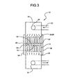
FIG. 3 is a partial cross-sectional side view of the embodiment shown inFIG. 2 . -
FIG. 4 is a partial close-up view of a portion of the embodiment shown inFIG. 2 and3 . -
FIG. 5 is a partial close-up view of the embodiment depicted inFIG.4 illustrating the fluid bearing between the stent and crimper. -
FIG. 6 is a partial cross-sectional end view of an iris configuration of the embodiment shown inFIGs 2 and3 . -
FIG. 7 is a partial cross-sectional end view of an iris configuration of the embodiment shown inFIGs 2 and3 wherein the crimping blades are provided with fluid passages. -
FIG. 8 is a partial close-up, cross-sectional side view of the embodiment shown inFIGs. 2 and3 wherein the stent is shown being expelled from the crimper using a push rod or mandrel. -
FIG. 9 is a partial close-up view of the embodiment depicted inFIG.8 illustrating the loading of a stent into a stent delivery catheter wherein the crimper is provided with a stepped diameter reducing chamber. -
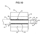
FIG. 10 is a partial cross-sectional side view of the embodiment shown inFIG. 8 wherein the stent is mounted on a configuration of the mandrel during the crimping process. -
FIG. 11 is a partial cross-sectional side view of the embodiment shown inFIG. 8 wherein the stent is mounted on a configuration of the mandrel during the crimping process. -
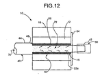
FIG. 12 is a partial cross-sectional side view of the embodiment shown inFIG. 8 wherein the stent is mounted on a configuration of the mandrel during the crimping process. - As is depicted in the various
FIGs. 1-12 , the present invention comprises embodiments which address the shortcomings described above. - As indicated above, the present invention is embodied in a variety of forms. In at least one embodiment, such as for example in the embodiment depicted in
FIG. 1 , the invention is directed to a radial stent reducing assembly orcrimper 10.Crimper 10 may have any configuration of contacting members and/or any configuration of stent diameter reducing chamber, such as has been described above. - In the embodiment shown,
crimper 10 is provided with a plurality of stent reducing members orblades 12 which define astent reduction chamber 14 into which a stent or othermedical device 16 is positioned in order to reduce thestent 16 from an unreduced diameter state, such as is shown inFIG. 1 to a reduced diameter state as is shown inFIG. 2 . Unlike many prior stent crimping devices, thecrimper 10 in the embodiment shown inFIGs. 1-3 is constructed and arranged to form afluid bearing 20 between theblades 12 and thestent 16 during the crimping or reducing process. Thefluid bearing 20 is formed by a fluid such as air, water, coolant, etc., indicated byarrows 22 inFIG. 3 , which is injected into thechamber 14 through theblades 12 or through one or more passages therein and/or therebetween, such as is shown inFIG. 3 . The presence of afluid bearing 20 between theblades 12 and thestent 16 ensures that the stent 1 6 is not directly contacted by theblades 12 of the closingchamber 14 during the crimping process. -
Blades 12 may be constructed from one or more metals, polymers or combinations thereof. - As is shown in
FIGs. 1-2 , thefluid bearing 20 is established by injectingfluid 22 from afluid source 30 into thecrimper housing 18 by one ormore ports 24. Eachport 24 is in fluid communication with the one or morefluid passages 26 between and/or within eachblade 12. Eachfluid passage 26 leads into thechamber 14. By injecting fluid into thechamber 14 under pressure, and substantially maintaining the fluid pressure within thechamber 14 during the crimping process, afluid bearing 20 is formed between theblades 12 and thestent 16. In some embodiments fluid pressure is about 2 to about 20 psi. - In order to maintain the fluid pressure necessary to form the
fluid bearing 20, the open ends 32 of thechamber 14 may be provided with one or more removableend seal members 34, such as is shown inFIG. 3 .Seal members 34, be configured to include a variety of mechanisms. For example eachmember 34 may be configured as a simple fluid tight seal to prevent any fluid from escaping thechamber 14 during the crimping process. In some embodiments themembers 34 may define a labyrinth passage which allowsfluid 22 to escape the contracting chamber at a predetermined rate, in order to maintain a fluid bearing having a substantially constant pressure. In some embodiments themembers 34 may define an opening therethrough which has a diameter less than that of the stent in the reduced state, in order to allowfluid 22 to pass from thechamber 14 which retaining thestent 16 therein. Themembers 34 may include one or more of the mechanisms described above as well as other mechanisms, such as adjustable valves, ports, seals, etc. for maintaining and/or regulating fluid pressure. - In some embodiments fluid 22 is injected into the
housing 18 through one ormore ports 24. In at least one embodiment, at least one port may be opened following the crimping process to allow thefluid 22 of thefluid bearing 20 to be purged from thechamber 14. - In some embodiments the fluid 22 is a fluid or combination of fluids including, but not limited to air, carbon dioxide, water, nitrous oxide, nitrogen gas or any other fluid for use in forming a
fluid bearing 20 between two surfaces. In at least oneembodiment fluid 22 is a bead-like substance that acts in the manner of a ball bearing. In some embodiments fluid 22 may remain on the stent surface post loading. - In some
embodiment fluid 22 not only provides thefluid bearing 20, but where the fluid is cooled or is provided with a sufficiently low temperature, the fluid also acts to maintain astent 16 constructed of a shape memory material, such as for example nitinol or other shape memory metals or polymers, in a martensitic state, thereby inhibiting the stent composition form transitioning to an austenitic phase. In some embodiments the fluid is cooled to a predetermined temperature sufficient to provide the stent with a phase transformation from austenitic state to martensitic state. In some embodiments the temperature is sufficient to reach the Mf of Nitinol or other material from which the stent is constructed. In at least one embodiment the temperature of the fluid 22 is about -60° to about -80° Celsius. In an embodiment where thestent 16 is constructed of one or more polymers the fluid 22 has a temperature of just below the melting point of the polymer material. - As indicated above,
fluid 22 is injected into thechamber 14 through one or morefluid passages 26. In some embodiments,fluid passages 26 may be defined by the space 28 between longitudinally displacedblades 12 such as are shown nFIG. 3 . In some embodiments theblades 12 are sized and shaped to define a space 28 radially between eachblade 12 such as is shown inFIG. 4 . When theblades 12 are contracted to reduce thechamber 14, such as is shown, the spaces 28 act asfluid passages 26 to transport fluid 22 into thechamber 14. In the configuration shown inFIG. 4 , the fluid 22 form afluid bearing 20 that effectively extends from thechamber 14 into thefluid passages 26, such as is best shown inFIG. 5 . As a result, in this embodiment, wear resulting from contact between the blades is avoided as the fluid bearing 20 acts to not only prevent contact between thestent 16 andblades 12, but between the individual blades as well. - As indicated above, the use of
fluid 22 in forming a fluid bearing may be used in a variety ofcrimpers 10. In the embodiment shown inFIG. 6 for example, thecrimper 10 is provided with anannular fluid passage 26 which is in fluid communication with fourfluid ports 24. The fluid 22 is injected into thepassage 26 and flows into thechamber 14 via the spaces 28 between theblades 12, which in some embodiments may be provided for as a result of the natural tolerances resulting from the blades' construction. In at least one embodiment, an example of which is shown inFIG. 7 one or more of theblades 12 is especially constructed to includefluid passages 26 between theadjacent blades 12. - As is shown in
FIG. 8 , in some embodiments a push rod ormandrel 40 may be inserted into anend 32 of thechamber 14 during or subsequent to the reduction of thestent 16. The mandrel may supplement or replace one of the seal members in order to ensure that the formation and performance of thefluid bearing 20 is not compromised by the mandrel's use. In order to maximize the benefit of reducing contact between theblades 12 and thestent 16, in some embodiments thefluid bearing 20 is maintained even during expulsion of thestent 16 from thechamber 14 by advancing themandrel 40 therethrough. - As is shown in
FIG. 9 , in some embodiments, the reduceddiameter stent 16 is loaded directly onto a catheter or otherstent delivery system 50 by pushing thestent 16 through thechamber 14 and directly into the catheter's protective housing orsheath 52. In order to facilitate the loading of the reducedstent 16 onto thecatheter 50, in some embodiments thecrimper 10 may have achamber 14 with a stepped diameter, to allow thecatheter 50 to be partially inserted within thechamber 14. - The
catheter receiving region 54 of the steppeddiameter chamber 14 has a greater diameter than thestent reducing region 56. In at least one embodiment theinner diameter 58 of thecatheter 50 is at least as large as the diameter of thestent reducing region 56 of thechamber 14. When acatheter 50 is engaged to thecrimper 10 in the manner shown inFIG. 9 , thestent 16 may be advanced directly into thesheath 52, without compromising thefluid bearing 20. Once the stent is loaded onto thecatheter 50 the fluid bearing may be maintained within thecatheter 50, or the fluid may be withdrawn from thecatheter 50 by application of a vacuum or other mechanism. - In some embodiments, some examples of which are depicted in
FIGs. 10-12 , thestent 16 is reduced within thecrimper 10 while mounted on a portion of themandrel 40. In the embodiment shown inFIG. 10 , themandrel 40 has a tapereddistal end portion 42 which has a diameter less than that of theinner diameter 58 of acatheter 50. As a result, themandrel 40, including the reduceddiameter stent 16 may be readily advanced into thecatheter 50 with minimal or no contact between thestent 16 and thesheath 52. In some embodiments themandrel 40 further comprises aproximal end portion 44 which defines anannular seal 46, theannular seal 46 has a diameter larger than that of thechamber 14 in the closed or reduced configuration. As a result, theannular seal 46 may supplement or replace the need for afluid seal member 34 at oneend 32 of thechamber 14. - In the embodiment shown in
FIG. 11 , both theproximal end portion 44 and thedistal end portion 42 of themandrel 40 each comprise anannular seal 46. Eachannular seal 46 acts as a fluid seal member, as described above. In at least one embodiment, the fluid bearing 20 forms not only between theblades 12 and thestent 16, but also between the portion of themandrel 40 about which thestent 16 is disposed and thestent 16. Such a duallayer fluid bearing 20 protects both theinside surface 60 and outsidesurface 62 of thestent 16 from extraneous contact. - In at least one embodiment, such as is shown in
FIG. 12 , themandrel 40 may define afluid injection lumen 70 into which afluid 22a may be injected.Mandrel 40 may further define one or more perfusion ports, openings, perforations or pores 72 through which thefluid 22a may pass from thelumen 70 and into thechamber 14.Fluid 22a injected into the chamber in this manner may be used to assist in forming thefluid bearing 20, and particularly a dual layer fluid bearing such as previously discussed. In some embodiments thefluid 22a passively, by cooling themandrel 40, or actively, by directly flowing onto thestent 16, cools thestent 16 to a temperature sufficient to provide the stent with a phase transformation from austenitic to martensitic. - In such an embodiment the
fluid 22a is cooled air, liquid nitrogen (nitrous oxide) or another suitable coolant. - In some embodiments, one or
more blades 12, themandrel 40 and/or the fluid 22 and/or 22a by be imparted with an ultrasonic or other form of vibratory energy in order to further facilitate minimization of the frictional interface between thestent 16 and thecrimper 10 or any of its components. - The
stent 16 as shown in any of the variousFIGs. 1-12 may include one or more coatings and/or other delivery mechanisms which comprise one or more therapeutic agents, cellular materials, polymeric agents, drugs, etc. - A therapeutic agent may be a drug, a non-genetic agent, a genetic agent, etc. Some examples of suitable non-genetic therapeutic agents include but a re not limited to: anti-thrombogenic agents such as heparin, heparin derivatives, urokinase, and PPack (dextrophenylalanine proline arginine chloromethylketone); anti-proliferative agents such as enoxaprin, angiopeptin, monoclonal antibodies capable of blocking smooth muscle cell proliferation, hirudin, and acetylsalicylic acid; anti-inflammatory agents such as dexamethasone, prednisolone, corticosterone, budesonide, estrogen, sulfasalazine, and mesalamine; antineoplastic/antiproliferative/anti-miotic agents such as paclitaxel, 5-fluorouracil, cisplatin, vinblastine, vincristine, epothilones, endostatin, angiostatin and thymidine kinase inhibitors; anesthetic agents such as lidocaine, bupivacaine and ropivacaine; anti-coagulants such as D-Phe-Pro-Arg chloromethyl keton, an RGD peptide-containing compound, heparin, antithrombin compounds, platelet receptor antagonists, anti-thrombin antibodies, anti-platelet receptor antibodies, aspirin, prostaglandin inhibitors, platelet inhibitors and tick antiplatelet peptides; vascular cell growth promoters such as growth factor inhibitors, growth factor receptor antagonists, transcriptional activators, and translational promoters, vascular cell growth inhibitors such as growth factor inhibitors, growth factor receptor antagonists, transcriptional repressors, translational repressors, replication inhibitors, inhibitory antibodies, antibodies directed against growth factors, bifunctional molecules consisting of a growth factor and a cytotoxin; bifunctional molecules consisting of an antibody and a cytotoxin; cholesterol-lowering agents; vasodilating agents; and agents which interfere with endogenous vascoactive mechanisms, and any combinations thereof.
- Where an agent includes a genetic therapeutic agent, such a genetic agent may include but is not limited to: anti-sense DNA and RNA; DNA coding for anti-sense RNA, tRNA or rRNA to replace defective or deficient endogenous molecules; angiogenic factors including growth factors such as acidic and basic fibroblast growth factors, vascular endothelial growth factor, epidermal growth factor, transforming growth factor α and β, platelet-derived endothelial growth factor, platelet-derived growth factor, tumor necrosis factor α, hepatocyte growth factor and insulin like growth factor; cell cycle inhibitors including CD inhibitors, thymidine kinase ("TK") and other agents useful for interfering with cell proliferation; at least one of the family of bone morphogenic proteins ("BMP's") such as BMP-2, BMP-3, BMP-4, BMP-5, BMP-6 (Vgr-1), BMP-7 (OP-1), BMP-8, BMP-9, BMP-10, BMP-11, BMP-12, BMP-13, BMP-14, BMP-15, and BMP-16. Any of BMP-2, BMP-3, BMP-4, BMP-5, BMP-6 and BMP-7; dimeric proteins such as homodimers, heterodimers, or combinations thereof, alone or together with other molecules; molecules capable of inducing an upstream or downstream effect of a BMP such as "hedgehog" proteins, or the DNA's encoding them and any combinations thereof.
- Where a therapeutic includes cellular material, the cellular material may include but is not limited to: cells of human origin (autologous or allogeneic); cells of non-human origin (xenogeneic) and any combination thereof. Some examples of cellular material include but are not limited to the following:
- SP - (side population cells) These cells are thought to be some of the most primitive adult stem cells. They are isolated by a specific FACS technique utilizing the ability of SP cells to exclude Hoechst dye from the nucleus. In addition to bone marrow, SP cells have been isolated from most tissues, including: cardiac and skeletal muscle. By the more common surface protein identification these cells are Lin-, Sca-1+, c-Kit+, CD43+, CD45+, CD34-
- Lin- - (lineage negative cells) This group of cells is isolated from the bone marrow and all cells which have differentiated to a specific lineage (e.g. red blood cells) have been removed. Therefore leaving all of the stem and progenitor cells. This is beneficial because all primitive cells remain, but may reduce efficiency by including irrelevant, primitive cell types.
- Lin-CD34- - Although CD34+ cells have received much attention, many articles have been published lately which suggest the most primitive bone marrow derived stem cells are CD34-
- Lin-CD34+ - Presence of the cell surface protein CD34 has been used to identify hematopoietic stem cells. However, the marker is also present on progenitor cells and white blood cells of various levels of maturity.
- Lin-cKit+ - cKit is the cell surface receptor for stem cell factor, and therefore a logical choice for stem cell selection. Most widely studied from bone marrow sources, but have also been isolated from the heart.
- MSC - (mesenchymal stem cells) Named so because ordinarily these cells differentiate into cells of mesenchymal tissues (e.g. bone, cartilage, fat), but may also differentiate into cardiomyocytes under certain conditions. Easily isolated from bone marrow and, unlike hematopoietic stem cells, proliferate in vitro. A subpopulation of MSCs has been shown to self-renew faster and have a greater potential for multipotential differentiation than the general MSC population. D. Prockop from Tulane U. is publishing in this area.
- Cord Blood Cells - Derived from the blood remaining in the umbilical vein following child birth. This blood has been shown to contain a higher percentage of immature stem cells or progenitor cells. Typically, a matched donor must be found for patients, but a lower incidence of graft versus host disease compared to stem cell isolation from adult blood has been reported. Disadvantages include: insufficient cell number in small blood volumes, unforeseen congenital defects, and contamination by mother's blood which is likely not HLA matched.
- Cardiac or other tissue derived stem cells - Most work to date has focused on isolating stem cells from bone marrow. This is due to extensive work in improving bone marrow transplants for chemotherapy and leukemia treatments. However, there is evidence that similar stem cells which can be identified by similar means (e.g. SP, cKit) can be isolated from other tissues (e.g. fat, cardiac muscle).
- Whole bone marrow - An "it's in there" approach where whole bone marrow (filtered for bone particles) is transplanted. Benefits include: little processing, all stem and progenitor cells are present, and matrix proteins and growth factors may also be present. Downside - if one or two stem cell types are responsible for cardiac improvement they will only be present in very low numbers.
- BM-MNCs - (bone marrow mononuclear cells) Separated from whole bone marrow by a density gradient centrifugation procedure, this population contains non-granular white blood cells, progenitor cells, and stem cells.
- EPCs - (endothelial progenitor cells) Isolated from bone marrow based on cell surface markers, these cells will become endothelial cells. In theory, these cells will form new blood vessels when delivered to ischemic tissue.
- Skeletal myoblasts - (or satellite cells) These cells are responsible for the regeneration of skeletal muscle following injury. They have the ability to fuse with other myoblasts or damaged muscle fibers. Cardiac muscle therapies assume these cells can integrate into the host tissue and improve tissue properties or functionally participate in contraction.
- MDCs - (muscle derived cells) A population of cells isolated from adult skeletal muscle which are similar to myoblasts. The isolation technique preplating entails collecting cells which attach to culture dishes at different times after biopsy. Cells with the best potential plate in the 6th group and takes several days to obtain. Investigators working with these cells claim they are a refined population of myoblasts and should result in higher engraftment efficiencies and efficacious procedures.
- Go cells - Recently isolated from adult skeletal muscle, these non-satellite cells express GATA-4 and, under certain in vitro growth conditions, progress to spontaneously beating cardiomyocyte-like cells.
- Endothelial cells - Transplantation of autologous endothelial cells along with a fibrin matrix induced angiogenesis and improved cardiac function in an ischemic sheep model.
-
- Fibroblasts - Easily obtained from adult tissues, fibroblasts may provide growth factors or participate in the would healing response. Fibroblast play a critical role in wound healing; the synthesis and deposition of extracellular matrix. Fibroblasts commonly become contractile in wound healing environments.
- Smooth muscle cells - Isolated from arteries, these cells may participate or encourage angiogenesis and/or beneficial cardiac remodeling following MI.
- MSCs + 5-aza - Culture of mesenchymal stem cells with 5-aza forces differentiation into cardiomyocytes. These cells beat spontaneously after treatment.
- Adult cardiac fibroblasts + 5-aza - In theory, in vitro treatment of cardiac fibroblasts with 5-aza will result in differentiation into myogenic cells.
- Genetically modified cells - Isolation of cells from the patient and genetically modifying them in vitro to encourage production of proteins or differentiation into a cell type which will be beneficial for treating heart failure.
- Tissue engineered grafts - Isolation of cells from the patient which are then seeded onto and cultured within resorbable scaffolds (e.g. collagen, PLGA). These cell seeded constructs are then implanted into the patient.
- MyoD scar fibroblasts - MyoD family of transcription factors prompt skeletal muscle cell differentiation in fibroblasts. Procedure involves isolation of cardiac scar fibroblasts, genetic transfection with MyoD in vitro and delivery of the cells to the heart to encourage myogenesis.
- Pacing cells - Genetically modified fibroblasts which become electrically conducting and signal generators.
- Embryonic stem cell clones - Use of cloning technology to produce cardiomyocytes, progenitors, or stem cells which are genetically identical to the patient.
- Embryonic stem cells - These cells are the most primitive of cells and will differentiate into
functional cardiomyocytes under certain conditions. Both political and technological hurdles must be overcome before commercialization of this technology. - Fetal or neonatal cells - Isolated from the heart of donors, these cells may incorporate into host tissue without immune rejection. Some cardiomyocyte progenitor cells must be present due to the continued growth of the heart in fetal and neonatal humans.
- Immunologically masked cells - Allogeneic cell sources (e.g. donor cardiomyocytes) are currently unfeasible due to immune rejection. However, masking technologies have been developed which could make this technology feasible.
- Tissue engineered grafts - Isolation of cells from a donor which are then seeded onto and cultured within resorbable scaffolds (e.g. collagen, PLGA). These cell seeded constructs are then implanted into the host or recipient.
- Genetically modified cells - Isolation of cells from a donor and genetically modifying them in vitro to encourage production of proteins or differentiation into a cell type which will be beneficial for treating heart failure. The modified cells will then be transplanted into the host or patient.
- Teratoma derived cells - A teratocarcinoma is a form of cancer in which the tumor is composed of a heterogeneous mixture of tissues. Through isolation of cells from this tumor and in vitro manipulation and culture a neuronal cell line has been developed. Layton Biosciences has successfully used these cells to form new brain tissue in stroke patients. Similar techniques may be used to produce a myogenic cell line.
- Where a therapeutic agent comprises at least one polymer agent or coating, the at least one coating may include but is not limited to: polycarboxylic acids; cellulosic polymers, including cellulose acetate and cellulose nitrate; gelatin; polyvinylpyrrolidone; cross-linked polyvinylpyrrolidone; polyanhydrides including maleic anhydride polymers; polyamides; polyvinyl alcohols; copolymers of vinyl monomers such as EVA; polyvinyl ethers; polyvinyl aromatics; polyethylene oxides; glycosaminoglycans; polysaccharides; polyesters including polyethylene terephthalate; polyacrylamides; polyethers; polyether sulfone; polycarbonate; polyalkylenes including polypropylene, polyethylene and high molecular weight polyethylene; halogenated polyalkylenes including polytetrafluoroethylene; polyuethanes; polyorthoesters; proteins; polypeptides; silicones; siloxane polymers; polylactic acid; polyglycolic acid; polycaprolactone; polyhydroxybutyrate valerate and blends and copolymers thereof; coatings from polymer dispersions such as polyurethane dispersions (BAYHDROL®, etc.), fibrin, collagen and derivatives thereof; polysaccharides such as celluloses, starches, dextrans, alginates and derivatives; hyaluronic acid; squalene emulsions; polyacrylic acid, a copolymer of polylactic acid and polycaprolactone; medical-grade biodegradable materials such as PGA-TMC, Tyrosine-Derived Polycarbonates and arylates; polycaprolactone co butyl acrylate and other co polymers; Poly-L-lactic acid blends with DL-Lactic Acid; Poly(lactic acid-co-glycolic acid); polycaprolactone co PLA; polycaprolactone co butyl acrylate and other copolymers; Tyrosine-Derived Polycarbonates and arylate; poly amino acid; polyphosphazenes; polyiminocarbonates; polydimethyltrimetrylcarbonates; biodegradable CA/PO4's; cyanoacrylate; 50/50 DLPLG; polydioxanone; polypropylene fumarate; polydepsipeptides; macromolecules such as chitosan and Hydroxylpropylmethylcellulose; surface erodible material; maleic anhydride copolymers; zinc-calcium phosphate; amorphous polyanhydrides; sugar; carbohydrate; gelatin; biodegradable polymers; and polymers dissolvable in bodily fluids; and any combinations thereof.
- An example of a suitable polymer agent or coating comprises block copolymers comprising at least one A block and at least one B block. The A blocks are preferably soft elastomeric blocks, which are based upon one or more polyolefins, or other polymer with a glass transition temperature at or below room temperature. For example, the A blocks can be polyolefinic blocks having alternating quaternary and secondary carbons of the general formulation: -(CRR'-CH2)n-, where R and R' are, independently, linear or branched aliphatic groups such as methyl, ethyl, propyl, isopropyl, butyl, isobutyl and so forth, or represent cyclic aliphatic groups such as cyclohexane, cyclopentane, and the like, either with or without pendant groups.
- Preferred polyolefinic blocks include polymeric blocks of isobutylene,

- The B blocks are preferably hard thermoplastic blocks with glass transition temperatures significantly higher than the elastomeric A blocks which, when combined with the soft A blocks, are capable of, inter alia, altering or adjusting the hardness of the resulting copolymer to achieve a desired combination of qualities. Examples of B blocks include polymers of methacrylates or polymers of vinyl aromatics. More specific examples of B blocks include blocks that are (a) formed from monomers of styrene

- The block copolymers are provided in a variety of architectures, including cyclic, linear, and branched architectures. Branched architectures include star-shaped architectures (e.g., architectures in which three or more chains emanate from a single region), comb architectures (e.g., copolymers having a main chain and a plurality of side chains), and dendritic architectures (including arborescent or hyperbranched copolymers).
- Some specific examples of such block copolymers include the following: (a) BA (linear diblock), (b) BAB or ABA (linear triblock), (c) B(AB)n or A(BA)n (linear alternating block), or (d) X-(AB)n or X-(BA)n (includes diblock, triblock and other radial block copolymers), where n is a positive whole number and X is a starting seed, or initiator, molecule. One specific group of polymers have X-(AB)n structures, which are frequently referred to as diblock copolymers and triblock copolymers where n=1 and n=2, respectively (this terminology disregards the presence of the starting seed molecule, for example, treating A-X-A as a single A block, with the triblock therefore denoted as BAB). A particularly beneficial polymer from this group is polystyrene-polyisobutylene-polystyrene triblock copolymer (SIBS). Where n=3 or more, these structures are commonly referred to as star-shaped block copolymers. Other examples of block polymers include branched block copolymers such as dendritic block copolymers, wherein at least one of the A and B blocks is branched, for instance, where the A blocks are branched and are capped by the B blocks.
- The device may also be provided with a sugar or more generally a carbohydrate and/or a gelatin to maintain the inventive medical devices on a balloon during delivery of the medical device to a desired bodily location. Other suitable compounds for treating the inventive medical devices include biodegradable polymers and polymers which are dissolvable in bodily fluids. Portions of the interior and/or exterior of the inventive medical devices may be coated or impregnated with the compound. Mechanical retention devices may also be used to maintain the inventive medical devices on the balloon during delivery.
- The device may also be provided in whole or in part with one or more of the above therapeutic agents, polymeric coatings or the like. Where multiple therapeutic agents are provided, different coatings and/or mechanisms may release the drugs at different rates. For example, one therapeutic agent may be released at a fast rate and another therapeutic agent may be released at a slow rate. Where multiple polymeric coatings are provided, the coatings may degrade or erode at different rates.
- This completes the description of the preferred and alternate embodiments of the invention.
Claims (10)
- A system for reducing the diameter of a stent comprising:a stent contracting assembly (10), the stent contracting assembly comprising a plurality of moveable contracting members (12), the plurality of contracting members (12) defining a diameter reduction chamber (14), the chamber (14) having a reduced diameter configuration and a pre-reduction diameter configuration, the contracting assembly (10) constructed and arranged to receive a stent (16) into and through the chamber (14), wherein when the chamber (14) is in the pre-reduction diameter configuration the stent (16) has a first diameter and when the chamber (14) is in the reduced diameter configuration the stent (16) has a second diameter, the second diameter being less than the first diameter; a fluid source (30) constructed and arranged to provide a fluid bearing (20) between the contracting members (12) and the stent (16) which prevents the contracting members (12) from contacting the stent (16) in the reduced diameter configuration,characterised by at least one port (24) in fluid communication with at least one fluid passage (26) defined by a space (28) between longitudinally displaced members (12) and/or included in at least one member (12) to inject a fluid (22) into the chamber (14) via said fluid passages (26).
- The system of any of claims 1-2 wherein the stent contracting assembly (10) defines at least one fluid injection port (24), the at least one fluid injection port (24) in fluid communication with the chamber (14) and the fluid source (30).
- The system of claim 1 wherein the plurality of moveable contracting members (12) are adjacent one another, adjacent contracting members (12) defining a space therebetween, each space in fluid communication with the fluid source (30) and the chamber (14).
- The system of claim 3 wherein the plurality of moveable contracting members (12) are positioned longitudinally adjacent one another.
- The system of any of claims 3-4 wherein the plurality of moveable contracting members (12) are positioned radially adjacent one another.
- The system of any of claims 1-5 wherein the chamber (14) defines a first end opening and a second end opening, the stent being moveable through the chamber (14) from the first end opening (32) to the second end opening (32).
- The system of claim 6 wherein in the reduced diameter configuration the diameter of the chamber (14) in the first end region (32) being less than the diameter of the chamber (14) in the second end region (32).
- The system of claim 7 wherein the second end region (32) is constructed and arranged to removably receive a portion of a catheter therein, the stent (16) being loaded on to the catheter by advancing the stent (16) through the chamber (14).
- The system of any of claims 1-8 wherein the fluid is cooled to a temperature of about - 60°Celsius to about -80° Celsius.
- The system of any of claims 1-9 wherein at least a portion of the stent (16) is coated with at least one therapeutic agent.
Applications Claiming Priority (2)
| Application Number | Priority Date | Filing Date | Title |
|---|---|---|---|
| US10/755,752 US7284401B2 (en) | 2004-01-12 | 2004-01-12 | Stent reducing system and device |
| PCT/US2004/038383 WO2005070335A1 (en) | 2004-01-12 | 2004-11-17 | Stent reducing system |
Publications (2)
| Publication Number | Publication Date |
|---|---|
| EP1703857A1 EP1703857A1 (en) | 2006-09-27 |
| EP1703857B1 true EP1703857B1 (en) | 2010-02-17 |
Family
ID=34739638
Family Applications (1)
| Application Number | Title | Priority Date | Filing Date |
|---|---|---|---|
| EP04811192A Expired - Lifetime EP1703857B1 (en) | 2004-01-12 | 2004-11-17 | Stent reducing system |
Country Status (7)
| Country | Link |
|---|---|
| US (1) | US7284401B2 (en) |
| EP (1) | EP1703857B1 (en) |
| JP (1) | JP4685796B2 (en) |
| AT (1) | ATE457708T1 (en) |
| CA (1) | CA2541217C (en) |
| DE (1) | DE602004025621D1 (en) |
| WO (1) | WO2005070335A1 (en) |
Families Citing this family (66)
| Publication number | Priority date | Publication date | Assignee | Title |
|---|---|---|---|---|
| US6863683B2 (en) | 2001-09-19 | 2005-03-08 | Abbott Laboratoris Vascular Entities Limited | Cold-molding process for loading a stent onto a stent delivery system |
| US20060246109A1 (en) * | 2005-04-29 | 2006-11-02 | Hossainy Syed F | Concentration gradient profiles for control of agent release rates from polymer matrices |
| US8999364B2 (en) | 2004-06-15 | 2015-04-07 | Nanyang Technological University | Implantable article, method of forming same and method for reducing thrombogenicity |
| FR2878522B1 (en) * | 2004-12-01 | 2008-04-18 | Merck Sante Soc Par Actions Si | NEW SPECIFIC INHIBITORS OF CASPAS-10 |
| US20060253190A1 (en) * | 2005-05-06 | 2006-11-09 | Kuo Michael D | Removeable stents |
| US8099851B2 (en) * | 2005-06-27 | 2012-01-24 | Boston Scientific Scimed, Inc. | Crimping and edge protection elements |
| US7530253B2 (en) * | 2005-09-09 | 2009-05-12 | Edwards Lifesciences Corporation | Prosthetic valve crimping device |
| US7526849B2 (en) * | 2005-10-07 | 2009-05-05 | Boston Scientific Scimed, Inc. | Stent loader |
| US20070123970A1 (en) * | 2005-11-29 | 2007-05-31 | Boston Scientific Scimed, Inc. | Bifurcation stent with overlapping crimped struts |
| US7743501B2 (en) * | 2005-12-28 | 2010-06-29 | Tenneco Automotive Operating Company Inc. | Fluid bearing assisted assembly of an exhaust treatment device |
| US20070156230A1 (en) | 2006-01-04 | 2007-07-05 | Dugan Stephen R | Stents with radiopaque markers |
| US20070244548A1 (en) * | 2006-02-27 | 2007-10-18 | Cook Incorporated | Sugar-and drug-coated medical device |
| US20130331926A1 (en) | 2006-05-26 | 2013-12-12 | Abbott Cardiovascular Systems Inc. | Stents With Radiopaque Markers |
| US8568764B2 (en) | 2006-05-31 | 2013-10-29 | Advanced Cardiovascular Systems, Inc. | Methods of forming coating layers for medical devices utilizing flash vaporization |
| US8333000B2 (en) | 2006-06-19 | 2012-12-18 | Advanced Cardiovascular Systems, Inc. | Methods for improving stent retention on a balloon catheter |
| US8246973B2 (en) | 2006-06-21 | 2012-08-21 | Advanced Cardiovascular Systems, Inc. | Freeze-thaw method for modifying stent coating |
| US20080015684A1 (en) | 2006-07-11 | 2008-01-17 | Wu Patrick P | Method And Apparatus For Attaching Radiopaque Markers To A Stent |
| US7828916B2 (en) | 2006-07-20 | 2010-11-09 | Abbott Cardiovascular Systems Inc. | Methods of crimping expandable medical devices |
| US7963142B2 (en) * | 2006-08-22 | 2011-06-21 | Ed Goff | Radial compression mechanism with optimum die-to-die gap |
| DE602007012891D1 (en) * | 2006-12-04 | 2011-04-14 | Cook William Europ | METHOD FOR INSERTING A MEDICAL DEVICE IN A RELEASE SYSTEM |
| JP5602432B2 (en) * | 2007-01-11 | 2014-10-08 | ロバート ラマール ジュニア ビョーク | Multidrug-eluting coronary stent for percutaneous coronary intervention |
| US9339593B2 (en) * | 2007-01-11 | 2016-05-17 | Robert L. Bjork, JR. | Drug-eluting coronary artery stent coated with anti-platelet-derived growth factor antibodies overlaying extracellular matrix proteins with an outer coating of anti-inflammatory (calcineurin inhibitor) and/or anti-proliferatives |
| US8133553B2 (en) | 2007-06-18 | 2012-03-13 | Zimmer, Inc. | Process for forming a ceramic layer |
| US8309521B2 (en) | 2007-06-19 | 2012-11-13 | Zimmer, Inc. | Spacer with a coating thereon for use with an implant device |
| US8220307B2 (en) * | 2007-08-21 | 2012-07-17 | Ed Goff | Radial compression mechanism with optimum die-to-die gap |
| US8608049B2 (en) | 2007-10-10 | 2013-12-17 | Zimmer, Inc. | Method for bonding a tantalum structure to a cobalt-alloy substrate |
| EP2420213B1 (en) * | 2008-04-23 | 2014-01-15 | Cook Medical Technologies LLC | Method of loading a medical device into a delivery system |
| KR20110008312A (en) | 2008-05-06 | 2011-01-26 | 메타볼릭스 인코포레이티드 | Biosynthetic Polyester Blend |
| US8333003B2 (en) * | 2008-05-19 | 2012-12-18 | Boston Scientific Scimed, Inc. | Bifurcation stent crimping systems and methods |
| US8042251B2 (en) * | 2008-05-21 | 2011-10-25 | Boston Scientific Scimed, Inc. | Systems and methods for heating and cooling during stent crimping |
| US8202529B2 (en) * | 2008-05-30 | 2012-06-19 | Abbott Cardiovascular Systems Inc. | Implantable drug delivery devices having alternating hydrophilic and amphiphilic polymer layers |
| US8291570B2 (en) | 2008-05-30 | 2012-10-23 | Boston Scientific Scimed, Inc. | Methods for abluminally coating medical devices |
| US8986728B2 (en) | 2008-05-30 | 2015-03-24 | Abbott Cardiovascular Systems Inc. | Soluble implantable device comprising polyelectrolyte with hydrophobic counterions |
| US20090297578A1 (en) * | 2008-06-03 | 2009-12-03 | Trollsas Mikael O | Biosoluble coating comprising anti-proliferative and anti-inflammatory agent combination for treatment of vascular disorders |
| US8206635B2 (en) * | 2008-06-20 | 2012-06-26 | Amaranth Medical Pte. | Stent fabrication via tubular casting processes |
| US8206636B2 (en) | 2008-06-20 | 2012-06-26 | Amaranth Medical Pte. | Stent fabrication via tubular casting processes |
| US10898620B2 (en) | 2008-06-20 | 2021-01-26 | Razmodics Llc | Composite stent having multi-axial flexibility and method of manufacture thereof |
| AU2008359989A1 (en) * | 2008-07-30 | 2010-02-04 | Nitto Denko Corporation | Drug carriers |
| GB0818450D0 (en) | 2008-10-08 | 2008-11-12 | Angiomed Ag | Method of transferring a stent device from a crimping head to an outer sheath of a stent device delivery system |
| EP2196174B1 (en) * | 2008-12-12 | 2014-02-26 | Abbott Laboratories Vascular Enterprises Limited | Process for loading a stent onto a stent delivery system |
| US20110106234A1 (en) * | 2009-10-30 | 2011-05-05 | Axel Grandt | Interluminal medical treatment devices and methods |
| US8568471B2 (en) | 2010-01-30 | 2013-10-29 | Abbott Cardiovascular Systems Inc. | Crush recoverable polymer scaffolds |
| US8808353B2 (en) | 2010-01-30 | 2014-08-19 | Abbott Cardiovascular Systems Inc. | Crush recoverable polymer scaffolds having a low crossing profile |
| DE102010008382A1 (en) * | 2010-02-17 | 2011-08-18 | Transcatheter Technologies GmbH, 93053 | A method of crimping or folding a medical implant on a device for introducing or introducing same using zero-pressure crimping and devices |
| JP5657943B2 (en) * | 2010-08-02 | 2015-01-21 | 株式会社カネカ | Manufacturing method of stent delivery catheter |
| WO2012177777A1 (en) * | 2011-06-20 | 2012-12-27 | Machine Solutions, Inc. | Device for and method of loading stents into delivery tubes |
| US10010412B2 (en) | 2011-07-27 | 2018-07-03 | Edwards Lifesciences Corporation | Conical crimper |
| US8726483B2 (en) | 2011-07-29 | 2014-05-20 | Abbott Cardiovascular Systems Inc. | Methods for uniform crimping and deployment of a polymer scaffold |
| CN104755538B (en) | 2012-08-17 | 2018-08-31 | Cj 第一制糖株式会社 | Bio-Based Rubber Modifiers for Polymer Blends |
| US20140100648A1 (en) * | 2012-10-08 | 2014-04-10 | Robert G. Matheny | Multi-Layer Vascular Prosthesis |
| US20140112969A1 (en) * | 2012-10-23 | 2014-04-24 | Spinesmith Partners, L.P. | Dynamic loading of a therapeutic fluid |
| US9125763B2 (en) * | 2013-03-15 | 2015-09-08 | Abbott Cardiovascular Systems Inc. | Stent crimping tool insert, system, and method |
| EP3004225A1 (en) | 2013-05-30 | 2016-04-13 | Metabolix, Inc. | Recyclate blends |
| WO2015149029A1 (en) | 2014-03-27 | 2015-10-01 | Metabolix, Inc. | Highly filled polymer systems |
| US9757232B2 (en) | 2014-05-22 | 2017-09-12 | Edwards Lifesciences Corporation | Crimping apparatus for crimping prosthetic valve with protruding anchors |
| AU2015374114B2 (en) | 2014-12-29 | 2018-07-26 | Bioventus, Llc | Systems and methods for improved delivery of osteoinductive molecules in bone repair |
| US9999527B2 (en) | 2015-02-11 | 2018-06-19 | Abbott Cardiovascular Systems Inc. | Scaffolds having radiopaque markers |
| US9737368B2 (en) | 2015-02-24 | 2017-08-22 | Abbott Cardiovascular Systems Inc. | System and method for attaching a radiopaque marker bead to an endoprosthesis |
| US9700443B2 (en) | 2015-06-12 | 2017-07-11 | Abbott Cardiovascular Systems Inc. | Methods for attaching a radiopaque marker to a scaffold |
| JP6547541B2 (en) * | 2015-09-17 | 2019-07-24 | 日本ゼオン株式会社 | Diameter reduction device |
| WO2017139421A1 (en) | 2016-02-08 | 2017-08-17 | Blockwise Engineering Llc | Radial compression apparatus and method of incrementally compressing an artcle using same |
| US10716691B2 (en) | 2016-06-24 | 2020-07-21 | Edwards Lifesciences Corporation | Compact crimping device |
| US10639147B2 (en) | 2016-06-24 | 2020-05-05 | Edwards Lifesciences Corporation | System and method for crimping a prosthetic valve |
| EP3787561B1 (en) | 2018-04-30 | 2022-03-16 | Edwards Lifesciences Corporation | Devices for crimping prosthetic implants |
| CN121489695A (en) | 2020-08-31 | 2026-02-10 | 爱德华兹生命科学公司 | Systems and methods for curling and equipment preparation |
| WO2023148615A1 (en) * | 2022-02-03 | 2023-08-10 | Medtronic, Inc. | Crimper with channels for applying fluid to leaflets of a valve prosthesis during crimping |
Family Cites Families (31)
| Publication number | Priority date | Publication date | Assignee | Title |
|---|---|---|---|---|
| US56360A (en) * | 1866-07-17 | Improvement in clothes-driers | ||
| US5138864A (en) | 1990-12-28 | 1992-08-18 | Ripley Company, Inc. | Crimping tool |
| US6168921B1 (en) | 1996-07-19 | 2001-01-02 | Udo Riss | Method for the quantitative and/or qualitative determination of atoms or molecules |
| US6123712A (en) | 1996-08-23 | 2000-09-26 | Scimed Life Systems, Inc. | Balloon catheter with stent securement means |
| US5911752A (en) | 1996-09-13 | 1999-06-15 | Intratherapeutics, Inc. | Method for collapsing a stent |
| US5893867A (en) | 1996-11-06 | 1999-04-13 | Percusurge, Inc. | Stent positioning apparatus and method |
| US5972016A (en) | 1997-04-22 | 1999-10-26 | Advanced Cardiovascular Systems, Inc. | Stent crimping device and method of use |
| US6167605B1 (en) | 1997-09-12 | 2001-01-02 | Advanced Cardiovascular Systems, Inc. | Collet type crimping tool |
| US6769161B2 (en) | 1997-10-16 | 2004-08-03 | Scimed Life Systems, Inc. | Radial stent crimper |
| US5992000A (en) | 1997-10-16 | 1999-11-30 | Scimed Life Systems, Inc. | Stent crimper |
| US6082990A (en) | 1998-02-17 | 2000-07-04 | Advanced Cardiovascular Systems, Inc. | Stent crimping tool |
| US6024737A (en) | 1998-02-25 | 2000-02-15 | Advanced Cardiovascular Systems, Inc. | Stent crimping device |
| US6009614A (en) | 1998-04-21 | 2000-01-04 | Advanced Cardiovascular Systems, Inc. | Stent crimping tool and method of use |
| US6141855A (en) | 1998-04-28 | 2000-11-07 | Advanced Cardiovascular Systems, Inc. | Stent crimping tool and method of use |
| US5893852A (en) | 1998-04-28 | 1999-04-13 | Advanced Cardiovascular Systems, Inc. | Stent crimping tool and method of use |
| US5974652A (en) | 1998-05-05 | 1999-11-02 | Advanced Cardiovascular Systems, Inc. | Method and apparatus for uniformly crimping a stent onto a catheter |
| US6092273A (en) | 1998-07-28 | 2000-07-25 | Advanced Cardiovascular Systems, Inc. | Method and apparatus for a stent crimping device |
| US6074381A (en) | 1998-10-22 | 2000-06-13 | Isostent, Inc. | Cylindrical roller stent crimper apparatus with radiation shield |
| US6364870B1 (en) | 1998-12-22 | 2002-04-02 | Medinol Ltd. | Apparatus and method for securing a stent on a balloon |
| SG76636A1 (en) | 1998-12-22 | 2000-11-21 | Medinol Ltd | Apparatus and method for securing a stent on a balloon |
| US6360577B2 (en) | 1999-09-22 | 2002-03-26 | Scimed Life Systems, Inc. | Apparatus for contracting, or crimping stents |
| US6387117B1 (en) | 1999-09-22 | 2002-05-14 | Scimed Life Systems, Inc. | Stent crimping system |
| US6352547B1 (en) | 1999-09-22 | 2002-03-05 | Scimed Life Systems, Inc. | Stent crimping system |
| US6387118B1 (en) | 2000-04-20 | 2002-05-14 | Scimed Life Systems, Inc. | Non-crimped stent delivery system |
| US6510722B1 (en) | 2000-05-10 | 2003-01-28 | Advanced Cardiovascular Systems, Inc. | Stent crimping tool for producing a grooved crimp |
| US6629350B2 (en) | 2000-06-08 | 2003-10-07 | Tom Motsenbocker | Stent crimping apparatus and method |
| US6568235B1 (en) | 2000-08-10 | 2003-05-27 | Advanced Cardiovascular Systems, Inc. | Assembly for crimping an intraluminal device or measuring the radial strength of the intraluminal device and method of use |
| US6640412B2 (en) | 2001-04-26 | 2003-11-04 | Endovascular Technologies, Inc. | Method for loading a stent using a collapsing machine |
| US6666880B1 (en) | 2001-06-19 | 2003-12-23 | Advised Cardiovascular Systems, Inc. | Method and system for securing a coated stent to a balloon catheter |
| US6925847B2 (en) * | 2002-08-31 | 2005-08-09 | Thomas Motsenbocker | Hand held stent crimping apparatus and method |
| US7487579B2 (en) * | 2003-03-12 | 2009-02-10 | Boston Scientific Scimed, Inc. | Methods of making medical devices |
-
2004
- 2004-01-12 US US10/755,752 patent/US7284401B2/en not_active Expired - Lifetime
- 2004-11-17 EP EP04811192A patent/EP1703857B1/en not_active Expired - Lifetime
- 2004-11-17 WO PCT/US2004/038383 patent/WO2005070335A1/en not_active Ceased
- 2004-11-17 AT AT04811192T patent/ATE457708T1/en not_active IP Right Cessation
- 2004-11-17 JP JP2006549253A patent/JP4685796B2/en not_active Expired - Fee Related
- 2004-11-17 CA CA2541217A patent/CA2541217C/en not_active Expired - Fee Related
- 2004-11-17 DE DE602004025621T patent/DE602004025621D1/en not_active Expired - Lifetime
Also Published As
| Publication number | Publication date |
|---|---|
| CA2541217C (en) | 2012-03-27 |
| EP1703857A1 (en) | 2006-09-27 |
| DE602004025621D1 (en) | 2010-04-01 |
| US7284401B2 (en) | 2007-10-23 |
| US20050154450A1 (en) | 2005-07-14 |
| WO2005070335A1 (en) | 2005-08-04 |
| JP2007517587A (en) | 2007-07-05 |
| ATE457708T1 (en) | 2010-03-15 |
| CA2541217A1 (en) | 2005-08-04 |
| JP4685796B2 (en) | 2011-05-18 |
Similar Documents
| Publication | Publication Date | Title |
|---|---|---|
| US7284401B2 (en) | Stent reducing system and device | |
| EP1727493B1 (en) | Rotatable catheter assembly | |
| EP1663066B1 (en) | Rotating expandable balloon and sheath for stent delivery to bifurcated vessel | |
| US7225518B2 (en) | Apparatus for crimping a stent assembly | |
| EP1758520B1 (en) | Stent delivery system | |
| US7922753B2 (en) | Bifurcated stent delivery system | |
| US7686841B2 (en) | Rotating balloon expandable sheath bifurcation delivery system | |
| US8012192B2 (en) | Multi-stent delivery system | |
| US8177830B2 (en) | Rotatable catheter assembly |
Legal Events
| Date | Code | Title | Description |
|---|---|---|---|
| PUAI | Public reference made under article 153(3) epc to a published international application that has entered the european phase |
Free format text: ORIGINAL CODE: 0009012 |
|
| 17P | Request for examination filed |
Effective date: 20060526 |
|
| AK | Designated contracting states |
Kind code of ref document: A1 Designated state(s): AT BE BG CH CY CZ DE DK EE ES FI FR GB GR HU IE IS IT LI LU MC NL PL PT RO SE SI SK TR |
|
| RIN1 | Information on inventor provided before grant (corrected) |
Inventor name: GERDTS, MICHAEL Inventor name: GUNDERSON, RICHARD, C. Inventor name: JAGGER, KARL, A. Inventor name: LARSON, KAREN |
|
| DAX | Request for extension of the european patent (deleted) | ||
| 17Q | First examination report despatched |
Effective date: 20071228 |
|
| GRAP | Despatch of communication of intention to grant a patent |
Free format text: ORIGINAL CODE: EPIDOSNIGR1 |
|
| RIC1 | Information provided on ipc code assigned before grant |
Ipc: A61F 2/84 20060101AFI20090818BHEP |
|
| GRAS | Grant fee paid |
Free format text: ORIGINAL CODE: EPIDOSNIGR3 |
|
| GRAA | (expected) grant |
Free format text: ORIGINAL CODE: 0009210 |
|
| AK | Designated contracting states |
Kind code of ref document: B1 Designated state(s): AT BE BG CH CY CZ DE DK EE ES FI FR GB GR HU IE IS IT LI LU MC NL PL PT RO SE SI SK TR |
|
| REG | Reference to a national code |
Ref country code: GB Ref legal event code: FG4D |
|
| REG | Reference to a national code |
Ref country code: CH Ref legal event code: EP |
|
| REG | Reference to a national code |
Ref country code: IE Ref legal event code: FG4D |
|
| REF | Corresponds to: |
Ref document number: 602004025621 Country of ref document: DE Date of ref document: 20100401 Kind code of ref document: P |
|
| REG | Reference to a national code |
Ref country code: NL Ref legal event code: VDEP Effective date: 20100217 |
|
| PG25 | Lapsed in a contracting state [announced via postgrant information from national office to epo] |
Ref country code: PT Free format text: LAPSE BECAUSE OF FAILURE TO SUBMIT A TRANSLATION OF THE DESCRIPTION OR TO PAY THE FEE WITHIN THE PRESCRIBED TIME-LIMIT Effective date: 20100617 Ref country code: ES Free format text: LAPSE BECAUSE OF FAILURE TO SUBMIT A TRANSLATION OF THE DESCRIPTION OR TO PAY THE FEE WITHIN THE PRESCRIBED TIME-LIMIT Effective date: 20100528 Ref country code: IS Free format text: LAPSE BECAUSE OF FAILURE TO SUBMIT A TRANSLATION OF THE DESCRIPTION OR TO PAY THE FEE WITHIN THE PRESCRIBED TIME-LIMIT Effective date: 20100617 |
|
| PG25 | Lapsed in a contracting state [announced via postgrant information from national office to epo] |
Ref country code: SI Free format text: LAPSE BECAUSE OF FAILURE TO SUBMIT A TRANSLATION OF THE DESCRIPTION OR TO PAY THE FEE WITHIN THE PRESCRIBED TIME-LIMIT Effective date: 20100217 Ref country code: AT Free format text: LAPSE BECAUSE OF FAILURE TO SUBMIT A TRANSLATION OF THE DESCRIPTION OR TO PAY THE FEE WITHIN THE PRESCRIBED TIME-LIMIT Effective date: 20100217 Ref country code: FI Free format text: LAPSE BECAUSE OF FAILURE TO SUBMIT A TRANSLATION OF THE DESCRIPTION OR TO PAY THE FEE WITHIN THE PRESCRIBED TIME-LIMIT Effective date: 20100217 Ref country code: PL Free format text: LAPSE BECAUSE OF FAILURE TO SUBMIT A TRANSLATION OF THE DESCRIPTION OR TO PAY THE FEE WITHIN THE PRESCRIBED TIME-LIMIT Effective date: 20100217 |
|
| PG25 | Lapsed in a contracting state [announced via postgrant information from national office to epo] |
Ref country code: GR Free format text: LAPSE BECAUSE OF FAILURE TO SUBMIT A TRANSLATION OF THE DESCRIPTION OR TO PAY THE FEE WITHIN THE PRESCRIBED TIME-LIMIT Effective date: 20100518 Ref country code: EE Free format text: LAPSE BECAUSE OF FAILURE TO SUBMIT A TRANSLATION OF THE DESCRIPTION OR TO PAY THE FEE WITHIN THE PRESCRIBED TIME-LIMIT Effective date: 20100217 Ref country code: BE Free format text: LAPSE BECAUSE OF FAILURE TO SUBMIT A TRANSLATION OF THE DESCRIPTION OR TO PAY THE FEE WITHIN THE PRESCRIBED TIME-LIMIT Effective date: 20100217 Ref country code: RO Free format text: LAPSE BECAUSE OF FAILURE TO SUBMIT A TRANSLATION OF THE DESCRIPTION OR TO PAY THE FEE WITHIN THE PRESCRIBED TIME-LIMIT Effective date: 20100217 Ref country code: NL Free format text: LAPSE BECAUSE OF FAILURE TO SUBMIT A TRANSLATION OF THE DESCRIPTION OR TO PAY THE FEE WITHIN THE PRESCRIBED TIME-LIMIT Effective date: 20100217 Ref country code: CY Free format text: LAPSE BECAUSE OF FAILURE TO SUBMIT A TRANSLATION OF THE DESCRIPTION OR TO PAY THE FEE WITHIN THE PRESCRIBED TIME-LIMIT Effective date: 20100217 Ref country code: SE Free format text: LAPSE BECAUSE OF FAILURE TO SUBMIT A TRANSLATION OF THE DESCRIPTION OR TO PAY THE FEE WITHIN THE PRESCRIBED TIME-LIMIT Effective date: 20100217 |
|
| PG25 | Lapsed in a contracting state [announced via postgrant information from national office to epo] |
Ref country code: BG Free format text: LAPSE BECAUSE OF FAILURE TO SUBMIT A TRANSLATION OF THE DESCRIPTION OR TO PAY THE FEE WITHIN THE PRESCRIBED TIME-LIMIT Effective date: 20100517 Ref country code: SK Free format text: LAPSE BECAUSE OF FAILURE TO SUBMIT A TRANSLATION OF THE DESCRIPTION OR TO PAY THE FEE WITHIN THE PRESCRIBED TIME-LIMIT Effective date: 20100217 Ref country code: CZ Free format text: LAPSE BECAUSE OF FAILURE TO SUBMIT A TRANSLATION OF THE DESCRIPTION OR TO PAY THE FEE WITHIN THE PRESCRIBED TIME-LIMIT Effective date: 20100217 |
|
| PLBE | No opposition filed within time limit |
Free format text: ORIGINAL CODE: 0009261 |
|
| STAA | Information on the status of an ep patent application or granted ep patent |
Free format text: STATUS: NO OPPOSITION FILED WITHIN TIME LIMIT |
|
| 26N | No opposition filed |
Effective date: 20101118 |
|
| PG25 | Lapsed in a contracting state [announced via postgrant information from national office to epo] |
Ref country code: DK Free format text: LAPSE BECAUSE OF FAILURE TO SUBMIT A TRANSLATION OF THE DESCRIPTION OR TO PAY THE FEE WITHIN THE PRESCRIBED TIME-LIMIT Effective date: 20100217 |
|
| PG25 | Lapsed in a contracting state [announced via postgrant information from national office to epo] |
Ref country code: IT Free format text: LAPSE BECAUSE OF FAILURE TO SUBMIT A TRANSLATION OF THE DESCRIPTION OR TO PAY THE FEE WITHIN THE PRESCRIBED TIME-LIMIT Effective date: 20100217 |
|
| PG25 | Lapsed in a contracting state [announced via postgrant information from national office to epo] |
Ref country code: MC Free format text: LAPSE BECAUSE OF NON-PAYMENT OF DUE FEES Effective date: 20101130 |
|
| REG | Reference to a national code |
Ref country code: CH Ref legal event code: PL |
|
| GBPC | Gb: european patent ceased through non-payment of renewal fee |
Effective date: 20101117 |
|
| PG25 | Lapsed in a contracting state [announced via postgrant information from national office to epo] |
Ref country code: LI Free format text: LAPSE BECAUSE OF NON-PAYMENT OF DUE FEES Effective date: 20101130 Ref country code: CH Free format text: LAPSE BECAUSE OF NON-PAYMENT OF DUE FEES Effective date: 20101130 |
|
| REG | Reference to a national code |
Ref country code: FR Ref legal event code: ST Effective date: 20110801 |
|
| PG25 | Lapsed in a contracting state [announced via postgrant information from national office to epo] |
Ref country code: FR Free format text: LAPSE BECAUSE OF NON-PAYMENT OF DUE FEES Effective date: 20101130 |
|
| PG25 | Lapsed in a contracting state [announced via postgrant information from national office to epo] |
Ref country code: GB Free format text: LAPSE BECAUSE OF NON-PAYMENT OF DUE FEES Effective date: 20101117 |
|
| PG25 | Lapsed in a contracting state [announced via postgrant information from national office to epo] |
Ref country code: HU Free format text: LAPSE BECAUSE OF FAILURE TO SUBMIT A TRANSLATION OF THE DESCRIPTION OR TO PAY THE FEE WITHIN THE PRESCRIBED TIME-LIMIT Effective date: 20100818 Ref country code: LU Free format text: LAPSE BECAUSE OF NON-PAYMENT OF DUE FEES Effective date: 20101117 |
|
| PG25 | Lapsed in a contracting state [announced via postgrant information from national office to epo] |
Ref country code: TR Free format text: LAPSE BECAUSE OF FAILURE TO SUBMIT A TRANSLATION OF THE DESCRIPTION OR TO PAY THE FEE WITHIN THE PRESCRIBED TIME-LIMIT Effective date: 20100217 |
|
| REG | Reference to a national code |
Ref country code: DE Ref legal event code: R082 Ref document number: 602004025621 Country of ref document: DE Representative=s name: KANZLEI PFENNING, MEINIG & PARTNER GBR, DE |
|
| REG | Reference to a national code |
Ref country code: DE Ref legal event code: R082 Ref document number: 602004025621 Country of ref document: DE Representative=s name: KANZLEI PFENNING, MEINIG & PARTNER GBR, DE |
|
| REG | Reference to a national code |
Ref country code: DE Ref legal event code: R082 Ref document number: 602004025621 Country of ref document: DE Representative=s name: KANZLEI PFENNING, MEINIG & PARTNER GBR, DE Effective date: 20140930 Ref country code: DE Ref legal event code: R081 Ref document number: 602004025621 Country of ref document: DE Owner name: BOSTON SCIENTIFIC LIMITED, BM Free format text: FORMER OWNER: BOSTON SCIENTIFIC LTD., ST. MICHAEL, BARBADOS, BB Effective date: 20150202 Ref country code: DE Ref legal event code: R082 Ref document number: 602004025621 Country of ref document: DE Representative=s name: KANZLEI PFENNING, MEINIG & PARTNER GBR, DE Effective date: 20150202 Ref country code: DE Ref legal event code: R082 Ref document number: 602004025621 Country of ref document: DE Representative=s name: PFENNING, MEINIG & PARTNER MBB PATENTANWAELTE, DE Effective date: 20140930 Ref country code: DE Ref legal event code: R082 Ref document number: 602004025621 Country of ref document: DE Representative=s name: PFENNING, MEINIG & PARTNER MBB PATENTANWAELTE, DE Effective date: 20150202 |
|
| REG | Reference to a national code |
Ref country code: DE Ref legal event code: R082 Ref document number: 602004025621 Country of ref document: DE Representative=s name: PFENNING, MEINIG & PARTNER MBB PATENTANWAELTE, DE |
|
| PGFP | Annual fee paid to national office [announced via postgrant information from national office to epo] |
Ref country code: DE Payment date: 20191105 Year of fee payment: 16 Ref country code: IE Payment date: 20191111 Year of fee payment: 16 |
|
| REG | Reference to a national code |
Ref country code: DE Ref legal event code: R119 Ref document number: 602004025621 Country of ref document: DE |
|
| PG25 | Lapsed in a contracting state [announced via postgrant information from national office to epo] |
Ref country code: IE Free format text: LAPSE BECAUSE OF NON-PAYMENT OF DUE FEES Effective date: 20201117 |
|
| PG25 | Lapsed in a contracting state [announced via postgrant information from national office to epo] |
Ref country code: DE Free format text: LAPSE BECAUSE OF NON-PAYMENT OF DUE FEES Effective date: 20210601 |