EP1703777A1 - Position accuracy evaluation method and apparatus - Google Patents
Position accuracy evaluation method and apparatus Download PDFInfo
- Publication number
- EP1703777A1 EP1703777A1 EP06251440A EP06251440A EP1703777A1 EP 1703777 A1 EP1703777 A1 EP 1703777A1 EP 06251440 A EP06251440 A EP 06251440A EP 06251440 A EP06251440 A EP 06251440A EP 1703777 A1 EP1703777 A1 EP 1703777A1
- Authority
- EP
- European Patent Office
- Prior art keywords
- circle
- radius
- vector
- ending
- disk
- Prior art date
- Legal status (The legal status is an assumption and is not a legal conclusion. Google has not performed a legal analysis and makes no representation as to the accuracy of the status listed.)
- Granted
Links
Images






Classifications
-
- H—ELECTRICITY
- H05—ELECTRIC TECHNIQUES NOT OTHERWISE PROVIDED FOR
- H05B—ELECTRIC HEATING; ELECTRIC LIGHT SOURCES NOT OTHERWISE PROVIDED FOR; CIRCUIT ARRANGEMENTS FOR ELECTRIC LIGHT SOURCES, IN GENERAL
- H05B3/00—Ohmic-resistance heating
- H05B3/10—Heating elements characterised by the composition or nature of the materials or by the arrangement of the conductor
-
- H—ELECTRICITY
- H10—SEMICONDUCTOR DEVICES; ELECTRIC SOLID-STATE DEVICES NOT OTHERWISE PROVIDED FOR
- H10P—GENERIC PROCESSES OR APPARATUS FOR THE MANUFACTURE OR TREATMENT OF DEVICES COVERED BY CLASS H10
- H10P72/00—Handling or holding of wafers, substrates or devices during manufacture or treatment thereof
- H10P72/04—Apparatus for manufacture or treatment
- H10P72/0431—Apparatus for thermal treatment
- H10P72/0432—Apparatus for thermal treatment mainly by conduction
-
- H—ELECTRICITY
- H05—ELECTRIC TECHNIQUES NOT OTHERWISE PROVIDED FOR
- H05B—ELECTRIC HEATING; ELECTRIC LIGHT SOURCES NOT OTHERWISE PROVIDED FOR; CIRCUIT ARRANGEMENTS FOR ELECTRIC LIGHT SOURCES, IN GENERAL
- H05B1/00—Details of electric heating devices
- H05B1/02—Automatic switching arrangements specially adapted to apparatus ; Control of heating devices
-
- H—ELECTRICITY
- H05—ELECTRIC TECHNIQUES NOT OTHERWISE PROVIDED FOR
- H05B—ELECTRIC HEATING; ELECTRIC LIGHT SOURCES NOT OTHERWISE PROVIDED FOR; CIRCUIT ARRANGEMENTS FOR ELECTRIC LIGHT SOURCES, IN GENERAL
- H05B3/00—Ohmic-resistance heating
- H05B3/68—Heating arrangements specially adapted for cooking plates or analogous hot-plates
-
- H—ELECTRICITY
- H10—SEMICONDUCTOR DEVICES; ELECTRIC SOLID-STATE DEVICES NOT OTHERWISE PROVIDED FOR
- H10P—GENERIC PROCESSES OR APPARATUS FOR THE MANUFACTURE OR TREATMENT OF DEVICES COVERED BY CLASS H10
- H10P72/00—Handling or holding of wafers, substrates or devices during manufacture or treatment thereof
- H10P72/50—Handling or holding of wafers, substrates or devices during manufacture or treatment thereof for positioning, orientation or alignment
Definitions
- the present invention relates to a method and an apparatus for evaluating position accuracy indicating, when members made of a second material are arranged within a disk-shaped first material so as to form a first circle of the second material having a radius of a first length and a second circle of the second material having a radius of a second length, deviation amounts of the actual first circle and the second circle from designed positions.
- a method for evaluating position accuracy indicating, when members made of a second material are arranged within a disk-shaped first material so as to form a first circle of the second material having a radius of a first length and a second circle of the second material having a radius of a second length, deviation amounts of the first circle and the second circle from designed positions comprising steps of: (1) substantially equally dividing an outer circumference of the disk-shaped first material into n and measuring a first position to an n-th position; (2) measuring an (n+1)th position, which is an intersection of a first radius connecting the center of the disk-shaped first material and the first position and a circular arc of the first circle, to a 2n-th position, which is an intersection of an n-th radius connecting the center of the disk-shaped first material and the n-th position and the circular arc of the first circle; (3) measuring a (2n+1)th position, which is an intersection of the first radius and a circular arc of the second
- nitride ceramics such as silicon nitride, aluminum nitride, boron nitride, and sialon, and an alumina-silicon carbide composite material are preferably used.
- refractory metals such as tantalum, tungsten, molybdenum, platinum, rhenium, and hafnium, or alloys thereof are preferably used.
- Carbon, TiN, and TiC can be used as a conductive material other than the metal.
- “Members made of a second material are arranged ... so as to form a first circle having a radius of a first length” means that the members made of the second material need not be arranged so as to form a "complete" circle. As described later, a part of a circular arc may be missing. Further, “so as to form a circle " means that it is “intended” to form a circle. Generally, even if it is intended to arrange the members made of the second material within the disk-shaped first material so as to form a predetermined circle, it is not easy to arrange the members as designed. The present invention is to evaluate how much the members intended to be arranged as designed actuallydeviate from the designed positions.
- the members made of the second material are arranged also between the center and the second circle so as to form a third, ..., and an m-th circle, the members made of the second material are arranged between the second circle and the first circle so as to form an (m+1)th, ..., and an (m+k) th circle, and differences in a radial length between respective adjacent circles are substantially equal.
- the smallest circle is a third circle
- a circle slightly larger than the third circle is a fourth circle
- a circle slightly larger than the fourth circle is a fifth circle
- a circle slightly larger than the fifth circle is a sixth circle
- a circle slightly larger than the sixth circle is the second circle
- a circle slightly larger than the second circle is a seventh circle
- a circle slightly larger than the seventh circle is an eighth circle
- a circle slightly larger than the eighth circle is the first circle.
- the radius of the first circle is the longest among the radii of the first, the second, the third, ..., the m-th, the (m+1)th, ..., and the (m+k) th circles, and the radius of the second circle is substantially half the length of the radius of the first circle.
- a relation of (radial length of the third circle) ⁇ (radial length of the fourth circle) ⁇ (radial length of the fifth circle) ⁇ (radial length of the sixth circle) ⁇ (radial length of the second circle) ⁇ (radial length of the seventh circle) ⁇ (radial length of the eighth circle) ⁇ (radial length of the first circle) is established, and a relation of (radial length of the second circle) ⁇ (radial length of the first circle)/2 is established.
- the position accuracy of the first and the second circle made of the second material with respect to the outer circumference of the disk-shaped first material can be evaluated in a short period of time, based on the third combined vector.
- the combined vector obtained by using the above method agrees well with an eccentric direction obtained from a temperature distribution map, and hence, the position accuracy of the first and the second circle made of the second material with respect to the outer circumference of the first disk-shaped material can be accurately evaluated.
- Figs. 1A, 1B show a schematic configuration of a position accuracy evaluation apparatus.
- Fig. 1A is an overall block diagram of the position accuracy evaluation apparatus
- Fig. 1B is a plan view for explaining movement of an XY stage.
- a position accuracy evaluation apparatus 100 includes an X-ray camera 101, an XY stage 102 movable in X and Y directions with a measurement object (sample) 103 placed thereon, and a personal computer (PC) 104 that controls the X-ray camera 101 and the XY stage 102.
- PC personal computer
- the PC 104 includes a display device 105 such as a CRT or a liquid crystal display, a pointing device 106 such as a mouse, a track pad, or a stick pointer, a character/numeric input unit 107 such as a keyboard, a hard disk drive (HDD) (not shown) and a central processing unit (CPU).
- the HDD is one example of a storage unit that can store measurement object positions of the sample and members therein
- the CPU is one example of a calculating unit that can calculate a vector starting from one of the measurement obj ect positions and ending at the other measurement obj ect position, and also calculate the sum of two or more vectors.
- the position accuracy evaluation apparatus 100 also includes an XY stage drive unit (not shown). Even if the X-ray camera 101 cannot observe the entire measurement object 103 by one shot, the entire measurement object 103 can be observed without exception by appropriately moving the XY stage in X and Y directions. For example, even if the observable range by the X-ray camera 101 by one shot is 200 mm in diameter, if the XY stage 102 can move 100 mm in X and Y directions, respectively, a photographable range is 400 mm by dividing photographing to five shots.
- Photographing the entire measurement obj ect 103 byaplurality of shots means that the range to be observed by the X-ray camera 101 by one shot becomes narrower as compared to photographing the entire measurement object 103 by one shot, which has a merit in that measurement errors decrease.
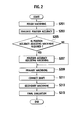
- Fig. 2 shows a flow from rough machining of the plate to a final evaluation stage.
- an unprocessed plate is roughly machined (step S201), position accuracy is evaluated (step S203), and it is determined whether eccentric machining is required (step S205).
- the eccentric machining is performed (step 5207), and then primary machining is performed (step S209) .
- the eccentric machining is omitted and the primary machining is performed (step S209) .
- step S211 ashaftisconnected to the primary-machined plate
- secondary machining is performed (step S213), and then, final evaluation is performed (step S215) .
- step S203 position accuracy evaluation (step S203) and determination whether the eccentric machining is required (step 5205) in the embodiment are performed between the rough machining of the plate (step S201) and the eccentric machining (step S207). It is determined whether the eccentric machining is required based on the position accuracy evaluation (step S203) (step S205).
- a first perimeter heater element, asecondperimeterheaterelement, ..., andaneighthperimeter heater element are embedded in the plate from the center of the plate toward an outer circumference thereof.
- a distance between the outer circumference of the plate and the outermost heater element (the eighth perimeter heater element) is measured at a plurality of points
- a distance between the outermost heater element and the fifth perimeter heater element is measured at a plurality of points.
- Fig. 3 is a flowchart showing the flow of the position accuracy evaluation. As shown in Fig. 3, the outer circumstance of the disk-shaped first material is substantially evenly divided into n, and a first position to an n-th position is measured (step S301).
- the disk-shaped first material is a ceramic plate, and the outer circumstance of the plate is divided into twelve, and the first position to the twelfth position is measured.
- the (n+1)th position which is an intersection of the first radius and a circular arc of the first circle, the first radius connecting the center of the disk-shaped first material and the first position, to the 2n-th position, which is an intersection of the n-th radius and the circular arc of the first circle, the n-th radius connecting the center of the disk-shaped first material and the n-th position, is measured next (step S303).
- the first perimeter heater element, the second perimeter heater element, ..., and the eighth perimeter heater element are formed in the ceramic plate.
- the first perimeter heater element is the heater element closest to the center of the plate
- the eighth perimeter heater element is the heater element closest to the outer circumference of the plate.
- a radius connecting the center of the plate and the first position on the outer circumference of the plate is the first radius
- intersection of the first radius and the eighth perimeter heater element is the thirteen-th position
- the (2n+1)th position, which is an intersection of the first radius and the circular arc of the secondcircle, to the 3n-thposition, which is an intersection of the n-th radius and the circular arc of the second circle, is measured (step 5305).
- the second circle is the fifth perimeter heater element.
- intersection of the first radius and the fifth perimeter heater element is the twenty-fifth position
- the first vector starting from the (n+1) thposition and ending at the first position to the n-th vector starting from the 2n-th position and ending at the n-th position is calculated (step S307) .
- a vector starting from the thirteen-th position and ending at the first position is the first vector
- the (n+1)th vector starting from the (2n+1)th position and ending at the (n+1)th position to the 2n-th vector starting from the 3n-th position and ending at the 2n-th position is calculated, respectively (step S309).
- a vector starting from the twenty-fifth position and ending at the thirteen-th position is the thirteen-th vector
- the first vector to the n-th vector is then added to calculate a first combined vector (step S311).
- all of the first vector, the second vector, the third vector, ..., and the twelfth vector are added to calculate the first combined vector.
- the (n+1)th vector to the 2n-th vector is added to calculate a second combined vector (step S313).
- all of the thirteen-th vector, the fourteen-thvector, the fifteen-thvector, ..., and the twenty-fourth vector are added to calculate the second combined vector.
- the second material position accuracy of the first circle and the second circle with respect to the outer circumference of the first material is evaluated based on the third combined vector obtained by adding the first and the second combined vectors (step 5315) .
- a mark is respectively displayed at the designed positions.
- the outer circumference of the first material, the circular arc of the first circle of the second material, or the circular arc of the second circle of the second material closest to the mark is designated as an actually measured position.
- marks are displayed at positions obtained by dividing the circular arc of a circle having a designed radius into 12, and the outer circumference closest to the marks is designated as the actually measured position.
- the ceramic plate has a dimension as designed, all the marks relating to the positions on the outer circumference should be displayed on the outer circumference of the plate photographed by the X-ray camera. Due to various reasons, however, all the marks are not always displayed on the outer circumference.
- the heaters are embedded at positions as designed, all the marks relating to the positions of the eighth perimeter heater element should be displayed on the eighth perimeter heater element photographed by the X-ray camera. Due to various reasons, however, all the marks are not always displayed on the eighth perimeter heater element. The same applies to the fifth perimeter heater element.
- Design value An example of a method for calculating the designed position (hereinafter, appropriately referred to as "design value") will be explained with reference to Figs. 4 and 5.
- Design value An example of a state in which the actually measured position deviates from the designed position is shown in Fig. 6A,6B.
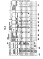
- Fig. 4 shows an example of basic information for calculating the designed position.
- an article name of the measurement object is input in an column 401, a number for a measurement object shape in an column 402, a score in outer circumference measurement information in an column 403, an offset angle in the outer circumference measurement information in an column 404, a hole diameter for PCD in an column 405, whether the coordinate system is an XY coordinate system or R ⁇ coordinate system is input in an column 406, and in the case of the R ⁇ coordinate system, radius R, or in the case of the XY coordinate system, X coordinate value is input in an column 407, in the case of the R ⁇ coordinate system, angle ⁇ , or in the case of the XY coordinate system, Y coordinate value is input in an column 408, a diameter when the object shape is the outer circumference or PCD is input in an column 409, a coordinate number in an column 410, and coordinate numbers of two points, a distance of which is to be measured, are input in an column 411, respectively.
- obj ect shape number "1" indicates that the obj ect shape is "point”
- object shape number "2" indicates that the object shape is "hole (three point measurement)”
- object shape number "3” indicates that the object shape is “outer circumference (n-point measurement)”
- object shape number "4" indicates that the object shape is "PCD measurement”.
- object shape: name corresponding to the coordinate number input in the column 411 is "hole” or “outer circumference”
- a distance between the hole or the outer circumference and the “center” is measured.
- the “PCD” in the object shape is a pitch circle diameter, and a diameter of a circle connecting central positions of lift pin holes.
- the “measurement angle” in the outer circumference measurement information is an angle between radial lines connecting the respective measurement points and the center, and "hole diameter” for PCD is a diameter of the lift pin hole.
- Fig. 5 shows one example of designed positions.
- Designed measurement positions (design values) as shown in Fig. 5 are calculated based on the coordinate information shown in Fig. 4. In the example shown in Fig. 5, the design value is expressed by radius r and angle ⁇ .
- Fig. 6A,6B shows an example of a designed heater position (hereinafter, referredtoas "heaterelementposition") andanactual heater element position.
- a heater position hereinafter, referredtoas "heaterelementposition”
- an image 601 of a heater element photographed by using the X-ray camera 101 is displayed on a display screen of the device 105.
- Fig. 6B is an enlarged view of the central part of Fig. 6A.
- a cursor 603 is displayed at the predetermined designed heater element position in the image of the photographed heater element.
- the designed heater element position indicated by the cursor 603 may displace from the actual heater element position photographed by the X-ray camera.
- the cursor 603 is moved onto the heater element displayed on the display device, by using a pointing device such as a mouse 106.
- the position of the cursor 603 at the time of occurrence of such an event is fetched in the storage unit of the PC 104 as the actual heater element position, by clicking a button on the mouse 106, or pressing an "Enter” key on the keyboard 11.
- the confirming process of the actual heater element position is repeated for the preset number of coordinates.
- the confirming process of the actual heater element position coil position may be automated. For example, a difference between the position according to design information and the actual position can be automatically fetched, by using a heater element position determination image processing function.
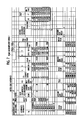
- Fig. 7 shows a distance and the like between the actual heater element position (measurement result) and a measurement position calculated from the measurement result.
- the X coordinate value or the radius r, and the Y coordinate value or the angle ⁇ obtained from the measurement result are displayed in a display column 703.
- a hole diameter, a diameter of the outer circumference, and a PCD diameter are displayed in a display column 705.
- the "hole diameter” is a diameter of the lift pin hole
- the "diameter of the outer circumference” is a diameter in the outermost portion of the heater element
- the "PCD diameter” is a pitch circle diameter connecting central positions of the lift pin holes.
- a difference in the X coordinate value between two points, a difference in the Y coordinate value between two points, and a distance between two points are displayed in a display column 707.
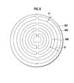
- a distance between the outer circumference of the plate and the outermost heater element, and a distance between the outermost heater element and the fifth perimeter heater element are shown in Fig. 8.
- the distance between the outer circumference of the plate and the outermost heater element stands for a distance d1 between the outer circumference 801 of the plate and the outermost heater element 803.
- the distance between the outermost heater element and the fifth perimeter heater element stands for a distance d2 between the outermost heater element 803 and the fifth perimeter heater element 805.
- the distances d1 and d2 are calculated based on the actual measurement values.
- Fig. 9 shows one example of a vector or a combined vector calculated from the actual measurement positions. Position accuracy analysis of the heater element is explained with reference to Fig. 9.
- a position at an angle of 15 degrees on the outer circumference of the plate is designated as a first position
- a position at an angle of 45 degrees is designated as a second position
- apositionat an angle of 75 degrees is designated as a third position
- a position at an angle of 345 degrees is designated as a twelfth position.
- Graph 901 indicates the content of Table 1 with regard to article name: heater sample A.
- a vector 903 starting from the central point in the graph 901 is the first vector starting from the thirteen-th position on the outermost heater element and ending at the first position on the outer circumference of the plate;
- a vector 916 obtained by combining vectors 903 to 914 corresponds to the first combined vector.
- the vector 916 has an angle ⁇ of 25 degrees and a length of 10.2 [mm].
- a graph 920 indicates the content of Table 2 with regard to article name: heater sample A.
- a vector 923 starting from the central point in the graph 920 is the thirteen-thvector starting from the twenty-fifthposition on the fifth perimeter heater element and ending at the thirteen-th position on the outermost heater element;
- a vector 936 obtained by combining vectors 923 to 934 corresponds to the second combined vector.
- the vector 936 has an angle ⁇ of 251 degrees and a length of 5.7 [mm].
- the third combined vector obtained by combining the vector 916 and the vector 936 has an angle ⁇ of 351 degrees and a length of 7.4 [mm].
- a graph 940 indicates the content of Table 3 with regard to article name: heater sample B.
- a vector 943 starting from the central point in the graph 940 is the first vector starting from the thirteen-th position on the outermost heater element and ending at the first position on the outer circumference of the plate;
- a vector 956 obtained by combining vectors 943 to 954 corresponds to the first combined vector.
- the vector 956 has an angle ⁇ of 291 degrees and a length of 9.1 [mm] .
- a graph 960 indicates the content of Table 4 with regard to article name: heater sample B.
- a vector 963 starting from the central point in the graph 960 is the thirteen-thvector starting from the twenty-fifthposition on the fifth perimeter heater element and ending at the thirteen-th position on the outermost heater element;
- a vector 976 obtained by combining vectors 963 to 974 corresponds to the second combined vector.
- the vector 976 has an angle ⁇ of 259 degrees and a length of 2.6 [mm].
- the third combined vector obtained by combining the vector 916 and the vector 936 has an angle ⁇ of 284 degrees and a length of 11.4 [mm].
- Fig. 10 shows a result of a conventional method for evaluating the temperature distribution using an infrared thermometer, by energizing the heater elements to heat the entire plate with respect to an article name: HC46302-00089, for which various vectors are shown in graphs 940 and 960 in Fig. 9.
- a radial range is 4.5 to 7.5°C
- the maximum value of a temperature difference on the same circumference is 4.8°C
- the maximum value of a temperature difference on the plate is 9.0°C.
- a vector 1001 has an angle 8 of 280 degrees and a length of 1.1 [mm].
- the radial range stands for the maximum value when a plurality of temperature differences are obtained on the same radial.
- a method for obtaining the angle and the length of the vector 1001 is such that an angle for changing the obtained temperature distribution to symmetrical distribution is obtained by multivariate analysis based on the obtained temperature distribution.
- the length the maximum temperature difference on the same radial on the outer circumference of the obtained temperature distribution map is first obtained, and an eccentricity required for modifying a 1°C of temperature difference stored in a database is multiplied to the maximum temperature difference, giving the length.
- the third combined vector obtained by the method according to the embodiment has the angle ⁇ of 284 degrees and the length of 11.4 [mm]. Since an eccentricity conversion rate of the combined vector value is 10%, the eccentricity after conversion becomes 1.14 [mm].
- the vector 1001 obtained by the conventional method has the angle ⁇ of 280 degrees and the length of 1.1 [mm]. That is, an equivalent result to that obtained by the conventional method can be obtained by the method according to the embodiment with regard to the eccentricity and the eccentric direction.
- the eccentricity and the eccentric direction with the accuracy equal to the conventional method can be obtained by the method according to the embodiment.
- the method according to the embodiment does not require energizing the heater elements to heat up the entire plate. Accordingly, there is an effect that the method according to the embodiment can perform process to get the eccentricity and the eccentric direction in a shorter period of time than that required in the conventional method.
Landscapes
- Length Measuring Devices With Unspecified Measuring Means (AREA)
- Length Measuring Devices By Optical Means (AREA)
- Image Processing (AREA)
- Image Analysis (AREA)
- Surface Heating Bodies (AREA)
- Resistance Heating (AREA)
Abstract
Description
- This application is based upon and claims the benefit of priority from a
Japanese Patent ApplicationNo. TOKUGAN 2 005-077929, filed on March 17, 2005 - The present invention relates to a method and an apparatus for evaluating position accuracy indicating, when members made of a second material are arranged within a disk-shaped first material so as to form a first circle of the second material having a radius of a first length and a second circle of the second material having a radius of a second length, deviation amounts of the actual first circle and the second circle from designed positions.
- There is conventionally known, as disclosed in
Japanese Patent Application Laid-Open No. 2004-079440 - However, according to the above-mentioned technique, it is necessary to attach an energizing electrode to the heaters, and energize the heaters for a predetermined period to heat the entire plate, before measuring the temperature distribution map. Therefore, there is a problem in that several tens of minutes are required until the temperature distribution map can be measured. As the plate becomes larger, the time required for energizing the heaters to heat the entire plate becomes longer.
- It is therefore an object of the present invention to provide a technique for evaluating the position accuracy of heaters with respect to the plate, without executing a process for energizing the heaters to heat the plate.
- According to a first aspect of the present invention, there is provided a method for evaluating position accuracy indicating, when members made of a second material are arranged within a disk-shaped first material so as to form a first circle of the second material having a radius of a first length and a second circle of the second material having a radius of a second length, deviation amounts of the first circle and the second circle from designed positions, comprising steps of: (1) substantially equally dividing an outer circumference of the disk-shaped first material into n and measuring a first position to an n-th position; (2) measuring an (n+1)th position, which is an intersection of a first radius connecting the center of the disk-shaped first material and the first position and a circular arc of the first circle, to a 2n-th position, which is an intersection of an n-th radius connecting the center of the disk-shaped first material and the n-th position and the circular arc of the first circle; (3) measuring a (2n+1)th position, which is an intersection of the first radius and a circular arc of the second circle, to a 3n-thposition, which is an intersection of the n-th radius and the circular arc of the second circle; (4) calculating a first vector starting from the (n+1)th position and ending at the first position to an n-th vector starting from the 2n-th position and ending at the n-th position; (5) calculating an (n+1)th vector starting from the (2n+1)th position and ending at the (n+1)th position to a 2n-th vector starting from the 3n-th position and ending at the 2n-th position; (6) calculating a first combined vector by adding the first to the n-th vectors; (7) calculating a second combined vector by adding the (n+1)th to the 2n-th vectors; and (8) evaluating the position accuracy of the first and the second circles with respect to the outer circumference of the disk-shaped first material, based on a third combined vector obtained by adding the first combined vector and the second combined vector, wherein "n" is a natural number of four or more.
- For the disk-shaped first material, nitride ceramics such as silicon nitride, aluminum nitride, boron nitride, and sialon, and an alumina-silicon carbide composite material are preferably used.
- For the second material, refractory metals such as tantalum, tungsten, molybdenum, platinum, rhenium, and hafnium, or alloys thereof are preferably used. Carbon, TiN, and TiC can be used as a conductive material other than the metal.
- "Members made of a second material are arranged ... so as to form a first circle having a radius of a first length" means that the members made of the second material need not be arranged so as to form a "complete" circle. As described later, a part of a circular arc may be missing. Further, "so as to form a circle ..." means that it is "intended" to form a circle. Generally, even if it is intended to arrange the members made of the second material within the disk-shaped first material so as to form a predetermined circle, it is not easy to arrange the members as designed. The present invention is to evaluate how much the members intended to be arranged as designed actuallydeviate from the designed positions.
- According to a second aspect of the present invention, the members made of the second material are arranged also between the center and the second circle so as to form a third, ..., and an m-th circle, the members made of the second material are arranged between the second circle and the first circle so as to form an (m+1)th, ..., and an (m+k) th circle, and differences in a radial length between respective adjacent circles are substantially equal.
- For example, if it is assumed that m=4, and k=4, the smallest circle is a third circle, a circle slightly larger than the third circle is a fourth circle, a circle slightly larger than the fourth circle is a fifth circle, a circle slightly larger than the fifth circle is a sixth circle, a circle slightly larger than the sixth circle is the second circle, a circle slightly larger than the second circle is a seventh circle, a circle slightly larger than the seventh circle is an eighth circle, and a circle slightly larger than the eighth circle is the first circle.
- When it is assumed that a difference in the radial length between adjacent two circles is Δr, then, the following relations are substantially established:
- (radial length of the third circle) + Δr≒ (radial length of the fourth circle);
- (radial length of the fourth circle) + Δr≒(radial length of the fifth circle);
- (radial length of the fifth circle) + Δr≒ (radial length of the sixth circle);
- (radial length of the sixth circle) + Δr≒(radial length of the second circle);
- (radial length of the second circle) + Δr≒(radial length of the seventh circle);
- (radial length of the seventh circle) + Δr≒(radial length of the eighth circle); and
- (radial length of the eighth circle) + Δr≒(radial length of the first circle).
- According to a third aspect of the present invention, the radius of the first circle is the longest among the radii of the first, the second, the third, ..., the m-th, the (m+1)th, ..., and the (m+k) th circles, and the radius of the second circle is substantially half the length of the radius of the first circle.
- For example, a relation of (radial length of the third circle) < (radial length of the fourth circle) < (radial length of the fifth circle) < (radial length of the sixth circle) < (radial length of the second circle) < (radial length of the seventh circle) < (radial length of the eighth circle) < (radial length of the first circle) is established, and a relation of (radial length of the second circle) ≒(radial length of the first circle)/2 is established.
- According to the first aspect of the present invention, the position accuracy of the first and the second circle made of the second material with respect to the outer circumference of the disk-shaped first material can be evaluated in a short period of time, based on the third combined vector.
- According to the second aspect of the present invention, the combined vector obtained by using the above method agrees well with an eccentric direction obtained from a temperature distribution map, and hence, the position accuracy of the first and the second circle made of the second material with respect to the outer circumference of the first disk-shaped material can be accurately evaluated.
- Exemplary embodiments of the invention will become more fully apparent from the following description and appended claims, taken in conjunction with the accompanying drawings. Understanding that these drawings depict only exemplary embodiments and are, therefore, not to be considered limiting of the invention' s scope, the exemplary embodiments of the invention will be described with additional specificity and detail through use of the accompanying drawings in which:
- Figs. 1A, 1B show a schematic configuration of a position accuracy evaluation apparatus, in which Fig. 1A is an overall block diagram of the position accuracy evaluation apparatus, and Fig. 1B is a plan view for explaining movement of an XY stage;
- Fig. 2 is a flowchart showing a flow from rough machining of a plate to a final evaluation stage;
- Fig. 3 is a flowchart showing a flow of a position accuracy evaluation;
- Fig. 4 shows an example of basic information for calculating designed positions;
- Fig. 5 shows an example of the designed positions;
- Fig. 6A, 6B show an example of a designed heater element position and an actual heater element position, in which Fig. 6A shows an image of a heater element photographed by an X-ray camera, and Fig. 6B is an enlarged view of a central part of Fig. 6A;
- Fig. 7 shows a distance and the like between the actual heater element position (measurement result) and a measurement position calculated from the measurement result;
- Fig. 8 shows a distance d1 between an outer circumference of the plate and an outermost heater element, and a distance d2 between the outermost heater element and a fifth perimeter heater element:
- Fig. 9 shows an example of a vector or a combined vector calculated from the actual measurement positions; and
- Fig. 10 shows a result of a conventional method for evaluating the temperature distribution using an infrared thermometer.
- Various embodiments of the invention are now described with reference to the Figures. The embodiments of the present invention, as generally described and illustrated in the Figures herein, could be arranged and designed in a wide variety of different configurations. Thus, the following more detailed description of several exemplary embodiments of the present invention, as represented in the Figures, is not intended to limit the scope of the invention, as claimed, but is merely representative of the embodiments of the invention.
- The word "exemplary" is used exclusively herein to mean "serving as an example, instance, or illustration." Any embodiment described herein as "exemplary" is not necessarily to be construed as preferred or advantageous over other embodiments. While the various aspects of the embodiments are presented in drawings, the drawings are not necessarily drawn to scale unless specifically indicated.
- Figs. 1A, 1B show a schematic configuration of a position accuracy evaluation apparatus. Fig. 1A is an overall block diagram of the position accuracy evaluation apparatus, and Fig. 1B is a plan view for explaining movement of an XY stage. As shown in Figs. 1A and 1B, a position
accuracy evaluation apparatus 100 includes anX-ray camera 101, anXY stage 102 movable in X and Y directions with a measurement object (sample) 103 placed thereon, and a personal computer (PC) 104 that controls theX-ray camera 101 and theXY stage 102. ThePC 104 includes adisplay device 105 such as a CRT or a liquid crystal display, apointing device 106 such as a mouse, a track pad, or a stick pointer, a character/numeric input unit 107 such as a keyboard, a hard disk drive (HDD) (not shown) and a central processing unit (CPU). The HDD is one example of a storage unit that can store measurement object positions of the sample and members therein, and the CPU is one example of a calculating unit that can calculate a vector starting from one of the measurement obj ect positions and ending at the other measurement obj ect position, and also calculate the sum of two or more vectors. - The position
accuracy evaluation apparatus 100 also includes an XY stage drive unit (not shown). Even if theX-ray camera 101 cannot observe theentire measurement object 103 by one shot, theentire measurement object 103 can be observed without exception by appropriately moving the XY stage in X and Y directions. For example, even if the observable range by theX-ray camera 101 by one shot is 200 mm in diameter, if theXY stage 102 can move 100 mm in X and Y directions, respectively, a photographable range is 400 mm by dividing photographing to five shots. - Photographing the entire
measurement obj ect 103 byaplurality of shots means that the range to be observed by theX-ray camera 101 by one shot becomes narrower as compared to photographing theentire measurement object 103 by one shot, which has a merit in that measurement errors decrease. - Fig. 2 shows a flow from rough machining of the plate to a final evaluation stage. As shown in Fig. 2, an unprocessed plate is roughly machined (step S201), position accuracy is evaluated (step S203), and it is determined whether eccentric machining is required (step S205). When the eccentric machining is required, the eccentric machining is performed (step 5207), and then primary machining is performed (step S209) . When the eccentric machining is not required, the eccentric machining is omitted and the primary machining is performed (step S209) . Thereafter, ashaftisconnected to the primary-machined plate (step S211), secondary machining is performed (step S213), and then, final evaluation is performed (step S215) .
- Thus, position accuracy evaluation (step S203) and determination whether the eccentric machining is required (step 5205) in the embodiment are performed between the rough machining of the plate (step S201) and the eccentric machining (step S207). It is determined whether the eccentric machining is required based on the position accuracy evaluation (step S203) (step S205).
- For example, it is assumed that a first perimeter heater element, asecondperimeterheaterelement, ..., andaneighthperimeter heater element are embedded in the plate from the center of the plate toward an outer circumference thereof. In this case, a distance between the outer circumference of the plate and the outermost heater element (the eighth perimeter heater element) is measured at a plurality of points, and a distance between the outermost heater element and the fifth perimeter heater element is measured at a plurality of points. Based on measurement data, the relative position of the outermost heater element with respect to the outer circumference of the plate, and the relative position of the fifth perimeter heater element with respect to the outermost heater element are calculated.
- Fig. 3 is a flowchart showing the flow of the position accuracy evaluation. As shown in Fig. 3, the outer circumstance of the disk-shaped first material is substantially evenly divided into n, and a first position to an n-th position is measured (step S301).
- In the embodiment, the disk-shaped first material is a ceramic plate, and the outer circumstance of the plate is divided into twelve, and the first position to the twelfth position is measured.
- The (n+1)th position, which is an intersection of the first radius and a circular arc of the first circle, the first radius connecting the center of the disk-shaped first material and the first position, to the 2n-th position, which is an intersection of the n-th radius and the circular arc of the first circle, the n-th radius connecting the center of the disk-shaped first material and the n-th position, is measured next (step S303).
- In the embodiment, the first perimeter heater element, the second perimeter heater element, ..., and the eighth perimeter heater element are formed in the ceramic plate. The first perimeter heater element is the heater element closest to the center of the plate, and the eighth perimeter heater element is the heater element closest to the outer circumference of the plate.
- A radius connecting the center of the plate and the first position on the outer circumference of the plate is the first radius;
- a radius connecting the center of the plate and the second position on the outer circumference of the plate is the second radius;
- a radius connecting the center of the plate and the third position on the outer circumference of the plate is the third radius; ...; and
- a radius connecting the center of the plate and the twelfth position on the outer circumference of the plate is a twelfth radius, that is, n=12.
- An intersection of the first radius and the eighth perimeter heater element is the thirteen-th position;
- an intersection of the second radius and the eighth perimeter heater element is the fourteen-th position;
- an intersection of the third radius and the eighth perimeter heater element is the fifteen-th position; ...; and
- an intersection of the twelfth radius and the eighth perimeter heater element is the twenty-fourth position.
- The (2n+1)th position, which is an intersection of the first radius and the circular arc of the secondcircle, to the 3n-thposition, which is an intersection of the n-th radius and the circular arc of the second circle, is measured (step 5305).
- In the embodiment, the second circle is the fifth perimeter heater element.
- An intersection of the first radius and the fifth perimeter heater element is the twenty-fifth position;
- an intersection of the second radius and the fifth perimeter heater element is the twenty-sixth position;
- an intersection of the third radius and the fifth perimeter heater element is the twenty-seven-th position; ...; and
- an intersection of the twelfth radius and the fifth perimeter heater element is the thirty-sixth position.
- The first vector starting from the (n+1) thposition and ending at the first position to the n-th vector starting from the 2n-th position and ending at the n-th position is calculated (step S307) .
- In the embodiment, a vector starting from the thirteen-th position and ending at the first position is the first vector;
- a vector starting from the fourteen-th position and ending at the second position is the second vector;
- a vector starting from the fifteen-th position and ending at the third position is the third vector; ...; and
- a vector starting from the twenty-fourth position and ending at the twelfth position is the twelfth vector.
- The (n+1)th vector starting from the (2n+1)th position and ending at the (n+1)th position to the 2n-th vector starting from the 3n-th position and ending at the 2n-th position is calculated, respectively (step S309).
- In the embodiment, a vector starting from the twenty-fifth position and ending at the thirteen-th position is the thirteen-th vector;
- a vector starting from the twenty-sixth position and ending at the fourteen-th position is the fourteen-th vector;
- avectorstarting from the twenty-seven-thposition and ending at the fifteen-th position is the fifteen-th vector; ...; and
- a vector starting from the thirty-sixth position and ending at the twenty-fourth position is the twenty-fourth vector.
- The first vector to the n-th vector is then added to calculate a first combined vector (step S311).
- In the embodiment, all of the first vector, the second vector, the third vector, ..., and the twelfth vector are added to calculate the first combined vector.
- The (n+1)th vector to the 2n-th vector is added to calculate a second combined vector (step S313).
- In the embodiment, all of the thirteen-th vector, the fourteen-thvector, the fifteen-thvector, ..., and the twenty-fourth vector are added to calculate the second combined vector.
- Lastly, the second material position accuracy of the first circle and the second circle with respect to the outer circumference of the first material is evaluated based on the third combined vector obtained by adding the first and the second combined vectors (step 5315) .
- When respective positions are to be measured, a mark is respectively displayed at the designed positions. The outer circumference of the first material, the circular arc of the first circle of the second material, or the circular arc of the second circle of the second material closest to the mark is designated as an actually measured position.
- In an example in which the outer circumference is divided into 12, marks are displayed at positions obtained by dividing the circular arc of a circle having a designed radius into 12, and the outer circumference closest to the marks is designated as the actually measured position. If the ceramic plate has a dimension as designed, all the marks relating to the positions on the outer circumference should be displayed on the outer circumference of the plate photographed by the X-ray camera. Due to various reasons, however, all the marks are not always displayed on the outer circumference. Likewise, if the heaters are embedded at positions as designed, all the marks relating to the positions of the eighth perimeter heater element should be displayed on the eighth perimeter heater element photographed by the X-ray camera. Due to various reasons, however, all the marks are not always displayed on the eighth perimeter heater element. The same applies to the fifth perimeter heater element.
- An example of a method for calculating the designed position (hereinafter, appropriately referred to as "design value") will be explained with reference to Figs. 4 and 5. An example of a state in which the actually measured position deviates from the designed position is shown in Fig. 6A,6B.
- Fig. 4 shows an example of basic information for calculating the designed position. As shown in Fig. 4, an article name of the measurement object is input in an
column 401, a number for a measurement object shape in ancolumn 402, a score in outer circumference measurement information in ancolumn 403, an offset angle in the outer circumference measurement information in ancolumn 404, a hole diameter for PCD in ancolumn 405, whether the coordinate system is an XY coordinate system or Rθ coordinate system is input in ancolumn 406, and in the case of the Rθ coordinate system, radius R, or in the case of the XY coordinate system, X coordinate value is input in ancolumn 407, in the case of the Rθ coordinate system, angle θ, or in the case of the XY coordinate system, Y coordinate value is input in ancolumn 408, a diameter when the object shape is the outer circumference or PCD is input in ancolumn 409, a coordinate number in ancolumn 410, and coordinate numbers of two points, a distance of which is to be measured, are input in ancolumn 411, respectively. - For example, obj ect shape number "1" indicates that the obj ect shape is "point", object shape number "2" indicates that the object shape is "hole (three point measurement)", object shape number "3" indicates that the object shape is "outer circumference (n-point measurement)", and object shape number "4" indicates that the object shape is "PCD measurement".
- When "object shape: name" corresponding to the coordinate number input in the
column 411 is "hole" or "outer circumference", a distance between the hole or the outer circumference and the "center" is measured. The "PCD" in the object shape is a pitch circle diameter, and a diameter of a circle connecting central positions of lift pin holes. The "measurement angle" in the outer circumference measurement information is an angle between radial lines connecting the respective measurement points and the center, and "hole diameter" for PCD is a diameter of the lift pin hole. - Fig. 5 shows one example of designed positions. Designed measurement positions (design values) as shown in Fig. 5 are calculated based on the coordinate information shown in Fig. 4. In the example shown in Fig. 5, the design value is expressed by radius r and angle θ.
- "
Point 2,object number 1" in Fig. 5 corresponds to coordinate information No. 1 in Fig. 4. As shown in Fig. 4, in coordinate information No. 1, as the Rθ coordinate system, radius r = 123 [mm] and angle θ = 180 degrees are given initially. Therefore, the design value for "Point 2,object number 1" indicates radius r = 123.00 [mm] and angle θ = 180.00 degrees. - "
Point 3,object number 2" to "Point 11,object number 2" in Fig. 5 correspond to coordinate information No. 2 in Fig. 4. As shown in Fig. 4, in coordinate information No. 2, offset angle = 30 degrees and diameter = 318 [mm] are given as the outer circumference measurement information. Therefore, the design value for "Point 3,object number 2" indicates radius r = 159.00 [mm] and angle θ = 30.00 degrees. Further, in the coordinate informationNo. 2, since score = 9 is given as the outer circumference measurement information, the interval between "Point 3,object number 2" and "Point 4,object number 2" is 360/9 = 40 degrees. Accordingly, the design value for "Point 4,obj ect number 2" indicates radius r = 159.00 [mm] and angle θ = 70.00 degrees. - Likewise, the design value for "
Point 5,object number 2" in Fig. 5 indicates radius r = 159.00 [mm] and angle θ = 110.00 degrees; - "
Point 6,object number 2" indicates radius r = 159.00 [mm] and angle θ = 150.00 degrees; - "
Point 7,object number 2" indicates radius r = 159.00 [mm] and angle θ = 190.00 degrees; - "
Point 8,object number 2" indicates radius r = 159.00 [mm] and angle θ = 230.00 degrees; - "
Point 9,object number 2" indicates radius r = 159.00 [mm] and angle θ = 270.00 degrees; - "
Point 10,object number 2" indicates radius r = 159.00 [mm] and angle θ = 310.00 degrees; and - "
Point 11,object number 2" indicates radius r = 159.00 [mm] and angle θ = 350.00 degrees. - "
Point 12,obj ect number 3" in Fig. 5 corresponds to coordinate information No. 3 in Fig. 4. As shown in Fig. 4, in coordinate information No. 3, X coordinate value = 11.2 [mm] and Y coordinate value = 8 [mm] are given as the XY coordinate system. Based on these values, radius r = 13.76 [mm] and angle θ = 35.54 degrees are calculated as the design value for "Point 12,object number 3" in Fig. 5. - Likewise, based on X coordinate value = -4.8 [mm] and Y coordinate value = 8 [mm] in coordinate information No. 4, radius r = 9.33 [mm] and angle θ = 120.96 degrees are calculated as the design value for "
Point 13,object number 4" in Fig. 5. - Based on X coordinate value = -4 . 8 [mm] and Y coordinate value = -8 [mm] in coordinate information No. 5, radius r = 9.33 [mm] and angle θ = 239.04 degrees are calculated as the design value for "
Point 14,object number 5" in Fig. 5. - Based on X coordinate value = 11. 2 [mm] and Y coordinate value = -8 [mm] in coordinate information No. 6, radius r = 13.76 [mm] and angle θ = 324.46 degrees are calculated as the design value for "
Point 15,object number 6" in Fig. 5. In this manner, designed heater positions are determined for each article. - Fig. 6A,6B shows an example of a designed heater position (hereinafter, referredtoas "heaterelementposition") andanactual heater element position. As shown in Fig. 6A, an
image 601 of a heater element photographed by using theX-ray camera 101 is displayed on a display screen of thedevice 105. - Fig. 6B is an enlarged view of the central part of Fig. 6A. As shown in Fig. 6B, a
cursor 603 is displayed at the predetermined designed heater element position in the image of the photographed heater element. As shown in Fig. 6B, the designed heater element position indicated by thecursor 603 may displace from the actual heater element position photographed by the X-ray camera. In this case, thecursor 603 is moved onto the heater element displayed on the display device, by using a pointing device such as amouse 106. Then the position of thecursor 603 at the time of occurrence of such an event is fetched in the storage unit of thePC 104 as the actual heater element position, by clicking a button on themouse 106, or pressing an "Enter" key on thekeyboard 11. The confirming process of the actual heater element position is repeated for the preset number of coordinates. - The confirming process of the actual heater element position coil position may be automated. For example, a difference between the position according to design information and the actual position can be automatically fetched, by using a heater element position determination image processing function.
- Fig. 7 shows a distance and the like between the actual heater element position (measurement result) and a measurement position calculated from the measurement result. As shown in Fig. 7, radius r and angle θ obtained from the measurement result are displayed in a
display column 701. Specifically, radius r = 147 [mm] and angle θ = 0 are displayed as a measurement result corresponding topoint 1, radius r = 123 [mm] and angle θ = 180.27 are displayed as a measurement result corresponding topoint 2, radius r = 158.2 [mm] and angle θ = 19.99 are displayed as a measurement result corresponding topoint 3, radius r = 158.29 [mm] and angle θ = 59.99 are displayed as a measurement result corresponding topoint 4, and radius r = 158.31 [mm] and angle θ = 99.99 are displayed as a measurement result corresponding topoint 5. - The X coordinate value or the radius r, and the Y coordinate value or the angle θ obtained from the measurement result are displayed in a display column 703. The first line in the display column 703 relates to a reference point at the angle θ, and indicates that the reference point at the angle θ indicates radius R = 147.00 mm, and angle θ = 0.0 degree.
- The second line in the display column 703 relates to a point of coordinate informationNo. 1, and the measurement result indicates radius r = 123.00 mm, and angle θ = 180.27 degrees.
- The third line in the display column 703 relates to the outer circumference of coordinate information No. 2, and the measurement result indicates radius R = 0.20 mm, and angle θ deviates by 237.83 degrees.
- The fourth line in the display column 703 relates to a point of coordinate informationNo. 3, and the measurement result indicates X coordinate value = 10.94 [mm] and Y coordinate value = 7.81 [mm] .
- The fifth line in the display column 703 relates to a point of coordinate information No. 4, and the measurement result indicates X coordinate value = 11.51 [mm] and Y coordinate value = -8.23 [mm].
- The sixth line in the display column 703 relates to a point of coordinate informationNo. 5, and the measurement result indicates X coordinate value = -4.95 [mm] and Y coordinate value = -8.25 [mm].
- The seventh line in the display column 703 relates to a point of coordinate information No. 6, and the measurement result indicates X coordinate value = -4.52 [mm] and Y coordinate value = 7.54 [mm].
- The eighth line in the display column 703 relates to a point of coordinate informationNo. 7, and the measurement result indicates X coordinate value = 0.00 mm and Y coordinate value = 0.00 mm.
- A hole diameter, a diameter of the outer circumference, and a PCD diameter are displayed in a display column 705. The "hole diameter" is a diameter of the lift pin hole, the "diameter of the outer circumference" is a diameter in the outermost portion of the heater element, and the "PCD diameter" is a pitch circle diameter connecting central positions of the lift pin holes.
- A difference in the X coordinate value between two points, a difference in the Y coordinate value between two points, and a distance between two points are displayed in a
display column 707. The first line in thedisplay column 707 relates to point 3 andpoint 4, indicating X coordinate value ofpoint 3 + 0.57 [mm] = X coordinate value ofpoint 4, Y coordinate value of point 3 - 16.04 [mm] = Y coordinate value ofpoint 4, and distance betweenpoint 3 andpoint 4 = 16.05. - The second line in the
display column 707 relates to point 4 andpoint 5, indicating X coordinate value of point 4 - 16.46 [mm] = X coordinate value ofpoint 5, Y coordinate value of point 4 - 0.02 [mm] = Y coordinate value ofpoint 5, and distance betweenpoint 4 andpoint 5 = 16.46. - The third line in the
display column 707 relates to point 5 andpoint 6, indicating X coordinate value ofpoint 5 + 0.43 [mm] = X coordinate value ofpoint 6, Y coordinate value ofpoint 5 + 15.79 [mm] = Y coordinate value ofpoint 6, and distance betweenpoint 5 andpoint 6 = 15.80. - A distance between the outer circumference of the plate and the outermost heater element, and a distance between the outermost heater element and the fifth perimeter heater element are shown in Fig. 8. As shown in Fig. 8, the distance between the outer circumference of the plate and the outermost heater element stands for a distance d1 between the
outer circumference 801 of the plate and theoutermost heater element 803. The distance between the outermost heater element and the fifth perimeter heater element stands for a distance d2 between theoutermost heater element 803 and the fifthperimeter heater element 805. The distances d1 and d2 are calculated based on the actual measurement values. - Fig. 9 shows one example of a vector or a combined vector calculated from the actual measurement positions. Position accuracy analysis of the heater element is explained with reference to Fig. 9. In the example shown in Fig. 9, a position at an angle of 15 degrees on the outer circumference of the plate is designated as a first position, a position at an angle of 45 degrees is designated as a second position, apositionat an angle of 75 degrees is designated as a third position, ..., and a position at an angle of 345 degrees is designated as a twelfth position. Further, the distance d1 between the outer circumference of the plate and the outermost heater element on the outermost heater element is plotted respectively for the angle θ = 15 degrees, 45 degrees, 75 degrees, 105 degrees, 135 degrees, 165 degrees, 195 degrees, 225 degrees, 255 degrees, 285 degrees, 315 degrees, and 345 degrees.
-
Graph 901 indicates the content of Table 1 with regard to article name: heater sample A.TABLE 1 ANGLE θ [DEGREES] POSITION NUMBER ON OUTER CIRCUMFERENCE OF PLATE POSITION NUMBER ON OUTERMOST HEATED ELEMENT DISTANCE d1 [mm] 15 1 13 7.0 45 2 14 7.0 75 3 15 6.1 105 4 16 5.4 135 5 17 4.2 165 6 18 4.0 195 7 19 3.2 225 8 20 3.0 255 9 21 4.1 285 10 22 5.1 315 11 23 6.2 345 12 24 6.0 - A
vector 903 starting from the central point in thegraph 901 is the first vector starting from the thirteen-th position on the outermost heater element and ending at the first position on the outer circumference of the plate; - a
vector 904 is the secondvector starting from the fourteen-th position and ending at the second position; - a
vector 905 is the third vector starting from the fifteen-th position and ending at the third position; and - a
vector 914 is the twelfth vector starting from the twenty-fourth position and ending at the twelfth position. - A
vector 916 obtained by combiningvectors 903 to 914 corresponds to the first combined vector. Thevector 916 has an angle θ of 25 degrees and a length of 10.2 [mm]. - A
graph 920 indicates the content of Table 2 with regard to article name: heater sample A.TABLE 2 ANGLE θ [DEGREES] POSITION NUMBER ON OUTERMOST HEATER ELEMENT POSITION NUMBER ON FIFTH PERIMETER HEATER ELEMENT DISTANCE d2 [mm] 15 13 25 39.6 45 14 26 38.5 75 15 27 39.1 105 16 28 39.0 135 17 29 38.9 165 18 30 38.6 195 19 31 39.9 225 20 32 40.0 255 21 33 40.0 285 22 34 39.5 315 23 35 40.0 345 24 36 38.5 - A
vector 923 starting from the central point in thegraph 920 is the thirteen-thvector starting from the twenty-fifthposition on the fifth perimeter heater element and ending at the thirteen-th position on the outermost heater element; - a
vector 924 is the fourteen-th vector starting from the twenty-sixth position and ending at the fourteen-th position; - a
vector 925 is the fifteen-th vector starting from the twenty-seven-th position and ending at the fifteen-th position; ... ; and - a
vector 934 is the twenty-fourth vector starting from the thirty-sixth position and ending at the twenty-fourth position. - A
vector 936 obtained by combiningvectors 923 to 934 corresponds to the second combined vector. Thevector 936 has an angle θ of 251 degrees and a length of 5.7 [mm]. - The third combined vector obtained by combining the
vector 916 and thevector 936 has an angle θ of 351 degrees and a length of 7.4 [mm]. - A
graph 940 indicates the content of Table 3 with regard to article name: heater sample B.TABLE 3 ANGLE θ [DEGREES] POSITION NUMBER ON OUTER CIRCUMFERENCE OF PLATE POSITION NUMBER ON OUTERMOST HEATED ELEMENT DISTANCE d1 [mm] 15 1 13 5.6 45 2 14 4.4 75 3 15 4.0 105 4 16 4.1 135 5 17 3.9 165 6 18 4.7 195 7 19 4.9 225 8 20 6.0 255 9 21 6.1 285 10 22 7.1 315 11 23 6.6 345 12 24 6.3 - A
vector 943 starting from the central point in thegraph 940 is the first vector starting from the thirteen-th position on the outermost heater element and ending at the first position on the outer circumference of the plate; - a
vector 944 is the secondvector starting from the fourteen-th position and ending at the second position; - a
vector 945 is the third vector starting from the fifteen-th position and ending at the third position; ...; and - a
vector 954 is the twelfth vector starting from the twenty-fourth position and ending at the twelfth position. - A
vector 956 obtained by combiningvectors 943 to 954 corresponds to the first combined vector. Thevector 956 has an angle θ of 291 degrees and a length of 9.1 [mm] . - A
graph 960 indicates the content of Table 4 with regard to article name: heater sample B.TABLE 4 ANGLE θ [DEGREES] POSITION NUMBER ON OUTERMOST HEATER ELEMENT POSITION NUMBER ON FIFTH PERIMETER HEATER ELEMENT DISTANCE d2 [mm] 15 13 25 39.5 45 14 26 39.0 75 15 27 39.6 105 16 28 39.5 135 17 29 39.0 165 18 30 38.9 195 19 31 39.6 225 20 32 40.0 255 21 33 40.5 285 22 34 40.1 315 23 35 40.0 345 24 36 39.9 - A
vector 963 starting from the central point in thegraph 960 is the thirteen-thvector starting from the twenty-fifthposition on the fifth perimeter heater element and ending at the thirteen-th position on the outermost heater element; - a
vector 964 is the fourteen-th vector starting from the twenty-sixth position and ending at the fourteen-th position; - a
vector 965 is the fifteen-th vector starting from the twenty-seven-th position and ending at the fifteen-th position; ... ; and - a
vector 974 is the twenty-fourth vector starting from the thirty-sixth position and ending at the twenty-fourth position. - A
vector 976 obtained by combiningvectors 963 to 974 corresponds to the second combined vector. Thevector 976 has an angle θ of 259 degrees and a length of 2.6 [mm]. - The third combined vector obtained by combining the
vector 916 and thevector 936 has an angle θ of 284 degrees and a length of 11.4 [mm]. - On the other hand, Fig. 10 shows a result of a conventional method for evaluating the temperature distribution using an infrared thermometer, by energizing the heater elements to heat the entire plate with respect to an article name: HC46302-00089, for which various vectors are shown in
graphs - As shown in Fig. 10, a radial range is 4.5 to 7.5°C, the maximum value of a temperature difference on the same circumference is 4.8°C, and the maximum value of a temperature difference on the plate is 9.0°C. A vector 1001 has an
angle 8 of 280 degrees and a length of 1.1 [mm]. - The radial range stands for the maximum value when a plurality of temperature differences are obtained on the same radial. A method for obtaining the angle and the length of the vector 1001 is such that an angle for changing the obtained temperature distribution to symmetrical distribution is obtained by multivariate analysis based on the obtained temperature distribution. As for the length, the maximum temperature difference on the same radial on the outer circumference of the obtained temperature distribution map is first obtained, and an eccentricity required for modifying a 1°C of temperature difference stored in a database is multiplied to the maximum temperature difference, giving the length.
- The third combined vector obtained by the method according to the embodiment has the angle θ of 284 degrees and the length of 11.4 [mm]. Since an eccentricity conversion rate of the combined vector value is 10%, the eccentricity after conversion becomes 1.14 [mm].
- On the other hand, the vector 1001 obtained by the conventional method has the angle θ of 280 degrees and the length of 1.1 [mm]. That is, an equivalent result to that obtained by the conventional method can be obtained by the method according to the embodiment with regard to the eccentricity and the eccentric direction.
- Thus, the eccentricity and the eccentric direction with the accuracy equal to the conventional method can be obtained by the method according to the embodiment. The method according to the embodiment does not require energizing the heater elements to heat up the entire plate. Accordingly, there is an effect that the method according to the embodiment can perform process to get the eccentricity and the eccentric direction in a shorter period of time than that required in the conventional method.
Claims (4)
- A method for evaluating position accuracy indicating, when members made of a second material are arranged within a disk-shaped first material so as to form a first circle of the second material having a radius of a first length and a second circle of the second material having a radius of a second length, deviation amounts of the first circle and the second circle from designed positions, comprising steps of:substantially equally dividing an outer circumference of the disk-shaped first material into n and measuring a first position to an n-th position;measuring an (n+1)th position, which is an intersection of a first radius and a circular arc of the first circle, the first radius connecting the center of the disk-shaped first material and the first position, to a 2n-th position, which is an intersection of an n-th radius and the circular arc of the first circle, the n-th radius connecting the center of the disk-shaped first material and the n-th position;measuring a (2n+1)th position, which is an intersection of the first radius and a circular arc of the second circle, to a 3n-th position, which is an intersection of the n-th radius and the circular arc of the second circle;calculating a first vector starting from the (n+1)thposition and ending at the first position to an n-th vector starting from the 2n-th position and ending at the n-th position;calculating an (n+1)th vector starting from the (2n+1)th position and ending at the (n+1) thposition to a 2n-th vector starting from the 3n-th position and ending at the 2n-th position;calculating a first combined vector by adding the first to the n-th vectors;calculating a second combined vector by adding the (n+1) th to the 2n-th vectors; andevaluating the position accuracy of the first and the second circles with respect to the outer circumference of the disk-shaped first material, based on a third combined vector obtained by adding the first combined vector and the second combined vector, wherein "n" is a natural number of four or more.
- The method for evaluating position accuracy according to claim 1, wherein
the members made of the second material are also arranged between the first circle and the second circle, so as to form a third, ..., and an m-th circle,
the members made of the second material are also arranged between the second circle and the center of the disk-shaped first material, so as to form an (m+1)th, ..., and an (m+k) th circle, and
differences in a radial length between adjacent circles are substantially equal. - The method for evaluating position accuracy according to claim 2, wherein
the radius of the first circle is the longest among the radii of the first, the second, the third, ..., the m-th, the (m+1)th, ..., and the (m+k)th circles, and
the radius of the second circle is substantially half the length of the radius of the first circle. - A position accuracy evaluation apparatus (100) comprising:an XY stage (102);an XY stage drive unit that moves the XY stage (102) in an X or Y direction;a camera (101) that is arranged above the XY stage (102) and that can photograph an outer circumference of a sample (103) formed of a disk-shaped first material placed on the XY stage (102), and a first circle having a radius of a first length and a second circle having a radius of a second length, which are members made of a second material and are embedded in the sample (103);a storage unit (104) that can store measurement object positions of the sample (103) and the members;a calculation unit (104) that can calculate a vector starting from one of the measurement object positions and ending at the other measurement object position, and the sum of two or more vectors; anda controller (104) that controls the XY stage drive unit, the camera (101), the storage unit (104), and the calculation unit (104), whereinthe controller (104) controls such thatthe XY stage drive unit moves the XY stage (102) so that portions to be photographed of the sample (103) and the members are within a photographable range of the camera (101),the camera (101) measures:a first position to an n-thposition on the outer circumference of the disk-shaped first material, obtained by substantially equally dividing the outer circumference into n;an (n+1)thposition, which is an intersection of a first radius and a circular arc of the first circle, the first radius connecting the center of the disk-shaped first material and the first position, to a 2n-th position, which is an intersection of an n-th radius and the circular arc of the first circle, the n-th radius connecting the center of the disk-shaped first material and the n-th position; anda (2n+1)th position, which is an intersection of the first radius and a circular arc of the second circle, to a 3n-th position, which is an intersection of the n-th radius and the circular arc of the second circle,the storage unit (104) stores the first position to the 3n-th position, andthe calculation unit (104) calculates:a first vector starting from the (n+1) th position and ending at the first position to an n-th vector starting from the 2n-th position and ending at the n-th position;an (n+1)th vector starting from the (2n+1)th position and ending at the (n+1)th position to a 2n-th vector starting from the 3n-th position and ending at the 2n-th position;a first combined vector by adding the first to the n-thvectors;a second combined vector by adding the (n+1)th to the 2n-th vectors; anda third combined vector by adding the first combined vector and the second combined vector,so that the position accuracy of the first and the second circles of the second material with respect to the outer circumference of the disk-shaped first material is evaluated based on the third combined vector, wherein n is a natural number of four or more.
Applications Claiming Priority (1)
| Application Number | Priority Date | Filing Date | Title |
|---|---|---|---|
| JP2005077929A JP4728021B2 (en) | 2005-03-17 | 2005-03-17 | Heat uniformity evaluation method and heat uniformity evaluation apparatus |
Publications (2)
| Publication Number | Publication Date |
|---|---|
| EP1703777A1 true EP1703777A1 (en) | 2006-09-20 |
| EP1703777B1 EP1703777B1 (en) | 2007-11-21 |
Family
ID=36645689
Family Applications (1)
| Application Number | Title | Priority Date | Filing Date |
|---|---|---|---|
| EP06251440A Ceased EP1703777B1 (en) | 2005-03-17 | 2006-03-17 | Position accuracy evaluation method and apparatus |
Country Status (6)
| Country | Link |
|---|---|
| US (1) | US7948516B2 (en) |
| EP (1) | EP1703777B1 (en) |
| JP (1) | JP4728021B2 (en) |
| KR (1) | KR100733444B1 (en) |
| DE (1) | DE602006000249T2 (en) |
| TW (1) | TWI315161B (en) |
Citations (5)
| Publication number | Priority date | Publication date | Assignee | Title |
|---|---|---|---|---|
| US20020179592A1 (en) * | 2000-07-19 | 2002-12-05 | Yasuji Hiramatsu | Semiconductor manufacturing/testing ceramic heater, production method for the ceramic heater and production system for the ceramic heater |
| US20030047555A1 (en) * | 2001-08-28 | 2003-03-13 | Gyeong-Su Keum | Heater assembly for heating a wafer |
| US20040104211A1 (en) * | 2002-08-21 | 2004-06-03 | Ngk Insulators, Ltd. | Heater and method of manufacturing same |
| US20040182850A1 (en) * | 2003-02-17 | 2004-09-23 | E.G.O. Elektro-Geraetebau Gmbh | Heating device with two areas |
| US20050035111A1 (en) * | 2003-08-12 | 2005-02-17 | Goodsel Arthur J. | Structure and method to compensate for thermal edge loss in thin film heaters |
Family Cites Families (6)
| Publication number | Priority date | Publication date | Assignee | Title |
|---|---|---|---|---|
| JPS6267404A (en) * | 1985-09-20 | 1987-03-27 | Seiko Epson Corp | Optical roundness measuring device |
| JPH0510718A (en) * | 1991-07-05 | 1993-01-19 | Nippon Densan Corp | Concentricity degree measuring apparatus |
| JP2001091244A (en) * | 1999-09-24 | 2001-04-06 | Tokyo Seimitsu Co Ltd | Roundness measuring method and device |
| JP2002054917A (en) * | 2000-08-08 | 2002-02-20 | M H Center:Kk | Concentricity measuring method in concentricity measuring device |
| JP3754340B2 (en) * | 2001-10-15 | 2006-03-08 | 株式会社デンソーウェーブ | Position detection device |
| JP2004328096A (en) * | 2003-04-22 | 2004-11-18 | Sony Corp | Image processing apparatus and method, recording medium, and program |
-
2005
- 2005-03-17 JP JP2005077929A patent/JP4728021B2/en not_active Expired - Lifetime
-
2006
- 2006-03-10 KR KR1020060022555A patent/KR100733444B1/en not_active Expired - Fee Related
- 2006-03-15 US US11/375,812 patent/US7948516B2/en active Active
- 2006-03-15 TW TW095108701A patent/TWI315161B/en not_active IP Right Cessation
- 2006-03-17 DE DE602006000249T patent/DE602006000249T2/en not_active Expired - Lifetime
- 2006-03-17 EP EP06251440A patent/EP1703777B1/en not_active Ceased
Patent Citations (5)
| Publication number | Priority date | Publication date | Assignee | Title |
|---|---|---|---|---|
| US20020179592A1 (en) * | 2000-07-19 | 2002-12-05 | Yasuji Hiramatsu | Semiconductor manufacturing/testing ceramic heater, production method for the ceramic heater and production system for the ceramic heater |
| US20030047555A1 (en) * | 2001-08-28 | 2003-03-13 | Gyeong-Su Keum | Heater assembly for heating a wafer |
| US20040104211A1 (en) * | 2002-08-21 | 2004-06-03 | Ngk Insulators, Ltd. | Heater and method of manufacturing same |
| US20040182850A1 (en) * | 2003-02-17 | 2004-09-23 | E.G.O. Elektro-Geraetebau Gmbh | Heating device with two areas |
| US20050035111A1 (en) * | 2003-08-12 | 2005-02-17 | Goodsel Arthur J. | Structure and method to compensate for thermal edge loss in thin film heaters |
Also Published As
| Publication number | Publication date |
|---|---|
| EP1703777B1 (en) | 2007-11-21 |
| KR100733444B1 (en) | 2007-06-29 |
| JP4728021B2 (en) | 2011-07-20 |
| DE602006000249T2 (en) | 2008-10-02 |
| US20060207987A1 (en) | 2006-09-21 |
| TW200644707A (en) | 2006-12-16 |
| DE602006000249D1 (en) | 2008-01-03 |
| TWI315161B (en) | 2009-09-21 |
| KR20060101260A (en) | 2006-09-22 |
| US7948516B2 (en) | 2011-05-24 |
| JP2006258665A (en) | 2006-09-28 |
Similar Documents
| Publication | Publication Date | Title |
|---|---|---|
| EP1775077B1 (en) | Parallel kinematic machine, calibration method of parallel kinematic machine, and calibration program product | |
| US10267620B2 (en) | Optical three-dimensional coordinate measuring device and measurement method thereof | |
| US20080155846A1 (en) | Micrometer-based measuring system and method of using same | |
| JPS63182509A (en) | Method and device for calibrating coordinate measuring machine | |
| Cuesta et al. | A new concept of feature-based gauge for coordinate measuring arm evaluation | |
| Guo | Reviews on the machining and measurement of large components | |
| Grochalski et al. | Thermal sources of errors in surface texture imaging | |
| CN101566466A (en) | Profile analysis system and method | |
| CN113950650A (en) | Adjustment amount estimation device, adjustment amount estimation method, and adjustment amount estimation program | |
| EP1703777B1 (en) | Position accuracy evaluation method and apparatus | |
| CN109708607A (en) | Detection device, detection method and storage equipment | |
| Franczyk | Development and verification of a measuring stand for recording the physical phenomena during turning | |
| Li et al. | Structure design and optimization for a cutting force measurement tool with embedded nickel–chromium film sensor | |
| JP2022090123A (en) | Quotation system, quotation method, and quotation program | |
| JP2000161903A (en) | Structure measurement system | |
| JP5775741B2 (en) | Shape measuring method, processing method using the same, and shape measuring apparatus | |
| Tomlinson et al. | Enhanced dual confocal measurement system | |
| Özdemir et al. | Prediction of tool deflection using image processing in ball-end milling | |
| Furgiuele et al. | A full-field procedure for evaluating the elastic properties of advanced ceramics | |
| Gadelmawla | Development of a Computerized Multi-Measurement System for Fine Measurements. | |
| Huy et al. | Automated Vickers hardness system with closed-loop control for polishing pads for semiconductor production | |
| Zhao et al. | High-precision surface parallelism measurement using digital image correlation method | |
| Balwan et al. | Development and Validation of an Automated 50 KN Dead Weight Force Measurement System and Dissemination of Uncertainty of Measurement | |
| Niu et al. | A prediction model for surface topography in robotic flat-end milling considering tool vibration and redundant angles | |
| Schuetz | Making Better Height Gage Measurements |
Legal Events
| Date | Code | Title | Description |
|---|---|---|---|
| PUAI | Public reference made under article 153(3) epc to a published international application that has entered the european phase |
Free format text: ORIGINAL CODE: 0009012 |
|
| AK | Designated contracting states |
Kind code of ref document: A1 Designated state(s): AT BE BG CH CY CZ DE DK EE ES FI FR GB GR HU IE IS IT LI LT LU LV MC NL PL PT RO SE SI SK TR |
|
| AX | Request for extension of the european patent |
Extension state: AL BA HR MK YU |
|
| 17P | Request for examination filed |
Effective date: 20061013 |
|
| AKX | Designation fees paid |
Designated state(s): DE FR GB |
|
| GRAP | Despatch of communication of intention to grant a patent |
Free format text: ORIGINAL CODE: EPIDOSNIGR1 |
|
| GRAS | Grant fee paid |
Free format text: ORIGINAL CODE: EPIDOSNIGR3 |
|
| GRAA | (expected) grant |
Free format text: ORIGINAL CODE: 0009210 |
|
| AK | Designated contracting states |
Kind code of ref document: B1 Designated state(s): DE FR GB |
|
| REG | Reference to a national code |
Ref country code: GB Ref legal event code: FG4D |
|
| REF | Corresponds to: |
Ref document number: 602006000249 Country of ref document: DE Date of ref document: 20080103 Kind code of ref document: P |
|
| ET | Fr: translation filed | ||
| PLBE | No opposition filed within time limit |
Free format text: ORIGINAL CODE: 0009261 |
|
| STAA | Information on the status of an ep patent application or granted ep patent |
Free format text: STATUS: NO OPPOSITION FILED WITHIN TIME LIMIT |
|
| 26N | No opposition filed |
Effective date: 20080822 |
|
| REG | Reference to a national code |
Ref country code: FR Ref legal event code: PLFP Year of fee payment: 11 |
|
| REG | Reference to a national code |
Ref country code: FR Ref legal event code: PLFP Year of fee payment: 12 |
|
| REG | Reference to a national code |
Ref country code: FR Ref legal event code: PLFP Year of fee payment: 13 |
|
| PGFP | Annual fee paid to national office [announced via postgrant information from national office to epo] |
Ref country code: GB Payment date: 20220127 Year of fee payment: 17 Ref country code: DE Payment date: 20220203 Year of fee payment: 17 |
|
| PGFP | Annual fee paid to national office [announced via postgrant information from national office to epo] |
Ref country code: FR Payment date: 20220209 Year of fee payment: 17 |
|
| REG | Reference to a national code |
Ref country code: DE Ref legal event code: R119 Ref document number: 602006000249 Country of ref document: DE |
|
| GBPC | Gb: european patent ceased through non-payment of renewal fee |
Effective date: 20230317 |
|
| PG25 | Lapsed in a contracting state [announced via postgrant information from national office to epo] |
Ref country code: GB Free format text: LAPSE BECAUSE OF NON-PAYMENT OF DUE FEES Effective date: 20230317 |
|
| PG25 | Lapsed in a contracting state [announced via postgrant information from national office to epo] |
Ref country code: GB Free format text: LAPSE BECAUSE OF NON-PAYMENT OF DUE FEES Effective date: 20230317 Ref country code: FR Free format text: LAPSE BECAUSE OF NON-PAYMENT OF DUE FEES Effective date: 20230331 Ref country code: DE Free format text: LAPSE BECAUSE OF NON-PAYMENT OF DUE FEES Effective date: 20231003 |