EP1703490A1 - Horn for vehicle - Google Patents
Horn for vehicle Download PDFInfo
- Publication number
- EP1703490A1 EP1703490A1 EP05703679A EP05703679A EP1703490A1 EP 1703490 A1 EP1703490 A1 EP 1703490A1 EP 05703679 A EP05703679 A EP 05703679A EP 05703679 A EP05703679 A EP 05703679A EP 1703490 A1 EP1703490 A1 EP 1703490A1
- Authority
- EP
- European Patent Office
- Prior art keywords
- casing
- terminal
- preventing member
- noise preventing
- horn
- Prior art date
- Legal status (The legal status is an assumption and is not a legal conclusion. Google has not performed a legal analysis and makes no representation as to the accuracy of the status listed.)
- Withdrawn
Links
- 238000004804 winding Methods 0.000 claims abstract description 12
- 239000000463 material Substances 0.000 claims abstract description 9
- 239000011347 resin Substances 0.000 claims abstract description 9
- 229920005989 resin Polymers 0.000 claims abstract description 9
- XEEYBQQBJWHFJM-UHFFFAOYSA-N Iron Chemical group [Fe] XEEYBQQBJWHFJM-UHFFFAOYSA-N 0.000 description 21
- 230000002093 peripheral effect Effects 0.000 description 5
- 230000000149 penetrating effect Effects 0.000 description 4
- 239000003990 capacitor Substances 0.000 description 3
- 230000000694 effects Effects 0.000 description 3
- 238000006073 displacement reaction Methods 0.000 description 2
- 230000005284 excitation Effects 0.000 description 2
- 229910052742 iron Inorganic materials 0.000 description 2
- 238000010891 electric arc Methods 0.000 description 1
- 239000011810 insulating material Substances 0.000 description 1
- 230000002265 prevention Effects 0.000 description 1
- 238000005476 soldering Methods 0.000 description 1
Images


Classifications
-
- G—PHYSICS
- G10—MUSICAL INSTRUMENTS; ACOUSTICS
- G10K—SOUND-PRODUCING DEVICES; METHODS OR DEVICES FOR PROTECTING AGAINST, OR FOR DAMPING, NOISE OR OTHER ACOUSTIC WAVES IN GENERAL; ACOUSTICS NOT OTHERWISE PROVIDED FOR
- G10K9/00—Devices in which sound is produced by vibrating a diaphragm or analogous element, e.g. fog horns, vehicle hooters or buzzers
- G10K9/12—Devices in which sound is produced by vibrating a diaphragm or analogous element, e.g. fog horns, vehicle hooters or buzzers electrically operated
- G10K9/13—Devices in which sound is produced by vibrating a diaphragm or analogous element, e.g. fog horns, vehicle hooters or buzzers electrically operated using electromagnetic driving means
Definitions
- the present invention relates to a vehicle horn that is mounted on a vehicle, such as a car, a motorcycle, or a special-purpose vehicle.
- the vehicle horn has a recessed part projected outside which is formed on a bottom piece part of a cylindrical casing with a bottom, and an exciting coil which is formed by winding a winding wire around a coil bobbin and is housed in the recessed part.
- an exciting coil which is formed by winding a winding wire around a coil bobbin and is housed in the recessed part.
- a fixed iron core a movable iron core, which is displaced in an axial direction when being brought into contact with or separated from the fixed iron core based on excitation/non-excitation of the exciting coil, a fixed contact, and a movable contact intermittently switched based on the displacement of the movable iron coil in relation to the fixed contact or the like.
- a terminal member provided with a pair of terminals for supplying electric power to the exciting coil, is arranged on an outer surface of the bottom piece part of the casing.
- a warning sound is generated based on repeated intermittent switching between the movable contact and the fixed contact.
- An electrical noise is also generated, by arc discharge, at the time of generating a warning sound. Such noise often has an effect on other electronic equipment. Thus, prevention of the noise has been proposed in recent years.
- both the vehicle horns disclosed in Japanese Published Examined Utility Model Application No. Sho-51-22612 and Japanese Published Unexamined Patent Application No. Hei-5-48000 are structured so as to provide the noise preventing member in the cylinder of the casing.
- miniaturization of the casing is difficult to realize.
- an exclusive member for fixing the noise preventing member becomes necessary in these vehicle horns. Not only does the structure become complicated, but also the cost increases.
- the present invention was made in order to solve the above problems.
- the invention of claim 1 is a vehicle horn structured in such a manner that a recessed part projected outwardly is formed on a bottom piece part of a bottom of a cylindrical casing.
- a coil bobbin of an exciting coil is housed in the recessed part and a terminal member, provided with terminal plates for supplying electric power to a winding of the exciting coil, is arranged on an outer peripheral surface of the bottom piece part of the casing, and a noise preventing member is provided in the terminal member.
- the inner temperature of the casing has no effect on the noise preventing member and the casing can be miniaturized.
- the terminal member is provided with a pair of terminal plates, and the noise preventing member is provided between the pair of terminal plates.
- the inner temperature of the casing has no impact on the noise preventing member and the casing can be miniaturized.
- the terminal member is made as a terminal unit in which the noise preventing member is built beforehand and the terminal unit is attached to an outer diameter side part of the recessed part of the bottom piece part of the casing in the invention of claim 1 or 2.
- the terminal member is provided so not to project further outside than the recessed part of the bottom piece part of the casing in the invention of claim 1, 2 or 3.
- the noise preventing member is provided in a space formed in the terminal member and the space is filled with a resin material in the invention of claim 1, 2, 3 or 4.
- the noise preventing member can be protected and reliably fixed.
- the noise preventing member can be protected.
- the casing can be miniaturized.
- the noise preventing member can be protected.
- the casing can be miniaturized.
- the assembly work can be simplified.
- the noise preventing member can be protected and reliably fixed.
- the reference numeral 1 denotes a vehicle horn.
- a casing 2 for the horn 1 is formed cylindrically with a bottom.
- a recessed part 2b projecting outwardly is formed on the center part of a bottom piece part 2a of the casing 2.
- a fixed iron core 3 penetrates an axially center part of the recessed part 2b and is supported position-adjustably in an axial direction by a fixing nut 3a.
- the reference numeral 4 denotes a coil bobbin.
- the coil bobbin 4 is composed of a cylinder 4a and flanges 4b, which are extended to outer diameter sides from both ends of the cylinder 4a, respectively, and are integrally formed with the cylinder 4a.
- An exciting coil C is constituted in such a manner that a winding 5 is wound around the periphery of the cylinder 4a.
- the coil bobbin 4 is housed in the recessed part 2b with the fixed iron core 3 being inserted into the cylinder 4a and the flanges 4b being supported by the bottom piece part 2a of the casing 2.
- an attachment piece part 4c and a terminal fixing piece part 4d which are faced to each other in radial direction and project toward an outer diameter, are integrally formed on a peripheral edge of the flange 4b of the coil bobbin 4 at the opening side of the casing 2.
- the attachment piece part 4c is fixed to an outer diameter side bottom piece part 2c formed at an outer diameter side of the recessed part 2b of the casing 2 via a pin 2d.
- the terminal fixing part 4d is arranged at a facing part of a pair of through holes 2e, 2f opened in a circumference direction of the casing outer diameter side bottom piece part 2c.
- a pair of through holes 4e, 4f are opened which penetrate the casing through holes 2e, 2f respectively.
- An end 5a of the winding 5, constituting the exciting coil C, is pulled out and wired from the coil bobbin cylinder 4a in the vicinity of the through hole 4e of the pair of through holes 4e, 4f.
- a first terminal pin 6, made of a conductive member, is provided so as to penetrate coil bobbin through'hole 4e and the casing through hole 2e. Therefore the winding end 5a is electrically connected to the first terminal pin 6.
- a base end 7b of a fixing plate 7, which is constituted by the conductive plate member and in which a through hole 7a is opened, and a base end 8b of a movable plate 8, which is constituted by the conductive plate member and in which a through hole 8a is opened, are provided aside of the through hole 4f.
- a second terminal pin 9, made of a conductive member, is provided so as to penetrate the coil bobbin through hole 4f, the fixing plate through hole 7a, the movable through hole 8a and the casing through hole 2f, respectively.
- the fixing plate 7 is set to be electrically connected to the second terminal pin 9 and the movable plate 8 is set to be insulated from the second terminal pin 9, and the movable plate 8 is set to be electrically connected to the other winding end 5b.
- an insulating material 10 is interposed between the fixing plate 7 and the movable plate 8, and therefore the fixing plate 7 is insulated from the movable plate 8.
- a top end 7c of the fixing plate 7 is fixed by a fixing piece 4g extended from the flange 4b of the coil bobbin 4 at the opening side of the casing 2.
- a fixed contact 7d is formed on the fixing plate 7 so as to project toward the movable plate 8 side
- a movable contact 8c, facing the fixed contact 7d is formed on the movable plate 8 so as to project toward the fixing plate 7 side.
- the movable contact 8c is brought into contact with and electrically connected to the fixed contact 7d in the natural state.
- a peripheral edge of a diaphragm 11 is integrally fixed to an opening edge of the casing 2, and a long shaft-shaped movable iron core 12 is integrally provided at the center of the diaphragm 11.
- An end surface 12a of the movable iron core 12 is arranged so as to adjacently face an end surface (inside top end surface) 3b of the fixed iron core 3 inside the casing 2 with a predetermined gap G.
- the exciting coil C is supplied with the electric power to magnetize the fixed iron core 3 so that the movable iron core 12 is attracted to the fixed iron core 3 based on the flexibility of the diaphragm 11 and displaced.
- a step 12b is formed on a peripheral surface of the movable iron core 12.
- the step 12b forcibly displaces the movable plate 8 in a direction where it moves away from the fixed plate 7, based on the displacement of the movable iron core 12 toward the fixed iron core 3 side, and causes the movable contact 8c move away from the fixed contact 7d.
- the exciting coil C is not energized and degaussed.
- Reference numeral 13 denotes a terminal unit (corresponding to the terminal member of the present invention) in which penetrating top ends of the first and second terminal pins 6, 9, projecting toward the outer surface of the casing outer diameter side bottom piece part 2c, are housed.
- a case body 14, constituting the terminal unit 13, includes a bottom piece 14a along the casing outer diameter side bottom piece part 2c and is formed in a box-shape, and a space S is formed between side pieces 14b, 14c provided at both ends in the circumference direction respectively.
- Base ends 15a, 16a of the first and second terminal plates (corresponding to a pair of terminal plates of the present invention) 15, 16 are positioned within the side pieces 14b, 14c respectively.
- a pair of through holes 14d, 14e respectively formed in the side pieces 14b, 14c are provided so as to respectively communicate with through holes 15b, 16b respectively formed in the base ends 15a, 16a.
- the penetrating top ends of the first and second terminal pins 6, 9 penetrating from the inside of the casing 2 penetrate the through holes 14e, 14f and the through holes 15b, 16b respectively.
- the first and second terminal pins 6, 9 are electrically connected to the first and second terminal plates 15, 16 respectively.
- a pair of connecting lines 17a, 17b extended from the capacitor 17 are electrically connected to the first and second terminal plates 15, 16 exposed outside via notches 14f, 14g respectively formed in the side pieces 14b, 14c so as to communicate with the space S, respectively, by means of such as soldering.
- the noise preventing member 17 is arranged in such wiring state as to be connected to a contact part of the fixed contact 7d and the movable contact 8c in parallel.
- the space S, in which the noise preventing member 17 is provided, is then filled with an insulating resin material 18, and thus the noise preventing member 17 is encased by the resin material 18.
- the terminal unit 13 is attached to the casing 2 in the following manner. Namely, the bottom piece 14a is brought into contact with the casing outer diameter side bottom piece part 2c, the resin material 18 filling side is exposed outside, the first and second terminal pins 6, 9 projecting outwardly from the casing outer diameter side bottom piece part 2c are inserted into the casing through holes 14d, 14e and the first and second terminal plate through holes 15b, 16b respectively, and the penetrating top ends of the first and second terminal pins 6, 9 are caulked.
- the casing 2, the coil bobbin 4, the fixing plate 7, the movable plate 8, the one winding end 5a and the other winding end 5b are electrically connected to each other as described above and integrally fixed.
- the first and second terminal pins 6, 9 are electrically connected to the first and second terminal plates 15, 16 respectively, and the terminal unit 13 is integrally fixed to the casing 2 by one caulking operation.
- a side piece (inner radial side piece) 14h at an inner radial side of the case body 14 is formed in an arc-shape so as to adjacently face the peripheral surface of the casing recessed part 2b.
- the thickness T of the case body 14 in an axial direction (the thickness in a box depth direction) is set so as to be smaller than the projecting amount of the casing recessed part 2b toward the outside.
- the terminal unit 13 is set so as to not projecting further outside than the bottom piece part 2a when attached to the casing.
- ends of the first and second terminal plates 15, 16 project toward the outer radial side from a side piece 14i at the outer radial side of casing body 14.
- An outer coupler (not shown) is fitted with the projecting part. Electric power is supplied to the first and second terminal pins 6, 9 via the first and second terminal plates 15, 16 from the outside and is sent to the exciting coil C.
- the exciting coil C is energized and excited via the fixed contact 7d and the movable contact 8c being brought into contact with each other, and the movable iron core 12 is displaced toward the fixed iron core 3 side.
- the movable contact 8c moves away from the fixed contact 7d, and the exciting coil C no longer is energized.
- the movable iron coil 12 moves away from the fixed iron core 3, and thus the movable contact 8c again comes into contact with the fixed contact 7d and the exciting coil C is excited.
- a warning sound is generated by repeating this operation.
- the noise preventing member 17 is not provided in the cylinder of the casing 2, but is housed in the terminal unit 13 which is provided outside of the casing 2 in order to supply the electric power.
- the noise preventing member 17 is not affected by the atmosphere temperature in the casing 2 and is protected based on its own heat resistance to temperature. Further, it is unnecessary to ensure an exclusive space in the cylinder of the casing 2 for the noise preventing member so that the casing can be miniaturized. Furthermore, it is unnecessary to provide an exclusive member for attachment of the noise preventing member, the structure inside the cylinder of the casing 2 can be simplified, and cost can be reduced.
- the noise preventing member 17 is provided in the space S between the terminal plates 15, 16 which are arranged in the circumferential direction with the predetermined gap beforehand, it is unnecessary to provide the additional space for the noise preventing member 17.
- the noise preventing member 17 can be built in the terminal unit 13 together with the first and second terminal plates 15, 16, in the state where the first and second terminal plates 15, 16 are already wired, enabling the terminal unit 13 to be attached to the casing 2, the wiring of the noise preventing member 17 and assembling work are simplified, and the horn 1 can be effectively manufactured.
- the thickness of the terminal unit 13 in the axial direction is set so as to not be larger than the projecting amount of the recessed part 2b of the casing 2, there is no problem such that the space for provision of the horn 1 is enlarged by the terminal unit 13. As a result, the space between the horn 1 and members provided in the vicinity can be reduced when the horn 1 is provided.
- the noise preventing member 17 is provided in the space S formed between encased parts, which face each other, of the first and second terminal plates 15, 16 of the terminal unit 13.
- the space S is filled with the resin material 18 so that the noise preventing member 17 is encased in and integrally fixed to the terminal unit 13.
- the terminal unit 13 in which the noise preventing member 17 is included and the terminal 13 in which the member 17 is not included it is only required to prepare the terminal unit 13 in which the noise preventing member 17 is included and the terminal 13 in which the member 17 is not included. That is, the specification of the casing 2 side does not vary for each product. Thus, components can be made in common and low-cost can be realized. In addition, quality management can be simplified. Further, when the terminal unit 13 in which the noise preventing member 17 is included and the terminal 13 in which the member 17 is not included are formed, it is only required to form two types of terminal units of which the shapes of the parts exposed outside are different from each other. Thus, it is not necessary to attach identifying marks to identify whether the horn is provided with the noise preventing member or the horn is not provided with the noise preventing member, and distinguishing the two different terminal units is easy.
- the present invention is not limited to the above described embodiment.
- One sheet of a terminal plate is provided in the terminal member in the case of a horn in which a body ground is performed.
- the noise preventing member can be built in the space, and the space can be filled with the resin material.
- the noise preventing member can be protected against the atmospheric temperature, etc., and can be reliably fixed or positioned.
- a vehicle horn according to the present invention serves as a horn that is mounted on a general-purpose type vehicle such as a car and a motorcycle, a special-purpose vehicle or the like, and is, in particular, suitable for the general-purpose type vehicle.
Landscapes
- Physics & Mathematics (AREA)
- Electromagnetism (AREA)
- Engineering & Computer Science (AREA)
- Acoustics & Sound (AREA)
- Multimedia (AREA)
- Vehicle Body Suspensions (AREA)
- Steering Controls (AREA)
- Electromagnets (AREA)
- Fluid-Damping Devices (AREA)
Abstract
In a vehicle horn with a noise preventing member the object of the invention is to protect the noise preventing member and to realize a miniaturization of the horn. A recessed part 2b projected outside is formed on a bottom piece part 2a of a cylindrical casing 2 with a bottom, a coil bobbin 4 of an exciting coil C is housed in the recessed part 2b, a terminal unit 13 provided with a pair of terminal plates 15 and 16 for supplying electric power to a winding 5 of the exciting coil C is attached to a casing outer surface of an outer diameter side bottom piece part 2c of the casing 2, a noise preventing member 17 is provided in a space between the terminal plates 15 and 16 of the terminal unit 13, and the space is filled with a resin material 18 so that the noise preventing member 17 is encased in the resin material 18.
Description
- The present invention relates to a vehicle horn that is mounted on a vehicle, such as a car, a motorcycle, or a special-purpose vehicle.
- Generally, as this type of vehicle horn, a vehicle horn with the following structure is known. Namely the vehicle horn has a recessed part projected outside which is formed on a bottom piece part of a cylindrical casing with a bottom, and an exciting coil which is formed by winding a winding wire around a coil bobbin and is housed in the recessed part. Provided in a cylinder of the casing is a fixed iron core, a movable iron core, which is displaced in an axial direction when being brought into contact with or separated from the fixed iron core based on excitation/non-excitation of the exciting coil, a fixed contact, and a movable contact intermittently switched based on the displacement of the movable iron coil in relation to the fixed contact or the like. Further, a terminal member, provided with a pair of terminals for supplying electric power to the exciting coil, is arranged on an outer surface of the bottom piece part of the casing. In this type of vehicle horn, a warning sound is generated based on repeated intermittent switching between the movable contact and the fixed contact. An electrical noise is also generated, by arc discharge, at the time of generating a warning sound. Such noise often has an effect on other electronic equipment. Thus, prevention of the noise has been proposed in recent years.
- As an improvement, it has been proposed to prevent the noise by connecting a noise preventing member in parallel to a wiring circuit of the fixed contact, the movable contact and the exciting coil. For example, a vehicle horn constituted in such a manner that a capacitor employed as the noise preventing member is fixed to an outer diameter part of the coil bobbin in the cylinder of the casing with a specific locking piece (
Japanese Published Examined Utility Model Application No. Sho-51-22612 Japanese Published Unexamined Patent Application No. Hei-5-48000 - On the other hand, miniaturization of the vehicle horn has been strongly requested, and also miniaturization of the casing of the vehicle horn has been strongly demanded. However, both the vehicle horns disclosed in
Japanese Published Examined Utility Model Application No. Sho-51-22612 Japanese Published Unexamined Patent Application No. Hei-5-48000 - The present invention was made in order to solve the above problems. The invention of
claim 1 is a vehicle horn structured in such a manner that a recessed part projected outwardly is formed on a bottom piece part of a bottom of a cylindrical casing. A coil bobbin of an exciting coil is housed in the recessed part and a terminal member, provided with terminal plates for supplying electric power to a winding of the exciting coil, is arranged on an outer peripheral surface of the bottom piece part of the casing, and a noise preventing member is provided in the terminal member. - Thus, the inner temperature of the casing has no effect on the noise preventing member and the casing can be miniaturized.
- In the invention of
claim 2, the terminal member is provided with a pair of terminal plates, and the noise preventing member is provided between the pair of terminal plates. Thus, the inner temperature of the casing has no impact on the noise preventing member and the casing can be miniaturized. - In the invention of
claim 3, the terminal member is made as a terminal unit in which the noise preventing member is built beforehand and the terminal unit is attached to an outer diameter side part of the recessed part of the bottom piece part of the casing in the invention ofclaim - In the invention of
claim 4, the terminal member is provided so not to project further outside than the recessed part of the bottom piece part of the casing in the invention ofclaim - In the invention of
claim 5, the noise preventing member is provided in a space formed in the terminal member and the space is filled with a resin material in the invention ofclaim - According to the invention of
claim 1, because the inner temperature of the casing has no effect on the noise preventing member, the noise preventing member can be protected. In addition, the casing can be miniaturized. - According to the invention of
claim 2, because the inner temperature of the casing has no impact on the noise preventing member, the noise preventing member can be protected. In addition, the casing can be miniaturized. - According to the invention of
claim 3, the assembly work can be simplified. - According to the invention of
claim 4, when the horn is installed, the space between it and other members can be reduced. - According to the invention of
claim 5, the noise preventing member can be protected and reliably fixed. -
- Fig. 1 is a partial side cross sectional view of a horn;
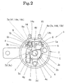
- Fig. 2 is a front view of a state where members are attached to a casing;
- Fig. 3 is a rear view of the horn;
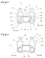
- Fig. 4(A) is a front view of a terminal unit, and Fig. 4(B) is a rear view of the terminal unit; and
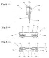
- Fig. 5 (A) is a cross sectional view taken along line X-X in Fig. 4 (A), Fig. 5 (B) is a plan view of Fig. 4(A), and Fig. 5(C) is a cross sectional view taken along line X-X in Fig. 4(B).
- Next, an embodiment of the present invention will be described hereinafter with reference to Figs. 1 to 5.
- In the figures, the
reference numeral 1 denotes a vehicle horn. Acasing 2 for thehorn 1 is formed cylindrically with a bottom. Arecessed part 2b projecting outwardly is formed on the center part of abottom piece part 2a of thecasing 2. A fixediron core 3 penetrates an axially center part of therecessed part 2b and is supported position-adjustably in an axial direction by afixing nut 3a. - The
reference numeral 4 denotes a coil bobbin. Thecoil bobbin 4 is composed of a cylinder 4a andflanges 4b, which are extended to outer diameter sides from both ends of the cylinder 4a, respectively, and are integrally formed with the cylinder 4a. An exciting coil C is constituted in such a manner that a winding 5 is wound around the periphery of the cylinder 4a. Thecoil bobbin 4 is housed in therecessed part 2b with the fixediron core 3 being inserted into the cylinder 4a and theflanges 4b being supported by thebottom piece part 2a of thecasing 2. Further, anattachment piece part 4c and a terminalfixing piece part 4d, which are faced to each other in radial direction and project toward an outer diameter, are integrally formed on a peripheral edge of theflange 4b of thecoil bobbin 4 at the opening side of thecasing 2. Theattachment piece part 4c is fixed to an outer diameter sidebottom piece part 2c formed at an outer diameter side of the recessedpart 2b of thecasing 2 via apin 2d. - The
terminal fixing part 4d is arranged at a facing part of a pair of throughholes bottom piece part 2c. A pair of throughholes holes end 5a of the winding 5, constituting the exciting coil C, is pulled out and wired from the coil bobbin cylinder 4a in the vicinity of the throughhole 4e of the pair of throughholes terminal pin 6, made of a conductive member, is provided so as to penetrate coil bobbin through'hole 4e and the casing throughhole 2e. Therefore the windingend 5a is electrically connected to the firstterminal pin 6. - Additionally, the
other end 5b of the winding 5 of the exciting coil C is pulled out and wired from the cylinder 4a in the vicinity of the coil bobbin throughhole 4f. Further, abase end 7b of a fixingplate 7, which is constituted by the conductive plate member and in which a throughhole 7a is opened, and abase end 8b of amovable plate 8, which is constituted by the conductive plate member and in which a throughhole 8a is opened, are provided aside of the throughhole 4f. A secondterminal pin 9, made of a conductive member, is provided so as to penetrate the coil bobbin throughhole 4f, the fixing plate throughhole 7a, the movable throughhole 8a and the casing throughhole 2f, respectively. With these structures, the fixingplate 7 is set to be electrically connected to the secondterminal pin 9 and themovable plate 8 is set to be insulated from the secondterminal pin 9, and themovable plate 8 is set to be electrically connected to the other windingend 5b. In addition, an insulatingmaterial 10 is interposed between the fixingplate 7 and themovable plate 8, and therefore the fixingplate 7 is insulated from themovable plate 8. Moreover, atop end 7c of the fixingplate 7 is fixed by a fixingpiece 4g extended from theflange 4b of thecoil bobbin 4 at the opening side of thecasing 2. - A fixed
contact 7d is formed on the fixingplate 7 so as to project toward themovable plate 8 side, amovable contact 8c, facing the fixedcontact 7d, is formed on themovable plate 8 so as to project toward the fixingplate 7 side. Themovable contact 8c is brought into contact with and electrically connected to the fixedcontact 7d in the natural state. Thus, when electric power is supplied via the first and second terminal pins 6, 9 in the contact state, electric power is supplied to the exciting coil C. - A peripheral edge of a
diaphragm 11 is integrally fixed to an opening edge of thecasing 2, and a long shaft-shapedmovable iron core 12 is integrally provided at the center of thediaphragm 11. Anend surface 12a of themovable iron core 12 is arranged so as to adjacently face an end surface (inside top end surface) 3b of the fixediron core 3 inside thecasing 2 with a predetermined gap G. Further, as described above, the exciting coil C is supplied with the electric power to magnetize the fixediron core 3 so that themovable iron core 12 is attracted to the fixediron core 3 based on the flexibility of thediaphragm 11 and displaced. - A
step 12b is formed on a peripheral surface of themovable iron core 12. Thestep 12b forcibly displaces themovable plate 8 in a direction where it moves away from the fixedplate 7, based on the displacement of themovable iron core 12 toward the fixediron core 3 side, and causes themovable contact 8c move away from the fixedcontact 7d. In this state, the exciting coil C is not energized and degaussed. -
Reference numeral 13 denotes a terminal unit (corresponding to the terminal member of the present invention) in which penetrating top ends of the first and second terminal pins 6, 9, projecting toward the outer surface of the casing outer diameter sidebottom piece part 2c, are housed. Acase body 14, constituting theterminal unit 13, includes abottom piece 14a along the casing outer diameter sidebottom piece part 2c and is formed in a box-shape, and a space S is formed betweenside pieces side pieces holes side pieces holes casing 2 penetrate the throughholes holes terminal plates - A
capacitor 17, which is a noise preventing member, is housed in the space S formed between theside pieces case body 14. A pair of connectinglines capacitor 17 are electrically connected to the first and secondterminal plates notches side pieces noise preventing member 17 is arranged in such wiring state as to be connected to a contact part of the fixedcontact 7d and themovable contact 8c in parallel. - The space S, in which the
noise preventing member 17 is provided, is then filled with an insulatingresin material 18, and thus thenoise preventing member 17 is encased by theresin material 18. - With the structure mentioned above the
terminal unit 13 is attached to thecasing 2 in the following manner. Namely, thebottom piece 14a is brought into contact with the casing outer diameter sidebottom piece part 2c, theresin material 18 filling side is exposed outside, the first and second terminal pins 6, 9 projecting outwardly from the casing outer diameter sidebottom piece part 2c are inserted into the casing throughholes holes casing 2, thecoil bobbin 4, the fixingplate 7, themovable plate 8, the one windingend 5a and the other windingend 5b are electrically connected to each other as described above and integrally fixed. The first and second terminal pins 6, 9 are electrically connected to the first and secondterminal plates terminal unit 13 is integrally fixed to thecasing 2 by one caulking operation. - Here, a side piece (inner radial side piece) 14h at an inner radial side of the
case body 14 is formed in an arc-shape so as to adjacently face the peripheral surface of the casing recessedpart 2b. The thickness T of thecase body 14 in an axial direction (the thickness in a box depth direction) is set so as to be smaller than the projecting amount of the casing recessedpart 2b toward the outside. Theterminal unit 13 is set so as to not projecting further outside than thebottom piece part 2a when attached to the casing. - Moreover, ends of the first and second
terminal plates side piece 14i at the outer radial side of casingbody 14. An outer coupler (not shown) is fitted with the projecting part. Electric power is supplied to the first and second terminal pins 6, 9 via the first and secondterminal plates - In the
horn 1 thus structured, when the switching operation (not shown) is performed, the electric power is supplied to the first and second terminal pins 6, 9, the exciting coil C is energized and excited via the fixedcontact 7d and themovable contact 8c being brought into contact with each other, and themovable iron core 12 is displaced toward the fixediron core 3 side. Thus, themovable contact 8c moves away from the fixedcontact 7d, and the exciting coil C no longer is energized. Then themovable iron coil 12 moves away from the fixediron core 3, and thus themovable contact 8c again comes into contact with the fixedcontact 7d and the exciting coil C is excited. A warning sound is generated by repeating this operation. - As described above, in the embodiment structured as the above, when the electric power is supplied to the first and second terminal pins 6, 9 via the first and second
terminal plates fixed contact 7d and themovable contact 8c is repeated and the warning sound is generated. In this case, because thenoise preventing member 17 is connected to the fixedcontact 7d andmovable contact 8c in parallel, the noise due to the repeated intermittent switching between thefixed contact 7d and themovable contact 8c is prevented and ahorn 1 having excellent performance can be obtained. - In this case, the
noise preventing member 17 is not provided in the cylinder of thecasing 2, but is housed in theterminal unit 13 which is provided outside of thecasing 2 in order to supply the electric power. Thus , thenoise preventing member 17 is not affected by the atmosphere temperature in thecasing 2 and is protected based on its own heat resistance to temperature. Further, it is unnecessary to ensure an exclusive space in the cylinder of thecasing 2 for the noise preventing member so that the casing can be miniaturized. Furthermore, it is unnecessary to provide an exclusive member for attachment of the noise preventing member, the structure inside the cylinder of thecasing 2 can be simplified, and cost can be reduced. - Additionally, because the
noise preventing member 17 is provided in the space S between theterminal plates noise preventing member 17. - Additionally, because the
noise preventing member 17 can be built in theterminal unit 13 together with the first and secondterminal plates terminal plates terminal unit 13 to be attached to thecasing 2, the wiring of thenoise preventing member 17 and assembling work are simplified, and thehorn 1 can be effectively manufactured. - Additionally, because the thickness of the
terminal unit 13 in the axial direction is set so as to not be larger than the projecting amount of the recessedpart 2b of thecasing 2, there is no problem such that the space for provision of thehorn 1 is enlarged by theterminal unit 13. As a result, the space between thehorn 1 and members provided in the vicinity can be reduced when thehorn 1 is provided. - Further, the
noise preventing member 17 is provided in the space S formed between encased parts, which face each other, of the first and secondterminal plates terminal unit 13. The space S is filled with theresin material 18 so that thenoise preventing member 17 is encased in and integrally fixed to theterminal unit 13. Thus, thenoise preventing member 17 can be protected, a problem such as thenoise preventing member 17 falling off as a result of vibration is avoided, and thenoise preventing member 17 can be reliably fixed. - Additionally, when forming a product in which the
noise preventing member 17 is to be provided and a product in which themember 17 is not to be provided, it is only required to prepare theterminal unit 13 in which thenoise preventing member 17 is included and the terminal 13 in which themember 17 is not included. That is, the specification of thecasing 2 side does not vary for each product. Thus, components can be made in common and low-cost can be realized. In addition, quality management can be simplified. Further, when theterminal unit 13 in which thenoise preventing member 17 is included and the terminal 13 in which themember 17 is not included are formed, it is only required to form two types of terminal units of which the shapes of the parts exposed outside are different from each other. Thus, it is not necessary to attach identifying marks to identify whether the horn is provided with the noise preventing member or the horn is not provided with the noise preventing member, and distinguishing the two different terminal units is easy. - Moreover, the present invention, as a matter of course, is not limited to the above described embodiment. One sheet of a terminal plate is provided in the terminal member in the case of a horn in which a body ground is performed. However, even in this case, a space can be provided adjacently to the terminal plate, the noise preventing member can be built in the space, and the space can be filled with the resin material. Thus, similar to the above described embodiment, the noise preventing member can be protected against the atmospheric temperature, etc., and can be reliably fixed or positioned.
- As described above, a vehicle horn according to the present invention serves as a horn that is mounted on a general-purpose type vehicle such as a car and a motorcycle, a special-purpose vehicle or the like, and is, in particular, suitable for the general-purpose type vehicle.
Claims (5)
- A vehicle horn in which a recessed part projected outside is formed on a bottom piece part of a cylindrical casing with a bottom, a coil bobbin of an exciting coil is housed in the recessed part and a terminal member provided with terminal plates for supplying electric power to a winding of the exciting coil is arranged on an outer surface of the bottom piece part of the casing, wherein a noise preventing member is provided in the terminal member.
- The vehicle horn according to claim 1, wherein the terminal member is provided with a pair of terminal plates, and the noise preventing member is provided between the pair of terminal plates.
- The vehicle horn according to claim 1 or 2, wherein the terminal member is made as a terminal unit in which the noise preventing member is built beforehand, and the terminal unit is attached to a radially outer side part of a recessed part of the bottom piece part of the casing.
- The vehicle horn according to claim 1, 2 or 3, wherein the terminal member is provided so as not to project further outwardly than the recessed part of the bottom piece part of the casing.
- The vehicle horn according to claim 1, 2, 3 or 4, wherein the noise preventing member is provided in a space formed in the terminal member, and the space is filled with a resin material.
Applications Claiming Priority (2)
| Application Number | Priority Date | Filing Date | Title |
|---|---|---|---|
| JP2004004340A JP4299153B2 (en) | 2004-01-09 | 2004-01-09 | Vehicle horn |
| PCT/JP2005/000440 WO2005066931A1 (en) | 2004-01-09 | 2005-01-07 | Horn for vehicle |
Publications (1)
| Publication Number | Publication Date |
|---|---|
| EP1703490A1 true EP1703490A1 (en) | 2006-09-20 |
Family
ID=34747114
Family Applications (1)
| Application Number | Title | Priority Date | Filing Date |
|---|---|---|---|
| EP05703679A Withdrawn EP1703490A1 (en) | 2004-01-09 | 2005-01-07 | Horn for vehicle |
Country Status (4)
| Country | Link |
|---|---|
| US (1) | US20080048843A1 (en) |
| EP (1) | EP1703490A1 (en) |
| JP (1) | JP4299153B2 (en) |
| WO (1) | WO2005066931A1 (en) |
Family Cites Families (9)
| Publication number | Priority date | Publication date | Assignee | Title |
|---|---|---|---|---|
| JPS5928475Y2 (en) * | 1978-11-20 | 1984-08-16 | 松下電器産業株式会社 | Buzzer |
| US5145413A (en) * | 1990-07-24 | 1992-09-08 | Yazaki Corporation | Noise suppressing connector |
| JP2565313Y2 (en) * | 1991-12-03 | 1998-03-18 | 株式会社ミツバ | Mounting structure of noise prevention element for vehicle horn |
| JP3207717B2 (en) * | 1995-07-06 | 2001-09-10 | 京セラミタ株式会社 | Coil bobbin and excitation coil |
| EP0984463B1 (en) * | 1997-05-23 | 2003-03-19 | Hitachi, Ltd. | Ignition coil unit for engine and engine provided with plastic head cover |
| JP2000318517A (en) * | 1999-05-07 | 2000-11-21 | Mitsuba Corp | Horn for vehicles |
| JP2002272019A (en) * | 2001-03-08 | 2002-09-20 | Sumitomo Wiring Syst Ltd | Power supply and transmission / reception device for handle |
| US6759460B2 (en) * | 2001-03-08 | 2004-07-06 | Asahi Kasei Kabushiki Kaisha | Resin composition |
| JP3933898B2 (en) * | 2001-09-21 | 2007-06-20 | 三井金属鉱業株式会社 | Vehicle door lock device |
-
2004
- 2004-01-09 JP JP2004004340A patent/JP4299153B2/en not_active Expired - Fee Related
-
2005
- 2005-01-07 WO PCT/JP2005/000440 patent/WO2005066931A1/en not_active Ceased
- 2005-01-07 EP EP05703679A patent/EP1703490A1/en not_active Withdrawn
- 2005-01-07 US US10/584,939 patent/US20080048843A1/en not_active Abandoned
Non-Patent Citations (1)
| Title |
|---|
| See references of WO2005066931A1 * |
Also Published As
| Publication number | Publication date |
|---|---|
| JP4299153B2 (en) | 2009-07-22 |
| US20080048843A1 (en) | 2008-02-28 |
| WO2005066931A1 (en) | 2005-07-21 |
| JP2005196053A (en) | 2005-07-21 |
Similar Documents
| Publication | Publication Date | Title |
|---|---|---|
| JP5018319B2 (en) | Ignition coil | |
| JP4975173B1 (en) | Ignition coil device for internal combustion engine | |
| US8737660B2 (en) | Electric horn | |
| US7626481B2 (en) | Ignition coil | |
| JP2002272050A (en) | Resolver stator structure | |
| US20080048843A1 (en) | Vehicle Horn | |
| JP2000130303A (en) | Ignition coil | |
| JP4376062B2 (en) | Electronic module for ignition coil of internal combustion engine | |
| JP3629983B2 (en) | Ignition coil | |
| JP4457926B2 (en) | Ignition coil | |
| JPH03117683A (en) | High pressure induction device for internal combustion engine ignition coil for automobile | |
| JP4747987B2 (en) | Ignition coil | |
| US7441552B1 (en) | Ignition coil apparatus for an internal combustion engine | |
| JP2003347137A (en) | Ignition device for internal combustion engine | |
| JPS6047406A (en) | Ignition device for internal combustion engine | |
| JP3740682B2 (en) | Motor terminal device | |
| JP3546991B2 (en) | Method of manufacturing ignition coil and secondary spool | |
| JP4462076B2 (en) | Ignition coil | |
| EP1457671A1 (en) | Ignition coil assembly | |
| JP3890457B2 (en) | Terminal welding method | |
| JP4262930B2 (en) | Ignition coil for internal combustion engine | |
| US20080202484A1 (en) | Ignition coil for an internal combustion engine | |
| JPS6015309Y2 (en) | Molded internal combustion engine ignition system | |
| KR100560758B1 (en) | Automotive Ignition Coil | |
| JPS6012261Y2 (en) | Molded internal combustion engine ignition system |
Legal Events
| Date | Code | Title | Description |
|---|---|---|---|
| PUAI | Public reference made under article 153(3) epc to a published international application that has entered the european phase |
Free format text: ORIGINAL CODE: 0009012 |
|
| 17P | Request for examination filed |
Effective date: 20060704 |
|
| AK | Designated contracting states |
Kind code of ref document: A1 Designated state(s): DE IT |
|
| DAX | Request for extension of the european patent (deleted) | ||
| RBV | Designated contracting states (corrected) |
Designated state(s): DE IT |
|
| STAA | Information on the status of an ep patent application or granted ep patent |
Free format text: STATUS: THE APPLICATION HAS BEEN WITHDRAWN |
|
| 18W | Application withdrawn |
Effective date: 20080822 |