EP1703264A2 - Load detection device - Google Patents
Load detection device Download PDFInfo
- Publication number
- EP1703264A2 EP1703264A2 EP06110856A EP06110856A EP1703264A2 EP 1703264 A2 EP1703264 A2 EP 1703264A2 EP 06110856 A EP06110856 A EP 06110856A EP 06110856 A EP06110856 A EP 06110856A EP 1703264 A2 EP1703264 A2 EP 1703264A2
- Authority
- EP
- European Patent Office
- Prior art keywords
- sensor element
- driving
- load
- vibration
- signal
- Prior art date
- Legal status (The legal status is an assumption and is not a legal conclusion. Google has not performed a legal analysis and makes no representation as to the accuracy of the status listed.)
- Granted
Links
- 238000001514 detection method Methods 0.000 title claims abstract description 37
- 230000001133 acceleration Effects 0.000 claims abstract description 18
- 239000000284 extract Substances 0.000 claims description 2
- 238000010586 diagram Methods 0.000 description 4
- 239000002131 composite material Substances 0.000 description 2
- 230000003247 decreasing effect Effects 0.000 description 2
- 230000001419 dependent effect Effects 0.000 description 2
- 230000005856 abnormality Effects 0.000 description 1
- 238000005259 measurement Methods 0.000 description 1
- 238000000034 method Methods 0.000 description 1
- 230000029058 respiratory gaseous exchange Effects 0.000 description 1
- 238000000926 separation method Methods 0.000 description 1
Images



Classifications
-
- G—PHYSICS
- G01—MEASURING; TESTING
- G01L—MEASURING FORCE, STRESS, TORQUE, WORK, MECHANICAL POWER, MECHANICAL EFFICIENCY, OR FLUID PRESSURE
- G01L1/00—Measuring force or stress, in general
- G01L1/16—Measuring force or stress, in general using properties of piezoelectric devices
- G01L1/162—Measuring force or stress, in general using properties of piezoelectric devices using piezoelectric resonators
-
- G—PHYSICS
- G01—MEASURING; TESTING
- G01G—WEIGHING
- G01G19/00—Weighing apparatus or methods adapted for special purposes not provided for in the preceding groups
- G01G19/40—Weighing apparatus or methods adapted for special purposes not provided for in the preceding groups with provisions for indicating, recording, or computing price or other quantities dependent on the weight
- G01G19/413—Weighing apparatus or methods adapted for special purposes not provided for in the preceding groups with provisions for indicating, recording, or computing price or other quantities dependent on the weight using electromechanical or electronic computing means
- G01G19/414—Weighing apparatus or methods adapted for special purposes not provided for in the preceding groups with provisions for indicating, recording, or computing price or other quantities dependent on the weight using electromechanical or electronic computing means using electronic computing means only
- G01G19/4142—Weighing apparatus or methods adapted for special purposes not provided for in the preceding groups with provisions for indicating, recording, or computing price or other quantities dependent on the weight using electromechanical or electronic computing means using electronic computing means only for controlling activation of safety devices, e.g. airbag systems
-
- G—PHYSICS
- G01—MEASURING; TESTING
- G01G—WEIGHING
- G01G3/00—Weighing apparatus characterised by the use of elastically-deformable members, e.g. spring balances
- G01G3/12—Weighing apparatus characterised by the use of elastically-deformable members, e.g. spring balances wherein the weighing element is in the form of a solid body stressed by pressure or tension during weighing
- G01G3/13—Weighing apparatus characterised by the use of elastically-deformable members, e.g. spring balances wherein the weighing element is in the form of a solid body stressed by pressure or tension during weighing having piezoelectric or piezoresistive properties
-
- G—PHYSICS
- G01—MEASURING; TESTING
- G01G—WEIGHING
- G01G3/00—Weighing apparatus characterised by the use of elastically-deformable members, e.g. spring balances
- G01G3/12—Weighing apparatus characterised by the use of elastically-deformable members, e.g. spring balances wherein the weighing element is in the form of a solid body stressed by pressure or tension during weighing
- G01G3/16—Weighing apparatus characterised by the use of elastically-deformable members, e.g. spring balances wherein the weighing element is in the form of a solid body stressed by pressure or tension during weighing measuring variations of frequency of oscillations of the body
- G01G3/165—Constructional details
Definitions
- This invention generally relates to a load detecting device. More particularly, this invention pertains to a load detecting device for detecting a load or an acceleration applied to a supporting member.
- a known load detecting device detects, using a piezoelectric element, not only a presence of a human body but also abnormality in a human body by extracting a human body-specific vibration component caused by heartbeat, breathing, and the like.
- JP2000-230853A discloses a load detecting device including a vibration detecting means, a vibration characteristics calculating means, and a load calculating means.
- the vibration detecting means is arranged on a supporting member for supporting a human body and including a vibration generating portion and a vibration detecting portion provided adjacent to each other.
- the vibration characteristics calculating means calculates vibration characteristics through propagation of vibration generated by the vibration generating portion on the basis of an output signal from the vibration detecting portion.
- the load calculating means calculates a load applied to the vibration detecting means based on an output signal from the vibration characteristic calculating means.
- the vibration generating portion and the vibration detecting portion are both constituted by piezoelectric element.
- the load detecting device can be installed in a small space with the least trouble accordingly.
- a load detecting device including a sensor element arranged on a supporting member, a driving portion for outputting a driving signal for vibrating the sensor element, a vibration detecting portion for extracting the detection signal from the sensor element and for detecting a vibration characteristic value of the sensor element based on the detection signal extracted, and a calculating portion for calculating one of or both of a load and an acceleration applied to the sensor element based on the vibration characteristic value from the vibration detecting portion
- the load detecting device further includes a wiring for electrically connecting the sensor element, the driving portion and the vibration detecting portion to one another, and for transmitting a superimposed signal constituted by superposition of the driving signal from the driving portion and the detection signal from the sensor element
- the sensor element includes a function for generating and detecting a vibration within a single element and converts a load or an acceleration applied to the supporting member into a detection signal.
- a driving signal and a detection signal of the sensor element are transmitted in a superimposed manner, i.e. as a superimposed signal.
- a vibration generating portion and a vibration detecting portion can be constituted by a single sensor element which is conventionally constituted separately and individually.
- the sensor element and the wiring can be simplified, which leads to a reduction of cost.
- Fig. 1 is a block diagram of a structure of a load detecting device according to a first embodiment of the present invention
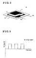
- Fig. 2 is a perspective view of a sensor element of the load detecting device according to the first embodiment of the present invention
- Fig. 3 is a graph showing a waveform of a driving signal of the load detecting device according to the first embodiment of the present invention
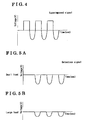
- Fig. 4 is a graph showing a waveform of an electrical signal on a wiring of the load detecting device according to the first embodiment of the present invention
- Fig. 5A and 5B are graphs each showing a waveform of a detection signal of the load detecting device according to the first embodiment of the present invention
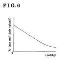
- Fig. 6 is a graph showing a characteristics of relationship between a load and a voltage amplitude value according to the first embodiment of the present invention
- Fig. 7A and 7B are views each showing a principle of the load detecting device according to the first embodiment of the present invention.
- Fig. 8 is a block diagram of a structure of the load detecting device according to a second embodiment of the present invention.
- FIG. 1 is a block diagram showing a structure of the load detecting device according to the first embodiment.
- Fig. 2 is a perspective view of a sensor element of the load detecting device.
- Fig. 3 is a graph showing a waveform of a driving signal of the load detecting device.
- Fig. 4 is a graph showing a waveform of an electric signal on a wiring of the load detecting device.
- Figs. 5A and 5B are graphs each showing a waveform of a detection signal of the load detecting device.
- Fig. 6 is a graph showing a characteristic of relationship between a load and a voltage amplitude value of the load detecting device.
- a load detecting device 1 detects a load or an acceleration (i.e. rate of load change) applied to a supporting member such as a seating face and a seatback of a vehicular seat and a chair for supporting a human body.
- the load detecting device 1 includes a sensor element 10, a driving portion 20, a vibration detecting portion 30, and a calculating portion 40.
- the sensor element 10 is arranged on the supporting member for supporting a human body so as to convert a load or an acceleration applied to the supporting member into a detection signal.
- the sensor element 10 has a function for generating and detecting vibration within a single element.
- the sensor element 10 is constituted by at least one cell attached onto a board 11.
- the cell includes a piezoelectric member 13 whose upper and lower faces are equipped with a first electrode 12 and a second electrode 14 respectively as shown in Fig. 2.
- a wiring 15a is electrically connected to the first electrode 12 while a wiring 15b is electrically connected to the second electrode 14 as shown in Fig. 2. It is preferred that one of the wirings 15a and 15b is earthed.
- the piezoelectric member 13 When a driving voltage is periodically applied between the first electrode 12 and the second electrode 14 from the driving portion 20, the piezoelectric member 13 is expanded or contracted, which causes deflection or deformation of the board 11. Further, on the contrary, when the board 11 is deflected or deformed because of a load or an acceleration applied from the outside, the piezoelectric member 13 is also deformed. An electric potential difference (i.e. electric charge) is generated between the first electrode 12 and the second electrode 14 and then a detection signal related to the load or the acceleration is output from the sensor element 10.
- an electric potential difference i.e. electric charge
- the driving portion 20 causes the sensor element 10 to vibrate so that the deflection or deformation thereof is caused by periodically applying a driving voltage, i.e. by outputting a driving signal, to the sensor element 10.
- the driving portion 20 periodically applies the driving voltage at a predetermined level to the sensor element 10.
- the driving portion 20 is electrically connected to a wiring 15 such as the wiring 15a and the wiring 15b, during a period in which the driving portion 20 outputs the driving voltage.
- the driving portion 20 is electrically disconnected from the wiring 15 during a period in which the driving portion 20 does not output the driving voltage.
- an on/off cycle of the driving voltage i.e. frequency of the driving voltage, can be used as a resonance frequency of the sensor element 10 so as to effectively vibrate the sensor element 10.
- the vibration detecting portion 30 converts a detection signal from the sensor element 10 into a voltage amplitude value.
- the vibration detecting portion 30 that is electrically connected to the wiring 15 extracts a detection signal sent from the sensor element 10 among an input signal to the vibration detecting portion 30 which includes a driving signal from the driving portion 20, i.e. a superimposed signal, for the purposes of converting the detection signal extracted into a vibration characteristic value such as a voltage amplitude value.
- a peak of voltage i.e. detection voltage
- a peak of voltage is downwardly large when a load is small as shown in Fig. 5A while a peak of voltage is downwardly small when a load is large as shown in Fig. 5B.
- the calculating portion 40 calculates a load based on a voltage amplitude value from the vibration detecting portion 30.
- the calculating portion 40 that is electrically connected to the vibration detecting portion 30 by means of a wiring calculates a load corresponding to a voltage amplitude value from the vibration detecting portion 30 based on a map as shown in Fig. 6. At this time, the voltage amplitude value is maximized when the load is zero, and is decreased in association with increase of the load.
- FIGS. 7A and 7B are views for each explaining a principle of the load detecting device 1 of the present embodiment.
- the sensor element 10 is deflected or deformed because of application of a predetermined driving voltage.
- the deformation amount of the sensor element 10 depends on a load applied thereto. Further, when the driving voltage is turned off, the sensor element 10 returns to its initial state with the load applied thereto. At this time, an electric charge in response to the deformation amount of the sensor element 10 previously obtained (which corresponds to a detection signal) is output from the sensor element 10. Accordingly, the deformation amount of the sensor element 10 is acquired by measuring the electric charge from the sensor element 10 after the driving voltage is turned off. In other wards, the deformation amount of the sensor element 10 is acquired by measuring the electric potential difference between the first electrode 12 and second electrode 14. The load applied to the sensor element 10 is eventually obtained.
- a method of driving and detection performed by the sensor element 10 for measuring a load applied thereto on the basis of the aforementioned principle is explained below.
- the driving voltage is applied to the sensor element 10 from the driving portion 20 by means of the wiring 15 as shown in Fig. 7A.
- the sensor element 10 is deflected or deformed to a point at which a deflection force generated by the driving voltage and a load applied to the sensor element 10 are balanced out.
- the deflection of the sensor element 10 is small when the load is large as shown in Fig. 7B and is large when the load is small as shown in Fig. 7A.
- the driving portion 20 is disconnected from the wiring 15.
- the deflection force in the sensor element 10 disappears, which cause the sensor element 10 to return to the initial state (i.e. initial position) thereof.
- an electric charge Q in response to the deformation amount obtained in the driving period is output from the sensor element 10.
- the electric charge Q (the electric potential difference between the first electrode 12 and the second electrode 14) is output as a detection signal from the sensor element 10 and transmitted to the vibration detecting portion 30 by means of the wiring 15.
- the detection signal is converted into a voltage amplitude value by the vibration detecting portion 30.
- the load is calculated accordingly by the calculating portion 40 on the basis of the voltage amplitude value obtained.
- the function of the driving portion 20 is deactivated. Then, an amount of electric charge from the sensor element 10 (the electric potential difference between the first electrode 12 and the second electrode 14) is measured by the vibration detecting portion 30, and the electric charge measured is converted into the acceleration by the calculating portion 40.
- a composite waveform that combines load-dependent and acceleration-dependent voltage waveform is output from the vibration detecting portion 30. Then, frequency separation is conducted on the composite waveform by the calculating portion 40 to thereby enable detection of the load and the acceleration at the same time.
- a driving signal and a detection signal of the sensor element 10 are transmitted in a superimposed manner, i.e. as a superimposed signal.
- a vibration generating portion and a vibration detecting portion can be constituted by a single sensor element which is conventionally constituted separately and individually.
- the sensor element 10 and the wiring can be simplified, which leads to a reduction of cost.
- FIG. 8 is a block diagram showing a structure of the load detecting device according to the second embodiment.
- each sensor element 10 is electrically connected to a connection switching portion 50 by means of a first wiring 15.
- the connection switching portion 50 is also electrically connected to the driving portion 20 and the vibration detecting portion 30 by means of a second wiring 51, and to the calculating portion 40 by means of a third wiring 52.
- Structures of the sensor element 10, the driving portion 20, and the vibration detecting portion 30 according to the second embodiment are same as those according to the first embodiment.
- the calculating portion 40 calculates a load applied to the sensor elements 10 based on a voltage amplitude value from the vibration detecting portion 30.
- the calculating portion 40 is electrically connected to the vibration detecting portion 30 by means of a wiring so as to calculate a load corresponding to the voltage amplitude value from the vibration detecting portion 30 based on a map, as in the same way as the first embodiment.
- the calculating portion 40 outputs a switching signal for switching an electric connection state with a specified sensor element 10.
- connection switching portion 50 switches the electric connection state with the first wiring 15 on the basis of a switching signal from the calculating portion 40.
- the connection switching portion 50 is electrically connected to the driving portion 20 and the vibration detecting portion 30 by means of the second wiring 51. Further, the connection switching portion 50 is electrically connected to the calculating portion 40 by means of the third wiring 52.
- connection switching portion 50 is first operated by means of a switching signal from the calculating portion 40. Then, the connection switching portion 50 connects the specified sensor element 10, and the driving portion 20 and the vibration detecting portion 30 one another so that a voltage amplitude value is input from the vibration detecting portion 30 to the calculating portion 40. The load on the specified sensor element 10 is calculated accordingly. This operation is sequentially conducted on the respective sensor elements 10 so as to measure distribution of load on a face of the supporting member 2.
- a load detecting device (1) including a sensor element (10), a driving portion (20) for outputting a driving signal for vibrating the sensor element, a vibration detecting portion (30) for extracting the detection signal and detecting a vibration characteristic value of the sensor element, a wiring (15, 15a, 15b) for electrically connecting the sensor element, the driving portion and the vibration detecting portion to one another, and for transmitting a superimposed signal constituted by superposition of the driving signal and the detection signal, and a calculating portion (40) for calculating one of or both of a load and an acceleration applied to the sensor element based on the vibration characteristic value characterized in that the sensor element includes a function for generating and detecting a vibration within a single element and converts a load or an acceleration applied to the supporting member into a detection signal.
Landscapes
- Physics & Mathematics (AREA)
- General Physics & Mathematics (AREA)
- Engineering & Computer Science (AREA)
- Mathematical Physics (AREA)
- Theoretical Computer Science (AREA)
- Force Measurement Appropriate To Specific Purposes (AREA)
- Measurement Of Mechanical Vibrations Or Ultrasonic Waves (AREA)
Abstract
Description
- This invention generally relates to a load detecting device. More particularly, this invention pertains to a load detecting device for detecting a load or an acceleration applied to a supporting member.
- A known load detecting device detects, using a piezoelectric element, not only a presence of a human body but also abnormality in a human body by extracting a human body-specific vibration component caused by heartbeat, breathing, and the like. For example,
JP2000-230853A - According to the load detecting device disclosed, however, since vibration is generated by one piezoelectric element and then the vibration is detected by other piezoelectric element, a piezoelectric member for generating vibration and a piezoelectric member for detecting the vibration are separately required. Thus, in order to measure distribution of load applied to a face of the supporting member and the like, a great number of pair of piezoelectric members for generating and detecting the vibration are necessary, which leads to complication of a structure and increase of a cost of the device.
- Thus, a need exists for a load detecting device whose structure remains simple at a time of detection of distribution of load, and cost can be decreased.
- According to an aspect of the present invention, a load detecting device including a sensor element arranged on a supporting member, a driving portion for outputting a driving signal for vibrating the sensor element, a vibration detecting portion for extracting the detection signal from the sensor element and for detecting a vibration characteristic value of the sensor element based on the detection signal extracted, and a calculating portion for calculating one of or both of a load and an acceleration applied to the sensor element based on the vibration characteristic value from the vibration detecting portion characterized in that the load detecting device further includes a wiring for electrically connecting the sensor element, the driving portion and the vibration detecting portion to one another, and for transmitting a superimposed signal constituted by superposition of the driving signal from the driving portion and the detection signal from the sensor element, and the sensor element includes a function for generating and detecting a vibration within a single element and converts a load or an acceleration applied to the supporting member into a detection signal.
- According to the aforementioned invention, a driving signal and a detection signal of the sensor element are transmitted in a superimposed manner, i.e. as a superimposed signal. Thus, a vibration generating portion and a vibration detecting portion can be constituted by a single sensor element which is conventionally constituted separately and individually. The sensor element and the wiring can be simplified, which leads to a reduction of cost.
- The foregoing and additional features and characteristics of the present invention will become more apparent from the following detailed description considered with reference to the accompanying drawings, wherein:
- Fig. 1 is a block diagram of a structure of a load detecting device according to a first embodiment of the present invention;
- Fig. 2 is a perspective view of a sensor element of the load detecting device according to the first embodiment of the present invention;
- Fig. 3 is a graph showing a waveform of a driving signal of the load detecting device according to the first embodiment of the present invention;
- Fig. 4 is a graph showing a waveform of an electrical signal on a wiring of the load detecting device according to the first embodiment of the present invention;
- Fig. 5A and 5B are graphs each showing a waveform of a detection signal of the load detecting device according to the first embodiment of the present invention;
- Fig. 6 is a graph showing a characteristics of relationship between a load and a voltage amplitude value according to the first embodiment of the present invention;
- Fig. 7A and 7B are views each showing a principle of the load detecting device according to the first embodiment of the present invention; and
- Fig. 8 is a block diagram of a structure of the load detecting device according to a second embodiment of the present invention.
- A first embodiment of a load detecting device is explained with reference to the attached drawings. Fig. 1 is a block diagram showing a structure of the load detecting device according to the first embodiment. Fig. 2 is a perspective view of a sensor element of the load detecting device. Fig. 3 is a graph showing a waveform of a driving signal of the load detecting device. Fig. 4 is a graph showing a waveform of an electric signal on a wiring of the load detecting device. Figs. 5A and 5B are graphs each showing a waveform of a detection signal of the load detecting device. Fig. 6 is a graph showing a characteristic of relationship between a load and a voltage amplitude value of the load detecting device.
- A
load detecting device 1 detects a load or an acceleration (i.e. rate of load change) applied to a supporting member such as a seating face and a seatback of a vehicular seat and a chair for supporting a human body. As shown in Fig. 1, theload detecting device 1 includes asensor element 10, adriving portion 20, avibration detecting portion 30, and a calculatingportion 40. - The
sensor element 10 is arranged on the supporting member for supporting a human body so as to convert a load or an acceleration applied to the supporting member into a detection signal. Thesensor element 10 has a function for generating and detecting vibration within a single element. Thesensor element 10 is constituted by at least one cell attached onto aboard 11. The cell includes apiezoelectric member 13 whose upper and lower faces are equipped with afirst electrode 12 and asecond electrode 14 respectively as shown in Fig. 2. Awiring 15a is electrically connected to thefirst electrode 12 while awiring 15b is electrically connected to thesecond electrode 14 as shown in Fig. 2. It is preferred that one of thewirings first electrode 12 and thesecond electrode 14 from thedriving portion 20, thepiezoelectric member 13 is expanded or contracted, which causes deflection or deformation of theboard 11. Further, on the contrary, when theboard 11 is deflected or deformed because of a load or an acceleration applied from the outside, thepiezoelectric member 13 is also deformed. An electric potential difference (i.e. electric charge) is generated between thefirst electrode 12 and thesecond electrode 14 and then a detection signal related to the load or the acceleration is output from thesensor element 10. - As shown in Figs. 1 and 3, the
driving portion 20 causes thesensor element 10 to vibrate so that the deflection or deformation thereof is caused by periodically applying a driving voltage, i.e. by outputting a driving signal, to thesensor element 10. Thedriving portion 20 periodically applies the driving voltage at a predetermined level to thesensor element 10. Thedriving portion 20 is electrically connected to awiring 15 such as thewiring 15a and thewiring 15b, during a period in which thedriving portion 20 outputs the driving voltage. Thedriving portion 20 is electrically disconnected from thewiring 15 during a period in which thedriving portion 20 does not output the driving voltage. At this time, an on/off cycle of the driving voltage, i.e. frequency of the driving voltage, can be used as a resonance frequency of thesensor element 10 so as to effectively vibrate thesensor element 10. - The
vibration detecting portion 30 converts a detection signal from thesensor element 10 into a voltage amplitude value. As shown in Figs. 4 and 5, thevibration detecting portion 30 that is electrically connected to thewiring 15 extracts a detection signal sent from thesensor element 10 among an input signal to thevibration detecting portion 30 which includes a driving signal from thedriving portion 20, i.e. a superimposed signal, for the purposes of converting the detection signal extracted into a vibration characteristic value such as a voltage amplitude value. At this time, in the detection signal, a peak of voltage (i.e. detection voltage) is downwardly large when a load is small as shown in Fig. 5A while a peak of voltage is downwardly small when a load is large as shown in Fig. 5B. - The calculating
portion 40 calculates a load based on a voltage amplitude value from thevibration detecting portion 30. The calculatingportion 40 that is electrically connected to thevibration detecting portion 30 by means of a wiring calculates a load corresponding to a voltage amplitude value from thevibration detecting portion 30 based on a map as shown in Fig. 6. At this time, the voltage amplitude value is maximized when the load is zero, and is decreased in association with increase of the load. - Next, an operation of the
load detecting device 1 according to the first embodiment is explained below. Figs. 7A and 7B are views for each explaining a principle of theload detecting device 1 of the present embodiment. - The
sensor element 10 is deflected or deformed because of application of a predetermined driving voltage. In this case, the deformation amount of thesensor element 10 depends on a load applied thereto. Further, when the driving voltage is turned off, thesensor element 10 returns to its initial state with the load applied thereto. At this time, an electric charge in response to the deformation amount of thesensor element 10 previously obtained (which corresponds to a detection signal) is output from thesensor element 10. Accordingly, the deformation amount of thesensor element 10 is acquired by measuring the electric charge from thesensor element 10 after the driving voltage is turned off. In other wards, the deformation amount of thesensor element 10 is acquired by measuring the electric potential difference between thefirst electrode 12 andsecond electrode 14. The load applied to thesensor element 10 is eventually obtained. - A method of driving and detection performed by the
sensor element 10 for measuring a load applied thereto on the basis of the aforementioned principle is explained below. During a predetermined period in one cycle of the driving voltage from the drivingportion 20 specified by the resonance frequency of thesensor element 10, which is defined as a driving period, the driving voltage is applied to thesensor element 10 from the drivingportion 20 by means of thewiring 15 as shown in Fig. 7A. At this time, thesensor element 10 is deflected or deformed to a point at which a deflection force generated by the driving voltage and a load applied to thesensor element 10 are balanced out. The deflection of thesensor element 10 is small when the load is large as shown in Fig. 7B and is large when the load is small as shown in Fig. 7A. - When the driving period is finished, the driving
portion 20 is disconnected from thewiring 15. Thus, the deflection force in thesensor element 10 disappears, which cause thesensor element 10 to return to the initial state (i.e. initial position) thereof. At this time, an electric charge Q in response to the deformation amount obtained in the driving period is output from thesensor element 10. During a detection period, which is a period other than the driving period in one cycle of the driving voltage, the electric charge Q (the electric potential difference between thefirst electrode 12 and the second electrode 14) is output as a detection signal from thesensor element 10 and transmitted to thevibration detecting portion 30 by means of thewiring 15. Then, the detection signal is converted into a voltage amplitude value by thevibration detecting portion 30. The load is calculated accordingly by the calculatingportion 40 on the basis of the voltage amplitude value obtained. - In case of only detecting an acceleration applied to the
sensor element 10, the function of the drivingportion 20 is deactivated. Then, an amount of electric charge from the sensor element 10 (the electric potential difference between thefirst electrode 12 and the second electrode 14) is measured by thevibration detecting portion 30, and the electric charge measured is converted into the acceleration by the calculatingportion 40. - Further, in cases where a load and an acceleration are simultaneously applied to the
sensor element 10, a composite waveform that combines load-dependent and acceleration-dependent voltage waveform is output from thevibration detecting portion 30. Then, frequency separation is conducted on the composite waveform by the calculatingportion 40 to thereby enable detection of the load and the acceleration at the same time. - According to the first embodiment, a driving signal and a detection signal of the
sensor element 10 are transmitted in a superimposed manner, i.e. as a superimposed signal. Thus, a vibration generating portion and a vibration detecting portion can be constituted by a single sensor element which is conventionally constituted separately and individually. Thesensor element 10 and the wiring can be simplified, which leads to a reduction of cost. - A second embodiment of the load detecting device is explained with reference to Fig. 8. Fig. 8 is a block diagram showing a structure of the load detecting device according to the second embodiment.
- According to the second embodiment,
multiple sensor elements 10 are arranged on a supportingmember 2 such as a seating face of a vehicular seat. In addition, eachsensor element 10 is electrically connected to aconnection switching portion 50 by means of afirst wiring 15. Theconnection switching portion 50 is also electrically connected to the drivingportion 20 and thevibration detecting portion 30 by means of asecond wiring 51, and to the calculatingportion 40 by means of athird wiring 52. Structures of thesensor element 10, the drivingportion 20, and thevibration detecting portion 30 according to the second embodiment are same as those according to the first embodiment. - The calculating
portion 40 calculates a load applied to thesensor elements 10 based on a voltage amplitude value from thevibration detecting portion 30. The calculatingportion 40 is electrically connected to thevibration detecting portion 30 by means of a wiring so as to calculate a load corresponding to the voltage amplitude value from thevibration detecting portion 30 based on a map, as in the same way as the first embodiment. The calculatingportion 40 outputs a switching signal for switching an electric connection state with a specifiedsensor element 10. - The
connection switching portion 50 switches the electric connection state with thefirst wiring 15 on the basis of a switching signal from the calculatingportion 40. Theconnection switching portion 50 is electrically connected to the drivingportion 20 and thevibration detecting portion 30 by means of thesecond wiring 51. Further, theconnection switching portion 50 is electrically connected to the calculatingportion 40 by means of thethird wiring 52. - An operation of the load detecting device according to the second embodiment is explained below. The
connection switching portion 50 is first operated by means of a switching signal from the calculatingportion 40. Then, theconnection switching portion 50 connects the specifiedsensor element 10, and the drivingportion 20 and thevibration detecting portion 30 one another so that a voltage amplitude value is input from thevibration detecting portion 30 to the calculatingportion 40. The load on the specifiedsensor element 10 is calculated accordingly. This operation is sequentially conducted on therespective sensor elements 10 so as to measure distribution of load on a face of the supportingmember 2. - According to the aforementioned second embodiment, measurement of load distribution with high resolution can be achieved by the arrangement of
multiple sensor elements 10 on a desired area.
A load detecting device (1) including a sensor element (10), a driving portion (20) for outputting a driving signal for vibrating the sensor element, a vibration detecting portion (30) for extracting the detection signal and detecting a vibration characteristic value of the sensor element, a wiring (15, 15a, 15b) for electrically connecting the sensor element, the driving portion and the vibration detecting portion to one another, and for transmitting a superimposed signal constituted by superposition of the driving signal and the detection signal, and a calculating portion (40) for calculating one of or both of a load and an acceleration applied to the sensor element based on the vibration characteristic value characterized in that the sensor element includes a function for generating and detecting a vibration within a single element and converts a load or an acceleration applied to the supporting member into a detection signal.
Claims (7)
- A load detecting device (1) comprising a sensor element (10) arranged on a supporting member, a driving portion (20) for outputting a driving signal for vibrating the sensor element, a vibration detecting portion (30) for extracting the detection signal from the sensor element and for detecting a vibration characteristic value of the sensor element based on the detection signal extracted, and a calculating portion (40) for calculating one of or both of a load and an acceleration applied to the sensor element based on the vibration characteristic value from the vibration detecting portion characterized in that a load detecting device further comprises a wiring (15, 15a, 15b) for electrically connecting the sensor element, the driving portion and the vibration detecting portion to one another, and for transmitting a superimposed signal constituted by superposition of the driving signal from the driving portion and the detection signal from the sensor element, and the sensor element includes a function for generating and detecting a vibration within a single element and converts a load or an acceleration applied to the supporting member into a detection signal.
- A load detecting device (1) according to claim 1, wherein the sensor element (10) includes a plurality of sensor elements and the calculating portion outputs a switching signal for switching an electric connection state with a predetermined sensor element, and further including:a connection switching portion (50) electrically connected to each sensor element by means of a first wiring (15) and for switching an electric connection state with the first wiring based on the switching signal from the calculating portion (40);a second wiring (51) for electrically connecting the connection switching portion, the driving portion (20) and the vibration detecting portion (30) to one another and for transmitting the superimposed signal constituted by the driving signal from the driving portion and the detection signal from the sensor element; anda third wiring (52) for electrically connecting the calculating portion and the connection switching portion to each other,.
- A load detecting device according to either one of claims 1 and 2, wherein the sensor element (10) is constituted by a cell attached onto a board (11), the cell including a piezoelectric member whose both side faces in a predetermined direction are equipped with a first electrode (12) and a second electrode (14) respectively.
- A load detecting device (1) according to either one of claims 1 and 2, wherein a cycle of the superimposed signal is divided into a driving period in association with the driving signal and a detection period in association with the detection signal.
- A load detecting device (1) according to claim 3, wherein the driving portion (20) periodically applies as the driving signal a driving voltage at a predetermined level between the first electrode (12) and the second electrode (14) of the sensor element (10).
- A load detecting device (1) according to claim 5, wherein the vibration detecting portion (30) extracts as the detection signal a voltage between the first electrode (12) and the second electrode (14) obtained when the driving voltage is not applied to the sensor element (10).
- A load detecting device (1) according to claim 6, wherein a frequency of the driving voltage corresponds to a resonance frequency of the sensor element (10).
Applications Claiming Priority (1)
| Application Number | Priority Date | Filing Date | Title |
|---|---|---|---|
| JP2005078855A JP4904704B2 (en) | 2005-03-18 | 2005-03-18 | Load detection device |
Publications (3)
| Publication Number | Publication Date |
|---|---|
| EP1703264A2 true EP1703264A2 (en) | 2006-09-20 |
| EP1703264A3 EP1703264A3 (en) | 2012-03-21 |
| EP1703264B1 EP1703264B1 (en) | 2018-04-25 |
Family
ID=36168625
Family Applications (1)
| Application Number | Title | Priority Date | Filing Date |
|---|---|---|---|
| EP06110856.9A Ceased EP1703264B1 (en) | 2005-03-18 | 2006-03-08 | Load detection device |
Country Status (4)
| Country | Link |
|---|---|
| US (1) | US7409868B2 (en) |
| EP (1) | EP1703264B1 (en) |
| JP (1) | JP4904704B2 (en) |
| CN (1) | CN1834595B (en) |
Cited By (1)
| Publication number | Priority date | Publication date | Assignee | Title |
|---|---|---|---|---|
| EP2522965A1 (en) * | 2011-05-13 | 2012-11-14 | Calsonic Kansei Corporation | Vehicle passenger detection apparatus |
Families Citing this family (8)
| Publication number | Priority date | Publication date | Assignee | Title |
|---|---|---|---|---|
| JP4632086B2 (en) * | 2005-06-21 | 2011-02-16 | アイシン精機株式会社 | Load detection device and load detection method |
| JP4900650B2 (en) * | 2005-11-17 | 2012-03-21 | アイシン精機株式会社 | Biological information pressure sensor and biological information pressure detection device |
| JP2008110032A (en) | 2006-10-30 | 2008-05-15 | Aisin Seiki Co Ltd | Biosignal intensity distribution measuring apparatus and biosignal intensity distribution measuring method |
| JP5348451B2 (en) | 2008-02-13 | 2013-11-20 | アイシン精機株式会社 | Load detection device |
| JP5424973B2 (en) * | 2009-05-26 | 2014-02-26 | 日本電波工業株式会社 | Piezoelectric component and manufacturing method thereof |
| DE102010024711A1 (en) * | 2010-06-23 | 2011-12-29 | Airbus Operations Gmbh | Apparatus and method for detecting mechanical loads on pushers |
| JP6447779B2 (en) * | 2016-04-22 | 2019-01-09 | 株式会社村田製作所 | Monitoring system |
| CN113418699B (en) * | 2021-08-24 | 2021-11-05 | 江苏凯博传动设备有限公司 | Roller carrier speed reducer adaptability testing arrangement |
Citations (2)
| Publication number | Priority date | Publication date | Assignee | Title |
|---|---|---|---|---|
| SU998874A1 (en) | 1981-08-03 | 1983-02-23 | Харьковский Ордена Ленина Авиационный Институт Им.Н.Е.Жуковского | Device for measuring temperature and mechanical forces |
| US20040016298A1 (en) | 2000-03-23 | 2004-01-29 | Scott Walter G. | Method for obtainig biometric data for an individual in a secure transaction |
Family Cites Families (14)
| Publication number | Priority date | Publication date | Assignee | Title |
|---|---|---|---|---|
| DE2914031C2 (en) * | 1979-04-06 | 1981-01-15 | Siemens Ag, 1000 Berlin Und 8000 Muenchen | Ultrasonic transducer |
| NL7904924A (en) * | 1979-06-25 | 1980-12-30 | Philips Nv | ACOUSTIC TRANSDUCER. |
| JPS61246631A (en) * | 1985-04-25 | 1986-11-01 | Tokyo Electric Co Ltd | Multi-range load cell scale |
| JPH0656341B2 (en) * | 1988-04-11 | 1994-07-27 | 株式会社村田製作所 | Pressure distribution detector |
| KR920700581A (en) * | 1990-03-09 | 1992-08-10 | 다니이 아끼오 | Sleep detection device |
| JPH03287034A (en) * | 1990-04-02 | 1991-12-17 | Murata Mfg Co Ltd | Piezoelectric pressure distribution sensor |
| US5232243A (en) * | 1991-04-09 | 1993-08-03 | Trw Vehicle Safety Systems Inc. | Occupant sensing apparatus |
| US5389848A (en) * | 1993-01-15 | 1995-02-14 | General Electric Company | Hybrid ultrasonic transducer |
| US6111338A (en) * | 1993-05-28 | 2000-08-29 | Matsushita Electric Industrial Co., Ltd. | Acceleration sensor and method for producing the same |
| JPH07270261A (en) * | 1994-03-31 | 1995-10-20 | Olympus Optical Co Ltd | Contact force and tactile sensor using piezoelectric vibration having three-terminal structure |
| DE69416129T2 (en) * | 1994-10-10 | 1999-07-01 | Endress + Hauser GmbH + Co., 79689 Maulburg | A method for operating an ultrasonic transducer and circuit arrangement for performing the method |
| US6271760B1 (en) * | 1995-04-11 | 2001-08-07 | Matsushita Electric Industrial Co., Ltd. | Human body sensor for seat |
| JP2000230853A (en) * | 1999-02-09 | 2000-08-22 | Matsushita Electric Ind Co Ltd | Load detector |
| JP3741048B2 (en) * | 2002-01-28 | 2006-02-01 | 松下電器産業株式会社 | Contact detection device and switching device |
-
2005
- 2005-03-18 JP JP2005078855A patent/JP4904704B2/en not_active Expired - Fee Related
-
2006
- 2006-03-08 EP EP06110856.9A patent/EP1703264B1/en not_active Ceased
- 2006-03-13 US US11/373,212 patent/US7409868B2/en not_active Expired - Fee Related
- 2006-03-17 CN CN2006100596759A patent/CN1834595B/en not_active Expired - Fee Related
Patent Citations (2)
| Publication number | Priority date | Publication date | Assignee | Title |
|---|---|---|---|---|
| SU998874A1 (en) | 1981-08-03 | 1983-02-23 | Харьковский Ордена Ленина Авиационный Институт Им.Н.Е.Жуковского | Device for measuring temperature and mechanical forces |
| US20040016298A1 (en) | 2000-03-23 | 2004-01-29 | Scott Walter G. | Method for obtainig biometric data for an individual in a secure transaction |
Cited By (2)
| Publication number | Priority date | Publication date | Assignee | Title |
|---|---|---|---|---|
| EP2522965A1 (en) * | 2011-05-13 | 2012-11-14 | Calsonic Kansei Corporation | Vehicle passenger detection apparatus |
| US8987614B2 (en) | 2011-05-13 | 2015-03-24 | Calsonic Kansei Corporation | Passenger detecting apparatus having load detecting determining part and seat condition determining part |
Also Published As
| Publication number | Publication date |
|---|---|
| US20060207341A1 (en) | 2006-09-21 |
| JP2006258693A (en) | 2006-09-28 |
| JP4904704B2 (en) | 2012-03-28 |
| CN1834595B (en) | 2010-05-12 |
| EP1703264B1 (en) | 2018-04-25 |
| CN1834595A (en) | 2006-09-20 |
| US7409868B2 (en) | 2008-08-12 |
| EP1703264A3 (en) | 2012-03-21 |
Similar Documents
| Publication | Publication Date | Title |
|---|---|---|
| US8117913B2 (en) | Angular velocity sensor | |
| US7347464B2 (en) | Collision detection system for vehicle | |
| US7409868B2 (en) | Load detecting device | |
| US7900523B2 (en) | Load detecting apparatus and load detecting method | |
| US20130265070A1 (en) | Self test of mems accelerometer with asics integrated capacitors | |
| JP2005249598A (en) | Load detection device | |
| US20080216572A1 (en) | Physical quantity sensor | |
| WO2010117593A2 (en) | Bridge sensor with collocated electronics and two-wire interface | |
| KR101551195B1 (en) | Earthquake Monitoring and Diagnostic System For Distributing Board Using Displacement Sensor | |
| JP2002311045A (en) | Acceleration sensor | |
| JP2018087781A (en) | Force sensor and robot | |
| JP2004523736A (en) | Sensor assembly for measuring weight on vehicle seats | |
| US20040032117A1 (en) | Seat back load sensor | |
| JP2009192335A (en) | Load detection device | |
| JP2005512037A (en) | Method and apparatus for measuring force or moment components | |
| US7049529B2 (en) | Occupant classification sense element | |
| JP5828298B2 (en) | Acceleration detector | |
| JP4289439B1 (en) | Sensor device | |
| JP4559707B2 (en) | Accelerometer | |
| JPH06308146A (en) | Acceleration sensor and air-bag system | |
| US7694590B2 (en) | Force-measuring element | |
| JP2005241610A (en) | Crew load detector | |
| JPH01102372A (en) | Piezoelectric type acceleration sensor | |
| US20100313663A1 (en) | Stress-wave sensor module, stress-wave sensor, and method for detecting a vehicle collision event utilizing the stress-wave sensor | |
| EP4145099B1 (en) | Strain measuring assembly |
Legal Events
| Date | Code | Title | Description |
|---|---|---|---|
| PUAI | Public reference made under article 153(3) epc to a published international application that has entered the european phase |
Free format text: ORIGINAL CODE: 0009012 |
|
| AK | Designated contracting states |
Kind code of ref document: A2 Designated state(s): AT BE BG CH CY CZ DE DK EE ES FI FR GB GR HU IE IS IT LI LT LU LV MC NL PL PT RO SE SI SK TR |
|
| AX | Request for extension of the european patent |
Extension state: AL BA HR MK YU |
|
| PUAL | Search report despatched |
Free format text: ORIGINAL CODE: 0009013 |
|
| RIC1 | Information provided on ipc code assigned before grant |
Ipc: G01G 19/414 20060101ALI20120131BHEP Ipc: G01L 1/16 20060101ALI20120131BHEP Ipc: G01G 3/13 20060101AFI20120131BHEP |
|
| RIC1 | Information provided on ipc code assigned before grant |
Ipc: G01G 3/13 20060101AFI20120209BHEP Ipc: G01G 19/414 20060101ALI20120209BHEP Ipc: G01L 1/16 20060101ALI20120209BHEP |
|
| AK | Designated contracting states |
Kind code of ref document: A3 Designated state(s): AT BE BG CH CY CZ DE DK EE ES FI FR GB GR HU IE IS IT LI LT LU LV MC NL PL PT RO SE SI SK TR |
|
| AX | Request for extension of the european patent |
Extension state: AL BA HR MK YU |
|
| 17P | Request for examination filed |
Effective date: 20120919 |
|
| AKX | Designation fees paid |
Designated state(s): DE FR |
|
| REG | Reference to a national code |
Ref country code: DE Ref legal event code: R079 Ref document number: 602006055216 Country of ref document: DE Free format text: PREVIOUS MAIN CLASS: G01G0019414000 Ipc: G01G0003130000 |
|
| GRAP | Despatch of communication of intention to grant a patent |
Free format text: ORIGINAL CODE: EPIDOSNIGR1 |
|
| RIC1 | Information provided on ipc code assigned before grant |
Ipc: G01G 3/13 20060101AFI20171004BHEP Ipc: G01G 19/414 20060101ALI20171004BHEP Ipc: G01G 3/16 20060101ALI20171004BHEP Ipc: G01L 1/16 20060101ALI20171004BHEP |
|
| INTG | Intention to grant announced |
Effective date: 20171017 |
|
| GRAS | Grant fee paid |
Free format text: ORIGINAL CODE: EPIDOSNIGR3 |
|
| GRAA | (expected) grant |
Free format text: ORIGINAL CODE: 0009210 |
|
| AK | Designated contracting states |
Kind code of ref document: B1 Designated state(s): DE FR |
|
| REG | Reference to a national code |
Ref country code: DE Ref legal event code: R096 Ref document number: 602006055216 Country of ref document: DE |
|
| REG | Reference to a national code |
Ref country code: DE Ref legal event code: R097 Ref document number: 602006055216 Country of ref document: DE |
|
| PLBE | No opposition filed within time limit |
Free format text: ORIGINAL CODE: 0009261 |
|
| STAA | Information on the status of an ep patent application or granted ep patent |
Free format text: STATUS: NO OPPOSITION FILED WITHIN TIME LIMIT |
|
| 26N | No opposition filed |
Effective date: 20190128 |
|
| PGFP | Annual fee paid to national office [announced via postgrant information from national office to epo] |
Ref country code: DE Payment date: 20190226 Year of fee payment: 14 |
|
| PG25 | Lapsed in a contracting state [announced via postgrant information from national office to epo] |
Ref country code: FR Free format text: LAPSE BECAUSE OF NON-PAYMENT OF DUE FEES Effective date: 20190331 |
|
| REG | Reference to a national code |
Ref country code: DE Ref legal event code: R119 Ref document number: 602006055216 Country of ref document: DE |
|
| PG25 | Lapsed in a contracting state [announced via postgrant information from national office to epo] |
Ref country code: DE Free format text: LAPSE BECAUSE OF NON-PAYMENT OF DUE FEES Effective date: 20201001 |