EP2522965A1 - Vehicle passenger detection apparatus - Google Patents
Vehicle passenger detection apparatus Download PDFInfo
- Publication number
- EP2522965A1 EP2522965A1 EP12002207A EP12002207A EP2522965A1 EP 2522965 A1 EP2522965 A1 EP 2522965A1 EP 12002207 A EP12002207 A EP 12002207A EP 12002207 A EP12002207 A EP 12002207A EP 2522965 A1 EP2522965 A1 EP 2522965A1
- Authority
- EP
- European Patent Office
- Prior art keywords
- vibration
- threshold value
- load
- vehicle
- seat
- Prior art date
- Legal status (The legal status is an assumption and is not a legal conclusion. Google has not performed a legal analysis and makes no representation as to the accuracy of the status listed.)
- Granted
Links
- 238000001514 detection method Methods 0.000 title claims abstract description 137
- 230000008859 change Effects 0.000 description 92
- 230000007423 decrease Effects 0.000 description 9
- 210000002414 leg Anatomy 0.000 description 8
- 238000000034 method Methods 0.000 description 6
- 230000008569 process Effects 0.000 description 6
- 230000000052 comparative effect Effects 0.000 description 4
- 230000003247 decreasing effect Effects 0.000 description 4
- 238000010586 diagram Methods 0.000 description 2
- 210000003127 knee Anatomy 0.000 description 2
- 230000009467 reduction Effects 0.000 description 2
- 230000004044 response Effects 0.000 description 2
- 230000001020 rhythmical effect Effects 0.000 description 2
- 101000836337 Homo sapiens Probable helicase senataxin Proteins 0.000 description 1
- 102100027178 Probable helicase senataxin Human genes 0.000 description 1
- 238000007792 addition Methods 0.000 description 1
- 230000009977 dual effect Effects 0.000 description 1
- 230000000694 effects Effects 0.000 description 1
- 230000001747 exhibiting effect Effects 0.000 description 1
- 238000012986 modification Methods 0.000 description 1
- 230000004048 modification Effects 0.000 description 1
Images


Classifications
-
- B—PERFORMING OPERATIONS; TRANSPORTING
- B60—VEHICLES IN GENERAL
- B60N—SEATS SPECIALLY ADAPTED FOR VEHICLES; VEHICLE PASSENGER ACCOMMODATION NOT OTHERWISE PROVIDED FOR
- B60N2/00—Seats specially adapted for vehicles; Arrangement or mounting of seats in vehicles
- B60N2/002—Seats provided with an occupancy detection means mounted therein or thereon
-
- B—PERFORMING OPERATIONS; TRANSPORTING
- B60—VEHICLES IN GENERAL
- B60R—VEHICLES, VEHICLE FITTINGS, OR VEHICLE PARTS, NOT OTHERWISE PROVIDED FOR
- B60R21/00—Arrangements or fittings on vehicles for protecting or preventing injuries to occupants or pedestrians in case of accidents or other traffic risks
- B60R21/01—Electrical circuits for triggering passive safety arrangements, e.g. airbags, safety belt tighteners, in case of vehicle accidents or impending vehicle accidents
- B60R21/015—Electrical circuits for triggering passive safety arrangements, e.g. airbags, safety belt tighteners, in case of vehicle accidents or impending vehicle accidents including means for detecting the presence or position of passengers, passenger seats or child seats, and the related safety parameters therefor, e.g. speed or timing of airbag inflation in relation to occupant position or seat belt use
- B60R21/01512—Passenger detection systems
- B60R21/01516—Passenger detection systems using force or pressure sensing means
-
- G—PHYSICS
- G01—MEASURING; TESTING
- G01G—WEIGHING
- G01G19/00—Weighing apparatus or methods adapted for special purposes not provided for in the preceding groups
- G01G19/40—Weighing apparatus or methods adapted for special purposes not provided for in the preceding groups with provisions for indicating, recording, or computing price or other quantities dependent on the weight
- G01G19/413—Weighing apparatus or methods adapted for special purposes not provided for in the preceding groups with provisions for indicating, recording, or computing price or other quantities dependent on the weight using electromechanical or electronic computing means
- G01G19/414—Weighing apparatus or methods adapted for special purposes not provided for in the preceding groups with provisions for indicating, recording, or computing price or other quantities dependent on the weight using electromechanical or electronic computing means using electronic computing means only
- G01G19/4142—Weighing apparatus or methods adapted for special purposes not provided for in the preceding groups with provisions for indicating, recording, or computing price or other quantities dependent on the weight using electromechanical or electronic computing means using electronic computing means only for controlling activation of safety devices, e.g. airbag systems
-
- G—PHYSICS
- G01—MEASURING; TESTING
- G01G—WEIGHING
- G01G23/00—Auxiliary devices for weighing apparatus
- G01G23/01—Testing or calibrating of weighing apparatus
-
- G—PHYSICS
- G01—MEASURING; TESTING
- G01G—WEIGHING
- G01G3/00—Weighing apparatus characterised by the use of elastically-deformable members, e.g. spring balances
- G01G3/12—Weighing apparatus characterised by the use of elastically-deformable members, e.g. spring balances wherein the weighing element is in the form of a solid body stressed by pressure or tension during weighing
- G01G3/14—Weighing apparatus characterised by the use of elastically-deformable members, e.g. spring balances wherein the weighing element is in the form of a solid body stressed by pressure or tension during weighing measuring variations of electrical resistance
- G01G3/1414—Arrangements for correcting or for compensating for unwanted effects
Definitions
- the present invention relates to a vehicle passenger detection apparatus that is installed in an automobile or other vehicle and used to determine whether or not to activate an air bag device provided in the vehicle.
- Air bag systems that can protect a passenger seated in a seat have been provided in automobiles and other vehicles for some time.
- Such an air bag system has a vehicle passenger detection apparatus that determines if a passenger is seated in a seat or not and if a seated passenger is an adult or a child.
- the vehicle passenger detection apparatus has a load sensor installed on a set periphery and a seat condition determining part that executes a seating determination based on a detection signal from a load sensor (e.g., see Japanese Patent Number 4339368 ).
- a detection signal from the load sensor varies severely and there is a possibility a seating determination will be incorrect.
- a vehicle passenger detection apparatus defers a seating determination at a previous determination result when the vehicle is moving or in another state in which vehicle vibrations are comparatively large and executes a seating determination when the vehicle is stopped or in another state in which vehicle vibrations are comparatively small.
- a seating determination is executed or deferred depending on the size of a vehicle vibration
- the precision of the seating determination may decline. For example, if a passenger boards the vehicle while it is stopped and does not sit fully and stably in the seat until after the vehicle is moving, then the precision of the seating determination will decline because the passenger did not have a stable posture when the vehicle was stopped and vehicle vibrations were comparatively small. Meanwhile, when the vehicle is moving and the passenger is seated in a stable fashion, the seating determination is deferred because the vehicle vibrations are comparatively large. Thus, in some cases, it is desirable to execute a seating determination while a vehicle is moving and vehicle vibrations are comparatively large.
- an object of the present invention is to provide a vehicle passenger detection apparatus that can reduce deferments of a seating determination and increase opportunities for executing the seating determination when a size of a vehicle vibration is used to decide whether to execute or to defer a seating determination.
- a vehicle passenger detection apparatus includes load detecting means and seat condition determining means.
- the load detecting means is installed in the vicinity of a seat of a vehicle to detect a load acting on the seat.
- the seat condition determining means is configured to determine a condition of the seat based on a load detection signal from the load detecting means.
- the seat condition determining means includes vibration threshold value setting means, vibration determining means and seat determining means.
- the vibration threshold value setting means is configured to set a vibration threshold value based on the load detection signal such that the vibration threshold value is higher when a fluctuation amount of the load detection signal is small than when the fluctuation amount of the load detection signal is large.
- the vibration determining means is configured to determine if the vehicle vibration is occurring based on the load detection signal and the vibration threshold value.
- the seat determining means is configured to execute a seating determination based on the load detection signal when the vibration determining means determines that the vehicle vibration is not occurring, and to defer execution of the seating determination to maintain a previous seating determination result when the vibration determining means determines that the vehicle vibration is occurring.
- the vibration threshold value setting means sets the vibration threshold value to a higher value when a fluctuation amount of the load detection signal is small than when the fluctuation amount of the load detection signal is large.
- setting the vibration threshold value higher serves to decrease the likelihood that the vibration determining means (which determines whether or not a vehicle vibration is occurring) will determine that a vehicle vibration has occurred.
- the vibration determining means is more likely to determine that the vehicle vibration is not occurring than when the fluctuation amount of the load detection signal is large.
- the vibration threshold value is set high and the apparatus will be more likely to determine that a vehicle vibration is not occurring. If it is determined that a vehicle vibration is not occurring, then the seat determining means executes a seating determination and the opportunities for executing a determination can be increased.
- deferments of the seating determination can be decreased and opportunities for executing the seating determination can be increased when the size of a vehicle vibration is used to decide whether to execute or defer the seating determination.
- Fig. 1 is schematic plan view of a vehicle equipped with a vehicle passenger detection apparatus according to an embodiment.
- Fig. 2 is a block diagram of an air bag system having a vehicle passenger detection apparatus according to the embodiment.
- Fig. 3A is a plan view
- Fig. 3B is a side view
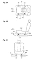
- Fig. 3C is a frontal view illustrating an installed state of a load detecting part of a vehicle passenger detection apparatus according to the embodiment with respect to a seat.
- Figure 4 is a graph showing how a load detection signal differs when the number of load detecting part installed is different.
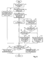
- Fig. 5 is a flowchart of a passenger detection process executed by the vehicle passenger detection apparatus according to the embodiment.
- Fig. 6 is a time chart showing characteristic plots of a vibration change amount, a load change amount, a detected load (four-point sensor), and a detected load (two-point sensor) obtained when a vehicle is moving with an adult passenger.
- Fig. 7 is a time chart showing characteristic plots of a vibration change amount, a load change amount, a detected load (four-point sensor), and a detected load (two-point sensor) obtained when a vehicle is stopped with an adult passenger.
- Fig. 1 is schematic plan view of a vehicle equipped with a vehicle passenger detection apparatus according to one embodiment.
- Fig. 2 is a block diagram of an air bag system having a vehicle passenger detection apparatus according to the embodiment.
- the air bag system 3 comprises an air bag 4, a passenger condition indicator lamp 5, a warning lamp 6, an air bag ECU 7, and a vehicle passenger detection apparatus 10.
- the air bag 4 is stored frontward of one of the seats 2 (a passenger seat 2a in this embodiment) inside an instrument panel 8 arranged in a frontward portion of a vehicle cabin.
- the air bag 4 serves to protect a passenger during a vehicle collision by deploying and exhibiting an impact absorbing function.
- a deployment size of the air bag 4 can be varied to at least two different sizes in accordance with a deployment signal from the air bag ECU 7.
- the passenger condition indicator lamp 5 is installed in the instrument panel 8 arranged in a frontward portion of the vehicle cabin and indicates a passenger condition detection result for the passenger seat 2a in accordance with an indication signal from the air bag ECU 7. Examples of passenger conditions include no passenger, seated adult, and child seat.
- the warning lamp 6 is installed in the instrument panel 8 arranged in a frontward portion of the vehicle cabin and illuminates as a warning indication in response to a failure signal issued from the air bag ECU 7 when a failure has been detected in the air bag system.
- the air bag ECU 7 has an internal CPU 7a and serves to execute a deployment determination with respect to the air bag 4 based on seat information obtained from the vehicle passenger detection apparatus 10 and to issue a deployment signal to the air bag 4.
- the deployment determination includes such determination results as not to deploy the air bag 4 when a passenger is not sitting in the passenger seat 2a, to deploy the air bag 4 when an adult is sitting in the passenger seat 2a, and not to deploy the air bag 4 when a child seat is being used to seat a child in the passenger seat 2a.
- the air bag ECU 7 also issues an indication signal to the passenger condition indicator lamp 5 based on seat information obtained from the vehicle passenger detection apparatus 10 and issues a failure signal to the warning lamp 6 when a failure is detected in the air bag system.
- the vehicle passenger detection apparatus 10 comprises a plurality of load sensors (load detecting means) 11 and a passenger detection ECU (seat condition determining part) 12 and serves to determine a state of the seat 2 (the passenger seat 2a in this explanation) and send seat information to the air bag ECU 7.
- the load sensors 11 are attached to a periphery of the passenger seat 2a (one of the seats 2) and detect loads acting on the passenger seat 2a.
- each of the seats 2 (including the passenger seat 2a) is attached to a vehicle body 21 through a left-right pair of slide rails 22 and 23 such that the seat can slide (position can be adjusted) in a longitudinal direction 24 of the vehicle along the slide rails 22 and 23.
- the seat 2 is supported at a total of four locations with respect to the pair of slide rails 22 and 23, i.e., at front and rear support points 24a to 24d on each of the left and right sides.
- a load sensor 11 is installed with respect to at least one of the support points 24a to 24d and not installed with respect to at least one of the support points 24a to 24d.
- at least one of the support points 24a to 24d does not have a load sensor 11 installed, thus establishing a load detecting part omitted section.
- a total of two load sensors 11 are provided, i.e., a load sensor 11 a is installed with respect to the front support point 24a and a load sensor 11b is installed with respect the rear support point 24b of the slide rail 22, which is the slide rail located more toward an inward side of the vehicle body 21.
- the two support points 24c and 24d where the seat is supported on the slide rail 23 located more toward an outward side the vehicle body 21 are load detecting part omitted sections.
- Figure 4 is a graph showing how a load detection signal differs when the number of load detecting part installed is different.
- the curve e illustrates a total sum of the load detection signals in a case according to the illustrated embodiment in which two load sensors 11 are provided such that one is located at the frontward support point 24a and one is located at the rearward support point 24b
- the curve f illustrates a total sum of the load detection signals for a case in which a load sensor 11 is provided at each of all four support points 24a to 24d.
- the magnitude of the total load detection signal for a case in which load sensors 11 are provided in two locations is approximately one-half the size of the magnitude of the total load detection signal for a case in which load sensors 11 are provided at all four of the support points 24a to 24d when the vehicle is traveling on a straight path, as indicated by the curve e and the curve f .
- the magnitude of the total load detection signal decreases greatly in comparison with traveling on a straight path. This phenomenon is believed to be caused by a centrifugal force acting on the side opposite the side where the load sensors 11 are provided and causing the detected load to decrease.
- load sensors 11 arranged at a combination of two support points among the support points 24a to 24d other than the combination already explained, i.e., at the front and rear support points 24c and 24d of the slide rail 23 located toward the outward side of the vehicle body 21, at the front support points 24a and 24c, at the rear support points 24b and 24d, or at the diagonally positioned support points 24a and 24d or 24c and 24b. It is also acceptable to provide load sensors 11 in three locations and leave only one of front and rear support points 24a to 24d without. Furthermore, it is acceptable to provide a load sensor 11 at only one of the front and rear support points 24a to 24d. However, since, as previously explained, the magnitude and stability of the total load detection signal degrade as the number of load sensors 11 installed is decreased, it is preferable to install load sensors 11 in two or three locations instead of one.
- the passenger detection ECU 12 has a CPU 12a and serves to determine a sitting condition of the seat 2 based on load detection signals from the load sensors 11.
- the CPU 12a has a signal converting section 13, a vibration waveform removing section 14 (vibration waveform removing means), a load change amount determination logic (vibration threshold value setting section) 15, a vibration change amount determination logic (vibration determining section) 16, and a seat determining section 17.
- the signal converting section 13 converts the analog load detection signals outputted from the load sensors 11a and 11b into digital signals.
- a separate signal converting section 13 is provided with respect to each of the load sensors 11a and 11b installed on the passenger seat 2a and indicated as "A/D" in Fig. 2 .
- the vibration waveform removing section 14 removes a vibration waveform indicating that a vibration is occurring from a load detection signal converted to digital by the signal converting section 13 and generates a vibration waveform removed signal.
- the "vibration waveform" is, for example, a high frequency vibration component (travel vibration) oriented in a vertical direction.
- the vibration waveform removing section 14 uses a low pass filter that can remove such vibration waveforms as, for example, a high frequency vibration component.
- a separate vibration waveform removing section 14 is provided with respect to each of the signal converting sections 13 and indicated as "LPF" in Fig. 2 .
- the load change amount determination logic 15 sets a vibration threshold value based on the vibration waveform removed signal, i.e., the load detection signal resulting after the vibration waveform removing section 14 has removed the vibration waveform from the load detection signal.
- the threshold value is a value that will serve as a reference when determining if a vehicle vibration is occurring.
- the load change amount determination logic 15 sets the vibration threshold value to a higher value when the fluctuation amount of the vibration waveform removed signal is small than when the fluctuation amount of the vibration waveform removed signal is large.
- the vibration threshold value is set to a higher value than when the fluctuation amount of the vibration waveform removed signal is large.
- a sum of the vibration waveform removed signals is calculated and an absolute value of a fluctuation amount of this sum is calculated as a load fluctuation amount.
- the load fluctuation amount is then compared to a weight threshold value already prepared in the load change amount determination logic 15. If a state in which the load fluctuation amount is equal to or smaller than the weight threshold value continues for a prescribed amount of time, then the load acting on the passenger seat 2a is stable, i.e., the outputted weight information is stable, and the vibration threshold value is set to a higher value. Meanwhile, if the load fluctuation amount exceeds the weight threshold value, then the load acting on the passenger seat 2a is unstable, i.e., the outputted weight information is unstable, and the vibration threshold value is set to a low value.
- the vibration change amount determination logic 16 determines if a vehicle vibration is occurring based on the load detection signal digitized by the signal converting section 13 and the vibration threshold value set by the load change amount determination logic 15.
- the "load detection signal digitized by the signal converting section 13" is the digital load detection signal as it exists before the vibration waveform is removed by the vibration waveform removing section 14 and, thus, still includes the vibration waveform. How a determination is made as to whether a vehicle vibration is occurring will now be explained.
- An absolute value of a fluctuation amount of each of the load detection signals from the load sensors 11a and 11b is calculated.
- a total sum of the absolute values of the fluctuation amounts is calculated as a vibration change amount and the vibration change amount is compared to the vibration threshold value set by the load change amount determination logic 15. If the vibration change amount is equal to or larger than the vibration threshold value, then it is determined that a vehicle vibration is occurring. If the vibration change amount is smaller than the vibration threshold value, then it is determined that a vehicle vibration is not occurring.
- the seat determining section 17 executes a seating determination based on a load detection signal or defers the seating determination in accordance with the size of a vehicle vibration.
- the seat determining section 17 has a passenger determination logic 17a and a passenger determination logic 17b.
- the passenger determination logic 17a executes a seating determination based on the vibration waveform removed signal, i.e., the load detection signal resulting after the vibration waveform removing section 14 has removed the vibration waveform from the load detection signal.
- the "seating determination” mentioned here means to execute a seated passenger determination to determine if a passenger is sitting on the passenger seat 2a and a body type determination to determine if a passenger sitting on the passenger seat 2a has a large body type (e.g., if a seated passenger is an adult or a child using a child seat). It is also acceptable to execute one or the other of these determinations.
- the seating determination involves finding a detected load as a total sum of vibration waveform removed signals and comparing the detected load to a first threshold value, a second threshold value, and a third threshold value already provided in the passenger determination logic 17a. The logic then determines that an adult is sitting if the detected load is equal to or larger than the first threshold value, that a child is sitting using a child seat if the detected load is equal to or larger than the second threshold value but smaller than the first threshold value, and that the seat is empty if the detected load is equal to or larger than the third threshold value but smaller than the second threshold value.
- the passenger determination logic 17b determines if the seat information should be updated based on a determination result from the vibration change amount determination logic 16 and sets the obtained seat information to the air bag ECU 7. That is, if the vibration change amount determination logic 16 has determined that a vehicle vibration is not occurring, then the passenger determination logic 17b treats the seating determination result from the passenger determination logic 17a as new seat information and updates the seat information. Meanwhile, if the vibration change amount determination logic 16 has determined that a vehicle vibration is occurring, then the passenger determination logic 17b does not treat the seating determination result from the passenger determination logic 17a as new seat information and maintains the seat information from the previous control cycle.
- the seat determining section 17 executes a seating determination when it has determined that a vehicle vibration is not occurring and maintains the seating determination result of the previous cycle by deferring execution of a seating determination when it has determined that a vehicle vibration is occurring.
- Fig. 5 is a flowchart of a passenger detection process executed by the vehicle passenger detection apparatus according to the illustrated embodiment. The steps of Fig. 5 will now be explained.
- step S1 the apparatus reads load detection signals (Sen1(t), Sen2(t)) constituting weight information from each of the load sensors 11a and 11b installed on a seat (the passenger seat 2a in this explanation) and proceeds to step S2 and step S5.
- load detection signals Sen1(t), Sen2(t)
- step S2 After reading the load detection signals in step S 1, in step S2 the apparatus removes a vibration waveform constituting a high frequency vibration component from each of the load detection signals and obtains vibration waveform removed signals (LPF_Sen1(t), LPF_Sen2(t)) corresponding to the load sensors 11a and 11b The apparatus then proceeds to step S3.
- the removal of the vibration waveform is accomplished by executing a low pass filter process.
- step S3 the apparatus calculates a detected load W by calculating a sum of the vibration waveform removed signals obtained by removing the vibration waveforms. The apparatus then proceeds to steps S4 and S6.
- the detected load W is calculated using the equation (1) shown below.
- step S4 After calculating the detected load W in step S3, in step S4 the apparatus executes a seating determination and proceeds to step S 11.
- This seating determination involves comparing the detected weight W to a first threshold value TH/L ⁇ 1, a second threshold value TH/L ⁇ 2, and a third threshold value TH/L ⁇ 3 already provided in the passenger determination logic 17a and finding a seating determination result according to the equations (2) to (4) below.
- Th / L ⁇ ⁇ 1 > W ⁇ TH / L ⁇ ⁇ 2 child seated in a child seat
- step S5 After reading the load detection signals in step S1, in step S5 the apparatus finds an absolute value of a fluctuation amount ( ⁇ Sen1, ⁇ Sen2) of each of the load detection signals and calculates a sum ⁇ Sum of the absolute values of the fluctuation amounts.
- the fluctuation amounts correspond to vibration waveforms and the sum is a vibration change amount. The apparatus then proceeds to step S 11.
- the absolute values ( ⁇ Sen1 and ⁇ Sen2) of the fluctuation amounts of the load detection signals are calculated using the equations (5) and (6) show below, and the vibration change amount ⁇ Sum equal to the sum of the absolute values of the fluctuation amounts is calculated using the equation (7).
- the reason absolute values are used is to prevent the vibration waveforms detected by the load sensors 11a and 11b from cancelling each other out and to emphasize the vibration waveform.
- ⁇ Sum abs ⁇ Sen ⁇ 1 t - Sen ⁇ 1 ⁇ t - 1 + abs ⁇ Sen ⁇ 2 t - Sen ⁇ 2 ⁇ t - 1
- step S6 the apparatus calculates a load fluctuation amount ⁇ W by finding the absolute value of a fluctuation amount of the detected load W and proceeds to step S7.
- the absolute value (load fluctuation amount) ⁇ W of the detected weight W is calculated using the equation (8) shown below.
- step S7 the apparatus determines if the load fluctuation amount ⁇ W is equal to or smaller than a weight threshold value TH/L ⁇ already provided in the load change amount determination logic 15. If the determination result is Yes ( ⁇ W ⁇ LH/L ⁇ ), then a load fluctuation has not occurred, i.e., the weight information output is stable, and the apparatus proceeds to step S8. If the determination result is No ( ⁇ W > TH/L ⁇ ), then a load fluctuation has occurred, i.e., the weight information is unstable, and the apparatus proceeds to step S 10.
- step S8 the apparatus determines if a prescribed amount of time (e.g., 3 seconds) has elapsed. If Yes (the prescribed amount of time has elapsed), then the weight information is stable and the apparatus proceeds to step S9. If No (the prescribed amount of time has not elapse), then a load fluctuation is occurring, i.e., the weight information is unstable, and the apparatus proceeds to step S10.
- a prescribed amount of time e.g. 3 seconds
- step S9 the apparatus sets the vibration threshold value to a high value (TH/L ⁇ High) and proceeds to step S11.
- step S10 After determining that the weight information is unstable in step S7 or step S8, in step S10 the apparatus sets the vibration threshold value to a low value (TH/L ⁇ Low) and proceeds to step S11. What is considered a high value and a low value for the vibration threshold value is relative. So long as the relationship TH/L ⁇ High > TH/L ⁇ Low is maintained, any values can be set as the threshold values.
- step S4 After the seating determination has been executed in step S4, the vibration change amount ⁇ Sum has been calculated in step S5, the vibration threshold value has been set (TH/L ⁇ High or TH/L ⁇ Low) in step S9 or step S 10, the apparatus proceeds to step S11 and determines if the vibration change amount ⁇ Sum is equal to or larger than the vibration threshold value (TH/L ⁇ High or TH/L ⁇ Low). If Yes ( ⁇ Sum ⁇ TH/L ⁇ High or TH/L ⁇ Low), then the apparatus proceeds to step S12. If No ( ⁇ Sum ⁇ TH/L ⁇ High or TH/L ⁇ Low), then the apparatus proceeds to step S 13.
- step S12 After determining that the vibration change amount ⁇ Sum is equal to or larger than the vibration threshold value (TH/L ⁇ High or TH/L ⁇ Low) in step S 11, in step S12 the apparatus deems that a vehicle vibration is occurring and maintains the seat information of the previous control cycle without treating the seating determination result obtained in step S4 as new seat information. Thus, the apparatus outputs the same seat information as in the previous cycle.
- the vibration threshold value TH/L ⁇ High or TH/L ⁇ Low
- step S 13 After determining that the vibration change amount ⁇ Sum is smaller than the vibration threshold value (TH/L ⁇ High or TH/L ⁇ Low) in step S 11, in step S 13 the apparatus deems that a vehicle vibration is not occurring and updates the seat information by treating the seating determination result obtained in step S4 as new seat information. Thus, the apparatus outputs the new seat information obtained in step S4.
- Fig. 6 is a time chart showing characteristic plots of a vibration change amount, a load change amount, a detected load (four-point sensor), and a detected load (two-point sensor) obtained when a vehicle is moving with an adult passenger.
- Fig. 7 is a time chart showing characteristic plots of a vibration change amount, a load change amount, a detected load (four-point sensor), and a detected load (two-point sensor) obtained when a vehicle is stopped with an adult passenger.
- a vibration threshold value is set in advance with respect to a vibration change amount calculated as the sum of absolute values of fluctuation amounts of a plurality of load detection signals.
- the vehicle vibration is determined to be large if the vibration change amount is equal to or larger than the vibration threshold value, and the vehicle vibration is determined to be small if the vibration change amount is smaller than the vibration threshold value.
- Fig. 6 illustrates the characteristic curves for a vehicle that is moving while carrying an adult passenger (a 49-kg woman).
- the vibration change amount is above the vibration threshold value TH/L ⁇ Low. Therefore, the seating determination is deferred and the determination result from the previous control cycle is maintained.
- the vibration change amount intermittently falls below the vibration threshold value TH/L ⁇ Low. vibration change amount does not stay below the vibration threshold value TH/L ⁇ Low continuously. Then, after the time t4, the vibration change amount completely exceeds the vibration threshold value TH/L ⁇ Low and the seating determination cannot be executed.
- the seating determination is deferred and an updated determination result cannot be obtained.
- the vibration change amount is comparatively large while the vehicle is moving, then the seating determination is deferred and an updated determination result cannot be obtained.
- the vibration change amount is comparatively large while the vehicle is moving, then the seating determination will be deferred while the vehicle is moving and the vehicle vibration is comparatively large. Consequently, there is a possibility that the apparatus will maintain the determination result of the previous cycle without obtaining an appropriate seating determination.
- Fig. 7 illustrates the characteristic curves for a vehicle that is stopped while carrying an adult passenger (a 57-kg man).
- the vibration change amount is below the vibration threshold value TH/L ⁇ Low. Therefore, the seating determination is executed.
- the passenger starts shaking his body or knees and causes a vehicle vibration to occur.
- the vibration change amount during this period is higher than the vibration threshold value TH/L ⁇ Low and the seating determination is deferred.
- the vibration change amount is below the vibration threshold value TH/L ⁇ Low and the vibration determination is executed.
- the passenger switches sides of the crossed legs and causes a large vehicle vibration to occur.
- the vibration change amount during this period is higher than the vibration threshold value TH/L ⁇ Low and the seating determination is deferred.
- the vibration change amount is below the vibration threshold value TH/L ⁇ Low and the vibration determination is executed.
- the vibration threshold value TH/L ⁇ Low Since the difference between the vibration threshold value TH/L ⁇ Low and the vibration change amount is small, it is conceivable that there are times when the vibration change amount exceeds the vibration threshold value TH/L ⁇ Low depending on the way the passenger shakes. Afterwards, during a period from the time t6 to a time t8, the passenger switches sides of the crossed legs again and causes a large vehicle vibration to occur. The vibration change amount during this period is higher than the vibration threshold value TH/L ⁇ Low and the seating determination is deferred. During a period from the time t8 to a time t10, the vibration change amount temporarily falls below the vibration threshold value TH/L ⁇ Low and the seating determination is execute.
- the passenger's leg movement becomes rhythmical and a vehicle vibration occurs such that the vibration change amount exceeds the vibration threshold value TH/L ⁇ Low and the seating determination is deferred.
- the vibration threshold value is set to a higher value when a fluctuation amount of the load detection signal is small than when a fluctuation amount of the load detection signal is large. Consequently, as illustrated by the characteristic curves shown in Fig. 6 for a case in which an adult (49-kg woman) passenger is carried while the vehicle is moving, if the detected load is stable because the vehicle is traveling along a straight path, then at a time t1 the load change amount will fall below the weight threshold value TH/L ⁇ at a time t1. As a result, the apparatus will execute step S7 and step S8 of the flowchart shown in Fig. 5 .
- the apparatus proceeds from step S8 to step S9 and changes the vibration threshold value from the lower value TH/L ⁇ Low to the higher value TH/L ⁇ High.
- the vibration change amount is below the vibration threshold value TH/L ⁇ High and the seating determination is executed even if the vehicle is moving.
- the load change amount exceeds the weight threshold value TH/L ⁇ and the apparatus proceeds from step S7 to step S 10 of the flowchart shown in Fig 5 , thereby changing the vibration threshold value from the higher value TH/L ⁇ High to the lower value TH/L ⁇ Low.
- the vibration change amount exceeds the vibration threshold value TH/L ⁇ Low and the seating determination is deferred such that the previous determination result is maintained.
- the vehicle travels through a curve and a centrifugal force acting on the seat 2 causes the detected load, i.e., the sum of the load detection signals (vibration waveform removed signals in this embodiment) to decrease greatly in a case where the load detection signals are detected with two sensors.
- the load change amount output is comparatively stable.
- the load change amount falls below the weight threshold value TH/L ⁇
- a prescribed amount of time has elapsed with the load change amount continuously below the weight threshold value TH/L ⁇ . Consequently, at the time t6, the vibration threshold value is changed from TH/L ⁇ Low to TH/L ⁇ High.
- the load change amount exceeds the weight threshold value TH/L ⁇ again at a time t7. Consequently, the vibration threshold value does not remain at the value TH/L ⁇ High and is changed back to the value TH/L ⁇ Low such that the seating determination continues to be deferred.
- the seating determination can be executed even though the vehicle is moving by increasing the vibration threshold value. As a result, more opportunities to execute the seating determination can be obtained while the vehicle is moving.
- the vibration threshold value is set to the comparatively high value TH/L ⁇ High and, since the vibration change amount does not fall below this vibration threshold valve TH/L ⁇ High, the seating determination is executed during the period from the time t0 to the time t3.
- the passenger crosses his legs and the load change amount exceeds the weight threshold value TH/L ⁇ .
- the apparatus proceeds from step S7 to step S10 of the flowchart shown in Fig 5 , thereby changing the vibration threshold value from the higher value TH/L ⁇ High to the lower value TH/L ⁇ Low.
- the vibration change amount exceeds the vibration threshold value TH/L ⁇ Low and the seating determination is deferred such that the previous determination result is maintained.
- the load change amount falls below the weight threshold value TH/L ⁇
- a prescribed amount of time has elapsed with the load change amount continuously below the weight threshold value TH/L ⁇ .
- the vibration threshold value is changed from TH/L ⁇ Low to TH/L ⁇ High.
- the seating determination is executed because the vibration change amount does not exceed the vibration threshold value TH/L ⁇ High. Since the difference between the vibration threshold value TH/L ⁇ High and the vibration change amount is large, it is unlikely that the vibration change amount will exceed the vibration threshold value TH/L ⁇ High even if the passenger shakes somewhat strongly.
- the passenger switches sides of the crossed legs and the load change amount exceeds the weight threshold value TH/L ⁇ , causing the vibration threshold value to be changed from TH/L ⁇ High to TH/L ⁇ Low.
- the vibration change amount exceeds the vibration threshold value TH/L ⁇ Low and the seating determination is deferred.
- the passenger's leg movement becomes rhythmical and a vehicle vibration occurs, but the load change amount decreases and falls below the weight threshold value TH/L ⁇ at a time t9.
- a prescribed amount of time has elapsed with the load change amount continuously below the weight threshold value TH/L ⁇ . Therefore, the vibration threshold value is changed from TH/L ⁇ Low to TH/L ⁇ High. Since the vibration change amount is smaller than the vibration threshold value TH/L ⁇ High, the seating determination is executed.
- the vibration threshold value is set to a higher value when a fluctuation amount of the load detection signal is small than when a fluctuation amount of the load detection signal is large.
- the seating determination is less likely to be deferred when a posture or movement of a passenger causes a vehicle vibration to occur while the vehicle is stopped. As a result, more opportunities to execute the seating determination can be obtained when a passenger moves while the vehicle is stopped.
- the vibration threshold value is set to a higher value when a state in which the load change amount is below the weight threshold value TH/L ⁇ has continued for a prescribed amount of time. Consequently, the vibration threshold value does not easily change when the load change amount fluctuates for a short period of time due to road vibration or the like. As a result, the vibration threshold value used as a reference when determining if a vehicle vibration is occurring can be set in a more stable fashion.
- the vibration waveform removing section 14 generates the vibration waveform removed signal, i.e., a load detection signal with a vibration waveform removed, from the load detection signals.
- the load change amount determination logic 15 sets the vibration threshold values based on the vibration waveform removed signals.
- the vibration change amount determination logic 16 determines if a vehicle vibration is occurring based on a load detection signal that has been converted to digital by the signal converting section 13.
- the passenger determination logic 17a executes the seating determination based on the vibration waveform removed signal. Consequently, the load change amount determination logic 15 and the passenger determination logic 17a can set the threshold value accurately and execute an accurate seating determination without being affected by the vibration waveform.
- the vibration change amount determination logic 16 can also execute an accurate vibration determination by using a load detection signal that includes the vibration waveform. As a result, the precision of both the settings and the determinations can be improved.
- the seat 2 (passenger seat 2a) is supported with respect to the vehicle body 21 at a plurality of support points 24a to 24d and the load sensors 11, i.e., a total of two load sensors 11a and 11b, are provided at the two front and rear support points 24a and 24b located on the slide rail 22 located more toward the inward side of the vehicle body 21.
- the load sensors 11 i.e., a total of two load sensors 11a and 11b
- the vehicle passenger detection apparatus 10 comprises: load detecting part (load sensors) 11a and 11b that are installed in the vicinity of a seat (passenger seat) 2a and detect a load acting on the seat 2a; and a seat condition determining part (seat condition determining means) 12 (passenger detection ECU) that determines a condition of the seat 2a based on load detection signals from the load detecting part 11a and 11b
- the seat condition determining part 12 comprises: a vibration threshold value setting section (vibration threshold value setting means) 15 (load change amount determination logic) that sets a vibration threshold value based on the load detection signals to serve as a reference when determining if a vehicle vibration is occurring; a vibration determining section (vibration determining means) 16 (vibration change amount determination logic) that determines if a vehicle vibration is occurring based on the load detection signals and the vibration threshold value; and a seat determining section (seat determining means) 17 that executes a seating determination based on the load detection signals when the vibration determining section
- deferments of the seating determination can be decreased and opportunities for executing the seating determination can be increased when the size of a vehicle vibration is used to decide whether to execute or defer the seating determination.
- the vibration threshold value setting section (load change amount determination logic) 15 is configured to set the vibration threshold value to a higher value when a state in which the fluctuation amount of the load detection signal is small has continued for a prescribed amount of time than when the fluctuation amount of the load detection signal is large.
- the vibration threshold value serving as a reference for determining if a vehicle vibration is occurring can be set in a stable fashion even when the load change amount fluctuations for a short amount of time due to road vibration or the like.
- the seat condition determining part (passenger detection ECU) 12 is provided with a vibration waveform removing section 14 that removes a vibration waveform indicating that a vibration is occurring from the load detection signals.
- the vibration threshold value setting section (load change amount determination logic) 15 finds a vibration threshold value based on the vibration waveform removed signal obtained after the vibration waveform removing section 14 has removed the vibration waveform from the load detection signal, and the vibration determining section (vibration change amount determination logic) 16 determines if a vehicle vibration is occurring based on the load detection signals including the vibration waveform, i.e., the load detection signals as they exist before the vibration waveform has been removed by the vibration waveform removing section 14.
- the seat determining section 17 executes a seating determination based vibration waveform removed signals, i.e., the load detection signals resulting after the vibration waveform has been removed by the vibration waveform removing section 14.
- the threshold value can be set, the seating determination can be executed, and the vibration determination can be executed based on appropriate signals and the settings and determinations can be accomplished with improved precision.
- the seat (passenger seat) 2a is supported with respect to the vehicle body 21 at a plurality of support points 24a to 24d and a load detecting part (load sensor) 11 is installed with respect to at least one of the support points (support points 24a and 24b) and not installed with respect to at least one of the support points.
- a load detecting part (load sensor) 11 is installed with respect to at least one of the support points (support points 24a and 24b) and not installed with respect to at least one of the support points.
- the passenger determination logic 17a executes a seating determination regardless of the determination result obtained by the vibration change amount determination logic 16 and decides whether to update or to maintain the seat information based on the determination result obtained with the vibration change amount determination logic 16.
- the invention is not limited to such an approach. For example, it is also acceptable to execute or defer the seating determination based on the determination result obtained with the vibration change amount determination logic 16.
- the vibration change amount determination logic 16 determines that the vehicle vibration is large, the passenger determination logic 17a does not execute the seating determination. With this approach, number of computations executed by the passenger determination logic 17a can be reduced.
- the weight threshold value (TH/L ⁇ ) is a fixed value provided in the load change amount determination logic 15 in advance. However, it is acceptable to change the value in response the passenger who is sitting.
- the weight threshold value could be set to 1(N) when an adult is sitting and 0.5(N) when a child is sitting in a child seat. In this way, a more nuanced determination can be accomplished.
- the vibration threshold value is set to a higher value when a state in which the fluctuation amount of the vibration waveform removed signal is small has continued for a prescribed amount of time than when the fluctuation amount of the vibration waveform removed signal is large.
- the vibration threshold value is lowered immediately when the load detection signal falls below the weight threshold value and the vibration threshold value is raised immediately when the load detection signal is exceeds the weight threshold value.
Landscapes
- Engineering & Computer Science (AREA)
- Physics & Mathematics (AREA)
- Mathematical Physics (AREA)
- Theoretical Computer Science (AREA)
- General Physics & Mathematics (AREA)
- Mechanical Engineering (AREA)
- Aviation & Aerospace Engineering (AREA)
- Transportation (AREA)
- Seats For Vehicles (AREA)
Abstract
Description
- This application claims priority to Japanese Patent Application No.
2011-108331 filed on May 13, 2011 2011-108331 - The present invention relates to a vehicle passenger detection apparatus that is installed in an automobile or other vehicle and used to determine whether or not to activate an air bag device provided in the vehicle.
- Air bag systems that can protect a passenger seated in a seat have been provided in automobiles and other vehicles for some time. Such an air bag system has a vehicle passenger detection apparatus that determines if a passenger is seated in a seat or not and if a seated passenger is an adult or a child. The vehicle passenger detection apparatus has a load sensor installed on a set periphery and a seat condition determining part that executes a seating determination based on a detection signal from a load sensor (e.g., see Japanese Patent Number
4339368 - When a seating determination is executed or deferred depending on the size of a vehicle vibration, there are situations in which the precision of the seating determination may decline. For example, if a passenger boards the vehicle while it is stopped and does not sit fully and stably in the seat until after the vehicle is moving, then the precision of the seating determination will decline because the passenger did not have a stable posture when the vehicle was stopped and vehicle vibrations were comparatively small. Meanwhile, when the vehicle is moving and the passenger is seated in a stable fashion, the seating determination is deferred because the vehicle vibrations are comparatively large. Thus, in some cases, it is desirable to execute a seating determination while a vehicle is moving and vehicle vibrations are comparatively large.
- Even when the vehicle is stopped and vehicle vibrations are comparatively small, if a seating determination is executed according to the size of vehicle vibrations, then there is a possibility that a vehicle vibration caused by a condition of a passenger will be detected and cause the seating determination to be deferred.
- Therefore, an object of the present invention is to provide a vehicle passenger detection apparatus that can reduce deferments of a seating determination and increase opportunities for executing the seating determination when a size of a vehicle vibration is used to decide whether to execute or to defer a seating determination.
- In order to achieve the aforementioned object, a vehicle passenger detection apparatus according to one aspect of the present invention includes load detecting means and seat condition determining means. The load detecting means is installed in the vicinity of a seat of a vehicle to detect a load acting on the seat. The seat condition determining means is configured to determine a condition of the seat based on a load detection signal from the load detecting means. The seat condition determining means includes vibration threshold value setting means, vibration determining means and seat determining means. The vibration threshold value setting means is configured to set a vibration threshold value based on the load detection signal such that the vibration threshold value is higher when a fluctuation amount of the load detection signal is small than when the fluctuation amount of the load detection signal is large. The vibration determining means is configured to determine if the vehicle vibration is occurring based on the load detection signal and the vibration threshold value. The seat determining means is configured to execute a seating determination based on the load detection signal when the vibration determining means determines that the vehicle vibration is not occurring, and to defer execution of the seating determination to maintain a previous seating determination result when the vibration determining means determines that the vehicle vibration is occurring.
- With this aspect of the present invention, the vibration threshold value setting means sets the vibration threshold value to a higher value when a fluctuation amount of the load detection signal is small than when the fluctuation amount of the load detection signal is large. Thus, setting the vibration threshold value higher serves to decrease the likelihood that the vibration determining means (which determines whether or not a vehicle vibration is occurring) will determine that a vehicle vibration has occurred. In other words, when the fluctuation amount of the load detection signal is small, the vibration determining means is more likely to determine that the vehicle vibration is not occurring than when the fluctuation amount of the load detection signal is large.
- As a result, for example, when a passenger's posture causes a vibration to occur while the vehicle is moving or stopped, if the fluctuation amount of the load detection signal is small and the load detection signal is stable, then the vibration threshold value is set high and the apparatus will be more likely to determine that a vehicle vibration is not occurring. If it is determined that a vehicle vibration is not occurring, then the seat determining means executes a seating determination and the opportunities for executing a determination can be increased.
- As a result, deferments of the seating determination can be decreased and opportunities for executing the seating determination can be increased when the size of a vehicle vibration is used to decide whether to execute or defer the seating determination.
- Referring now to the attached drawings which form a part of this original disclosure:
-
Fig. 1 is schematic plan view of a vehicle equipped with a vehicle passenger detection apparatus according to an embodiment. -
Fig. 2 is a block diagram of an air bag system having a vehicle passenger detection apparatus according to the embodiment. -
Fig. 3A is a plan view,Fig. 3B is a side view, andFig. 3C is a frontal view illustrating an installed state of a load detecting part of a vehicle passenger detection apparatus according to the embodiment with respect to a seat. -
Figure 4 is a graph showing how a load detection signal differs when the number of load detecting part installed is different. -
Fig. 5 is a flowchart of a passenger detection process executed by the vehicle passenger detection apparatus according to the embodiment. -
Fig. 6 is a time chart showing characteristic plots of a vibration change amount, a load change amount, a detected load (four-point sensor), and a detected load (two-point sensor) obtained when a vehicle is moving with an adult passenger. -
Fig. 7 is a time chart showing characteristic plots of a vibration change amount, a load change amount, a detected load (four-point sensor), and a detected load (two-point sensor) obtained when a vehicle is stopped with an adult passenger. - Selected embodiments will now be explained with reference to the drawings. It will be apparent to those skilled in the art from this disclosure that the following descriptions of the embodiments are provided for illustration only and not for the purpose of limiting the invention as defined by the appended claims and their equivalents.
-
Fig. 1 is schematic plan view of a vehicle equipped with a vehicle passenger detection apparatus according to one embodiment.Fig. 2 is a block diagram of an air bag system having a vehicle passenger detection apparatus according to the embodiment. - As shown in
Fig. 1 , a plurality ofseats 2 for passengers to sit on and anair bag system 3 that can protect a passenger seated on aseat 2 are installed in a vehicle 1 (automobile or the like). As shown inFig. 2 , theair bag system 3 comprises anair bag 4, a passengercondition indicator lamp 5, awarning lamp 6, an air bag ECU 7, and a vehiclepassenger detection apparatus 10. - The
air bag 4 is stored frontward of one of the seats 2 (apassenger seat 2a in this embodiment) inside aninstrument panel 8 arranged in a frontward portion of a vehicle cabin. Theair bag 4 serves to protect a passenger during a vehicle collision by deploying and exhibiting an impact absorbing function. A deployment size of theair bag 4 can be varied to at least two different sizes in accordance with a deployment signal from the air bag ECU 7. - The passenger
condition indicator lamp 5 is installed in theinstrument panel 8 arranged in a frontward portion of the vehicle cabin and indicates a passenger condition detection result for thepassenger seat 2a in accordance with an indication signal from the air bag ECU 7. Examples of passenger conditions include no passenger, seated adult, and child seat. - The
warning lamp 6 is installed in theinstrument panel 8 arranged in a frontward portion of the vehicle cabin and illuminates as a warning indication in response to a failure signal issued from the air bag ECU 7 when a failure has been detected in the air bag system. - The air bag ECU 7 has an
internal CPU 7a and serves to execute a deployment determination with respect to theair bag 4 based on seat information obtained from the vehiclepassenger detection apparatus 10 and to issue a deployment signal to theair bag 4. The deployment determination includes such determination results as not to deploy theair bag 4 when a passenger is not sitting in thepassenger seat 2a, to deploy theair bag 4 when an adult is sitting in thepassenger seat 2a, and not to deploy theair bag 4 when a child seat is being used to seat a child in thepassenger seat 2a. The air bag ECU 7 also issues an indication signal to the passengercondition indicator lamp 5 based on seat information obtained from the vehiclepassenger detection apparatus 10 and issues a failure signal to thewarning lamp 6 when a failure is detected in the air bag system. - The vehicle
passenger detection apparatus 10 comprises a plurality of load sensors (load detecting means) 11 and a passenger detection ECU (seat condition determining part) 12 and serves to determine a state of the seat 2 (thepassenger seat 2a in this explanation) and send seat information to the air bag ECU 7. - The
load sensors 11 are attached to a periphery of thepassenger seat 2a (one of the seats 2) and detect loads acting on thepassenger seat 2a. As shown inFigs. 3A to 3C , each of the seats 2 (including thepassenger seat 2a) is attached to avehicle body 21 through a left-right pair ofslide rails longitudinal direction 24 of the vehicle along theslide rails seat 2 is supported at a total of four locations with respect to the pair ofslide rails rear support points 24a to 24d on each of the left and right sides. - Thus, if the
seat 2 is supported with respect-to thevehicle body 21 at a plurality ofsupport points 24a to 24d, then aload sensor 11 is installed with respect to at least one of thesupport points 24a to 24d and not installed with respect to at least one of thesupport points 24a to 24d. In other words, at least one of the support points 24a to 24d does not have aload sensor 11 installed, thus establishing a load detecting part omitted section. - In the illustrated embodiment, a total of two
load sensors 11 are provided, i.e., aload sensor 11 a is installed with respect to thefront support point 24a and aload sensor 11b is installed with respect therear support point 24b of theslide rail 22, which is the slide rail located more toward an inward side of thevehicle body 21. - Thus, the two
support points slide rail 23 located more toward an outward side thevehicle body 21 are load detecting part omitted sections. -
Figure 4 is a graph showing how a load detection signal differs when the number of load detecting part installed is different. InFig. 4 , the curve e illustrates a total sum of the load detection signals in a case according to the illustrated embodiment in which twoload sensors 11 are provided such that one is located at thefrontward support point 24a and one is located at therearward support point 24b, and the curve f illustrates a total sum of the load detection signals for a case in which aload sensor 11 is provided at each of all foursupport points 24a to 24d. - The magnitude of the total load detection signal for a case in which load
sensors 11 are provided in two locations is approximately one-half the size of the magnitude of the total load detection signal for a case in which loadsensors 11 are provided at all four of the support points 24a to 24d when the vehicle is traveling on a straight path, as indicated by the curve e and the curve f. When the vehicle travels through a curve, the magnitude of the total load detection signal decreases greatly in comparison with traveling on a straight path. This phenomenon is believed to be caused by a centrifugal force acting on the side opposite the side where theload sensors 11 are provided and causing the detected load to decrease. - Conversely, when
load sensors 11 are installed at all of the support points 24a to 24d, as indicated by the curve f, the magnitude of the total load detection signal is stable regardless of whether the vehicle travels on a straight path or through a curve. This stability is believed to occur because a balance is achieved when the outputs of theload sensors 11 are summed together even if a centrifugal force exists. - It is also acceptable to provide
load sensors 11 arranged at a combination of two support points among the support points 24a to 24d other than the combination already explained, i.e., at the front and rear support points 24c and 24d of theslide rail 23 located toward the outward side of thevehicle body 21, at thefront support points support points load sensors 11 in three locations and leave only one of front and rear support points 24a to 24d without. Furthermore, it is acceptable to provide aload sensor 11 at only one of the front and rear support points 24a to 24d. However, since, as previously explained, the magnitude and stability of the total load detection signal degrade as the number ofload sensors 11 installed is decreased, it is preferable to installload sensors 11 in two or three locations instead of one. - The
passenger detection ECU 12 has aCPU 12a and serves to determine a sitting condition of theseat 2 based on load detection signals from theload sensors 11. TheCPU 12a has asignal converting section 13, a vibration waveform removing section 14 (vibration waveform removing means), a load change amount determination logic (vibration threshold value setting section) 15, a vibration change amount determination logic (vibration determining section) 16, and aseat determining section 17. - The
signal converting section 13 converts the analog load detection signals outputted from theload sensors signal converting section 13 is provided with respect to each of theload sensors passenger seat 2a and indicated as "A/D" inFig. 2 . - The vibration
waveform removing section 14 removes a vibration waveform indicating that a vibration is occurring from a load detection signal converted to digital by thesignal converting section 13 and generates a vibration waveform removed signal. The "vibration waveform" is, for example, a high frequency vibration component (travel vibration) oriented in a vertical direction. The vibrationwaveform removing section 14 uses a low pass filter that can remove such vibration waveforms as, for example, a high frequency vibration component. A separate vibrationwaveform removing section 14 is provided with respect to each of thesignal converting sections 13 and indicated as "LPF" inFig. 2 . - The load change
amount determination logic 15 sets a vibration threshold value based on the vibration waveform removed signal, i.e., the load detection signal resulting after the vibrationwaveform removing section 14 has removed the vibration waveform from the load detection signal. The threshold value is a value that will serve as a reference when determining if a vehicle vibration is occurring. The load changeamount determination logic 15 sets the vibration threshold value to a higher value when the fluctuation amount of the vibration waveform removed signal is small than when the fluctuation amount of the vibration waveform removed signal is large. More particularly, in the illustrated embodiment, when a state in which the fluctuation amount of the vibration waveform removed signal is small has continued for a prescribed amount of time, the vibration threshold value is set to a higher value than when the fluctuation amount of the vibration waveform removed signal is large. - How the vibration threshold value is set will now be explained. A sum of the vibration waveform removed signals is calculated and an absolute value of a fluctuation amount of this sum is calculated as a load fluctuation amount. The load fluctuation amount is then compared to a weight threshold value already prepared in the load change
amount determination logic 15. If a state in which the load fluctuation amount is equal to or smaller than the weight threshold value continues for a prescribed amount of time, then the load acting on thepassenger seat 2a is stable, i.e., the outputted weight information is stable, and the vibration threshold value is set to a higher value. Meanwhile, if the load fluctuation amount exceeds the weight threshold value, then the load acting on thepassenger seat 2a is unstable, i.e., the outputted weight information is unstable, and the vibration threshold value is set to a low value. - The vibration change
amount determination logic 16 determines if a vehicle vibration is occurring based on the load detection signal digitized by thesignal converting section 13 and the vibration threshold value set by the load changeamount determination logic 15. The "load detection signal digitized by thesignal converting section 13" is the digital load detection signal as it exists before the vibration waveform is removed by the vibrationwaveform removing section 14 and, thus, still includes the vibration waveform. How a determination is made as to whether a vehicle vibration is occurring will now be explained. An absolute value of a fluctuation amount of each of the load detection signals from theload sensors amount determination logic 15. If the vibration change amount is equal to or larger than the vibration threshold value, then it is determined that a vehicle vibration is occurring. If the vibration change amount is smaller than the vibration threshold value, then it is determined that a vehicle vibration is not occurring. - The
seat determining section 17 executes a seating determination based on a load detection signal or defers the seating determination in accordance with the size of a vehicle vibration. Theseat determining section 17 has apassenger determination logic 17a and apassenger determination logic 17b. - The
passenger determination logic 17a executes a seating determination based on the vibration waveform removed signal, i.e., the load detection signal resulting after the vibrationwaveform removing section 14 has removed the vibration waveform from the load detection signal. The "seating determination" mentioned here means to execute a seated passenger determination to determine if a passenger is sitting on thepassenger seat 2a and a body type determination to determine if a passenger sitting on thepassenger seat 2a has a large body type (e.g., if a seated passenger is an adult or a child using a child seat). It is also acceptable to execute one or the other of these determinations. More specifically, the seating determination involves finding a detected load as a total sum of vibration waveform removed signals and comparing the detected load to a first threshold value, a second threshold value, and a third threshold value already provided in thepassenger determination logic 17a. The logic then determines that an adult is sitting if the detected load is equal to or larger than the first threshold value, that a child is sitting using a child seat if the detected load is equal to or larger than the second threshold value but smaller than the first threshold value, and that the seat is empty if the detected load is equal to or larger than the third threshold value but smaller than the second threshold value. - The
passenger determination logic 17b determines if the seat information should be updated based on a determination result from the vibration changeamount determination logic 16 and sets the obtained seat information to the air bag ECU 7. That is, if the vibration changeamount determination logic 16 has determined that a vehicle vibration is not occurring, then thepassenger determination logic 17b treats the seating determination result from thepassenger determination logic 17a as new seat information and updates the seat information. Meanwhile, if the vibration changeamount determination logic 16 has determined that a vehicle vibration is occurring, then thepassenger determination logic 17b does not treat the seating determination result from thepassenger determination logic 17a as new seat information and maintains the seat information from the previous control cycle. - In this way, the
seat determining section 17 executes a seating determination when it has determined that a vehicle vibration is not occurring and maintains the seating determination result of the previous cycle by deferring execution of a seating determination when it has determined that a vehicle vibration is occurring. -
Fig. 5 is a flowchart of a passenger detection process executed by the vehicle passenger detection apparatus according to the illustrated embodiment. The steps ofFig. 5 will now be explained. - In step S1, the apparatus reads load detection signals (Sen1(t), Sen2(t)) constituting weight information from each of the
load sensors passenger seat 2a in this explanation) and proceeds to step S2 and step S5. - After reading the load detection signals in
step S 1, in step S2 the apparatus removes a vibration waveform constituting a high frequency vibration component from each of the load detection signals and obtains vibration waveform removed signals (LPF_Sen1(t), LPF_Sen2(t)) corresponding to theload sensors - After removing the vibration waveform in step S2, in step S3 the apparatus calculates a detected load W by calculating a sum of the vibration waveform removed signals obtained by removing the vibration waveforms. The apparatus then proceeds to steps S4 and S6.
- The detected load W is calculated using the equation (1) shown below.
-

- After calculating the detected load W in step S3, in step S4 the apparatus executes a seating determination and proceeds to step
S 11. - This seating determination involves comparing the detected weight W to a first threshold value TH/Lα1, a second threshold value TH/Lα2, and a third threshold value TH/Lα3 already provided in the
passenger determination logic 17a and finding a seating determination result according to the equations (2) to (4) below. -

-

-

- After reading the load detection signals in step S1, in step S5 the apparatus finds an absolute value of a fluctuation amount (ΔSen1, ΔSen2) of each of the load detection signals and calculates a sum ΔSum of the absolute values of the fluctuation amounts. The fluctuation amounts correspond to vibration waveforms and the sum is a vibration change amount. The apparatus then proceeds to step
S 11. - The absolute values (ΔSen1 and ΔSen2) of the fluctuation amounts of the load detection signals are calculated using the equations (5) and (6) show below, and the vibration change amount ΔSum equal to the sum of the absolute values of the fluctuation amounts is calculated using the equation (7). The reason absolute values are used is to prevent the vibration waveforms detected by the
load sensors -

-

-

- After calculating the detected load W in step S3, in step S6 the apparatus calculates a load fluctuation amount ΔW by finding the absolute value of a fluctuation amount of the detected load W and proceeds to step S7.
- The absolute value (load fluctuation amount) ΔW of the detected weight W is calculated using the equation (8) shown below.
-

- After calculating the load fluctuation amount ΔW in step S6, in step S7 the apparatus determines if the load fluctuation amount ΔW is equal to or smaller than a weight threshold value TH/Lβ already provided in the load change
amount determination logic 15. If the determination result is Yes (ΔW ≤ LH/Lβ), then a load fluctuation has not occurred, i.e., the weight information output is stable, and the apparatus proceeds to step S8. If the determination result is No (ΔW > TH/Lβ), then a load fluctuation has occurred, i.e., the weight information is unstable, and the apparatus proceeds to stepS 10. - After determining that a load fluctuation has not occurred in step S7, in step S8 the apparatus determines if a prescribed amount of time (e.g., 3 seconds) has elapsed. If Yes (the prescribed amount of time has elapsed), then the weight information is stable and the apparatus proceeds to step S9. If No (the prescribed amount of time has not elapse), then a load fluctuation is occurring, i.e., the weight information is unstable, and the apparatus proceeds to step S10.
- After determining that the weight information is stable in step S8, in step S9 the apparatus sets the vibration threshold value to a high value (TH/LαHigh) and proceeds to step S11.
- After determining that the weight information is unstable in step S7 or step S8, in step S10 the apparatus sets the vibration threshold value to a low value (TH/LαLow) and proceeds to step S11. What is considered a high value and a low value for the vibration threshold value is relative. So long as the relationship TH/LαHigh > TH/LαLow is maintained, any values can be set as the threshold values.
- After the seating determination has been executed in step S4, the vibration change amount ΔSum has been calculated in step S5, the vibration threshold value has been set (TH/LαHigh or TH/LαLow) in step S9 or step
S 10, the apparatus proceeds to step S11 and determines if the vibration change amount ΔSum is equal to or larger than the vibration threshold value (TH/LαHigh or TH/LαLow). If Yes (ΔSum ≥ TH/LαHigh or TH/LαLow), then the apparatus proceeds to step S12. If No (ΔSum < TH/LαHigh or TH/LαLow), then the apparatus proceeds to stepS 13. - After determining that the vibration change amount ΔSum is equal to or larger than the vibration threshold value (TH/LαHigh or TH/LαLow) in
step S 11, in step S12 the apparatus deems that a vehicle vibration is occurring and maintains the seat information of the previous control cycle without treating the seating determination result obtained in step S4 as new seat information. Thus, the apparatus outputs the same seat information as in the previous cycle. - After determining that the vibration change amount ΔSum is smaller than the vibration threshold value (TH/LαHigh or TH/LαLow) in
step S 11, in step S 13 the apparatus deems that a vehicle vibration is not occurring and updates the seat information by treating the seating determination result obtained in step S4 as new seat information. Thus, the apparatus outputs the new seat information obtained in step S4. - The operation of the apparatus will now be explained.
-
Fig. 6 is a time chart showing characteristic plots of a vibration change amount, a load change amount, a detected load (four-point sensor), and a detected load (two-point sensor) obtained when a vehicle is moving with an adult passenger.Fig. 7 is a time chart showing characteristic plots of a vibration change amount, a load change amount, a detected load (four-point sensor), and a detected load (two-point sensor) obtained when a vehicle is stopped with an adult passenger. - First a passenger detection process according to a comparative example and disadvantages of the comparative example will be explained. The operation of a vehicle passenger detection apparatus according to the illustrated embodiment will then be explained in terms of passenger detection operation when the vehicle is moving and passenger detection operation when the vehicle is stopped.
- In the passenger detection process according to the comparative example, the seating determination is deferred and the determination result from the previous cycle is maintained when a vehicle vibration is comparatively large and the seating determination is executed when the vehicle vibration is comparatively small. Thus, a vibration threshold value is set in advance with respect to a vibration change amount calculated as the sum of absolute values of fluctuation amounts of a plurality of load detection signals. The vehicle vibration is determined to be large if the vibration change amount is equal to or larger than the vibration threshold value, and the vehicle vibration is determined to be small if the vibration change amount is smaller than the vibration threshold value. A situation in which the vibration threshold value is TH/LαLow will now be considered with reference to
Fig. 6 andFig. 7 . -
Fig. 6 illustrates the characteristic curves for a vehicle that is moving while carrying an adult passenger (a 49-kg woman). During a period from a time t0 to a time t3, the vibration change amount is above the vibration threshold value TH/LαLow. Therefore, the seating determination is deferred and the determination result from the previous control cycle is maintained. During a period from the time t3 to a time t4, the vibration change amount intermittently falls below the vibration threshold value TH/LαLow. vibration change amount does not stay below the vibration threshold value TH/LαLow continuously. Then, after the time t4, the vibration change amount completely exceeds the vibration threshold value TH/LαLow and the seating determination cannot be executed. - If the vibration change amount is comparatively large while the vehicle is moving, then the seating determination is deferred and an updated determination result cannot be obtained. Thus, for example, if a passenger boards the vehicle while it is stopped and does not sit fully and stably in the seat until after the vehicle is moving, then even though the passenger is seated stably, the seating determination will be deferred while the vehicle is moving and the vehicle vibration is comparatively large. Consequently, there is a possibility that the apparatus will maintain the determination result of the previous cycle without obtaining an appropriate seating determination.
-
Fig. 7 illustrates the characteristic curves for a vehicle that is stopped while carrying an adult passenger (a 57-kg man). During a period from a time t0 to a time t1, the vibration change amount is below the vibration threshold value TH/LαLow. Therefore, the seating determination is executed. However, during a period from the time t1 to a time t2, the passenger starts shaking his body or knees and causes a vehicle vibration to occur. The vibration change amount during this period is higher than the vibration threshold value TH/LαLow and the seating determination is deferred. During a period from the time t2 to a time t3, the vibration change amount is below the vibration threshold value TH/LαLow and the vibration determination is executed. Then, during a period from the time t3 to a time t4, the passenger switches sides of the crossed legs and causes a large vehicle vibration to occur. The vibration change amount during this period is higher than the vibration threshold value TH/LαLow and the seating determination is deferred. Afterwards, during a period from the time t4 to a time t6, the passenger shakes his legs while keeping them crossed but the vehicle vibration caused is comparatively small. Thus, the vibration change amount is below the vibration threshold value TH/LαLow and the vibration determination is executed. Since the difference between the vibration threshold value TH/LαLow and the vibration change amount is small, it is conceivable that there are times when the vibration change amount exceeds the vibration threshold value TH/LαLow depending on the way the passenger shakes. Afterwards, during a period from the time t6 to a time t8, the passenger switches sides of the crossed legs again and causes a large vehicle vibration to occur. The vibration change amount during this period is higher than the vibration threshold value TH/LαLow and the seating determination is deferred. During a period from the time t8 to a time t10, the vibration change amount temporarily falls below the vibration threshold value TH/LαLow and the seating determination is execute. Then, during a period from the time t10 to a time t12, the passenger's leg movement becomes rhythmical and a vehicle vibration occurs such that the vibration change amount exceeds the vibration threshold value TH/LαLow and the seating determination is deferred. - In this way, even if the vehicle is stopped and the vehicle vibration is comparatively small, a posture or movement of a passenger can cause the vibration change amount to exceed the vibration threshold value TH/LαLow such that the seating determination is deferred. Consequently, there are fewer opportunities for the seating determination to be executed and a seating determination precision could decline.
- A vehicle passenger detection apparatus according to the illustrated embodiment, the vibration threshold value is set to a higher value when a fluctuation amount of the load detection signal is small than when a fluctuation amount of the load detection signal is large. Consequently, as illustrated by the characteristic curves shown in
Fig. 6 for a case in which an adult (49-kg woman) passenger is carried while the vehicle is moving, if the detected load is stable because the vehicle is traveling along a straight path, then at a time t1 the load change amount will fall below the weight threshold value TH/Lβ at a time t1. As a result, the apparatus will execute step S7 and step S8 of the flowchart shown inFig. 5 . At a time t2 when a state in which the load change amount is smaller than the weight threshold value TH/Lβ has continued for a prescribed amount of time, the apparatus proceeds from step S8 to step S9 and changes the vibration threshold value from the lower value TH/LαLow to the higher value TH/LαHigh. As a result, during a period from the time t2 to a time t4, the vibration change amount is below the vibration threshold value TH/LαHigh and the seating determination is executed even if the vehicle is moving. - At the time t4, the load change amount exceeds the weight threshold value TH/Lβ and the apparatus proceeds from step S7 to step
S 10 of the flowchart shown inFig 5 , thereby changing the vibration threshold value from the higher value TH/LαHigh to the lower value TH/LαLow. After the time t4 the vibration change amount exceeds the vibration threshold value TH/LαLow and the seating determination is deferred such that the previous determination result is maintained. - Later, the vehicle travels through a curve and a centrifugal force acting on the
seat 2 causes the detected load, i.e., the sum of the load detection signals (vibration waveform removed signals in this embodiment) to decrease greatly in a case where the load detection signals are detected with two sensors. Meanwhile, the load change amount output is comparatively stable. At a time t5 the load change amount falls below the weight threshold value TH/Lβ, and at a time t6 a prescribed amount of time has elapsed with the load change amount continuously below the weight threshold value TH/Lβ. Consequently, at the time t6, the vibration threshold value is changed from TH/LαLow to TH/LαHigh. However, in the case shown inFig. 6 , the load change amount exceeds the weight threshold value TH/Lβ again at a time t7. Consequently, the vibration threshold value does not remain at the value TH/LαHigh and is changed back to the value TH/LαLow such that the seating determination continues to be deferred. - In this way, when the load change amount is small and the detected load output can be determined to be stable, the seating determination can be executed even though the vehicle is moving by increasing the vibration threshold value. As a result, more opportunities to execute the seating determination can be obtained while the vehicle is moving.
- As illustrated by the characteristic curves shown in
Fig. 7 for a case in which an adult (57-kg man) passenger is carried while the vehicle is stopped, even if the passenger is shaking his body or knees, the load change amount is below the weight threshold value TH/Lβ during the period from the time t0 to the time t3. Therefore, the vibration threshold value is set to the comparatively high value TH/L αHigh and, since the vibration change amount does not fall below this vibration threshold valve TH/LαHigh, the seating determination is executed during the period from the time t0 to the time t3. - At the time t3, the passenger crosses his legs and the load change amount exceeds the weight threshold value TH/Lβ. The apparatus proceeds from step S7 to step S10 of the flowchart shown in
Fig 5 , thereby changing the vibration threshold value from the higher value TH/LαHigh to the lower value TH/LαLow. As a result, the vibration change amount exceeds the vibration threshold value TH/LαLow and the seating determination is deferred such that the previous determination result is maintained. - Afterwards, at a time t4 the load change amount falls below the weight threshold value TH/Lβ, and at a time t5 a prescribed amount of time has elapsed with the load change amount continuously below the weight threshold value TH/Lβ. At the time t5, the vibration threshold value is changed from TH/LαLow to TH/LαHigh. Although the passenger is shaking his crossed legs, the seating determination is executed because the vibration change amount does not exceed the vibration threshold value TH/LαHigh. Since the difference between the vibration threshold value TH/LαHigh and the vibration change amount is large, it is unlikely that the vibration change amount will exceed the vibration threshold value TH/LαHigh even if the passenger shakes somewhat strongly.
- At a time t7, the passenger switches sides of the crossed legs and the load change amount exceeds the weight threshold value TH/Lβ, causing the vibration threshold value to be changed from TH/LαHigh to TH/LαLow. As a result, the vibration change amount exceeds the vibration threshold value TH/LαLow and the seating determination is deferred.
- The passenger's leg movement becomes rhythmical and a vehicle vibration occurs, but the load change amount decreases and falls below the weight threshold value TH/Lβ at a time t9. At a time t11, a prescribed amount of time has elapsed with the load change amount continuously below the weight threshold value TH/Lβ. Therefore, the vibration threshold value is changed from TH/LαLow to TH/LαHigh. Since the vibration change amount is smaller than the vibration threshold value TH/LαHigh, the seating determination is executed.
- In short, the vibration threshold value is set to a higher value when a fluctuation amount of the load detection signal is small than when a fluctuation amount of the load detection signal is large. Thus, the seating determination is less likely to be deferred when a posture or movement of a passenger causes a vehicle vibration to occur while the vehicle is stopped. As a result, more opportunities to execute the seating determination can be obtained when a passenger moves while the vehicle is stopped.
- In the vehicle
passenger detection apparatus 10 according to the illustrated embodiment, the vibration threshold value is set to a higher value when a state in which the load change amount is below the weight threshold value TH/Lβ has continued for a prescribed amount of time. Consequently, the vibration threshold value does not easily change when the load change amount fluctuates for a short period of time due to road vibration or the like. As a result, the vibration threshold value used as a reference when determining if a vehicle vibration is occurring can be set in a more stable fashion. - Also, in the vehicle
passenger detection apparatus 10 according to the illustrated embodiment, the vibrationwaveform removing section 14 generates the vibration waveform removed signal, i.e., a load detection signal with a vibration waveform removed, from the load detection signals. The load changeamount determination logic 15 then sets the vibration threshold values based on the vibration waveform removed signals. The vibration changeamount determination logic 16 determines if a vehicle vibration is occurring based on a load detection signal that has been converted to digital by thesignal converting section 13. Thepassenger determination logic 17a executes the seating determination based on the vibration waveform removed signal. Consequently, the load changeamount determination logic 15 and thepassenger determination logic 17a can set the threshold value accurately and execute an accurate seating determination without being affected by the vibration waveform. The vibration changeamount determination logic 16 can also execute an accurate vibration determination by using a load detection signal that includes the vibration waveform. As a result, the precision of both the settings and the determinations can be improved. - In the vehicle
passenger detection section 10 according to the illustrated embodiment, the seat 2 (passenger seat 2a) is supported with respect to thevehicle body 21 at a plurality ofsupport points 24a to 24d and theload sensors 11, i.e., a total of twoload sensors slide rail 22 located more toward the inward side of thevehicle body 21. Thus, a cost reduction can be achieved because the number ofexpensive load sensors 11 is fewer than the total number ofsupport points 24a to 24d. Installing a number ofload detection sensors 11 smaller than the total number ofsupport points 24a to 24d of theseat 2 is disadvantageous because the sum of the load detection signals is smaller than the load imposed by a passenger and because the apparatus is easily affected by the traveling state of the vehicle (e.g., rightward curve or leftward curve). However, when the vehicle vibration is large, the seating determination is deferred. As a result, the determination precision of the passenger detection does not decline due to reducing the number ofload sensors 11 installed. - Effects that can be obtained with a vehicle
passenger detection apparatus 10 according to the illustrated embodiment are listed below. - (1) The vehicle
passenger detection apparatus 10 comprises: load detecting part (load sensors) 11a and 11b that are installed in the vicinity of a seat (passenger seat) 2a and detect a load acting on theseat 2a; and a seat condition determining part (seat condition determining means) 12 (passenger detection ECU) that determines a condition of theseat 2a based on load detection signals from theload detecting part condition determining part 12 comprises: a vibration threshold value setting section (vibration threshold value setting means) 15 (load change amount determination logic) that sets a vibration threshold value based on the load detection signals to serve as a reference when determining if a vehicle vibration is occurring; a vibration determining section (vibration determining means) 16 (vibration change amount determination logic) that determines if a vehicle vibration is occurring based on the load detection signals and the vibration threshold value; and a seat determining section (seat determining means) 17 that executes a seating determination based on the load detection signals when thevibration determining section 16 has determined that a vehicle vibration is not occurring, and defers execution of the seating determination based on the load detection signals and maintains a previous determination result when thevibration determining section 16 determines that a vehicle vibration is occurring. The vibration thresholdvalue setting section 15 sets the vibration threshold value to a higher value when a fluctuation amount of the load detection signal is small than when a fluctuation amount of the load detection signal is large. - As a result, deferments of the seating determination can be decreased and opportunities for executing the seating determination can be increased when the size of a vehicle vibration is used to decide whether to execute or defer the seating determination.
- (2) The vibration threshold value setting section (load change amount determination logic) 15 is configured to set the vibration threshold value to a higher value when a state in which the fluctuation amount of the load detection signal is small has continued for a prescribed amount of time than when the fluctuation amount of the load detection signal is large. As a result, the vibration threshold value serving as a reference for determining if a vehicle vibration is occurring can be set in a stable fashion even when the load change amount fluctuations for a short amount of time due to road vibration or the like.
- (3) The seat condition determining part (passenger detection ECU) 12 is provided with a vibration
waveform removing section 14 that removes a vibration waveform indicating that a vibration is occurring from the load detection signals. The vibration threshold value setting section (load change amount determination logic) 15 finds a vibration threshold value based on the vibration waveform removed signal obtained after the vibrationwaveform removing section 14 has removed the vibration waveform from the load detection signal, and the vibration determining section (vibration change amount determination logic) 16 determines if a vehicle vibration is occurring based on the load detection signals including the vibration waveform, i.e., the load detection signals as they exist before the vibration waveform has been removed by the vibrationwaveform removing section 14. Theseat determining section 17 executes a seating determination based vibration waveform removed signals, i.e., the load detection signals resulting after the vibration waveform has been removed by the vibrationwaveform removing section 14. As a result, the threshold value can be set, the seating determination can be executed, and the vibration determination can be executed based on appropriate signals and the settings and determinations can be accomplished with improved precision. - (4) The seat (passenger seat) 2a is supported with respect to the
vehicle body 21 at a plurality ofsupport points 24a to 24d and a load detecting part (load sensor) 11 is installed with respect to at least one of the support points (support points 24a and 24b) and not installed with respect to at least one of the support points. As a result, cost reduction can be accomplished without lowering a determination precision. - Although the present invention is explained herein based on the illustrated embodiment of a vehicle passenger detection apparatus according to the present invention, the invention is not limited to this embodiment and includes any design changes, additions, or the like that do not depart from the scope of the invention as set forth in the claims.
- In the vehicle
passenger detection apparatus 10 according to the illustrated embodiment, thepassenger determination logic 17a executes a seating determination regardless of the determination result obtained by the vibration changeamount determination logic 16 and decides whether to update or to maintain the seat information based on the determination result obtained with the vibration changeamount determination logic 16. However, the invention is not limited to such an approach. For example, it is also acceptable to execute or defer the seating determination based on the determination result obtained with the vibration changeamount determination logic 16. Thus, when the vibration changeamount determination logic 16 determines that the vehicle vibration is large, thepassenger determination logic 17a does not execute the seating determination. With this approach, number of computations executed by thepassenger determination logic 17a can be reduced. - In the vehicle
passenger detection apparatus 10 according to the illustrated embodiment, the weight threshold value (TH/Lβ) is a fixed value provided in the load changeamount determination logic 15 in advance. However, it is acceptable to change the value in response the passenger who is sitting. For example, the weight threshold value could be set to 1(N) when an adult is sitting and 0.5(N) when a child is sitting in a child seat. In this way, a more nuanced determination can be accomplished. - Additionally, in the vehicle
passenger detection apparatus 10 according to the illustrated embodiment, the vibration threshold value is set to a higher value when a state in which the fluctuation amount of the vibration waveform removed signal is small has continued for a prescribed amount of time than when the fluctuation amount of the vibration waveform removed signal is large. However, it is also acceptable to set the vibration threshold value in accordance with changes in the fluctuation amount of the load detection signal. Thus, the vibration threshold value is lowered immediately when the load detection signal falls below the weight threshold value and the vibration threshold value is raised immediately when the load detection signal is exceeds the weight threshold value. With this approach, too, deferments of the seating determination can be decreased and opportunities to execute the seating determination can be increased. - In understanding the scope of the present invention, the term "comprising" and its derivatives, as used herein, are intended to be open ended terms that specify the presence of the stated features, elements, components, groups, integers, and/or steps, but do not exclude the presence of other unstated features, elements, components, groups, integers and/or steps. The foregoing also applies to words having similar meanings such as the terms, "including", "having" and their derivatives. Also, the terms "part," "section," "portion," "member" or "element" when used in the singular can have the dual meaning of a single part or a plurality of parts. Finally, terms of degree such as "substantially", "about" and "approximately" as used herein mean a reasonable amount of deviation of the modified term such that the end result is not significantly changed. For example, these terms can be construed as including a deviation of at least ± 5% of the modified term if this deviation would not negate the meaning of the word it modifies.
- While only selected embodiments have been chosen to illustrate the present invention, it will be apparent to those skilled in the art from this disclosure that various changes and modifications can be made herein without departing from the scope of the invention as defined in the appended claims. Furthermore, the foregoing descriptions of the embodiments according to the present invention are provided for illustration only, and not for the purpose of limiting the invention as defined by the appended claims and their equivalents.
Claims (5)
- A vehicle passenger detection apparatus comprising:load detecting means (11) installed in the vicinity of a seat of a vehicle to detect a load acting on the seat; andseat condition determining means (12) configured to determine a condition of the seat based on a load detection signal from the load detecting means (11), the seat condition determining means (12) including
vibration threshold value setting means (15) configured to set a vibration threshold value based on the load detection signal such that the vibration threshold value is higher when a fluctuation amount of the load detection signal is small than when the fluctuation amount of the load detection signal is large,
vibration determining means (16) configured to determine if the vehicle vibration is occurring based on the load detection signal and the vibration threshold value, and
seat determining means (17) configured to execute a seating determination based on the load detection signal when the vibration determining means (16) determines that the vehicle vibration is not occurring, and to defer execution of the seating determination to maintain a previous seating determination result when the vibration determining means (16) determines that the vehicle vibration is occurring. - The vehicle passenger detection apparatus recited in claim 1, wherein
the vibration threshold value setting means (15) is configured to set the vibration threshold value such that the vibration threshold value is higher when a state in which the fluctuation amount of the load detection signal is small has continued for a prescribed amount of time than when the fluctuation amount of the load detection signal is large. - The vehicle passenger detection apparatus recited in claim 1 or 2, wherein the seat condition determining means (12) includes vibration waveform removing means (14) configured to remove a vibration waveform indicative of a vibration from the load detection signal,
the vibration threshold value setting means (15) is configured to determine the vibration threshold value based on a vibration waveform removed signal resulting after the vibration waveform removing means (14) has removed the vibration waveform from the load detection signal,
the vibration determining means (16) is configured to determine if the vehicle vibration is occurring based on the load detection signal before the vibration waveform is removed, and
the seat determining means (17) is configured to execute the seating determination based on the vibration waveform removed signal. - The vehicle passenger detection apparatus recited in any one of claims 1 to 3, wherein
the load detecting means (11) is installed with respect to at least one of a plurality of support points, at which the seat is supported with respect to a vehicle body, and not installed with respect to at least one of the support points. - The vehicle passenger detection apparatus recited in claim 4, wherein
the load detecting means (11) is installed with respect to at least two of the support points.
Applications Claiming Priority (1)
| Application Number | Priority Date | Filing Date | Title |
|---|---|---|---|
| JP2011108331A JP5631808B2 (en) | 2011-05-13 | 2011-05-13 | Vehicle occupant detection device |
Publications (2)
| Publication Number | Publication Date |
|---|---|
| EP2522965A1 true EP2522965A1 (en) | 2012-11-14 |
| EP2522965B1 EP2522965B1 (en) | 2014-10-22 |
Family
ID=46087411
Family Applications (1)
| Application Number | Title | Priority Date | Filing Date |
|---|---|---|---|
| EP12002207.4A Active EP2522965B1 (en) | 2011-05-13 | 2012-03-27 | Vehicle passenger detection apparatus |
Country Status (3)
| Country | Link |
|---|---|
| US (1) | US8987614B2 (en) |
| EP (1) | EP2522965B1 (en) |
| JP (1) | JP5631808B2 (en) |
Cited By (2)
| Publication number | Priority date | Publication date | Assignee | Title |
|---|---|---|---|---|
| US20120285752A1 (en) * | 2011-05-13 | 2012-11-15 | Calsonic Kansei Corporation | Vehicle passenger detection system |
| CN112389359A (en) * | 2019-08-19 | 2021-02-23 | 现代自动车株式会社 | Apparatus and method for detecting passenger in vehicle |
Families Citing this family (5)
| Publication number | Priority date | Publication date | Assignee | Title |
|---|---|---|---|---|
| JP2014119327A (en) * | 2012-12-15 | 2014-06-30 | Kajima Corp | Measurement system of radioactive contaminant transport vehicle |
| JP6797473B2 (en) * | 2016-12-16 | 2020-12-09 | マレリ株式会社 | Vehicle occupant detection device |
| US10641646B2 (en) * | 2017-12-07 | 2020-05-05 | The Secretary Of State For Defence | Method and system for monitoring the mass of an object |
| CN112158162B (en) * | 2020-09-02 | 2021-08-10 | 吉利汽车研究院(宁波)有限公司 | In-vehicle life body remaining monitoring system and method and vehicle with same |
| CN114485889A (en) * | 2022-01-25 | 2022-05-13 | 浙江大华技术股份有限公司 | Method and device for determining calibration scheme of weighing equipment |
Citations (5)
| Publication number | Priority date | Publication date | Assignee | Title |
|---|---|---|---|---|
| DE19741451A1 (en) * | 1997-09-19 | 1999-03-25 | Volkswagen Ag | System for identifying seat occupation of vehicle seat |
| DE10013326A1 (en) * | 2000-03-10 | 2001-09-13 | Volkswagen Ag | Vibration compensation device for automobile passenger seat evaluates detected vibration frequency and/or amplitude for controlling damping device |
| EP1703264A2 (en) * | 2005-03-18 | 2006-09-20 | Aisin Seiki Kabushiki Kaisha | Load detection device |
| JP4339368B2 (en) | 2007-03-06 | 2009-10-07 | カルソニックカンセイ株式会社 | Vehicle occupant detection device |
| US20100018327A1 (en) * | 2005-06-21 | 2010-01-28 | Aisin Seiki Kabushiki Kaisha | Load detecting apparatus and load detecting method |
Family Cites Families (22)
| Publication number | Priority date | Publication date | Assignee | Title |
|---|---|---|---|---|
| JPS5823576B2 (en) * | 1978-07-10 | 1983-05-16 | 株式会社島津製作所 | electronic balance |
| US4529050A (en) * | 1984-01-20 | 1985-07-16 | Package Machinery Co. | Combination weighing machine with adaptive signal correction |
| JPH11108751A (en) * | 1997-10-08 | 1999-04-23 | Ishida Co Ltd | Measuring device with filter automatic regulating function |
| WO2001085497A1 (en) * | 2000-05-10 | 2001-11-15 | Wallace Michael W | Vehicle occupant classification system and method |
| US6479766B2 (en) * | 2001-03-26 | 2002-11-12 | Delphi Technologies, Inc. | Seat occupant weight detection system having compensation for seat aging and usage |
| JP2002357476A (en) * | 2001-03-26 | 2002-12-13 | Takata Corp | Seat weight measurement device |
| JP4009155B2 (en) * | 2002-07-22 | 2007-11-14 | アイシン精機株式会社 | Crew determination device |
| JP3749936B2 (en) * | 2002-10-02 | 2006-03-01 | 株式会社デンソー | Vehicle occupant detection device and adjustment method thereof |
| JP2005170300A (en) * | 2003-12-12 | 2005-06-30 | Mitsubishi Electric Corp | Occupant determining device |
| JP2005257668A (en) * | 2004-02-13 | 2005-09-22 | Fuji Heavy Ind Ltd | Crew detector and adjustment method thereof |
| EP1769267B1 (en) * | 2004-07-20 | 2009-09-09 | Vincent Spruytte | Movement detection system and method |
| US7363184B2 (en) * | 2005-02-09 | 2008-04-22 | Trw Automotive U.S. Llc | System and method for drift compensation in a seat load sensing system |
| JP2007047035A (en) * | 2005-08-10 | 2007-02-22 | Toyota Motor Corp | Occupant determination device |
| JP4801988B2 (en) * | 2005-12-22 | 2011-10-26 | カルソニックカンセイ株式会社 | Vehicle occupant detection device |
| JP2009046114A (en) * | 2007-07-23 | 2009-03-05 | Calsonic Kansei Corp | Occupant detection system for vehicle |
| WO2011162138A1 (en) * | 2010-06-21 | 2011-12-29 | アイシン精機株式会社 | Living organism information detection system |
| JP5631808B2 (en) * | 2011-05-13 | 2014-11-26 | カルソニックカンセイ株式会社 | Vehicle occupant detection device |
| JP6019607B2 (en) * | 2012-02-15 | 2016-11-02 | アイシン精機株式会社 | Seat occupant determination device and seat occupant determination method |
| JP2013166461A (en) * | 2012-02-15 | 2013-08-29 | Aisin Seiki Co Ltd | Seat occupant determination apparatus |
| JP5862348B2 (en) * | 2012-02-15 | 2016-02-16 | アイシン精機株式会社 | Seat occupant determination device |
| US9440608B2 (en) * | 2013-03-13 | 2016-09-13 | Aisin Seiki Kabushiki Kaisha | Seat occupant determining apparatus |
| US9132772B2 (en) * | 2013-03-13 | 2015-09-15 | Aisin Seiki Kabushiki Kaisha | Seat passenger determination apparatus |
-
2011
- 2011-05-13 JP JP2011108331A patent/JP5631808B2/en active Active
-
2012
- 2012-03-21 US US13/425,767 patent/US8987614B2/en active Active
- 2012-03-27 EP EP12002207.4A patent/EP2522965B1/en active Active
Patent Citations (5)
| Publication number | Priority date | Publication date | Assignee | Title |
|---|---|---|---|---|
| DE19741451A1 (en) * | 1997-09-19 | 1999-03-25 | Volkswagen Ag | System for identifying seat occupation of vehicle seat |
| DE10013326A1 (en) * | 2000-03-10 | 2001-09-13 | Volkswagen Ag | Vibration compensation device for automobile passenger seat evaluates detected vibration frequency and/or amplitude for controlling damping device |
| EP1703264A2 (en) * | 2005-03-18 | 2006-09-20 | Aisin Seiki Kabushiki Kaisha | Load detection device |
| US20100018327A1 (en) * | 2005-06-21 | 2010-01-28 | Aisin Seiki Kabushiki Kaisha | Load detecting apparatus and load detecting method |
| JP4339368B2 (en) | 2007-03-06 | 2009-10-07 | カルソニックカンセイ株式会社 | Vehicle occupant detection device |
Cited By (3)
| Publication number | Priority date | Publication date | Assignee | Title |
|---|---|---|---|---|
| US20120285752A1 (en) * | 2011-05-13 | 2012-11-15 | Calsonic Kansei Corporation | Vehicle passenger detection system |
| US8987614B2 (en) * | 2011-05-13 | 2015-03-24 | Calsonic Kansei Corporation | Passenger detecting apparatus having load detecting determining part and seat condition determining part |
| CN112389359A (en) * | 2019-08-19 | 2021-02-23 | 现代自动车株式会社 | Apparatus and method for detecting passenger in vehicle |
Also Published As
| Publication number | Publication date |
|---|---|
| US20120285752A1 (en) | 2012-11-15 |
| EP2522965B1 (en) | 2014-10-22 |
| JP5631808B2 (en) | 2014-11-26 |
| US8987614B2 (en) | 2015-03-24 |
| JP2012236569A (en) | 2012-12-06 |
Similar Documents
| Publication | Publication Date | Title |
|---|---|---|
| EP2522965B1 (en) | Vehicle passenger detection apparatus | |
| JP5689296B2 (en) | Occupant detection system | |
| JP4881089B2 (en) | Vehicle occupant detection device | |
| JP4185640B2 (en) | Vehicle seat | |
| US20110005843A1 (en) | Load detection device | |
| JP6213439B2 (en) | Load body judgment device | |
| JP5858976B2 (en) | Occupant determination device and occupant determination method | |
| US7786882B2 (en) | Occupant-detecting apparatus | |
| JP4801988B2 (en) | Vehicle occupant detection device | |
| JP4460133B2 (en) | Vehicle seat weight detection device | |
| JP6089777B2 (en) | Seat occupant determination device | |
| US10480992B2 (en) | Vehicle passenger detection apparatus | |
| JP2004182004A (en) | Occupant determining device | |
| JP2006298293A (en) | Vehicle-control device | |
| JP2005096739A (en) | Automatic adjusting device for optical axis direction of vehicle headlight | |
| JPWO2018193322A1 (en) | Saddle-type vehicle information processing apparatus and saddle-type vehicle information processing method | |
| JP6535233B2 (en) | Vehicle occupant determination device | |
| JP4258931B2 (en) | Child seat detection device and child seat detection method | |
| WO2018110365A1 (en) | Vehicular occupant detection device | |
| JP6028623B2 (en) | Seat occupant determination device | |
| JP2009046114A (en) | Occupant detection system for vehicle | |
| JP2013256243A (en) | Occupant detecting device for vehicle | |
| JP4942997B2 (en) | Vehicle occupant detection device | |
| JP2007076598A (en) | Infant seat detection device and infant seat detection method | |
| JP2007047035A (en) | Occupant determination device |
Legal Events
| Date | Code | Title | Description |
|---|---|---|---|
| PUAI | Public reference made under article 153(3) epc to a published international application that has entered the european phase |
Free format text: ORIGINAL CODE: 0009012 |
|
| AK | Designated contracting states |
Kind code of ref document: A1 Designated state(s): AL AT BE BG CH CY CZ DE DK EE ES FI FR GB GR HR HU IE IS IT LI LT LU LV MC MK MT NL NO PL PT RO RS SE SI SK SM TR |
|
| AX | Request for extension of the european patent |
Extension state: BA ME |
|
| 17P | Request for examination filed |
Effective date: 20130306 |
|
| GRAP | Despatch of communication of intention to grant a patent |
Free format text: ORIGINAL CODE: EPIDOSNIGR1 |
|
| INTG | Intention to grant announced |
Effective date: 20140526 |
|
| GRAS | Grant fee paid |
Free format text: ORIGINAL CODE: EPIDOSNIGR3 |
|
| GRAA | (expected) grant |
Free format text: ORIGINAL CODE: 0009210 |
|
| AK | Designated contracting states |
Kind code of ref document: B1 Designated state(s): AL AT BE BG CH CY CZ DE DK EE ES FI FR GB GR HR HU IE IS IT LI LT LU LV MC MK MT NL NO PL PT RO RS SE SI SK SM TR |
|
| REG | Reference to a national code |
Ref country code: GB Ref legal event code: FG4D |
|
| REG | Reference to a national code |
Ref country code: CH Ref legal event code: EP |
|
| REG | Reference to a national code |
Ref country code: AT Ref legal event code: REF Ref document number: 692871 Country of ref document: AT Kind code of ref document: T Effective date: 20141115 |
|
| REG | Reference to a national code |
Ref country code: IE Ref legal event code: FG4D |
|
| REG | Reference to a national code |
Ref country code: DE Ref legal event code: R096 Ref document number: 602012003435 Country of ref document: DE Effective date: 20141211 |
|
| REG | Reference to a national code |
Ref country code: NL Ref legal event code: VDEP Effective date: 20141022 |
|
| REG | Reference to a national code |
Ref country code: AT Ref legal event code: MK05 Ref document number: 692871 Country of ref document: AT Kind code of ref document: T Effective date: 20141022 |
|
| REG | Reference to a national code |
Ref country code: LT Ref legal event code: MG4D |
|
| PG25 | Lapsed in a contracting state [announced via postgrant information from national office to epo] |
Ref country code: ES Free format text: LAPSE BECAUSE OF FAILURE TO SUBMIT A TRANSLATION OF THE DESCRIPTION OR TO PAY THE FEE WITHIN THE PRESCRIBED TIME-LIMIT Effective date: 20141022 Ref country code: LT Free format text: LAPSE BECAUSE OF FAILURE TO SUBMIT A TRANSLATION OF THE DESCRIPTION OR TO PAY THE FEE WITHIN THE PRESCRIBED TIME-LIMIT Effective date: 20141022 Ref country code: FI Free format text: LAPSE BECAUSE OF FAILURE TO SUBMIT A TRANSLATION OF THE DESCRIPTION OR TO PAY THE FEE WITHIN THE PRESCRIBED TIME-LIMIT Effective date: 20141022 Ref country code: IS Free format text: LAPSE BECAUSE OF FAILURE TO SUBMIT A TRANSLATION OF THE DESCRIPTION OR TO PAY THE FEE WITHIN THE PRESCRIBED TIME-LIMIT Effective date: 20150222 Ref country code: NO Free format text: LAPSE BECAUSE OF FAILURE TO SUBMIT A TRANSLATION OF THE DESCRIPTION OR TO PAY THE FEE WITHIN THE PRESCRIBED TIME-LIMIT Effective date: 20150122 Ref country code: PT Free format text: LAPSE BECAUSE OF FAILURE TO SUBMIT A TRANSLATION OF THE DESCRIPTION OR TO PAY THE FEE WITHIN THE PRESCRIBED TIME-LIMIT Effective date: 20150223 Ref country code: NL Free format text: LAPSE BECAUSE OF FAILURE TO SUBMIT A TRANSLATION OF THE DESCRIPTION OR TO PAY THE FEE WITHIN THE PRESCRIBED TIME-LIMIT Effective date: 20141022 |
|
| PG25 | Lapsed in a contracting state [announced via postgrant information from national office to epo] |
Ref country code: CY Free format text: LAPSE BECAUSE OF FAILURE TO SUBMIT A TRANSLATION OF THE DESCRIPTION OR TO PAY THE FEE WITHIN THE PRESCRIBED TIME-LIMIT Effective date: 20141022 Ref country code: AT Free format text: LAPSE BECAUSE OF FAILURE TO SUBMIT A TRANSLATION OF THE DESCRIPTION OR TO PAY THE FEE WITHIN THE PRESCRIBED TIME-LIMIT Effective date: 20141022 Ref country code: PL Free format text: LAPSE BECAUSE OF FAILURE TO SUBMIT A TRANSLATION OF THE DESCRIPTION OR TO PAY THE FEE WITHIN THE PRESCRIBED TIME-LIMIT Effective date: 20141022 Ref country code: GR Free format text: LAPSE BECAUSE OF FAILURE TO SUBMIT A TRANSLATION OF THE DESCRIPTION OR TO PAY THE FEE WITHIN THE PRESCRIBED TIME-LIMIT Effective date: 20150123 Ref country code: SE Free format text: LAPSE BECAUSE OF FAILURE TO SUBMIT A TRANSLATION OF THE DESCRIPTION OR TO PAY THE FEE WITHIN THE PRESCRIBED TIME-LIMIT Effective date: 20141022 Ref country code: RS Free format text: LAPSE BECAUSE OF FAILURE TO SUBMIT A TRANSLATION OF THE DESCRIPTION OR TO PAY THE FEE WITHIN THE PRESCRIBED TIME-LIMIT Effective date: 20141022 Ref country code: LV Free format text: LAPSE BECAUSE OF FAILURE TO SUBMIT A TRANSLATION OF THE DESCRIPTION OR TO PAY THE FEE WITHIN THE PRESCRIBED TIME-LIMIT Effective date: 20141022 Ref country code: HR Free format text: LAPSE BECAUSE OF FAILURE TO SUBMIT A TRANSLATION OF THE DESCRIPTION OR TO PAY THE FEE WITHIN THE PRESCRIBED TIME-LIMIT Effective date: 20141022 |
|
| REG | Reference to a national code |
Ref country code: DE Ref legal event code: R097 Ref document number: 602012003435 Country of ref document: DE |
|
| PG25 | Lapsed in a contracting state [announced via postgrant information from national office to epo] |
Ref country code: SK Free format text: LAPSE BECAUSE OF FAILURE TO SUBMIT A TRANSLATION OF THE DESCRIPTION OR TO PAY THE FEE WITHIN THE PRESCRIBED TIME-LIMIT Effective date: 20141022 Ref country code: EE Free format text: LAPSE BECAUSE OF FAILURE TO SUBMIT A TRANSLATION OF THE DESCRIPTION OR TO PAY THE FEE WITHIN THE PRESCRIBED TIME-LIMIT Effective date: 20141022 Ref country code: CZ Free format text: LAPSE BECAUSE OF FAILURE TO SUBMIT A TRANSLATION OF THE DESCRIPTION OR TO PAY THE FEE WITHIN THE PRESCRIBED TIME-LIMIT Effective date: 20141022 Ref country code: RO Free format text: LAPSE BECAUSE OF FAILURE TO SUBMIT A TRANSLATION OF THE DESCRIPTION OR TO PAY THE FEE WITHIN THE PRESCRIBED TIME-LIMIT Effective date: 20141022 Ref country code: DK Free format text: LAPSE BECAUSE OF FAILURE TO SUBMIT A TRANSLATION OF THE DESCRIPTION OR TO PAY THE FEE WITHIN THE PRESCRIBED TIME-LIMIT Effective date: 20141022 |
|
| PLBE | No opposition filed within time limit |
Free format text: ORIGINAL CODE: 0009261 |
|
| STAA | Information on the status of an ep patent application or granted ep patent |
Free format text: STATUS: NO OPPOSITION FILED WITHIN TIME LIMIT |
|
| PG25 | Lapsed in a contracting state [announced via postgrant information from national office to epo] |
Ref country code: IT Free format text: LAPSE BECAUSE OF FAILURE TO SUBMIT A TRANSLATION OF THE DESCRIPTION OR TO PAY THE FEE WITHIN THE PRESCRIBED TIME-LIMIT Effective date: 20141022 |
|
| 26N | No opposition filed |
Effective date: 20150723 |
|
| PG25 | Lapsed in a contracting state [announced via postgrant information from national office to epo] |
Ref country code: MC Free format text: LAPSE BECAUSE OF FAILURE TO SUBMIT A TRANSLATION OF THE DESCRIPTION OR TO PAY THE FEE WITHIN THE PRESCRIBED TIME-LIMIT Effective date: 20141022 Ref country code: LU Free format text: LAPSE BECAUSE OF FAILURE TO SUBMIT A TRANSLATION OF THE DESCRIPTION OR TO PAY THE FEE WITHIN THE PRESCRIBED TIME-LIMIT Effective date: 20150327 |
|
| REG | Reference to a national code |
Ref country code: CH Ref legal event code: PL |
|
| REG | Reference to a national code |
Ref country code: IE Ref legal event code: MM4A |
|
| PG25 | Lapsed in a contracting state [announced via postgrant information from national office to epo] |
Ref country code: LI Free format text: LAPSE BECAUSE OF NON-PAYMENT OF DUE FEES Effective date: 20150331 Ref country code: CH Free format text: LAPSE BECAUSE OF NON-PAYMENT OF DUE FEES Effective date: 20150331 Ref country code: IE Free format text: LAPSE BECAUSE OF NON-PAYMENT OF DUE FEES Effective date: 20150327 |
|
| REG | Reference to a national code |
Ref country code: FR Ref legal event code: PLFP Year of fee payment: 5 |
|
| PG25 | Lapsed in a contracting state [announced via postgrant information from national office to epo] |
Ref country code: SI Free format text: LAPSE BECAUSE OF FAILURE TO SUBMIT A TRANSLATION OF THE DESCRIPTION OR TO PAY THE FEE WITHIN THE PRESCRIBED TIME-LIMIT Effective date: 20141022 |
|
| PG25 | Lapsed in a contracting state [announced via postgrant information from national office to epo] |
Ref country code: MT Free format text: LAPSE BECAUSE OF FAILURE TO SUBMIT A TRANSLATION OF THE DESCRIPTION OR TO PAY THE FEE WITHIN THE PRESCRIBED TIME-LIMIT Effective date: 20141022 |
|
| REG | Reference to a national code |
Ref country code: FR Ref legal event code: PLFP Year of fee payment: 6 |
|
| PG25 | Lapsed in a contracting state [announced via postgrant information from national office to epo] |
Ref country code: SM Free format text: LAPSE BECAUSE OF FAILURE TO SUBMIT A TRANSLATION OF THE DESCRIPTION OR TO PAY THE FEE WITHIN THE PRESCRIBED TIME-LIMIT Effective date: 20141022 Ref country code: BG Free format text: LAPSE BECAUSE OF FAILURE TO SUBMIT A TRANSLATION OF THE DESCRIPTION OR TO PAY THE FEE WITHIN THE PRESCRIBED TIME-LIMIT Effective date: 20141022 Ref country code: HU Free format text: LAPSE BECAUSE OF FAILURE TO SUBMIT A TRANSLATION OF THE DESCRIPTION OR TO PAY THE FEE WITHIN THE PRESCRIBED TIME-LIMIT; INVALID AB INITIO Effective date: 20120327 |
|
| PG25 | Lapsed in a contracting state [announced via postgrant information from national office to epo] |
Ref country code: TR Free format text: LAPSE BECAUSE OF FAILURE TO SUBMIT A TRANSLATION OF THE DESCRIPTION OR TO PAY THE FEE WITHIN THE PRESCRIBED TIME-LIMIT Effective date: 20141022 |
|
| PG25 | Lapsed in a contracting state [announced via postgrant information from national office to epo] |
Ref country code: BE Free format text: LAPSE BECAUSE OF FAILURE TO SUBMIT A TRANSLATION OF THE DESCRIPTION OR TO PAY THE FEE WITHIN THE PRESCRIBED TIME-LIMIT Effective date: 20141022 |
|
| REG | Reference to a national code |
Ref country code: FR Ref legal event code: PLFP Year of fee payment: 7 |
|
| PG25 | Lapsed in a contracting state [announced via postgrant information from national office to epo] |
Ref country code: MK Free format text: LAPSE BECAUSE OF FAILURE TO SUBMIT A TRANSLATION OF THE DESCRIPTION OR TO PAY THE FEE WITHIN THE PRESCRIBED TIME-LIMIT Effective date: 20141022 |
|
| PG25 | Lapsed in a contracting state [announced via postgrant information from national office to epo] |
Ref country code: AL Free format text: LAPSE BECAUSE OF FAILURE TO SUBMIT A TRANSLATION OF THE DESCRIPTION OR TO PAY THE FEE WITHIN THE PRESCRIBED TIME-LIMIT Effective date: 20141022 |
|
| PGFP | Annual fee paid to national office [announced via postgrant information from national office to epo] |
Ref country code: FR Payment date: 20230222 Year of fee payment: 12 |
|
| PGFP | Annual fee paid to national office [announced via postgrant information from national office to epo] |
Ref country code: GB Payment date: 20230222 Year of fee payment: 12 Ref country code: DE Payment date: 20230221 Year of fee payment: 12 |
|
| PGFP | Annual fee paid to national office [announced via postgrant information from national office to epo] |
Ref country code: DE Payment date: 20240220 Year of fee payment: 13 Ref country code: GB Payment date: 20240220 Year of fee payment: 13 |