EP1703252A1 - Method and program for leveling aspherical workpieces - Google Patents
Method and program for leveling aspherical workpieces Download PDFInfo
- Publication number
- EP1703252A1 EP1703252A1 EP06004395A EP06004395A EP1703252A1 EP 1703252 A1 EP1703252 A1 EP 1703252A1 EP 06004395 A EP06004395 A EP 06004395A EP 06004395 A EP06004395 A EP 06004395A EP 1703252 A1 EP1703252 A1 EP 1703252A1
- Authority
- EP
- European Patent Office
- Prior art keywords
- extreme value
- measured values
- leveling
- points
- obtaining
- Prior art date
- Legal status (The legal status is an assumption and is not a legal conclusion. Google has not performed a legal analysis and makes no representation as to the accuracy of the status listed.)
- Withdrawn
Links
- 238000000034 method Methods 0.000 title claims abstract description 32
- 238000012937 correction Methods 0.000 claims abstract description 17
- 239000000523 sample Substances 0.000 description 4
- 241001422033 Thestylus Species 0.000 description 3
- 230000003287 optical effect Effects 0.000 description 3
- 238000004458 analytical method Methods 0.000 description 2
- 238000005259 measurement Methods 0.000 description 2
- 238000013461 design Methods 0.000 description 1
- 238000005211 surface analysis Methods 0.000 description 1
Images



Classifications
-
- G—PHYSICS
- G01—MEASURING; TESTING
- G01B—MEASURING LENGTH, THICKNESS OR SIMILAR LINEAR DIMENSIONS; MEASURING ANGLES; MEASURING AREAS; MEASURING IRREGULARITIES OF SURFACES OR CONTOURS
- G01B5/00—Measuring arrangements characterised by the use of mechanical techniques
- G01B5/20—Measuring arrangements characterised by the use of mechanical techniques for measuring contours or curvatures
-
- G—PHYSICS
- G01—MEASURING; TESTING
- G01M—TESTING STATIC OR DYNAMIC BALANCE OF MACHINES OR STRUCTURES; TESTING OF STRUCTURES OR APPARATUS, NOT OTHERWISE PROVIDED FOR
- G01M11/00—Testing of optical apparatus; Testing structures by optical methods not otherwise provided for
- G01M11/02—Testing optical properties
- G01M11/0242—Testing optical properties by measuring geometrical properties or aberrations
- G01M11/025—Testing optical properties by measuring geometrical properties or aberrations by determining the shape of the object to be tested
Definitions
- the present invention relates to an aspherical workpiece leveling method and program applicable to a contour measuring machine including a tilt correction table and the like.
- surface form measuring machines have been provided for measuring aspherical forms such as aspherical lenses.
- One of such the surface form measuring machines comprises an optical measuring probe, and a first rotating means and a second rotating means forming a certain angle therebetween. These rotating means are used to rotate the optical measuring probe to match the optical axis of the measuring probe with all directions of the normal to a target surface to be measured. This makes it possible to accurately measure the surface form of even a complicated aspherical form, as known ( JP-A 11-211426 , Document 1).
- a surface texture measuring machine may comprise a stylus for scanning a target surface to measure the surface texture of the target surface.
- This machine comprises a tilt adjuster provided on a measuring table for centering a cylindrical form and a conical form, as known ( JP-A 2000-266534 , Document 2a; USP 6,745,616 , Document 2b).
- Documents 2 failed to disclose an appropriate method of leveling an aspherical workpiece with unknown design values.
- the machine disclosed in Documents 2 is capable of measuring the table with the workpiece mounted thereon for leveling while leaving the positional relation between the workpiece and the table unknown. In other words, it can not exclude the influence due to the workpiece attachment error always.
- the present invention provides an aspherical workpiece leveling method of leveling an aspherical workpiece mounted on a tilt correction table.
- the method comprises three-dimensionally measuring a surface of the aspherical workpiece containing an extreme value; deriving a secondary curved surface from the obtained three-dimensionally measured values to obtain an extreme value of the secondary curved surface as a temporary extreme value; obtaining three-dimensionally measured values at three or more points from the surround about the obtained temporary extreme value; obtaining a plane defined by the obtained three-dimensionally measured values at three or more points; and adjusting the tilt correction table for leveling the obtained plane.
- the present invention provides an aspherical workpiece leveling method of leveling an aspherical workpiece mounted on a tilt correction table.
- the method comprises three-dimensionally measuring a surface of the aspherical workpiece containing an extreme value; deriving a secondary curved surface from the obtained three-dimensionally measured values to obtain an extreme value of the secondary curved surface as a temporary extreme value; obtaining three-dimensionally measured values at three or more points from the surround about the obtained temporary extreme value; obtaining a plane defined by the obtained three-dimensionally measured values at three or more points; determining whether the obtained plane and the horizontal plane have an error falling within a certain range and terminating the process if the error falls within the certain range; and adjusting the tilt correction table for leveling the obtained plane if the error falls outside the certain range, prior to the return to the step of three-dimensionally measuring the aspherical workpiece, wherein the above steps are repeated until the error falls within the certain range.
- the present invention provides a computer-executable aspherical workpiece leveling program for leveling an aspherical workpiece mounted on a tilt correction table.
- the program comprises three-dimensionally measuring a surface of the aspherical workpiece containing an extreme value; deriving a secondary curved surface from the obtained three-dimensionally measured values to obtain an extreme value of the secondary curved surface as a temporary extreme value; obtaining three-dimensionally measured values at three or more points from the surround about the obtained temporary extreme value; obtaining a plane defined by the obtained three-dimensionally measured values at three or more points; and adjusting the tilt correction table for leveling the obtained plane.
- Fig. 1 is an external perspective view of a form measuring machine 100 according to an embodiment of this invention.
- the form measuring machine is a contour measuring machine in this example.
- it may be another form measuring machine such as a three-dimensional measuring machine and a non-contact image measuring machine.
- the major part of the machine 100 is mounted on a table 1, on which a workpiece mount table 3 is provided to receive a workpiece 2 mounted thereon.
- the workpiece mount table 3 includes a base plate 4, and a movable table 5 that moves in the X-direction (lateral direction) in the figure over the base plate 4 and shifts the workpiece 2 in the Y-direction (direction orthogonal to the page) in Fig. 1.
- the movable table 5 also serves as a tilt adjustment-functioned table capable of adjusting the mounted surface of the workpiece 2 in any attitude.
- the table 1 is fixedly provided with a column 6 that extends in the vertical direction.
- the column 6 is equipped with a slider 7 that is movable in the vertical direction.
- the slider 7 is equipped with a stylus arm 8.
- the stylus arm 8 is driven in the horizontal (X) direction on operation from a console 10 to trace a surface of the workpiece 2 with a stylus 9 provided at the tip of the stylus arm.
- a height, Z, of the surface at each position in the X-direction can be obtained as measured data.
- the measured data is fed into a computer 200 and subjected to form analysis. If the workpiece 2 is an aspherical workpiece, a process of leveling the aspherical workpiece is executed prior to the form analysis.
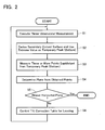
- the computer 200 runs a certain aspherical workpiece leveling program to execute the process as shown in Fig. 2.
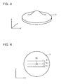
- the aspherical workpiece to be measured in this embodiment is such the workpiece 2 that has a uniform tilt at positions equidistant from the peak, for example, as shown in Fig. 3.
- the surface of such the aspherical workpiece 2 is scanned along a plurality of scan lines L1, L2, L3 and so on located at a certain distance from each other in the Y-direction as shown in Fig. 4.
- the height of each point in the Z-direction is sampled and acquired as three-dimensionally measured data.
- a secondary curved surface is derived from the acquired three-dimensionally measured data,and an extreme value of this secondary curved surface is obtained as a temporary peak point (or bottom point) P0 as shown in Fig. 4 (S2).
- P0 is a temporary peak value to the last.
- Fig. 5 Fig. 5
- four points P1, P2, P3, P4 are measured. Desirably, the four points are selected as uniform as possible.
- the measured points P1-P4 are measured on a point-by-point basis while moving the stylus 9.
- Such the measurement of the measured points on a point-by-point basis may be replaced as shown in Fig. 6.
- mutually parallel scan lines L4, L5 are set through positions, which sandwich the temporary peak point P0 therebetween and are at a distance, d, from the peak point P0 in the Y-direction, respectively.
- These scan lines L4, L5 and the circle of radius r have cross points P5, P6, P7, P8 therebetween, which may be obtained as the measured points.
- a plane Sa is determined from the obtained three or more measured points (S4).
- the plane Sa can be determined in a single way.
- the plane may be determined as a least- square plane.
- the obtained plane Sa is determined if it can be regarded as an almost horizontal plane in accordance with whether an error between the direction of the normal and the direction of the standard axis (Z-axis) falls within a certain range (for example, ⁇ 1°) (S5). If the obtained plane Sa can be regarded as an almost horizontal plane, the temporary peak value P0 is employed as a true peak value P0' , and the control goes to the curved surface analysis.
- the tilt correction-functioned movable table 5 is subjected to tilt correction to tilt-correct the workpiece 2 such that the plane Sa becomes an almost horizontal plane as shown in Fig. 8 (S6).
- the peak value also transfers from P0 to P0' . So the process is repeated again from the step S1. This process is repeated until the plane can be regarded as an almost horizontal plane in the step S5 to finish the process of leveling the aspherical workpiece 2.
- Fig. 9 is a flowchart showing a process of leveling an aspherical workpiece according to another embodiment of the present invention.
- leveling is performed based on the peak value of the workpiece.
- another extreme value of the workpiece, or a bottom value may be employed for leveling.
Landscapes
- Physics & Mathematics (AREA)
- General Physics & Mathematics (AREA)
- Geometry (AREA)
- Chemical & Material Sciences (AREA)
- Analytical Chemistry (AREA)
- Length Measuring Devices With Unspecified Measuring Means (AREA)
- A Measuring Device Byusing Mechanical Method (AREA)
Abstract
Description
- The present invention relates to an aspherical workpiece leveling method and program applicable to a contour measuring machine including a tilt correction table and the like.
- Generally, surface form measuring machines have been provided for measuring aspherical forms such as aspherical lenses. One of such the surface form measuring machines comprises an optical measuring probe, and a first rotating means and a second rotating means forming a certain angle therebetween. These rotating means are used to rotate the optical measuring probe to match the optical axis of the measuring probe with all directions of the normal to a target surface to be measured. This makes it possible to accurately measure the surface form of even a complicated aspherical form, as known (
JP-A 11-211426 - A surface texture measuring machine may comprise a stylus for scanning a target surface to measure the surface texture of the target surface. This machine comprises a tilt adjuster provided on a measuring table for centering a cylindrical form and a conical form, as known (
JP-A 2000-266534 USP 6,745,616 , Document 2b). - The machine disclosed in the above-described Document 1, however, requires rotations of the measuring probe about two axes having a certain angle, and accordingly causes a problem associated with the large scale of the machine.
Documents 2 failed to disclose an appropriate method of leveling an aspherical workpiece with unknown design values. The machine disclosed inDocuments 2 is capable of measuring the table with the workpiece mounted thereon for leveling while leaving the positional relation between the workpiece and the table unknown. In other words, it can not exclude the influence due to the workpiece attachment error always. - In one aspect the present invention provides an aspherical workpiece leveling method of leveling an aspherical workpiece mounted on a tilt correction table. The method comprises three-dimensionally measuring a surface of the aspherical workpiece containing an extreme value; deriving a secondary curved surface from the obtained three-dimensionally measured values to obtain an extreme value of the secondary curved surface as a temporary extreme value; obtaining three-dimensionally measured values at three or more points from the surround about the obtained temporary extreme value; obtaining a plane defined by the obtained three-dimensionally measured values at three or more points; and adjusting the tilt correction table for leveling the obtained plane.
- In another aspect the present invention provides an aspherical workpiece leveling method of leveling an aspherical workpiece mounted on a tilt correction table. The method comprises three-dimensionally measuring a surface of the aspherical workpiece containing an extreme value; deriving a secondary curved surface from the obtained three-dimensionally measured values to obtain an extreme value of the secondary curved surface as a temporary extreme value; obtaining three-dimensionally measured values at three or more points from the surround about the obtained temporary extreme value; obtaining a plane defined by the obtained three-dimensionally measured values at three or more points; determining whether the obtained plane and the horizontal plane have an error falling within a certain range and terminating the process if the error falls within the certain range; and adjusting the tilt correction table for leveling the obtained plane if the error falls outside the certain range, prior to the return to the step of three-dimensionally measuring the aspherical workpiece, wherein the above steps are repeated until the error falls within the certain range.
- In one aspect the present invention provides a computer-executable aspherical workpiece leveling program for leveling an aspherical workpiece mounted on a tilt correction table. The program comprises three-dimensionally measuring a surface of the aspherical workpiece containing an extreme value; deriving a secondary curved surface from the obtained three-dimensionally measured values to obtain an extreme value of the secondary curved surface as a temporary extreme value; obtaining three-dimensionally measured values at three or more points from the surround about the obtained temporary extreme value; obtaining a plane defined by the obtained three-dimensionally measured values at three or more points; and adjusting the tilt correction table for leveling the obtained plane.
- The present invention will be more fully understood from the following detailed description with reference to the accompanying drawings in which:
- Fig. 1 is an external perspective view showing an arrangement of a contour measuring machine according to an embodiment of this invention;
- Fig. 2 is a flowchart showing a process of leveling an asphericalworkpiece, which is executed in the measuring machine ;
- Fig. 3 is a perspective view showing an aspherical workpiece to be leveled;
- Fig. 4 is a plan view of a workpiece illustrative of the contents of the process of leveling;
- Fig. 5 is a plan view of a workpiece illustrative of the contents of the process of leveling;
- Fig. 6 is a plan view of a workpiece illustrative of the contents of the process of leveling;
- Fig. 7 is a side view of a workpiece illustrative of the contents of the process of leveling;
- Fig. 8 is a side view of a workpiece illustrative of the contents of the process of leveling; and
- Fig. 9 is a flowchart showing a process of leveling an aspherical workpiece according to another embodiment of the present invention.
- Fig. 1 is an external perspective view of a
form measuring machine 100 according to an embodiment of this invention. The form measuring machine is a contour measuring machine in this example. Alternatively, it may be another form measuring machine such as a three-dimensional measuring machine and a non-contact image measuring machine. - The major part of the
machine 100 is mounted on a table 1, on which a workpiece mount table 3 is provided to receive aworkpiece 2 mounted thereon. The workpiece mount table 3 includes abase plate 4, and a movable table 5 that moves in the X-direction (lateral direction) in the figure over thebase plate 4 and shifts theworkpiece 2 in the Y-direction (direction orthogonal to the page) in Fig. 1. The movable table 5 also serves as a tilt adjustment-functioned table capable of adjusting the mounted surface of theworkpiece 2 in any attitude. The table 1 is fixedly provided with acolumn 6 that extends in the vertical direction. Thecolumn 6 is equipped with aslider 7 that is movable in the vertical direction. Theslider 7 is equipped with astylus arm 8. Thestylus arm 8 is driven in the horizontal (X) direction on operation from aconsole 10 to trace a surface of theworkpiece 2 with astylus 9 provided at the tip of the stylus arm. As a result, a height, Z, of the surface at each position in the X-direction can be obtained as measured data. When the movable table 5 moves theworkpiece 2 in the Y-direction , scan lines extending in the X-direction can be switched among them. - The measured data is fed into a
computer 200 and subjected to form analysis. If theworkpiece 2 is an aspherical workpiece, a process of leveling the aspherical workpiece is executed prior to the form analysis. Thecomputer 200 runs a certain aspherical workpiece leveling program to execute the process as shown in Fig. 2. - First, a three-dimensional measurement is executed (S1). The aspherical workpiece to be measured in this embodiment is such the
workpiece 2 that has a uniform tilt at positions equidistant from the peak, for example, as shown in Fig. 3. In the case of the contour measuring machine, the surface of such theaspherical workpiece 2 is scanned along a plurality of scan lines L1, L2, L3 and so on located at a certain distance from each other in the Y-direction as shown in Fig. 4. As a result, the height of each point in the Z-direction is sampled and acquired as three-dimensionally measured data. - Next, a secondary curved surface is derived from the acquired three-dimensionally measured data,and an extreme value of this secondary curved surface is obtained as a temporary peak point (or bottom point) P0 as shown in Fig. 4 (S2). In this stage, as the
workpiece 2 has not yet been leveled, P0 is a temporary peak value to the last. - Subsequently, three or more points are measured on a circumference of radius, r, about the temporary peak point P0 as shown in Fig. 5 (S3) . In this example, four points P1, P2, P3, P4 are measured. Desirably, the four points are selected as uniform as possible. The measured points P1-P4 are measured on a point-by-point basis while moving the
stylus 9. Such the measurement of the measured points on a point-by-point basis may be replaced as shown in Fig. 6. In this case, mutually parallel scan lines L4, L5 are set through positions, which sandwich the temporary peak point P0 therebetween and are at a distance, d, from the peak point P0 in the Y-direction, respectively. These scan lines L4, L5 and the circle of radius r have cross points P5, P6, P7, P8 therebetween, which may be obtained as the measured points. - Next, as shown in Fig. 7, a plane Sa is determined from the obtained three or more measured points (S4). In the case of three measured points, the plane Sa can be determined in a single way. In the case of four or more measured points, however, the plane may be determined as a least- square plane. The obtained plane Sa is determined if it can be regarded as an almost horizontal plane in accordance with whether an error between the direction of the normal and the direction of the standard axis (Z-axis) falls within a certain range (for example, ± 1°) (S5). If the obtained plane Sa can be regarded as an almost horizontal plane, the temporary peak value P0 is employed as a true peak value P0' , and the control goes to the curved surface analysis. To the contrary, if it can not be regarded as an almost horizontal plane, the tilt correction-functioned movable table 5 is subjected to tilt correction to tilt-correct the
workpiece 2 such that the plane Sa becomes an almost horizontal plane as shown in Fig. 8 (S6). As a result, the peak value also transfers from P0 to P0' . So the process is repeated again from the step S1. This process is repeated until the plane can be regarded as an almost horizontal plane in the step S5 to finish the process of leveling theaspherical workpiece 2. - Fig. 9 is a flowchart showing a process of leveling an aspherical workpiece according to another embodiment of the present invention.
- In this embodiment, after the plane is determined in the step S4, an error between the plane and the horizontal plane is obtained (S15). Then, the tilt correction table is controlled by the obtained error for leveling (S16). This makes it possible to level the aspherical workpiece in a shorter period of time than the preceding embodiment.
- In the above examples, leveling is performed based on the peak value of the workpiece. Alternatively, another extreme value of the workpiece, or a bottom value, may be employed for leveling.
Claims (9)
- An aspherical workpiece leveling method of leveling an aspherical workpiece mounted on a tilt correction table, comprising:three-dimensionally measuring a surface of the aspherical workpiece containing an extreme value;deriving a secondary curved surface from the obtained three-dimensionally measured values to obtain an extreme value of the secondary curved surface as a temporary extreme value;obtaining three-dimensionally measured values at three or more points from the surround about the obtained temporary extreme value;obtaining a plane defined by the obtained three-dimensionally measured values at three or more points; andadjusting the tilt correction table for leveling the obtained plane.
- The aspherical workpiece leveling method according to claim 1, wherein the step of obtaining three-dimensionally measured values at three or more points includes obtaining three-dimensionally measured values at points equidistant from the obtained temporary extreme value.
- The aspherical workpiece leveling method according to claim 1, wherein the step of obtaining three-dimensionally measured values at three or more points includes locating the obtained temporary extreme value inward, and obtaining three-dimensionally measured values at points on mutually parallel scan lines equidistant from the temporary extreme value.
- The aspherical workpiece leveling method according to claim 1, wherein the aspherical workpiece has a uniform tilt at positions equidistant from the peak.
- An aspherical workpiece leveling method of leveling an aspherical workpiece mounted on a tilt correction table, comprising:three-dimensionally measuring a surface of the aspherical workpiece containing an extreme value;deriving a secondary curved surface from the obtained three-dimensionally measured values to obtain an extreme value of the secondary curved surface as a temporary extreme value;obtaining three-dimensionally measured values at three or more points from the surround about the obtained temporary extreme value;obtaining a plane defined by the obtained three-dimensionally measured values at three or more points;determining whether the obtained plane and the horizontal plane have an error falling within a certain range and terminating the process if the error falls within the certain range; andadjusting the tilt correction table for leveling the obtained plane if the error falls outside the certain range, prior to the return to the step of three-dimensionally measuring the aspherical workpiece,wherein the above steps are repeated until the error falls within the certain range.
- The aspherical workpiece leveling method according to claim 5, wherein the step of obtaining three-dimensionally measured values at three or more points includes obtaining three-dimensionally measured values at points equidistant from the obtained temporary extreme value.
- The aspherical workpiece leveling method according to claim 5, wherein the step of obtaining three-dimensionally measured values at three or more points includes locating the obtained temporary extreme value inward, and obtaining three-dimensionally measured values at points on mutually parallel scan lines equidistant from the temporary extreme value.
- The aspherical workpiece leveling method according to claim 5, wherein the aspherical workpiece has a uniform tilt at positions equidistant from the peak.
- A computer-executable aspherical workpiece leveling program for leveling an aspherical workpiece mounted on a tilt correction table, comprising:three-dimensionally measuring a surface of the aspherical workpiece containing an extreme value;deriving a secondary curved surface from the obtained three-dimensionally measured values to obtain an extreme value of the secondary curved surface as a temporary extreme value;obtaining three-dimensionally measured values at three or more points from the surround about the obtained temporary extreme value;obtaining a plane defined by the obtained three-dimensionally measured values at three or more points; andadjusting the tilt correction table for leveling the obtained plane.
Applications Claiming Priority (1)
| Application Number | Priority Date | Filing Date | Title |
|---|---|---|---|
| JP2005062700 | 2005-03-07 |
Publications (1)
| Publication Number | Publication Date |
|---|---|
| EP1703252A1 true EP1703252A1 (en) | 2006-09-20 |
Family
ID=36570319
Family Applications (1)
| Application Number | Title | Priority Date | Filing Date |
|---|---|---|---|
| EP06004395A Withdrawn EP1703252A1 (en) | 2005-03-07 | 2006-03-03 | Method and program for leveling aspherical workpieces |
Country Status (3)
| Country | Link |
|---|---|
| US (1) | US7277818B2 (en) |
| EP (1) | EP1703252A1 (en) |
| CN (1) | CN1831472A (en) |
Families Citing this family (4)
| Publication number | Priority date | Publication date | Assignee | Title |
|---|---|---|---|---|
| US7650201B2 (en) * | 2004-09-03 | 2010-01-19 | Nippon Mining & Metals Co., Ltd. | Determination method and processing method of machined surface of plate-like material, and apparatus for use in said methods |
| US7991501B2 (en) * | 2006-03-06 | 2011-08-02 | Jx Nippon Mining & Metals Corporation | Method for determining machining plane of planar material, machining method and device for determining machining plane and flat surface machining device |
| JP5270246B2 (en) * | 2008-07-28 | 2013-08-21 | 株式会社ミツトヨ | Surface texture measuring instrument and measuring method |
| KR101914101B1 (en) | 2011-06-28 | 2018-11-02 | 삼성전자 주식회사 | Apparatus and method of controlling chuck, and exposure apparatus and control method thereof |
Citations (4)
| Publication number | Priority date | Publication date | Assignee | Title |
|---|---|---|---|---|
| DE4207201A1 (en) * | 1991-03-07 | 1992-10-01 | Mitutoyo Corp | LEVELING METHOD AND DEVICE |
| JPH11211426A (en) | 1998-01-29 | 1999-08-06 | Fuji Xerox Co Ltd | Surface form measuring device |
| JP2000266534A (en) | 1999-01-12 | 2000-09-29 | Mitsutoyo Corp | Surface profile measuring apparatus, inclination adjuster therefor and method for adjusting attitude of object |
| DE10052206A1 (en) * | 1999-10-21 | 2001-06-28 | Mitutoyo Corp | Surface characteristics measurement machine for measuring surface of target objects having ridgelines, has swivel adjustment unit which is operated manually to adjust positional target object within XY flat surface |
-
2006
- 2006-03-03 EP EP06004395A patent/EP1703252A1/en not_active Withdrawn
- 2006-03-06 US US11/368,753 patent/US7277818B2/en not_active Expired - Fee Related
- 2006-03-07 CN CNA2006100588979A patent/CN1831472A/en active Pending
Patent Citations (5)
| Publication number | Priority date | Publication date | Assignee | Title |
|---|---|---|---|---|
| DE4207201A1 (en) * | 1991-03-07 | 1992-10-01 | Mitutoyo Corp | LEVELING METHOD AND DEVICE |
| JPH11211426A (en) | 1998-01-29 | 1999-08-06 | Fuji Xerox Co Ltd | Surface form measuring device |
| JP2000266534A (en) | 1999-01-12 | 2000-09-29 | Mitsutoyo Corp | Surface profile measuring apparatus, inclination adjuster therefor and method for adjusting attitude of object |
| DE10052206A1 (en) * | 1999-10-21 | 2001-06-28 | Mitutoyo Corp | Surface characteristics measurement machine for measuring surface of target objects having ridgelines, has swivel adjustment unit which is operated manually to adjust positional target object within XY flat surface |
| US6745616B1 (en) | 1999-10-21 | 2004-06-08 | Mitutoyo Corporation | Surface texture measuring machine, leveling device for surface texture measuring machine and orientation-adjusting method of workpiece of surface texture measuring machine |
Also Published As
| Publication number | Publication date |
|---|---|
| US20060196063A1 (en) | 2006-09-07 |
| US7277818B2 (en) | 2007-10-02 |
| CN1831472A (en) | 2006-09-13 |
Similar Documents
| Publication | Publication Date | Title |
|---|---|---|
| US9383198B2 (en) | Method and device for reducing errors in a turning device during the determination of coordinates of a workpiece or during the machining of a workpiece | |
| US11499817B2 (en) | Coordinate measuring machine with vision probe for performing points-from-focus type measurement operations | |
| US20150052768A1 (en) | Method for determining the axis of the rotary table in a coordinate measuring machine | |
| KR101629545B1 (en) | Shape measuring device, shape measuring method, structure manufacturing method, and program | |
| CN110030962B (en) | Lens measuring device and lens measuring method | |
| JP6316858B2 (en) | Automatic measuring device for motor shaft accuracy | |
| JP3678915B2 (en) | Non-contact 3D measuring device | |
| CN102042813A (en) | Surface texture measuring machine and a surface texture measuring method | |
| KR20060113967A (en) | Geometric adjustment method of multi-axis metrology system | |
| GB2378254A (en) | Profilometer and method for measuring surface profile and calibration method | |
| CN113465513B (en) | Laser sensor inclination angle error measurement compensation method and system based on cylindrical angle square | |
| US20110275280A1 (en) | Method of auto scanning and scraping a work piece for a hard rail | |
| JP2002257535A (en) | Position measuring device | |
| US20030069708A1 (en) | Method for calibrating probe and computer-readable medium | |
| US20230152772A1 (en) | Positional relationship measurement method and machining apparatus | |
| EP2068113A1 (en) | Calibrating method of image measuring instrument | |
| JP2001157951A (en) | Shape accuracy measuring device by sequential two-point method and laser displacement meter interval measuring method for shape accuracy measurement by sequential two-point method | |
| CN109387172A (en) | Thread spindle measuring device, thread spindle measurement method and adjustment fixture | |
| JP5693662B2 (en) | Automatic centering method of displacement measuring instrument and machine tool having displacement measuring function | |
| JP2021156714A (en) | Straightness measuring system, displacement sensor calibration method and straightness measuring method | |
| JPH11351841A (en) | Noncontact type three-dimensional measuring method | |
| US7277818B2 (en) | Method and program for leveling aspherical workpieces | |
| US5107132A (en) | Apparatus for the verification of corrected surfaces or in the process of correction | |
| JPH11351840A (en) | Noncontact type three-dimensional measuring method | |
| CN216846033U (en) | Inner wall measuring system based on deep rise workpiece |
Legal Events
| Date | Code | Title | Description |
|---|---|---|---|
| PUAI | Public reference made under article 153(3) epc to a published international application that has entered the european phase |
Free format text: ORIGINAL CODE: 0009012 |
|
| AK | Designated contracting states |
Kind code of ref document: A1 Designated state(s): AT BE BG CH CY CZ DE DK EE ES FI FR GB GR HU IE IS IT LI LT LU LV MC NL PL PT RO SE SI SK TR |
|
| AX | Request for extension of the european patent |
Extension state: AL BA HR MK YU |
|
| 17P | Request for examination filed |
Effective date: 20061220 |
|
| 17Q | First examination report despatched |
Effective date: 20070129 |
|
| AKX | Designation fees paid |
Designated state(s): DE FR GB |
|
| STAA | Information on the status of an ep patent application or granted ep patent |
Free format text: STATUS: THE APPLICATION IS DEEMED TO BE WITHDRAWN |
|
| 18D | Application deemed to be withdrawn |
Effective date: 20070809 |