EP1703192A1 - Bayonet coupling - Google Patents
Bayonet coupling Download PDFInfo
- Publication number
- EP1703192A1 EP1703192A1 EP05005539A EP05005539A EP1703192A1 EP 1703192 A1 EP1703192 A1 EP 1703192A1 EP 05005539 A EP05005539 A EP 05005539A EP 05005539 A EP05005539 A EP 05005539A EP 1703192 A1 EP1703192 A1 EP 1703192A1
- Authority
- EP
- European Patent Office
- Prior art keywords
- bayonet connection
- connection
- connection according
- connecting piece
- annular bead
- Prior art date
- Legal status (The legal status is an assumption and is not a legal conclusion. Google has not performed a legal analysis and makes no representation as to the accuracy of the status listed.)
- Granted
Links
- 230000008878 coupling Effects 0.000 title 1
- 238000010168 coupling process Methods 0.000 title 1
- 238000005859 coupling reaction Methods 0.000 title 1
- 239000011324 bead Substances 0.000 claims description 39
- 238000010438 heat treatment Methods 0.000 claims description 15
- 238000003780 insertion Methods 0.000 claims description 15
- 230000037431 insertion Effects 0.000 claims description 15
- 238000007789 sealing Methods 0.000 claims description 13
- 238000002347 injection Methods 0.000 claims description 8
- 239000007924 injection Substances 0.000 claims description 8
- 239000004033 plastic Substances 0.000 claims description 6
- 239000002184 metal Substances 0.000 description 4
- 238000005304 joining Methods 0.000 description 3
- 150000001875 compounds Chemical class 0.000 description 2
- 230000002349 favourable effect Effects 0.000 description 2
- 238000004519 manufacturing process Methods 0.000 description 2
- 238000000034 method Methods 0.000 description 2
- XLYOFNOQVPJJNP-UHFFFAOYSA-N water Substances O XLYOFNOQVPJJNP-UHFFFAOYSA-N 0.000 description 2
- 230000000712 assembly Effects 0.000 description 1
- 238000000429 assembly Methods 0.000 description 1
- 230000005540 biological transmission Effects 0.000 description 1
- 230000001419 dependent effect Effects 0.000 description 1
- 238000007373 indentation Methods 0.000 description 1
- 238000001746 injection moulding Methods 0.000 description 1
- 239000002991 molded plastic Substances 0.000 description 1
- 238000007493 shaping process Methods 0.000 description 1
- 238000004513 sizing Methods 0.000 description 1
- 238000003860 storage Methods 0.000 description 1
Images


Classifications
-
- F—MECHANICAL ENGINEERING; LIGHTING; HEATING; WEAPONS; BLASTING
- F16—ENGINEERING ELEMENTS AND UNITS; GENERAL MEASURES FOR PRODUCING AND MAINTAINING EFFECTIVE FUNCTIONING OF MACHINES OR INSTALLATIONS; THERMAL INSULATION IN GENERAL
- F16L—PIPES; JOINTS OR FITTINGS FOR PIPES; SUPPORTS FOR PIPES, CABLES OR PROTECTIVE TUBING; MEANS FOR THERMAL INSULATION IN GENERAL
- F16L37/00—Couplings of the quick-acting type
- F16L37/08—Couplings of the quick-acting type in which the connection between abutting or axially overlapping ends is maintained by locking members
- F16L37/10—Couplings of the quick-acting type in which the connection between abutting or axially overlapping ends is maintained by locking members using a rotary external sleeve or ring on one part
- F16L37/113—Couplings of the quick-acting type in which the connection between abutting or axially overlapping ends is maintained by locking members using a rotary external sleeve or ring on one part the male part having lugs on its periphery penetrating into the corresponding slots provided in the female part
-
- F—MECHANICAL ENGINEERING; LIGHTING; HEATING; WEAPONS; BLASTING
- F24—HEATING; RANGES; VENTILATING
- F24H—FLUID HEATERS, e.g. WATER OR AIR HEATERS, HAVING HEAT-GENERATING MEANS, e.g. HEAT PUMPS, IN GENERAL
- F24H9/00—Details
- F24H9/12—Arrangements for connecting heaters to circulation pipes
- F24H9/13—Arrangements for connecting heaters to circulation pipes for water heaters
-
- F—MECHANICAL ENGINEERING; LIGHTING; HEATING; WEAPONS; BLASTING
- F24—HEATING; RANGES; VENTILATING
- F24H—FLUID HEATERS, e.g. WATER OR AIR HEATERS, HAVING HEAT-GENERATING MEANS, e.g. HEAT PUMPS, IN GENERAL
- F24H9/00—Details
- F24H9/14—Arrangements for connecting different sections, e.g. in water heaters
- F24H9/142—Connecting hydraulic components
Abstract
Description
Die Erfindung betrifft eine Bajonettverbindung mit den im Oberbegriff des Anspruch 1 angegebenen Merkmalen.The invention relates to a bayonet connection with the features specified in the preamble of claim 1.
Bajonettverbindungen der eingangs genannten Art dienen typischerweise zum Herstellen von fluidleitenden Verbindungen, beispielsweise von Rohrleitungen untereinander, von Rohrleitungen mit Vorrichtungen wie beispielsweise Baueinheiten von Kompaktheizungsanlagen (Heizthermen) oder auch zum Einsatz einer Baugruppe in eine Vorrichtung wie beispielsweise eines Differenzdruckaufnehmers in einer Baueinheit für eine Kompaktheizungsanlage.Bayonet connections of the type initially mentioned are typically used for the production of fluid-conducting connections, for example of pipelines with one another, of pipelines with devices such as assemblies of compact heating systems (heating baths) or also for use of an assembly in a device such as a differential pressure transducer in a unit for a compact heating system.
Bei derartigen fluidführenden Bajonettverbindungen zählt es insbesondere im Zusammenhang mit Kompaktheizungsanlagen zum Stand der Technik, Anschlussstutzen und Anschlusskörper so auszubilden, dass sie ineinander einsteckbar und dann durch Drehen um deren Einsteckachse zueinander in Ensteckrichtung verriegelbar sind. Eine solche Bajonettverbindung setzt jedoch stets die freie Drehbarkeit eines der beiden Bauteile voraus, was häufig nicht gegeben ist.In such fluid-conducting bayonet joints, it is particularly in connection with compact heating systems of the prior art, connecting stub and connecting body in such a way that they are plugged into each other and then locked by turning about their Einsteckachse each other in Ensteckrichtung. However, such a bayonet connection always requires the free rotation of one of the two components, which is often not the case.
Für letzteren Anwendungsfall ist es bekannt, statt einer Bajonettverbindung eine alternative Formschlussverbindung zu wählen, bei der seitlich über Ausnehmungen im Anschlussstutzen ein Metallbügel eingefügt wird, welcher den im Anschlussstutzen steckenden Anschlusskörper formschlüssig in Einsteckrichtung verriegelt. Nachteilig bei diesen Formschlussverbindungen mittels Bügel ist allerdings, dass im Anschlussstutzen Ausnehmungen für den quer zur Einsteckrichtung einfügbaren Bügel vorgesehen sein müssen. Wenn solch ein Anschlussstutzen an einer Baueinheit für eine Kompaktheizungsanlage vorgesehen sein soll, die regelmäßig als Kunststoffspritzgussteil ausgebildet ist, dann bedingt dies, dass für die Herstellung ein Werkzeug erforderlich ist, welches zumindest in Teilen quer zur Stutzenlängsachse verfahrbar ist. Aufgrund der immer kompakteren Bauweise und Komplexität dieser Bauteile ist dies häufig jedoch nicht oder nur mit vergleichsweise hohem Aufwand möglich.For the latter application, it is known, instead of a bayonet connection to choose an alternative form-fitting connection, in which laterally via recesses in the connecting piece a metal bracket is inserted, which locks the connecting piece in the connector body in a form-fitting manner in the insertion direction. A disadvantage of these form-fitting connections by means of brackets, however, is that in the connection piece Recesses must be provided for the insertable transversely to the insertion strap. If such a connection piece to be provided on a unit for a compact heating system, which is regularly designed as a plastic injection molded part, then this means that for the production of a tool is required, which is at least in parts transversely to the nozzle longitudinal axis movable. Due to the increasingly compact design and complexity of these components, however, this is often not possible or only with relatively high effort.
Vor diesem Hintergrund liegt der vorliegenden Erfindung die Aufgabe zugrunde, eine Bajonettverbindung zu schaffen, bei welcher der Anschlussstutzen an seiner Außenseiten ohne jegliche Hinterschneidung oder Einformung ausgebildet sein kann. Darüber hinaus soll die Bajonettverbindung so ausgebildet sein, dass Anschlussstutzen und Anschlusskörper lediglich in einer, nämlich in Einsteckrichtung zueinander bewegbar sein müssen.Against this background, the present invention seeks to provide a bayonet connection, in which the connection piece can be formed on its outer sides without any undercut or indentation. In addition, the bayonet connection should be designed so that connection piece and connection body only in one, namely in the insertion direction to each other must be movable.
Diese Aufgabe wird gemäß der Erfindung durch die in Anspruch 1 angegebenen Merkmale gelöst. Vorteilhafte Ausgestaltungen der Erfindung ergeben sich aus den Unteransprüchen, der nachfolgenden Beschreibung und der Zeichnung.This object is achieved according to the invention by the features specified in claim 1. Advantageous embodiments of the invention will become apparent from the dependent claims, the following description and the drawings.
Grundgedanke der vorliegenden Erfindung ist es, die Bajonettverbindung so auszubilden, dass ein gesonderter zwischen Anschlusskörper und Anschlussstutzen eingliederbarer Riegelkörper vorgesehen ist, der durch einfaches Drehen um die Einsteckachse ver- bzw. entriegelbar ist. Der Vorteil der erfindungsgemäßen Bajonettverbindung liegt also darin, dass die zu verbindenden Teile, nämlich der Anschlussstutzen und der Anschlusskörper - dieser kann natürlich auch ein stutzenähnliches Gebilde sein - nur in Richtung ihrer Längsachse zueinander bewegbar sein müssen und die Verriegelung durch den beispielsweise bügelförmig ausgebildeten Riegelkörper erfolgt, welcher zwischen Anschlussstutzen und Anschlusskörper eingegliedert ist und der durch Drehen um die Einsteckachse die Bauteile zueinander verriegelt bzw. entriegelt. Dadurch, dass der Riegelkörper zwischen Anschlusskörper und Anschlussstutzen eingegliedert ist, also Riegelkörper und Anschlusskörper in den Anschlussstutzen eingreifen, kann der Anschlussstutzen an seiner Außenseite völlig glattwandig und ohne Hinterschneidung ausgebildet sein, was insbesondere bei dem eingangs genannten Anwendungsbereich, (Baueinheit für eine Kompaktheizungsanlage) oder anderen komplexen Spritzgussbauteilen von besonderem Vorteil ist, da der Werkzeugaufbau wesentlich vereinfacht wird. Der beim Spritzengießen im Anschlussstutzen befindliche Kem muss ohnehin vorgesehen sein und vor dem Entformen gezogen werden. Bei geeigneter Formgebung kann dies in einfacher Weise gegebenenfalls nach Drehen des Kerns um seine Ziehachse erfolgen.The basic idea of the present invention is to design the bayonet connection in such a way that a separate locking body, which can be inserted between connection body and connecting piece, is provided which can be locked or unlocked by simply rotating about the insertion axis. The advantage of the bayonet connection according to the invention is therefore that the parts to be joined, namely the connecting piece and the connection body - this may of course be a clip-like structure - only in the direction of their longitudinal axis to each other must be movable and the locking is done by the example bow-shaped locking body , which between connecting pieces and connection body is incorporated and locked by unlocking the components to each other by rotating around the insertion axis. Due to the fact that the locking body is integrated between connecting body and connecting piece, ie locking body and connecting body engage in the connecting piece, the connecting piece can be formed on its outside completely smooth-walled and without undercut, which in particular in the application area mentioned above, (unit for a compact heating system) or other complex injection molded components is particularly advantageous, since the tool design is greatly simplified. The core located in the connecting piece during injection molding must be provided anyway and pulled out before removal from the mold. With suitable shaping, this can be done in a simple manner, optionally after turning the core about its draw axis.
Unter Bajonettverbindungen im Sinne der vorliegenden Erfindung wird eine Verbindung verstanden, bei der eine formschlüssige Verbindung durch eine translatorische Bewegung einerseits und eine rotatorische Bewegung andererseits erreicht wird, typischerweise wird zum Verbinden zunächst die translatorische hier Einsteckbewegung vom Anschlusskörper in den Anschlussstutzen erfolgen, wonach zum Verriegeln die rotatorische Bewegung, nämlich das Drehen des Verriegelungskörpers erfolgt. Das Lösen der Verbindung erfolgt in umgekehrter Reihenfolge.In the context of the present invention, bayonet connections are understood as meaning a connection in which a positive connection is achieved by a translational movement on the one hand and a rotational movement on the other hand. Typically, the translational insertion movement from the connection body into the connecting piece will initially take place for connection, after which the locking mechanism will be used rotational movement, namely the rotation of the locking body takes place. The connection is released in reverse order.
Vorteilhaft weist der Anschlussstutzen mindestens einen nach innen ragenden Vorsprung und der Anschlusskörper mindestens einen am Außenumfang angeordneten und nach außen ragenden Vorsprung auf, die so zueinander angeordnet sind, dass der Anschlusskörper in den Anschlussstutzen einsteckbar ist, ohne dass die gegenseitigen Vorsprünge kollidieren. Die Vorsprünge dienen erst in Verbindung mit dem Riegelkörper zur formschlüssigen Festlegung vom Anschlusskörper im Anschlussstutzen.Advantageously, the connecting piece has at least one inwardly projecting projection and the connecting body at least one arranged on the outer circumference and outwardly projecting projection, which are arranged to each other, that the connecting body can be inserted into the connecting piece without the mutual projections collide. The projections are used only in conjunction with the Bar body for positive fixing of the connection body in the connection piece.
Vorteilhaft ist es, wenn der nach außen ragende Vorsprung des Anschlusskörpers durch einen umlaufenden Ringwulst gebildet ist. Solche Ringwülste können auf einfache Weise gegebenenfalls sogar Vorort an vorhandenen Metallrohren durch Stauchen oder andere geeignete Kaltverformungen gebildet werden, so dass die erfindungsgemäße Bajonettverbindung auch mit Anschlusskörpem in Form von Rohrenden möglich ist, die Vorort vorhanden sind und lediglich mit einem geeigneten Werkzeug angepasst werden müssen. Der umlaufende Wulst erlaubt zu dem eine sichere Übertragung von Axialkräften und erleichtert den axialen Fügevorgang da keine Ecken und Kanten gebildet sind, die miteinander verhaken könnten.It is advantageous if the outwardly projecting projection of the connection body is formed by a circumferential annular bead. Such annular beads can be formed in a simple manner, possibly even suburb of existing metal pipes by upsetting or other suitable cold deformations, so that the bayonet joint according to the invention is also possible with Anschlußkörpem in the form of pipe ends that are present on site and need to be adapted only with a suitable tool. The circumferential bead allows for the safe transmission of axial forces and facilitates the axial joining process because no corners and edges are formed, which could hook together.
In analoger Weise ist es besonders vorteilhaft, auch den nach innen ragenden Vorsprung durch einen entsprechenden Ringwulst zu bilden. Hierbei sind jedoch abschnittsweise Unterbrechungen erforderlich, um den Riegelkörper zusammen mit dem Anschlusskörper soweit in den Anschlussstutzen einstecken zu können, bis der Ringwulst des Anschlusskörpers in Einsteckrichtung hinter dem Vorsprung bzw. dem durchbrochenen Ringwulst des Anschlussstutzens angeordnet ist, ohne dass dieser an dem nach innen ragenden Vorsprung hängen bleibt.In an analogous manner, it is particularly advantageous to also form the inwardly projecting projection by a corresponding annular bead. However, in some cases interruptions are required in order to be able to insert the locking body together with the connecting body into the connecting piece until the annular bead of the connecting body is arranged in the insertion direction behind the projection or the perforated annular bead of the connection piece, without this protruding on the inwardly projecting Projection sticks.
Um ein Fügen von Anschlusskörper und Anschlussstutzen durch einfaches Ineinanderstecken zu ermöglichen, ist es zweckmäßig, den Innendurchmesser des nach innen ragenden Ringwulstes so zu dimensionieren, dass dieser größer ist als der Außendurchmesser des nach außen ragenden Ringwulstes am Anschlusskörper. Dann nämlich kann der Anschlusskörper in den Anschlussstutzen eingesteckt werden, und zwar so weit bis sein Ringwulst in Einsteckrichtung gesehen hinter dem Ringwulst des Anschlussstutzens liegt. ,In order to enable a joining of connection body and connecting piece by simply nesting, it is expedient to dimension the inner diameter of the inwardly projecting annular bead so that it is greater than the outer diameter of the outwardly projecting annular bead on the connector body. Then that is, the connection body can be inserted into the connecting piece, and indeed until its annular bead seen in the insertion behind the annular bead of the connecting piece. .
Gemäß einer vorteilhaften Weiterbildung der Erfindung ist der Riegelkörper so ausgebildet, dass er den Anschlusskörper seitlich vorzugsweise um etwa 180 ° mit geringem Spiel umgreift und zu einer Seite an dem nach außen ragenden Vorsprung des Anschlusskörpers, vorzugsweise des Ringwulstes anliegt. Dabei ist am Riegelkörper mindestens ein radial nach außen ragender Vorsprung vorgesehen, der durch Drehen des Riegels um die gemeinsame Achse von Anschlusskörper und Anschlussstutzen in eine den Vorsprung des Anschlussstutzens hintergreifende Stellung bewegt. Dabei umgreift der Riegelkörper den Anschlussköper vorzugsweise um etwas mehr als 180 °, dann nämlich kann dieser bügelförmig ausgebildete Riegelkörper durch elastische Aufweitung des Bügels von der Seite auf den Anschlusskörper derart aufgeschoben werden, dass der Bügel durch elastisches Enfedern relativ fest auf dem Anschlusskörper sitzt, so dass er beim Einstecken des Anschlusskörpers in den Anschlussstutzen nicht gesondert gehalten werden muss. Die Dimensionierung erfolgt zweckmäßigerweise so, dass einerseits der Riegelkörper nach seitlichem Aufstecken fest auf dem Anschlusskörper sitzt, andererseits jedoch nach Einstecken der Bauteile in den Anschlussstutzen mit vergleichsweise geringem Kraftaufwand in die verriegelnde Stellung gedreht werden kann.According to an advantageous embodiment of the invention, the locking body is formed so that it laterally surrounds the connecting body preferably by about 180 ° with little play and rests on one side on the outwardly projecting projection of the connecting body, preferably the annular bead. In this case, at least one radially outwardly protruding projection is provided on the latch body, which moves by turning the bolt about the common axis of connection body and connecting piece in a projection of the connecting piece behind engaging position. In this case, the locking body preferably surrounds the connecting body by a little more than 180 °, then namely this bow-shaped locking body can be pushed by elastic expansion of the bracket from the side of the connector body such that the bracket sits by elastic springs relatively firmly on the connector body, so that he does not have to be kept separate when inserting the connector body in the connecting piece. The sizing is expediently such that on the one hand the locking body is firmly seated on the connection body after being pushed on laterally, but on the other hand can be turned into the locking position with comparatively little effort after the components have been inserted into the connecting piece.
Vorzugsweise weist der den Riegelkörper bildende Bügel zwei etwa diametral gegenüber angeordnete radial gerichtete Vorsprünge auf, die so angeordnet sind, dass sie beim Einstecken in den Anschlussstutzen durch die anschlussstutzenseitig entsprechend vorgesehenen Unterbrechung im Ringwulst durchsteckbar sind und beim nachfolgenden Drehen des Riegelkörpers um die Einsteckachse den Anschlusskörper gegenüber dem Anschlussstutzen formschlüssig verriegeln.Preferably, the bracket forming the bar body has two diametrically opposed radially directed projections, which are arranged so that they are plugged through the connection piece side correspondingly provided interruption in the annular bead when plugging into the connecting piece and the connecting body during subsequent rotation of the locking body about the insertion axis lock positively against the connection piece.
Insbesondere wenn mit der erfindungsgemäßen Bajonettverbindung eine fluidführende Leitungsverbindung hergestellt werden soll, ist es zweckmäßig, nicht nur für den mechanischen Verbund, sondern auch für die Dichtheit Sorge zu tragen. Hierzu sind in Weiterbildung der Erfindung Dichtmittel zwischen Anschlusskörper und Anschlussstutzen vorgesehen. Diese können am einfachsten durch einen nahe dem freien Ende des Anschlusskörpers angeordneten umlaufenden Dichtring gebildet sein. Dabei kann entweder in einer Nut des Anschlusskörpers ein O-Ring vorgesehen sein oder aber ein einfacher Dichtring an dem umlaufenden Wulst abgestützt sein, der gegenüber einer entsprechenden Stirnfläche im Anschlussstutzen abdichtet. Bei einer solchen Anordnung ist es zweckmäßig, den nach außen ragenden umlaufenden Wulst des Anschlusskörpers nicht am freien Ende der Rohrleitung vorzusehen, sondem mit geringem Abstand hierzu, um in diesem Bereich die Dichtung eingliedern zu können.In particular, when a fluid-carrying line connection is to be produced with the bayonet connection according to the invention, it is appropriate, not only for the mechanical bond, but also to ensure the tightness. For this purpose, sealing means between connection body and connecting piece are provided in a further development of the invention. These can most easily be formed by a circumferential sealing ring arranged near the free end of the connecting body. In this case, either in a groove of the connecting body, an O-ring may be provided or a simple sealing ring may be supported on the circumferential bead, which seals against a corresponding end face in the connecting piece. In such an arrangement, it is expedient not to provide the outwardly projecting circumferential bead of the connection body at the free end of the pipeline, but at a small distance thereto, to be able to incorporate the seal in this area.
Die erfindungsgemäße Bajonettverbindung kann vorteilhaft für fluidleitende Rohrverbindungen eingesetzt werden, besonders günstig bildet sie Teil einer aus Kunststoffspritzgussteilen aufgebauten Baueinheit für ein Kompaktheizungsaggregat. Dann wird der Anschlussstutzen vorteilhaft als Spritzgussteil einstückig mit der entsprechenden Baueinheit bzw. wenn die Baueinheit mehrteilig aufgebaut ist, mit dem entsprechenden Bauteil ausgebildet werden, was den eingangs dargelegten vereinfachten Werkzeugaufbau mit sich bringt.The bayonet connection according to the invention can be advantageously used for fluid-conducting pipe connections, particularly favorable forms part of a built-up of plastic injection molded structural unit for a compact heating unit. Then the connecting piece is advantageous as an injection molded part in one piece with the corresponding unit or when the unit is constructed in several parts, are formed with the corresponding component, which brings the above-mentioned simplified tool design with it.
So kann es besonders vorteilhaft sein, die zu einer Seite gerichteten Anschlussstutzen der Baueinheit oder eines Teils der Baueinheit so auszubilden, dass sie jeweils Teil einer erfindungsgemäßen Bajonettverbindung bilden.Thus, it can be particularly advantageous to design the connecting pieces of the structural unit or of a part of the structural unit directed to one side such that they each form part of a bayonet connection according to the invention.
Vorteilhaft wird auch der Riegelkörper beispielsweise in Form eines bügelartigen Gebildes als Kunststoffspritzgussteil ausgebildet, und zwar zweckmäßigerweise so, dass er zumindest in der verriegelnden Endstellung vorzugsweise hörbar und fühlbar rastet. Die erfindungsgemäße Bajonettverbindung wird dabei vorteilhaft für Verbindungen innerhalb der Kompaktheizungsanlage eingesetzt, also bei Verbindungen, bei denen typischerweise sowohl Anschlusskörper als auch Anschlussstutzen jeweils Teil eines komplexen Spritzgussbauteils bilden.Advantageously, the bolt body is formed, for example in the form of a bow-shaped structure as a plastic injection molded part, and suitably so that it preferably audibly and tangibly engages at least in the locking end position. The inventive Bayonet connection is advantageously used for connections within the compact heating system, ie in compounds in which typically both connection body and connecting pieces each form part of a complex injection-molded component.
Die erfindungsgemäße Bajonettverbindung kann jedoch auch im Zusammenhang mit vorhandenen Metallrohren angewendet werden, wenn diese zur Bildung des Wulstes entsprechend umgeformt werden, was mit Hilfe eines geeigneten Werkzeugs Vorort gegebenenfalls von Hand erfolgen kann.However, the bayonet joint according to the invention can also be used in conjunction with existing metal pipes, if they are converted accordingly to form the bead, which can be done by hand with the aid of a suitable tool suburb, if necessary.
Die Erfindung ist nachfolgend anhand von in der Zeichnung dargestellten Ausführungsbeispielen näher erläutert. Es zeigen
- Fig. 1
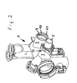
- in vereinfachter perspektivischer Darstellung ein Bauteil einer Baueinheit einer Kompaktheizungsanlage mit einem Anschlussstutzen, ein dazu in Einsteckrichtung mit Abstand angeordnetes Rohrende als Anschlusskörper und einen Riegelkörper,
- Fig. 2
- die Bauteile gemäß Fig. 1 nach Fügen und vor dem Verriegeln der Bajonettverbindung in Darstellung nach Fig. 1,
- Fig. 3
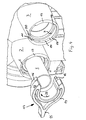
- in vergrößerter Darstellung eine perspektivische Ansicht auf das freie Ende des Anschlusskörpers mit darauf sitzenden Riegelkörper,
- Fig. 4
- in stark vergrößerter Darstellung einen Anschlussstutzen mit eingesteckten Anschlusskörper und noch nicht eingefügten Riegelkörper,
- Fig. 5
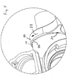
- eine Einzelheit betreffend die Verrastung zwischen Riegelkörper und Anschlussstutzen am Ende des Verriegelvor gangs,
- Fig. 6
- den Riegelkörper in anderer Darstellung zur Veranschaulichung der Rastfunktion und
- Fig. 7
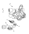
- in perspektivischer Darstellung zwei Bauteile einer anderen Baueinheit einer Kompaktheizungsanlage und deren Verbindung durch das erfindungsgemäße Bajonett.
- Fig. 1
- in a simplified perspective view of a component of a structural unit of a compact heating system with a connection piece, one in the insertion direction at a distance arranged pipe end as a connection body and a bolt body,
- Fig. 2
- 1 after joining and before locking the bayonet connection in the representation of FIG. 1,
- Fig. 3
- in an enlarged view of a perspective view of the free end of the connector body with it sitting bolt body,
- Fig. 4
- in a greatly enlarged representation of a connecting piece with inserted connector body and not yet inserted locking body,
- Fig. 5
- a detail concerning the locking between the locking body and the connecting piece at the end of the locking procedure,
- Fig. 6
- the locking body in another representation to illustrate the locking function and
- Fig. 7
- in perspective view two components of another unit of a compact heating system and their connection through the bayonet according to the invention.
Die anhand der Figuren 1 bis 6 dargestellte Bajonettverbindung ist anhand eines Bauteils 1 in Form eines Spritzgusskunststoffbauteils 1 dargestellt und erläutert, welches Teil einer Baueinheit einer Kompaktheizungsanlage bildet, wie sie beispielsweise in der
Das Bauteil 1 weist zwei nebeneinander angeordnete Anschlussstutzen 2 und 3 auf, die identisch ausgebildet und zur Aufnahme eines hier nur beispielhaft dargestellten Anschusskörpers 4 vorgesehen sind. Der Anschlusskörper 4 ist hier nur beispielhaft dargestellt für ein beliebiges Rohrende oder einen in einen Anschlussstutzen 2 einzubajonetttierenden Körper. Bezogen auf das Bauteil 1 stellt der Anschlusskörper 4 das freie Ende einer zum Wasserspeicher innerhalb der Kompaktheizungsanlage führenden Leitung dar.The component 1 has two adjoining connecting
Der Anschlusskörper 4 besteht aus einem rohrförmigen Teil 5, der mit geringem Abstand vor seinem freien Ende mit einem umlaufenden ringförmigen Wulst 6 versehen ist, welcher sich vom Umfang des rohrförmigen Teils 5 radial nach außen erhebt, so wie dies anhand der Figuren 1 und 3 entnehmbar ist. Der rohrförmige Teil 5 erstreckt sich über den ringförmigen Wulst 6 bis zum freien Ende ein kleines Stück hinaus (siehe Fig. 3) und bildet dort eine radiale Haltefläche für einen Dichtring 7, dessen axiale Anlagefläche durch die zum Rohrende weisende Seite 8 des ringförmigen Wulstes 6 gebildet ist. Bei dem anhand der Figuren 1 bis 6 dargestellten Anschlusskörper 4 ist dieser als Kunststoffspritzgussteil ausgebildet. Ein solcher Anschlusskörper 4 kann jedoch ohne weiteres auch aus einem ortsfesten vorhandenen Metallrohr gebildet werden, in dem der ringförmige Wulst 6 durch Stauchen nahe dem freien Rohrende herausgebildet wird. Dies kann mit einer entsprechenden Vorrichtung erfolgen, solche Umformwerkzeuge zählen insbesondere auch zum Verbinden von Rohrleitungen zum Stand der Technik.The connecting
Die Anschlussstutzen 2, 3 sind, wie insbesondere Fig. 1verdeutlicht, außen völlig glattwandig und ohne Hinterschneidung ausgebildet. Innen sind sie abgestuft ausgebildet, so dass sich eine umlaufende innere Stirnfläche 9 ergibt, welche zur Anlage es Dichtrings 7 dient. Mit Abstand zu dieser Stimfläche 9 weisen die Anschlussstutzen 2 nahe ihrem äußeren (eingangsseitigen) Ende einen nach innen weisenden Vorsprung 10 in Form eines ebenfalls umlaufenden ringförmigen Wulstes auf, der jedoch im Unterschied zu dem ringförmigen Wulst 6 nicht durchgehend sondern zwei sich über ca. 40 ° erstreckende und diametral gegenüber angeordnete Unterbrechungen 11 aufweist.The connecting
Die Dimensionierung von Anschlussstutzen 2, 3 und Anschlusskörper 4 ist so, dass der Anschlusskörper 4, so wie er anhand von Fig. 1 vor dem Anschlussstutzen 2 dargestellt ist, in diesen einschiebbar bzw. einsteckbar ist. Die Einsteckrichtung ist mit 12 gekennzeichnet und liegt auf der übereinstimmenden Längsachse von Anschlussstutzen 2 und Anschlusskörper 4. Der rohrförmige Teil 5 ist insbesondere in seinem über den ringförmigen Wulst 6 hinausragenden Bereich so dimensioniert, dass er bis in den durch die Stirnfläche 9 begrenzten Teil des Anschlussstutzens 2 einschiebbar ist, bis der Dichtring 7 zwischen der Stirnfläche 9 und der Seite 8 des ringförmigen Wulstes 6 anliegt. Weiterhin ist der ringförmige Wulst 6 von seinem Außendurchmesser so dimensioniert, dass er kleiner als der Innendurchmesser des ringförmigen Wulstes 10 ist, so dass dieser mit Spiel durch den durch den ringförmigen Wulst 10 begrenzten Freiraum hindruchführbar ist.The dimensioning of connecting
Um den Anschlusskörper 4 innerhalb eines Anschlussstutzen 2 oder 3 formschlüssig in Richtung 12 oder Gegenrichtung festlegen zu können, ist ein Verriegelungskörper 13 vorgesehen, der einem Bügel 14 mit einem Griffteil 15 aufweist. Der Verriegelungskörper 13 ist einstückig als Kunststoffspritzgussteil ausgebildet und weist zwei seitlich am Bügel 14 diametral angeordnete Vorsprünge 16 auf, die sich wulstförmig auf der Außenseite des Bügels 14 versetzt neben dem Griff 15 erstrecken, und zwar jeweils über einen Winkel der kleiner ist als der über den sich die Unterbrechungen 11 in den Anschlussstutzen erstrecken. Der Bügel 14 ist so dimensioniert, dass er mit seiner Innenkontur zu den Außenabmessungen des rohrförmigen Teils 5 korrespondiert. Er erstreckt sich über einen Winkel von etwas mehr als 180°, so dass beim Aufsetzen des Bügels 14 auf den rohrförmigen Teil 5 des Anschlusskörpers 4, was aus einer Richtung quer zur Richtung 12 erfolgt, sich die Schenkel federnd aufweiten um dann leicht vorgespannt auf dem rohrförmigen Teil 5 so zur Anlage zu kommen, dass der Verriegelungskörper 13 dort fixiert, aber doch bewegbar ist. Der Bügel 14 wird dabei so auf den Anschlussköper 4 aufgeschoben, dass die Vorsprünge 16 mit ihrer einen Seite an der vom Dichtring 7 abgewandten Seite des ringförmigen Wulstes 6 zur Anlage kommen. Es ist darauf zu achten, dass die Vorsprünge 16 so angeordnet sind, dass sie beim Einstecken mit den Unterbrechungen 11 fluchten.In order to be able to fix the
Es wird dann der Anschlusskörper 4 mit dem darauf sitzenden Verriegelungskörper 13 in Richtung 12 in den Anschussstutzen 2 eingesteckt. Dabei wird sowohl der Anschlusskörper 4 in Richtung 12 als auch nachfolgend der Vemegelungskörper 13 in Richtung 12 gedrückt, bis der seitlich radial über die Vorsprünge 6 hinausragende Teil 17 zur Anlage an der vorderen Stirnseite 19 des Anschlussstutzens 2 kommt. Um den nun im Anschlussstutzen 2 steckenden Anschlusskörper 4 formschlüssig entgegen der Richtung 12 zu sichern wird der Verriegelungskörper 13 durch Drehen in Richtung 22 um die Längsachse von Anschlusskörper 4 und Anschlussstutzen 2 in seine diese Bauteile zueinander verriegelnde Stellung gebracht. Dabei gelangen die Vorsprünge 16 zwischen die vom Dichtring 7 abgewandte Seite des ringförmigen Wulstes 6 des Anschlusskörpers 4 einerseits und den ringförmigen Wulst 10 des Anschlussstutzens 2 andererseits. Das Lösen der Verbindung erfolgt entsprechend in umgekehrter Richtung und Reihenfolge.It is then the
Um dem Monteur, der den Anschlusskörper 4 mit dem Anschlussstutzen 2 verbinden soll, zu signalisieren, wann die Bajonettverbindung ihre bestimmungsgemäße Position, in der ein selbsttätiges Lösen nicht mehr möglich ist, erreicht hat und um ein selbsttätiges Lösen, wie dies beispielsweise durch Schwingungen möglicherweise auftreten könnte, zuverlässig zu verhindern, ist eine Rastverbindung zwischen der Stirnseite 19 des Anschlussstutzens 2 und der darauf gleitenden gegenüberliegenden Seite des Teils 17 des Verriegelungskörpers 13 vorgesehen. Der Teil 17 weist hierzu eine entsprechende Ausnehmung 21 auf, die mit einer Rastnase 20 an der Stirnseite 19 des Anschlussstutzens 2 zusammenwirkt. Der Bügel 14 ist also bei der Montage solange in Richtung 22 zu drehen, bis nach Überwindung einer erhöhten Kraft die Rastnase 20 innerhalb der Ausnehmung,21 zur Anlage kommt. In dieser Stellung ist ein selbsttätiges Lösen nicht mehr möglich, da der Widerstand zur Überwindung der Rastverbindung größer als die im üblichen Betrieb zu erwartenden beispielsweise durch Schwingungen erzeugten Kräfte sind.In order to signal to the installer who is to connect the
Die vorbeschriebene Bajonettverbindung ist so dimensioniert, dass in letztgenannter verriegelter Stellung auch der Dichtring 7 zwischen der Stirnfläche 9 einerseits und der Seite 8 des ringförmigen Wulstes andererseits dichtend eingespannt ist. Es können gegebenenfalls in den aufeinander gleitenden Stirnflächen einer oder mehrerer Bajonettteile noch Abschrägungen vorgesehen sein, welche dafür sorgen, dass mit zunehmender Drehung des Verriegelungskörper 13 in Drehrichtung 22 der axiale Druck auf den Dichtring 7 weiter erhöht wird.The above-described bayonet connection is dimensioned so that in the latter locked position and the
Die Bajonettverbindung ist anhand einer Leitungsverbindung mit dem Bauteil 1 dargestellt worden. Diese Bajonettverbindung kann jedoch auch zur Engliederung von Bauteilen, beispielsweise eines Ventils, eines Differenzdrucksensors oder dergleichen Verwendung finden. Bei der anhand von Fig. 7 dargestellten Ausführung dient die vorbeschriebene Bajonettverbindung dazu, ein Bauteil 1α einer Baueinheit mit einem Rohrabschnitt 23 mit einem darin eingegliederten Differenzdrucksensor 24 anzuschließen. Der Differenzdrucksensor 24 bildet Teil einer Durchflussmesseinrichtung, wie sie im Einzelnen in der
Wie die Anordnung verdeutlicht, handelt es sich hierbei ebenfalls um eine Verbindung, bei der eine Bewegung der Bauteile zueinander nur in engen Grenzen möglich ist, sicherlich jedoch keine Drehbewegung der Bauteile zueinander, da der Rohrabschnitt 23 bei der Montage üblicherweise zunächst mit dem Primärwärmetauscher verbunden wird, während das Bauteil 1α zu einer Baueinheit mit weiteren Bauteilen zusammengefügt wird. Die Bajonettverbindung kann somit bei nur geringem Spiel in Richtung der Einsteckrichtung gefügt werden, ohne dass eine Bewegbarkeit der zu fügenden Teile erforderlich ist, was insbesondere für den vorliegenden Anwendungsfall besonders günstig ist. Die Querbewegung in Einsteckrichtung kann durch den Rohrabschnitt 23 bzw. die daran anschließende Leitung elastisch erfolgen, da es sich bei der zum Primärwärmetauscher führenden Leitung um eine vergleichsweise lange seitlich mit Freiraum angeordnete Leitung handelt, wo hingegen das Bauteil 1α, wenn die Baueinheit vollständig montiert ist, unverrückbar und fest innerhalb der Kompaktheizungsanlage angeordnet ist.As the arrangement illustrates, this is also a compound in which a movement of the components to each other is possible only within narrow limits, but certainly no rotational movement of the components to each other, since the
- 11
- - Bauteil einer Baueinheit- Component of a structural unit
- 1 a1 a
- - Bauteil in Fig. 7- Component in Fig. 7
- 22
- - Anschlussstutzen- Connecting piece
- 33
- - Anschlussstutzen- Connecting piece
- 44
- - Anschlusskörper- Connection body
- 55
- - rohrförmiger Teil- tubular part
- 66
- - ringförmiger Wulst von 4- annular bead of 4
- 77
- - Dichtring- sealing ring
- 88th
- - Seite von 6- Page of 6
- 99
- - Stirnfläche- face
- 1010
- - ringförmiger Wulst von 2, 3- annular bead of 2, 3
- 1111
- - Unterbrechungen im ringförmigen Wulst- Interruptions in the annular bead
- 1212
- - Einsteckrichtung- Insertion direction
- 1313
- - Verriegelungskörper- Locking body
- 1414
- - Bügel- Hanger
- 1515
- - Griffteil- Handle part
- 1616
- - Vorsprünge- projections
- 1717
- - Teil von 13- part of 13
- 1919
- - Stirnseite von 17- front side of 17
- 2020
- - Rastnase- latch
- 2121
- - Rastausnehmung- recess
- 2222
- - Drehrichtung zum Verriegeln- Direction of rotation for locking
- 2323
- - Rohrabschnitt- pipe section
- 2424
- - Differenzdrucksensor- Differential pressure sensor
Claims (15)
Priority Applications (1)
| Application Number | Priority Date | Filing Date | Title |
|---|---|---|---|
| EP05005539.1A EP1703192B1 (en) | 2005-03-15 | 2005-03-15 | Bayonet coupling |
Applications Claiming Priority (1)
| Application Number | Priority Date | Filing Date | Title |
|---|---|---|---|
| EP05005539.1A EP1703192B1 (en) | 2005-03-15 | 2005-03-15 | Bayonet coupling |
Publications (2)
| Publication Number | Publication Date |
|---|---|
| EP1703192A1 true EP1703192A1 (en) | 2006-09-20 |
| EP1703192B1 EP1703192B1 (en) | 2013-08-14 |
Family
ID=34934259
Family Applications (1)
| Application Number | Title | Priority Date | Filing Date |
|---|---|---|---|
| EP05005539.1A Not-in-force EP1703192B1 (en) | 2005-03-15 | 2005-03-15 | Bayonet coupling |
Country Status (1)
| Country | Link |
|---|---|
| EP (1) | EP1703192B1 (en) |
Cited By (2)
| Publication number | Priority date | Publication date | Assignee | Title |
|---|---|---|---|---|
| WO2011061532A1 (en) * | 2009-11-17 | 2011-05-26 | Milton Verity | A tubular connector |
| EP3730827A1 (en) | 2019-04-23 | 2020-10-28 | Vaillant GmbH | Waterproof demountable joint |
Families Citing this family (1)
| Publication number | Priority date | Publication date | Assignee | Title |
|---|---|---|---|---|
| DE102016108312A1 (en) | 2016-05-04 | 2017-11-09 | Hanon Systems | Heat exchanger |
Citations (2)
| Publication number | Priority date | Publication date | Assignee | Title |
|---|---|---|---|---|
| US3537730A (en) | 1968-02-14 | 1970-11-03 | Adolf Kresin | Quick flexible hose and/or pipe connection |
| EP1217310A1 (en) * | 2000-12-22 | 2002-06-26 | Grundfos A/S | Compact unit |
-
2005
- 2005-03-15 EP EP05005539.1A patent/EP1703192B1/en not_active Not-in-force
Patent Citations (2)
| Publication number | Priority date | Publication date | Assignee | Title |
|---|---|---|---|---|
| US3537730A (en) | 1968-02-14 | 1970-11-03 | Adolf Kresin | Quick flexible hose and/or pipe connection |
| EP1217310A1 (en) * | 2000-12-22 | 2002-06-26 | Grundfos A/S | Compact unit |
Cited By (4)
| Publication number | Priority date | Publication date | Assignee | Title |
|---|---|---|---|---|
| WO2011061532A1 (en) * | 2009-11-17 | 2011-05-26 | Milton Verity | A tubular connector |
| GB2488935A (en) * | 2009-11-17 | 2012-09-12 | Milton Hope Verity | A tubular connector |
| GB2488935B (en) * | 2009-11-17 | 2015-05-20 | Milton Hope Verity | A tubular connector |
| EP3730827A1 (en) | 2019-04-23 | 2020-10-28 | Vaillant GmbH | Waterproof demountable joint |
Also Published As
| Publication number | Publication date |
|---|---|
| EP1703192B1 (en) | 2013-08-14 |
Similar Documents
| Publication | Publication Date | Title |
|---|---|---|
| EP1655529B1 (en) | Quick connector | |
| DE102006015555B3 (en) | Sealing arrangement for hydraulic plug connection includes casing and sealing element with profile parts for positive connection together; casing part is crosswise recess around casing, the other a fastening body guided into casing recess | |
| EP3596377B1 (en) | Fitting for connecting to at least one pipe and method for producing a connection | |
| DE69909348T2 (en) | pipe connection | |
| EP2439439B1 (en) | Connecting element for a fluid connection | |
| EP1939514A1 (en) | Connection device with tube supports for connecting fluid intake components | |
| EP1733164B1 (en) | Plug-in connection provided with an angle-locking device | |
| EP1559944A1 (en) | Connector for connecting a fluid conduit to a pipe | |
| DE10261595B4 (en) | pipe connectors | |
| DE19651817C2 (en) | Pipe press coupling | |
| WO2009007165A1 (en) | Charge-air hose | |
| DE102005011777B4 (en) | Quick coupling for a pipe system | |
| EP1703192B1 (en) | Bayonet coupling | |
| EP2334968B1 (en) | Locking coupling | |
| WO2015149772A1 (en) | Retaining device | |
| EP2484944A2 (en) | Valve housing body | |
| EP2218956A2 (en) | Pipe connection device | |
| DE10019384B4 (en) | Method for producing a composite pipe and a composite pipe for transporting fluid media | |
| DE102005008398B4 (en) | Tapping fitting for plastic pipes and method for connecting a tapping fitting | |
| DE202010003282U1 (en) | Device for connecting a metal pipe to a plastic pipe | |
| DE202009014250U1 (en) | Plug-in coupling for connecting in particular plastic pipes | |
| EP1890069A2 (en) | Plug-in connector | |
| DE60114745T2 (en) | Pipe pieces connected with an adapter and connection method | |
| DE19835788B4 (en) | mounter | |
| DE102016223744B4 (en) | Brake system with a connecting element |
Legal Events
| Date | Code | Title | Description |
|---|---|---|---|
| PUAI | Public reference made under article 153(3) epc to a published international application that has entered the european phase |
Free format text: ORIGINAL CODE: 0009012 |
|
| AK | Designated contracting states |
Kind code of ref document: A1 Designated state(s): AT BE BG CH CY CZ DE DK EE ES FI FR GB GR HU IE IS IT LI LT LU MC NL PL PT RO SE SI SK TR |
|
| AX | Request for extension of the european patent |
Extension state: AL BA HR LV MK YU |
|
| 17P | Request for examination filed |
Effective date: 20070125 |
|
| AKX | Designation fees paid |
Designated state(s): AT BE BG CH CY CZ DE DK EE ES FI FR GB GR HU IE IS IT LI LT LU MC NL PL PT RO SE SI SK TR |
|
| 17Q | First examination report despatched |
Effective date: 20090212 |
|
| GRAP | Despatch of communication of intention to grant a patent |
Free format text: ORIGINAL CODE: EPIDOSNIGR1 |
|
| GRAS | Grant fee paid |
Free format text: ORIGINAL CODE: EPIDOSNIGR3 |
|
| GRAA | (expected) grant |
Free format text: ORIGINAL CODE: 0009210 |
|
| AK | Designated contracting states |
Kind code of ref document: B1 Designated state(s): AT BE BG CH CY CZ DE DK EE ES FI FR GB GR HU IE IS IT LI LT LU MC NL PL PT RO SE SI SK TR |
|
| REG | Reference to a national code |
Ref country code: GB Ref legal event code: FG4D Free format text: NOT ENGLISH |
|
| REG | Reference to a national code |
Ref country code: CH Ref legal event code: EP Ref country code: AT Ref legal event code: REF Ref document number: 627060 Country of ref document: AT Kind code of ref document: T Effective date: 20130815 |
|
| REG | Reference to a national code |
Ref country code: IE Ref legal event code: FG4D Free format text: LANGUAGE OF EP DOCUMENT: GERMAN |
|
| REG | Reference to a national code |
Ref country code: DE Ref legal event code: R096 Ref document number: 502005013905 Country of ref document: DE Effective date: 20131010 |
|
| REG | Reference to a national code |
Ref country code: NL Ref legal event code: VDEP Effective date: 20130814 |
|
| REG | Reference to a national code |
Ref country code: LT Ref legal event code: MG4D |
|
| PG25 | Lapsed in a contracting state [announced via postgrant information from national office to epo] |
Ref country code: LT Free format text: LAPSE BECAUSE OF FAILURE TO SUBMIT A TRANSLATION OF THE DESCRIPTION OR TO PAY THE FEE WITHIN THE PRESCRIBED TIME-LIMIT Effective date: 20130814 Ref country code: IS Free format text: LAPSE BECAUSE OF FAILURE TO SUBMIT A TRANSLATION OF THE DESCRIPTION OR TO PAY THE FEE WITHIN THE PRESCRIBED TIME-LIMIT Effective date: 20131214 Ref country code: SE Free format text: LAPSE BECAUSE OF FAILURE TO SUBMIT A TRANSLATION OF THE DESCRIPTION OR TO PAY THE FEE WITHIN THE PRESCRIBED TIME-LIMIT Effective date: 20130814 Ref country code: PT Free format text: LAPSE BECAUSE OF FAILURE TO SUBMIT A TRANSLATION OF THE DESCRIPTION OR TO PAY THE FEE WITHIN THE PRESCRIBED TIME-LIMIT Effective date: 20131216 Ref country code: CY Free format text: LAPSE BECAUSE OF FAILURE TO SUBMIT A TRANSLATION OF THE DESCRIPTION OR TO PAY THE FEE WITHIN THE PRESCRIBED TIME-LIMIT Effective date: 20130710 |
|
| PG25 | Lapsed in a contracting state [announced via postgrant information from national office to epo] |
Ref country code: PL Free format text: LAPSE BECAUSE OF FAILURE TO SUBMIT A TRANSLATION OF THE DESCRIPTION OR TO PAY THE FEE WITHIN THE PRESCRIBED TIME-LIMIT Effective date: 20130814 Ref country code: SI Free format text: LAPSE BECAUSE OF FAILURE TO SUBMIT A TRANSLATION OF THE DESCRIPTION OR TO PAY THE FEE WITHIN THE PRESCRIBED TIME-LIMIT Effective date: 20130814 Ref country code: GR Free format text: LAPSE BECAUSE OF FAILURE TO SUBMIT A TRANSLATION OF THE DESCRIPTION OR TO PAY THE FEE WITHIN THE PRESCRIBED TIME-LIMIT Effective date: 20131115 Ref country code: FI Free format text: LAPSE BECAUSE OF FAILURE TO SUBMIT A TRANSLATION OF THE DESCRIPTION OR TO PAY THE FEE WITHIN THE PRESCRIBED TIME-LIMIT Effective date: 20130814 |
|
| PG25 | Lapsed in a contracting state [announced via postgrant information from national office to epo] |
Ref country code: CY Free format text: LAPSE BECAUSE OF FAILURE TO SUBMIT A TRANSLATION OF THE DESCRIPTION OR TO PAY THE FEE WITHIN THE PRESCRIBED TIME-LIMIT Effective date: 20130814 |
|
| PG25 | Lapsed in a contracting state [announced via postgrant information from national office to epo] |
Ref country code: CZ Free format text: LAPSE BECAUSE OF FAILURE TO SUBMIT A TRANSLATION OF THE DESCRIPTION OR TO PAY THE FEE WITHIN THE PRESCRIBED TIME-LIMIT Effective date: 20130814 Ref country code: DK Free format text: LAPSE BECAUSE OF FAILURE TO SUBMIT A TRANSLATION OF THE DESCRIPTION OR TO PAY THE FEE WITHIN THE PRESCRIBED TIME-LIMIT Effective date: 20130814 Ref country code: NL Free format text: LAPSE BECAUSE OF FAILURE TO SUBMIT A TRANSLATION OF THE DESCRIPTION OR TO PAY THE FEE WITHIN THE PRESCRIBED TIME-LIMIT Effective date: 20130814 Ref country code: SK Free format text: LAPSE BECAUSE OF FAILURE TO SUBMIT A TRANSLATION OF THE DESCRIPTION OR TO PAY THE FEE WITHIN THE PRESCRIBED TIME-LIMIT Effective date: 20130814 Ref country code: EE Free format text: LAPSE BECAUSE OF FAILURE TO SUBMIT A TRANSLATION OF THE DESCRIPTION OR TO PAY THE FEE WITHIN THE PRESCRIBED TIME-LIMIT Effective date: 20130814 Ref country code: RO Free format text: LAPSE BECAUSE OF FAILURE TO SUBMIT A TRANSLATION OF THE DESCRIPTION OR TO PAY THE FEE WITHIN THE PRESCRIBED TIME-LIMIT Effective date: 20130814 |
|
| PG25 | Lapsed in a contracting state [announced via postgrant information from national office to epo] |
Ref country code: ES Free format text: LAPSE BECAUSE OF FAILURE TO SUBMIT A TRANSLATION OF THE DESCRIPTION OR TO PAY THE FEE WITHIN THE PRESCRIBED TIME-LIMIT Effective date: 20130814 |
|
| PLBE | No opposition filed within time limit |
Free format text: ORIGINAL CODE: 0009261 |
|
| STAA | Information on the status of an ep patent application or granted ep patent |
Free format text: STATUS: NO OPPOSITION FILED WITHIN TIME LIMIT |
|
| 26N | No opposition filed |
Effective date: 20140515 |
|
| REG | Reference to a national code |
Ref country code: DE Ref legal event code: R097 Ref document number: 502005013905 Country of ref document: DE Effective date: 20140515 |
|
| PG25 | Lapsed in a contracting state [announced via postgrant information from national office to epo] |
Ref country code: LU Free format text: LAPSE BECAUSE OF FAILURE TO SUBMIT A TRANSLATION OF THE DESCRIPTION OR TO PAY THE FEE WITHIN THE PRESCRIBED TIME-LIMIT Effective date: 20140315 |
|
| REG | Reference to a national code |
Ref country code: CH Ref legal event code: PL |
|
| REG | Reference to a national code |
Ref country code: IE Ref legal event code: MM4A |
|
| PG25 | Lapsed in a contracting state [announced via postgrant information from national office to epo] |
Ref country code: CH Free format text: LAPSE BECAUSE OF NON-PAYMENT OF DUE FEES Effective date: 20140331 Ref country code: LI Free format text: LAPSE BECAUSE OF NON-PAYMENT OF DUE FEES Effective date: 20140331 Ref country code: IE Free format text: LAPSE BECAUSE OF NON-PAYMENT OF DUE FEES Effective date: 20140315 |
|
| REG | Reference to a national code |
Ref country code: AT Ref legal event code: MM01 Ref document number: 627060 Country of ref document: AT Kind code of ref document: T Effective date: 20140315 |
|
| PG25 | Lapsed in a contracting state [announced via postgrant information from national office to epo] |
Ref country code: AT Free format text: LAPSE BECAUSE OF NON-PAYMENT OF DUE FEES Effective date: 20140315 |
|
| REG | Reference to a national code |
Ref country code: FR Ref legal event code: PLFP Year of fee payment: 12 |
|
| PG25 | Lapsed in a contracting state [announced via postgrant information from national office to epo] |
Ref country code: MC Free format text: LAPSE BECAUSE OF FAILURE TO SUBMIT A TRANSLATION OF THE DESCRIPTION OR TO PAY THE FEE WITHIN THE PRESCRIBED TIME-LIMIT Effective date: 20130814 Ref country code: BG Free format text: LAPSE BECAUSE OF FAILURE TO SUBMIT A TRANSLATION OF THE DESCRIPTION OR TO PAY THE FEE WITHIN THE PRESCRIBED TIME-LIMIT Effective date: 20130814 |
|
| PG25 | Lapsed in a contracting state [announced via postgrant information from national office to epo] |
Ref country code: BE Free format text: LAPSE BECAUSE OF FAILURE TO SUBMIT A TRANSLATION OF THE DESCRIPTION OR TO PAY THE FEE WITHIN THE PRESCRIBED TIME-LIMIT Effective date: 20140331 Ref country code: TR Free format text: LAPSE BECAUSE OF FAILURE TO SUBMIT A TRANSLATION OF THE DESCRIPTION OR TO PAY THE FEE WITHIN THE PRESCRIBED TIME-LIMIT Effective date: 20130814 Ref country code: HU Free format text: LAPSE BECAUSE OF FAILURE TO SUBMIT A TRANSLATION OF THE DESCRIPTION OR TO PAY THE FEE WITHIN THE PRESCRIBED TIME-LIMIT; INVALID AB INITIO Effective date: 20050315 |
|
| REG | Reference to a national code |
Ref country code: FR Ref legal event code: PLFP Year of fee payment: 13 |
|
| REG | Reference to a national code |
Ref country code: FR Ref legal event code: PLFP Year of fee payment: 14 |
|
| PGFP | Annual fee paid to national office [announced via postgrant information from national office to epo] |
Ref country code: GB Payment date: 20220324 Year of fee payment: 18 Ref country code: DE Payment date: 20220323 Year of fee payment: 18 |
|
| PGFP | Annual fee paid to national office [announced via postgrant information from national office to epo] |
Ref country code: FR Payment date: 20220322 Year of fee payment: 18 |
|
| PGFP | Annual fee paid to national office [announced via postgrant information from national office to epo] |
Ref country code: IT Payment date: 20220331 Year of fee payment: 18 |
|
| REG | Reference to a national code |
Ref country code: DE Ref legal event code: R082 Ref document number: 502005013905 Country of ref document: DE |
|
| REG | Reference to a national code |
Ref country code: DE Ref legal event code: R119 Ref document number: 502005013905 Country of ref document: DE |
|
| GBPC | Gb: european patent ceased through non-payment of renewal fee |
Effective date: 20230315 |
|
| PG25 | Lapsed in a contracting state [announced via postgrant information from national office to epo] |
Ref country code: GB Free format text: LAPSE BECAUSE OF NON-PAYMENT OF DUE FEES Effective date: 20230315 |
|
| PG25 | Lapsed in a contracting state [announced via postgrant information from national office to epo] |
Ref country code: GB Free format text: LAPSE BECAUSE OF NON-PAYMENT OF DUE FEES Effective date: 20230315 Ref country code: FR Free format text: LAPSE BECAUSE OF NON-PAYMENT OF DUE FEES Effective date: 20230331 Ref country code: DE Free format text: LAPSE BECAUSE OF NON-PAYMENT OF DUE FEES Effective date: 20231003 |
|
| PG25 | Lapsed in a contracting state [announced via postgrant information from national office to epo] |
Ref country code: IT Free format text: LAPSE BECAUSE OF NON-PAYMENT OF DUE FEES Effective date: 20230315 |