EP1702839B1 - Method and apparatus for transferring and collecting waste material - Google Patents
Method and apparatus for transferring and collecting waste material Download PDFInfo
- Publication number
- EP1702839B1 EP1702839B1 EP20060075579 EP06075579A EP1702839B1 EP 1702839 B1 EP1702839 B1 EP 1702839B1 EP 20060075579 EP20060075579 EP 20060075579 EP 06075579 A EP06075579 A EP 06075579A EP 1702839 B1 EP1702839 B1 EP 1702839B1
- Authority
- EP
- European Patent Office
- Prior art keywords
- collecting tank
- waste material
- pump
- transferring
- pipe
- Prior art date
- Legal status (The legal status is an assumption and is not a legal conclusion. Google has not performed a legal analysis and makes no representation as to the accuracy of the status listed.)
- Not-in-force
Links
Images
Classifications
-
- B—PERFORMING OPERATIONS; TRANSPORTING
- B63—SHIPS OR OTHER WATERBORNE VESSELS; RELATED EQUIPMENT
- B63B—SHIPS OR OTHER WATERBORNE VESSELS; EQUIPMENT FOR SHIPPING
- B63B17/00—Vessels parts, details, or accessories, not otherwise provided for
- B63B17/06—Refuse discharge, e.g. for ash
-
- B—PERFORMING OPERATIONS; TRANSPORTING
- B02—CRUSHING, PULVERISING, OR DISINTEGRATING; PREPARATORY TREATMENT OF GRAIN FOR MILLING
- B02C—CRUSHING, PULVERISING, OR DISINTEGRATING IN GENERAL; MILLING GRAIN
- B02C18/00—Disintegrating by knives or other cutting or tearing members which chop material into fragments
- B02C18/0084—Disintegrating by knives or other cutting or tearing members which chop material into fragments specially adapted for disintegrating garbage, waste or sewage
- B02C18/0092—Disintegrating by knives or other cutting or tearing members which chop material into fragments specially adapted for disintegrating garbage, waste or sewage for waste water or for garbage
-
- B—PERFORMING OPERATIONS; TRANSPORTING
- B63—SHIPS OR OTHER WATERBORNE VESSELS; RELATED EQUIPMENT
- B63B—SHIPS OR OTHER WATERBORNE VESSELS; EQUIPMENT FOR SHIPPING
- B63B29/00—Accommodation for crew or passengers not otherwise provided for
- B63B29/02—Cabins or other living spaces; Construction or arrangement thereof
- B63B29/14—Closet or like flushing arrangements; Washing or bathing facilities peculiar to ships
-
- B—PERFORMING OPERATIONS; TRANSPORTING
- B63—SHIPS OR OTHER WATERBORNE VESSELS; RELATED EQUIPMENT
- B63B—SHIPS OR OTHER WATERBORNE VESSELS; EQUIPMENT FOR SHIPPING
- B63B29/00—Accommodation for crew or passengers not otherwise provided for
- B63B29/16—Soil water discharges
-
- Y—GENERAL TAGGING OF NEW TECHNOLOGICAL DEVELOPMENTS; GENERAL TAGGING OF CROSS-SECTIONAL TECHNOLOGIES SPANNING OVER SEVERAL SECTIONS OF THE IPC; TECHNICAL SUBJECTS COVERED BY FORMER USPC CROSS-REFERENCE ART COLLECTIONS [XRACs] AND DIGESTS
- Y10—TECHNICAL SUBJECTS COVERED BY FORMER USPC
- Y10T—TECHNICAL SUBJECTS COVERED BY FORMER US CLASSIFICATION
- Y10T137/00—Fluid handling
- Y10T137/0318—Processes
- Y10T137/0324—With control of flow by a condition or characteristic of a fluid
-
- Y—GENERAL TAGGING OF NEW TECHNOLOGICAL DEVELOPMENTS; GENERAL TAGGING OF CROSS-SECTIONAL TECHNOLOGIES SPANNING OVER SEVERAL SECTIONS OF THE IPC; TECHNICAL SUBJECTS COVERED BY FORMER USPC CROSS-REFERENCE ART COLLECTIONS [XRACs] AND DIGESTS
- Y10—TECHNICAL SUBJECTS COVERED BY FORMER USPC
- Y10T—TECHNICAL SUBJECTS COVERED BY FORMER US CLASSIFICATION
- Y10T137/00—Fluid handling
- Y10T137/8593—Systems
- Y10T137/85978—With pump
- Y10T137/85986—Pumped fluid control
Landscapes
- Engineering & Computer Science (AREA)
- Ocean & Marine Engineering (AREA)
- Chemical & Material Sciences (AREA)
- Combustion & Propulsion (AREA)
- Mechanical Engineering (AREA)
- Environmental & Geological Engineering (AREA)
- Hydrology & Water Resources (AREA)
- Life Sciences & Earth Sciences (AREA)
- Food Science & Technology (AREA)
- Refuse Collection And Transfer (AREA)
- Processing Of Solid Wastes (AREA)
- Feeding, Discharge, Calcimining, Fusing, And Gas-Generation Devices (AREA)
- Fodder In General (AREA)
- Processing And Handling Of Plastics And Other Materials For Molding In General (AREA)
- Electrical Discharge Machining, Electrochemical Machining, And Combined Machining (AREA)
- Warehouses Or Storage Devices (AREA)
Abstract
Description
- A subject of the invention is a method according to the preamble of
patent claim 1 for transferring and collecting food waste material, in which method the waste material is transferred in a pipe system portion-like from a feed station to a collecting tank and possibly onwards to further processing. - A subject of the invention is also an apparatus according to the preamble of
patent claim 6 for transferring and collecting food waste, which apparatus comprises at least one feed station, collecting tank, pipe system between the feed station and the collecting tank, and pump device for waste material, such as food waste. - Such an apparatus is known from
JP 2004050058 JP 59130764 - It is known to transfer foodstuffs and their waste in pipe systems by means of a pressure difference. Also known from ships are gravity collecting systems of food waste. In these, waste material, such as food waste, from a waste collecting point is lead to a pipe system through a grinder, and, at the same time, a lot of water is added to the waste. Typically, these systems have structural limitations. The pipe system has to be as straight as possible, and the pipe diameters are large. In spite of this, clogging risks are great. All these factors together make the design and installation of the system in question difficult, especially for ship use in which the allowed use of space for the apparatus and the pipe system is extremely limited. Also known are vacuum transfer systems, especially intended for large ships, such as cruise ships, in which systems the suction of the pipe system is achieved with ejector apparatuses. These are usually unsuitable for the transfer and collection of food waste in small ships. The object of this invention is to achieve a totally novel solution for the transfer and collection of food waste especially in smallish ships, with which solution the disadvantages of known solutions are avoided. The object of the invention is thus to accomplish a method and an apparatus, which system may be easily implemented and which has low installation and operating costs.
- The method according to the invention is mainly characterised by
claim 1. - In addition, the method according to the invention is characterised by what is said in patent claims 2-5.
- The apparatus according to the invention is characterised by
claim 6. - In addition, the apparatus according to the invention is characterised by what is said in patent claims 7-9.
- A solution according to the invention has many significant advantages. Compared to gravity systems, the method and the apparatus enable flexibility from the viewpoint of pipe-line design and installation. The system does not require a separate pump for emptying the collecting tank, but for transferring food waste, that is, for producing a vacuum and emptying the collecting tank, the same pump device may be used. In the system, water to be added to the waste material, such as food waste, is saved considerably, even 50%, compared to the gravity system. In addition, pipe sizes may be smaller by their diameters. The system is most suited for ships, such as cargo ships, yachts, merchant ships and warships, in which the production of waste material, such as food waste, is relatively small.
- Next, the invention is described in more detail by means of an example by referring to the accompanying drawing in which
-
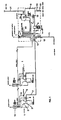
Figure 1 shows an apparatus according to the invention as a diagram. -
Figure 1 shows a transfer and collection system according to the invention for food waste as a diagram. The system comprises at least onefeed station 1, for example, for receiving food waste accumulating in a ship kitchen. There are typically many feed stations. The figure shows twofeed stations 1. In the following, only the operation of one feed station is described. In the embodiment of the figure, thefeed station 1 comprises afeed funnel 2, in connection with which, typically below it, is arranged a macerator 3 for grinding food waste. The form of the feed funnel is advantageously conical. In connection with thefeed funnel 2, also pieces of equipment 4, 5 for feeding water or other liquid to thefeed funnel 2 are arranged. Thefeed station 1 is connected to a transfer pipe 7 through which the grinded food waste, is transferred with apump device 8 from thefeed station 1 to acollecting tank 9. Thepump device 8 is arranged to the transfer pipe 7 between thefeed station 1 and thecollecting tank 9, in which case the transferred food waste passes through thepump 8 from thefeed station 1 to thecollecting tank 9. In connection with the feed station, afirst line valve 6 is arranged to the feed pipe 7, which valve is controlled so that, when transferring food waste, from the feed station, it is open, and when food waste is not transferred, it is closed. Typically, eachfeed station 1 has itsown line valve 6 in its vicinity. In connection with the feed station, alocal control unit 10 is arranged which unit communicates with amain control unit 20. The user of the feed station controls typically the operation of the feed station and typically also the whole apparatus by means of the local control unit. The user or, for example, an automatic timer starts thefeed station 1 when there is a suitable amount of waste material, such as food waste, In the feed funnel. Thecontrol units feed stations 1 may be located on decks located in different tiers. Thecollecting tank 9, thepump device 8 and themain control unit 20 are advantageously arranged as one assembly, advantageously as a module, which is described with a dash line in the figure. In the figure, the control units are connected to each other with a signal cable, but also other data-transmitting arrangements are possible. - In the figure, the
pump device 8 is arranged to the pipe system 7 between thefeed stations 1 and the collectingtank 9, typically in the vicinity of thecollecting tank 9. The pump achieves a vacuum to the pipe system to the suction side. Thepump 8 is advantageously a so-called lobe rotor pump. The pumping direction of the pump is reversed, so that thesame pump 8 is used for both transferring food waste to the collectingtank 9 and for emptying the collecting tank through anoutlet pipe 11. Thepump 8 is thus arranged to the pipe system 7 between the collecting tank and the outlet pipe. Theoutlet pipe 11 is thus typically connected to the pipe system 7 between thefeed stations 1 and thepump 8, typically in the vicinity of thepump device 8. The vacuum achieved by thepump 8 enables transferring food waste in the pipe system 7, even though the pipe system would sometimes run upwards or to various directions. In the figure, the pipe system 7 is described as a diagram, and the actual directions are not shown in the diagram, but are dependent on the target of application. - The collecting tank has advantageously a
second outlet pipe 14, for example, for emptying the collecting tank to another tank, such as a waste tank truck. The second outlet pipe is provided with avalve member 15. Thecollecting tank 9 has also a ventilatingpipe 21. - The system according to the figure operates in the following way. The food waste material to be transferred is placed in the
feed funnel 2, and the user activates an operation from thelocal control unit 10, for example, from a push button. Then, the macerator 3 starts up, and, with the liquid-adding equipment 4, 5, liquid is brought to the grinded material. After a set time, thevacuum pump 8 starts up, and thefirst line valve 6 opens, when the transfer of grinded waste material from thefeed station 1 starts. The food waste transfers from the feedingstation 1 along the feed pipe 7 to thecollecting tank 9. - From the collecting tank, the food waste is emptied by means of the
pump device 8 to theoutlet pipe 11. Then, thesecond line valve 12 is closed, and the outlet-line valve 13 is opened. Thepump device 8 is now arranged to operate in the reverse direction, most suitably by changing the rotation direction, when waste material, such as food waste, transfers from the collectingtank 9 to theoutlet pipe 11. The emptying of the collecting tank is performed, for example, on the basis of information given bylimit sensors - To the collecting tank is arranged a washing liquid fitting 18, especially a water fitting. Then, the washing of
tank 9 is combined to the emptying of the tank. As the surface reaches the lower limit surface when emptying the tank, the wash-fittingvalve 19 opens. When the tank is empty, thepump 8 stops. In connection with the washing of the tank, also the flushing of the pipe system, the pump and theoutlet line 11 is typically arranged. - The invention thus relates to a method for transferring and collecting food waste, in which method the food waste is transferred in the pipe system 7 portion-like from the
feed station 1 to thecollecting tank 9 and possibly onwards to further processing. Food waste is transferred in the pipe system with thepump device 8 which is arranged to the pipe system 7 between the feed station and the collecting tank, in which case the food waste passes through thepump 8. - According to an advantageous embodiment food waste is grinded, advantageously in the
feed unit 1, before transferring it to thecollecting tank 9. - To the food waste, liquid is added before transferring it from the
feed unit 1 to thecollecting tank 9. When transferring food waste, first thepump unit 8 is started up, and afirst line valve 6 possible at least in systems withmany feed stations 1 is opened, when the food waste, transfers from thefeed station 1 along the pipe 7 through thepump 8 to the collecting tank. - When transferring the food waste, to further processing or for removing it from the ship's
collecting tank 9 to theoutlet pipe 11, thesame pump device 8 is used for emptying by operating it in the reverse direction. - When transferring food waste to further processing from the collecting tank to the
outlet pipe 11, thesecond line valve 12 of the pipe system 7 is closed, theline valve 13 of theoutlet pipe 11 is opened, and the pump device is used in the reverse direction to accomplish the emptying of the food waste from the collectingtank 9. - An apparatus for transferring and collecting food waste which apparatus comprises at least one
feed station 1, collectingtank 9, pipe-system 7 between thefeed station 1 and thecollecting tank 9, andpump device 8 for food waste. It is characteristic for the invention that thepump device 8 is arranged to the pipe 7 between thefeed station 1 and thecollecting tank 9 so that food waste passes through thepump 8 to thecollecting tank 9 when transferring food waste from the feed station to the collecting tank. - According to an advantageous embodiment, the apparatus comprises an
outlet pipe 11 which is arranged to the pipe system 7 to the opposite side of thepump 8 with regards to thecollecting tank 9, and asecond line valve 12, in which case the collecting tank may be emptied through theoutlet pipe 11 by using thepump 8 in the reverse direction. - The
feed station 1 comprises, according to an advantageous embodiment, a macerator 3 for food waste. - According to an advantageous embodiment of the invention, the
pump device 8 is a pump achieving at least a partial vacuum in the suction side, most suitably a so-called lobe rotor pump. - At least in an apparatus comprising
many feed stations 1, aline valve 6 is arranged to the pipe system 7 for opening and closing the connection between eachfeed station 1 and thecollecting tank 9. - It is well known by those skilled in the art that the invention does not limit to the embodiments described above, but it may vary within the scope of the enclosed patent claims. If required, the characteristic features possibly described in this specification together with other characteristic features may also be used separate from each other.
Claims (9)
- A method for transferring and collecting food waste material in which method the waste material is transferred in a pipe system (7) portion-like from a feed station (1) to a collecting tank (9) and possibly onwards to further processing, and in which method the waste material is transferred in the pipe system with a pump device (8) which is arranged to the pipe system (7) between the feed station and the collecting tank, in which case the waste material passes through the pump (8), characterised in that at least a partial vacuum is achieved in the pipe system in the suction side of the pump device (8) and in that when transferring the waste material for further processing or removing it from the collecting tank (9) to an outlet pipe (11), the said pump device (8) is used by operating it in the reverse direction.
- A method according to claim 1, characterised in that the waste material is grinded, advantageously in the feed unit, before transferring it to the collecting tank (9).
- A method according to claim 1 or 2, characterised in that liquid is added to the waste material before transferring it from the feed unit (1) to the collecting tank (9).
- A method according to any one of claims 1-3, characterised by, when transferring waste material first starting up the pump unit (8), and opening a first in-line valve (6) possible at least in systems with many feed stations, when the waste material transfers from the feed station (1) along a pipe (7) through the pump (8) to the collecting tank.
- A method according to any one of claims 1-4, characterised by, when transferring the waste material to further processing from the collecting tank to the outlet pipe (11), closing a second line valve (12) of the pipe system (7), opening a line valve (13) of the outlet pipe (11), and using the pump device in the reverse direction to accomplish the emptying of the waste material from the collecting tank (9).
- An apparatus for transferring and collecting food waste material which apparatus comprises at least one feed station (1), collecting tank (9), pipe system (7) between the feed station (1) and the collecting tank (9), and pump device (8) for waste material in which the pump device (8) is arranged to a pipe (7) between the feed station (1) and the collecting tank (9) so that the waste material passes through the pump (8) to the collecting tank (9) when transferring waste material from the feed station to the collecting tank, characterised in that the pump device (8) is a pump achieving at least a partial vacuum in the suction side, and in that the apparatus comprises an outlet pipe (11) which is arranged to the pipe system (7) to the opposite side of the pump (8) with regards to the collecting tank, and a second line valve (12), in which case the collecting tank may be emptied through the outlet pipe (11) by using the pump (8) in the reverse direction.
- An apparatus according to claim 6, characterised in that the feed unit (1) comprises a macerator (3) for waste material, such as food waste.
- An apparatus according to claim 6 or 7, characterised in that the pump device (8) is a so-called lobe rotor pump.
- An apparatus according to any one of claims 6-8, characterised by arranging a line valve (6) to the pipe system (7) at least in an apparatus comprising many feed stations (1) for opening and closing the connection between each feed station (1) and the collecting tank (9).
Priority Applications (1)
| Application Number | Priority Date | Filing Date | Title |
|---|---|---|---|
| PL06075579T PL1702839T3 (en) | 2005-03-17 | 2006-03-10 | Method and apparatus for transferring and collecting waste material |
Applications Claiming Priority (1)
| Application Number | Priority Date | Filing Date | Title |
|---|---|---|---|
| FI20055122A FI121736B (en) | 2005-03-17 | 2005-03-17 | Method and facility for transport and collection of waste material |
Publications (2)
| Publication Number | Publication Date |
|---|---|
| EP1702839A1 EP1702839A1 (en) | 2006-09-20 |
| EP1702839B1 true EP1702839B1 (en) | 2011-01-26 |
Family
ID=34385143
Family Applications (1)
| Application Number | Title | Priority Date | Filing Date |
|---|---|---|---|
| EP20060075579 Not-in-force EP1702839B1 (en) | 2005-03-17 | 2006-03-10 | Method and apparatus for transferring and collecting waste material |
Country Status (9)
| Country | Link |
|---|---|
| US (2) | US7475835B2 (en) |
| EP (1) | EP1702839B1 (en) |
| AT (1) | ATE496822T1 (en) |
| DE (1) | DE602006019793D1 (en) |
| DK (1) | DK1702839T3 (en) |
| ES (1) | ES2357139T3 (en) |
| FI (1) | FI121736B (en) |
| PL (1) | PL1702839T3 (en) |
| PT (1) | PT1702839E (en) |
Families Citing this family (4)
| Publication number | Priority date | Publication date | Assignee | Title |
|---|---|---|---|---|
| AU2007202168A1 (en) * | 2007-05-15 | 2008-12-11 | Pioneer Waste Management Holdings Trust Pty Limited | Putrescible organic waste treatment |
| WO2011097556A1 (en) * | 2010-02-08 | 2011-08-11 | Lubrizol Advanced Materials, Inc. | Cpvc pipes, fittings and tubular conduits in marine vessels |
| FI122107B (en) * | 2010-02-18 | 2011-08-31 | Maricap Oy | Method and equipment in a pneumatic material transfer system |
| US20120285873A1 (en) * | 2011-05-10 | 2012-11-15 | Brenan John | Organic waste management system |
Family Cites Families (8)
| Publication number | Priority date | Publication date | Assignee | Title |
|---|---|---|---|---|
| FR2080786B1 (en) | 1970-02-26 | 1976-07-23 | Black Clawson Fibreclaim Inc | |
| US4054519A (en) * | 1975-09-04 | 1977-10-18 | Nautron Corporation | Hydraulic attrition unit for marine toilet |
| US4319366A (en) | 1980-02-07 | 1982-03-16 | Baker Jr Roupen | Waste storage apparatus |
| WO1983001267A1 (en) * | 1981-10-09 | 1983-04-14 | Mac Pherson, David, B. | Sewage treatment device |
| JPS59130764A (en) | 1983-01-14 | 1984-07-27 | Tokyo Tatsuno Co Ltd | Oil bleed-out device for car |
| US4819279A (en) * | 1987-09-28 | 1989-04-11 | Sealand Technology, Inc. | Vacuum toilet system |
| US5681148A (en) | 1995-10-31 | 1997-10-28 | Sealand Technology, Inc. | Vacuum/holding tank |
| JP2004050058A (en) | 2002-07-19 | 2004-02-19 | Aisin Seiki Co Ltd | Food waste treatment apparatus |
-
2005
- 2005-03-17 FI FI20055122A patent/FI121736B/en not_active IP Right Cessation
- 2005-03-18 US US11/084,074 patent/US7475835B2/en not_active Expired - Fee Related
-
2006
- 2006-03-10 ES ES06075579T patent/ES2357139T3/en active Active
- 2006-03-10 PT PT06075579T patent/PT1702839E/en unknown
- 2006-03-10 DK DK06075579T patent/DK1702839T3/en active
- 2006-03-10 AT AT06075579T patent/ATE496822T1/en active
- 2006-03-10 EP EP20060075579 patent/EP1702839B1/en not_active Not-in-force
- 2006-03-10 DE DE200660019793 patent/DE602006019793D1/en active Active
- 2006-03-10 PL PL06075579T patent/PL1702839T3/en unknown
-
2007
- 2007-04-20 US US11/788,848 patent/US20070295660A1/en not_active Abandoned
Also Published As
| Publication number | Publication date |
|---|---|
| FI121736B (en) | 2011-03-31 |
| US20060207653A1 (en) | 2006-09-21 |
| PL1702839T3 (en) | 2011-06-30 |
| FI20055122A (en) | 2006-09-18 |
| FI20055122A0 (en) | 2005-03-17 |
| DK1702839T3 (en) | 2011-05-09 |
| PT1702839E (en) | 2011-03-01 |
| US7475835B2 (en) | 2009-01-13 |
| US20070295660A1 (en) | 2007-12-27 |
| ES2357139T3 (en) | 2011-04-19 |
| DE602006019793D1 (en) | 2011-03-10 |
| EP1702839A1 (en) | 2006-09-20 |
| ATE496822T1 (en) | 2011-02-15 |
Similar Documents
| Publication | Publication Date | Title |
|---|---|---|
| EP1702839B1 (en) | Method and apparatus for transferring and collecting waste material | |
| US3780757A (en) | Waste disposal system and method | |
| US6638420B2 (en) | Apparatus for sewage treatment | |
| GB1574375A (en) | Removal of liquid solid and semi-solid wastes | |
| RU2444183C2 (en) | Mobile concentrating plant and method of milk concentration | |
| JPH09964A (en) | Garbage crushing and treating system | |
| US6009892A (en) | Device for disposal of liquid media | |
| CN201391751Y (en) | Energy dissipation device for undisturbed switch in operation mode of multistage pumping station | |
| CN216538844U (en) | Automatic particle size detection equipment and particle refining machine | |
| JPS633358Y2 (en) | ||
| EP2142449B1 (en) | Vacuum operated waste collection system | |
| CN106828788A (en) | Multi-functional waters cleaning boat is unloaded after preceding receipts | |
| CN219688223U (en) | Kitchen garbage conveying and loading device | |
| US3604449A (en) | Apparatus for unloading liquid storage tanks | |
| CN220976746U (en) | Ship domestic sewage collecting and treating device | |
| CN215878979U (en) | Cleaning equipment for high-pressure spray gun machine | |
| CN217780116U (en) | Material conveying device | |
| US3336930A (en) | Liquid unloading method and apparatus | |
| JPS616089A (en) | Discharge device of cleaning bilge in hold | |
| KR20160003432A (en) | Auto seperating oily water from bilge tank | |
| CN1978308A (en) | Caustic soda liquid discharge processand its special equipment | |
| CN115352578A (en) | Automatic loading, unloading and cargo joint debugging system for chemical tanker | |
| CN117049649A (en) | Multistage water treatment discharge system | |
| CN114715962A (en) | Design method of sewage treatment system on ship | |
| CN114227939A (en) | Pulping device suitable for multi-scene operation |
Legal Events
| Date | Code | Title | Description |
|---|---|---|---|
| PUAI | Public reference made under article 153(3) epc to a published international application that has entered the european phase |
Free format text: ORIGINAL CODE: 0009012 |
|
| AK | Designated contracting states |
Kind code of ref document: A1 Designated state(s): AT BE BG CH CY CZ DE DK EE ES FI FR GB GR HU IE IS IT LI LT LU LV MC NL PL PT RO SE SI SK TR |
|
| AX | Request for extension of the european patent |
Extension state: AL BA HR MK YU |
|
| 17P | Request for examination filed |
Effective date: 20070316 |
|
| 17Q | First examination report despatched |
Effective date: 20070420 |
|
| AKX | Designation fees paid |
Designated state(s): AT BE BG CH CY CZ DE DK EE ES FI FR GB GR HU IE IS IT LI LT LU LV MC NL PL PT RO SE SI SK TR |
|
| GRAP | Despatch of communication of intention to grant a patent |
Free format text: ORIGINAL CODE: EPIDOSNIGR1 |
|
| RAP1 | Party data changed (applicant data changed or rights of an application transferred) |
Owner name: MARIMATIC OY |
|
| GRAS | Grant fee paid |
Free format text: ORIGINAL CODE: EPIDOSNIGR3 |
|
| GRAA | (expected) grant |
Free format text: ORIGINAL CODE: 0009210 |
|
| AK | Designated contracting states |
Kind code of ref document: B1 Designated state(s): AT BE BG CH CY CZ DE DK EE ES FI FR GB GR HU IE IS IT LI LT LU LV MC NL PL PT RO SE SI SK TR |
|
| REG | Reference to a national code |
Ref country code: GB Ref legal event code: FG4D |
|
| REG | Reference to a national code |
Ref country code: CH Ref legal event code: EP |
|
| REG | Reference to a national code |
Ref country code: NL Ref legal event code: T3 |
|
| REG | Reference to a national code |
Ref country code: PT Ref legal event code: SC4A Free format text: AVAILABILITY OF NATIONAL TRANSLATION Effective date: 20110222 |
|
| REG | Reference to a national code |
Ref country code: IE Ref legal event code: FG4D |
|
| REF | Corresponds to: |
Ref document number: 602006019793 Country of ref document: DE Date of ref document: 20110310 Kind code of ref document: P |
|
| REG | Reference to a national code |
Ref country code: DE Ref legal event code: R096 Ref document number: 602006019793 Country of ref document: DE Effective date: 20110310 |
|
| REG | Reference to a national code |
Ref country code: ES Ref legal event code: FG2A Ref document number: 2357139 Country of ref document: ES Kind code of ref document: T3 Effective date: 20110419 |
|
| REG | Reference to a national code |
Ref country code: SE Ref legal event code: TRGR |
|
| REG | Reference to a national code |
Ref country code: DK Ref legal event code: T3 |
|
| REG | Reference to a national code |
Ref country code: GR Ref legal event code: EP Ref document number: 20110400587 Country of ref document: GR Effective date: 20110412 |
|
| LTIE | Lt: invalidation of european patent or patent extension |
Effective date: 20110126 |
|
| REG | Reference to a national code |
Ref country code: PL Ref legal event code: T3 |
|
| PG25 | Lapsed in a contracting state [announced via postgrant information from national office to epo] |
Ref country code: LT Free format text: LAPSE BECAUSE OF FAILURE TO SUBMIT A TRANSLATION OF THE DESCRIPTION OR TO PAY THE FEE WITHIN THE PRESCRIBED TIME-LIMIT Effective date: 20110126 Ref country code: IS Free format text: LAPSE BECAUSE OF FAILURE TO SUBMIT A TRANSLATION OF THE DESCRIPTION OR TO PAY THE FEE WITHIN THE PRESCRIBED TIME-LIMIT Effective date: 20110526 Ref country code: LV Free format text: LAPSE BECAUSE OF FAILURE TO SUBMIT A TRANSLATION OF THE DESCRIPTION OR TO PAY THE FEE WITHIN THE PRESCRIBED TIME-LIMIT Effective date: 20110126 |
|
| PG25 | Lapsed in a contracting state [announced via postgrant information from national office to epo] |
Ref country code: FI Free format text: LAPSE BECAUSE OF FAILURE TO SUBMIT A TRANSLATION OF THE DESCRIPTION OR TO PAY THE FEE WITHIN THE PRESCRIBED TIME-LIMIT Effective date: 20110126 Ref country code: BG Free format text: LAPSE BECAUSE OF FAILURE TO SUBMIT A TRANSLATION OF THE DESCRIPTION OR TO PAY THE FEE WITHIN THE PRESCRIBED TIME-LIMIT Effective date: 20110426 Ref country code: CY Free format text: LAPSE BECAUSE OF FAILURE TO SUBMIT A TRANSLATION OF THE DESCRIPTION OR TO PAY THE FEE WITHIN THE PRESCRIBED TIME-LIMIT Effective date: 20110126 Ref country code: SI Free format text: LAPSE BECAUSE OF FAILURE TO SUBMIT A TRANSLATION OF THE DESCRIPTION OR TO PAY THE FEE WITHIN THE PRESCRIBED TIME-LIMIT Effective date: 20110126 |
|
| REG | Reference to a national code |
Ref country code: HU Ref legal event code: AG4A Ref document number: E010952 Country of ref document: HU |
|
| PG25 | Lapsed in a contracting state [announced via postgrant information from national office to epo] |
Ref country code: MC Free format text: LAPSE BECAUSE OF NON-PAYMENT OF DUE FEES Effective date: 20110331 Ref country code: EE Free format text: LAPSE BECAUSE OF FAILURE TO SUBMIT A TRANSLATION OF THE DESCRIPTION OR TO PAY THE FEE WITHIN THE PRESCRIBED TIME-LIMIT Effective date: 20110126 |
|
| REG | Reference to a national code |
Ref country code: CH Ref legal event code: PL |
|
| PG25 | Lapsed in a contracting state [announced via postgrant information from national office to epo] |
Ref country code: SK Free format text: LAPSE BECAUSE OF FAILURE TO SUBMIT A TRANSLATION OF THE DESCRIPTION OR TO PAY THE FEE WITHIN THE PRESCRIBED TIME-LIMIT Effective date: 20110126 Ref country code: CZ Free format text: LAPSE BECAUSE OF FAILURE TO SUBMIT A TRANSLATION OF THE DESCRIPTION OR TO PAY THE FEE WITHIN THE PRESCRIBED TIME-LIMIT Effective date: 20110126 Ref country code: RO Free format text: LAPSE BECAUSE OF FAILURE TO SUBMIT A TRANSLATION OF THE DESCRIPTION OR TO PAY THE FEE WITHIN THE PRESCRIBED TIME-LIMIT Effective date: 20110126 |
|
| PLBE | No opposition filed within time limit |
Free format text: ORIGINAL CODE: 0009261 |
|
| STAA | Information on the status of an ep patent application or granted ep patent |
Free format text: STATUS: NO OPPOSITION FILED WITHIN TIME LIMIT |
|
| 26N | No opposition filed |
Effective date: 20111027 |
|
| REG | Reference to a national code |
Ref country code: IE Ref legal event code: MM4A |
|
| PG25 | Lapsed in a contracting state [announced via postgrant information from national office to epo] |
Ref country code: LI Free format text: LAPSE BECAUSE OF NON-PAYMENT OF DUE FEES Effective date: 20110331 Ref country code: CH Free format text: LAPSE BECAUSE OF NON-PAYMENT OF DUE FEES Effective date: 20110331 Ref country code: IE Free format text: LAPSE BECAUSE OF NON-PAYMENT OF DUE FEES Effective date: 20110310 |
|
| REG | Reference to a national code |
Ref country code: DE Ref legal event code: R097 Ref document number: 602006019793 Country of ref document: DE Effective date: 20111027 |
|
| PG25 | Lapsed in a contracting state [announced via postgrant information from national office to epo] |
Ref country code: LU Free format text: LAPSE BECAUSE OF NON-PAYMENT OF DUE FEES Effective date: 20110310 |
|
| REG | Reference to a national code |
Ref country code: FR Ref legal event code: PLFP Year of fee payment: 11 |
|
| REG | Reference to a national code |
Ref country code: FR Ref legal event code: PLFP Year of fee payment: 12 |
|
| PGFP | Annual fee paid to national office [announced via postgrant information from national office to epo] |
Ref country code: NL Payment date: 20170321 Year of fee payment: 12 Ref country code: GR Payment date: 20170314 Year of fee payment: 12 Ref country code: SE Payment date: 20170321 Year of fee payment: 12 Ref country code: FR Payment date: 20170322 Year of fee payment: 12 Ref country code: DE Payment date: 20170322 Year of fee payment: 12 |
|
| PGFP | Annual fee paid to national office [announced via postgrant information from national office to epo] |
Ref country code: PT Payment date: 20170308 Year of fee payment: 12 Ref country code: GB Payment date: 20170322 Year of fee payment: 12 Ref country code: DK Payment date: 20170321 Year of fee payment: 12 Ref country code: BE Payment date: 20170321 Year of fee payment: 12 Ref country code: AT Payment date: 20170322 Year of fee payment: 12 Ref country code: HU Payment date: 20170316 Year of fee payment: 12 Ref country code: PL Payment date: 20170221 Year of fee payment: 12 |
|
| PGFP | Annual fee paid to national office [announced via postgrant information from national office to epo] |
Ref country code: ES Payment date: 20170315 Year of fee payment: 12 Ref country code: TR Payment date: 20170217 Year of fee payment: 12 |
|
| PGFP | Annual fee paid to national office [announced via postgrant information from national office to epo] |
Ref country code: IT Payment date: 20170323 Year of fee payment: 12 |
|
| REG | Reference to a national code |
Ref country code: DE Ref legal event code: R119 Ref document number: 602006019793 Country of ref document: DE |
|
| REG | Reference to a national code |
Ref country code: DK Ref legal event code: EBP Effective date: 20180331 |
|
| PG25 | Lapsed in a contracting state [announced via postgrant information from national office to epo] |
Ref country code: PT Free format text: LAPSE BECAUSE OF NON-PAYMENT OF DUE FEES Effective date: 20180910 Ref country code: SE Free format text: LAPSE BECAUSE OF NON-PAYMENT OF DUE FEES Effective date: 20180311 |
|
| REG | Reference to a national code |
Ref country code: NL Ref legal event code: MM Effective date: 20180401 |
|
| REG | Reference to a national code |
Ref country code: AT Ref legal event code: MM01 Ref document number: 496822 Country of ref document: AT Kind code of ref document: T Effective date: 20180310 |
|
| GBPC | Gb: european patent ceased through non-payment of renewal fee |
Effective date: 20180310 |
|
| REG | Reference to a national code |
Ref country code: BE Ref legal event code: MM Effective date: 20180331 |
|
| PG25 | Lapsed in a contracting state [announced via postgrant information from national office to epo] |
Ref country code: NL Free format text: LAPSE BECAUSE OF NON-PAYMENT OF DUE FEES Effective date: 20180401 |
|
| PG25 | Lapsed in a contracting state [announced via postgrant information from national office to epo] |
Ref country code: DE Free format text: LAPSE BECAUSE OF NON-PAYMENT OF DUE FEES Effective date: 20181002 Ref country code: AT Free format text: LAPSE BECAUSE OF NON-PAYMENT OF DUE FEES Effective date: 20180310 Ref country code: GR Free format text: LAPSE BECAUSE OF NON-PAYMENT OF DUE FEES Effective date: 20181003 Ref country code: HU Free format text: LAPSE BECAUSE OF NON-PAYMENT OF DUE FEES Effective date: 20180311 |
|
| PG25 | Lapsed in a contracting state [announced via postgrant information from national office to epo] |
Ref country code: GB Free format text: LAPSE BECAUSE OF NON-PAYMENT OF DUE FEES Effective date: 20180310 Ref country code: IT Free format text: LAPSE BECAUSE OF NON-PAYMENT OF DUE FEES Effective date: 20180310 Ref country code: BE Free format text: LAPSE BECAUSE OF NON-PAYMENT OF DUE FEES Effective date: 20180331 |
|
| PG25 | Lapsed in a contracting state [announced via postgrant information from national office to epo] |
Ref country code: FR Free format text: LAPSE BECAUSE OF NON-PAYMENT OF DUE FEES Effective date: 20180331 |
|
| PG25 | Lapsed in a contracting state [announced via postgrant information from national office to epo] |
Ref country code: DK Free format text: LAPSE BECAUSE OF NON-PAYMENT OF DUE FEES Effective date: 20180331 |
|
| PG25 | Lapsed in a contracting state [announced via postgrant information from national office to epo] |
Ref country code: PL Free format text: LAPSE BECAUSE OF NON-PAYMENT OF DUE FEES Effective date: 20180310 |
|
| REG | Reference to a national code |
Ref country code: ES Ref legal event code: FD2A Effective date: 20190904 |
|
| PG25 | Lapsed in a contracting state [announced via postgrant information from national office to epo] |
Ref country code: ES Free format text: LAPSE BECAUSE OF NON-PAYMENT OF DUE FEES Effective date: 20180311 |
|
| PG25 | Lapsed in a contracting state [announced via postgrant information from national office to epo] |
Ref country code: TR Free format text: LAPSE BECAUSE OF NON-PAYMENT OF DUE FEES Effective date: 20180310 |