EP1702830A1 - Electric power steering device - Google Patents
Electric power steering device Download PDFInfo
- Publication number
- EP1702830A1 EP1702830A1 EP04820147A EP04820147A EP1702830A1 EP 1702830 A1 EP1702830 A1 EP 1702830A1 EP 04820147 A EP04820147 A EP 04820147A EP 04820147 A EP04820147 A EP 04820147A EP 1702830 A1 EP1702830 A1 EP 1702830A1
- Authority
- EP
- European Patent Office
- Prior art keywords
- equal
- gear
- tooth
- less
- motor
- Prior art date
- Legal status (The legal status is an assumption and is not a legal conclusion. Google has not performed a legal analysis and makes no representation as to the accuracy of the status listed.)
- Granted
Links
Images



Classifications
-
- B—PERFORMING OPERATIONS; TRANSPORTING
- B62—LAND VEHICLES FOR TRAVELLING OTHERWISE THAN ON RAILS
- B62D—MOTOR VEHICLES; TRAILERS
- B62D5/00—Power-assisted or power-driven steering
- B62D5/04—Power-assisted or power-driven steering electrical, e.g. using an electric servo-motor connected to, or forming part of, the steering gear
-
- B—PERFORMING OPERATIONS; TRANSPORTING
- B62—LAND VEHICLES FOR TRAVELLING OTHERWISE THAN ON RAILS
- B62D—MOTOR VEHICLES; TRAILERS
- B62D5/00—Power-assisted or power-driven steering
- B62D5/04—Power-assisted or power-driven steering electrical, e.g. using an electric servo-motor connected to, or forming part of, the steering gear
- B62D5/0409—Electric motor acting on the steering column
- B62D5/0412—Electric motor acting on the steering column the axes of motor and steering column being parallel
Definitions
- the present invention relates to a motor-driven power steering apparatus transmitting a rotating torque of an electric motor to a steering shaft by a drive gear provided in an output shaft of the electric motor and a driven gear provided in the steering shaft.
- a motor-driven power steering apparatus making good use of an electric motor is well employed as a steering assist mechanism.
- the motor-driven power steering apparatus transmits a rotating torque of the electric motor to a steering shaft via a worm gear.
- the transmission efficiency of the rotating torque becomes comparatively high such as about 95 %. Accordingly, it is possible to reduce the output torque of the electric motor at that degree, and it is possible to make the entire of the steering apparatus compact by suppressing an enlargement of an outer shape of the electric motor.
- Japanese Patent Application Laid-Open No. 11-124045 discloses a motor-driven power steering apparatus in which an entire of a steering apparatus having an electric motor and a speed reducer arranged therein can be made compact by accommodating a speed reducer constituted by a pair of spur gears or helical gears having a high speed reduction ratio within a housing, and arranging the electric motor close to the housing in which a steering shaft is accommodated.
- the present invention is made by taking the circumstance mentioned above into consideration, and an object of the present invention is to provide a motor-driven power steering apparatus which can achieve a predetermined speed reduction ratio even in the case that the motor-driven power steering apparatus is constituted by a pair of spur gears or helical gears, and can secure a sufficient gear strength on the basis of a simple structure.
- a motor-driven power steering apparatus in which a rotating torque of an electric motor is transmitted to a steering shaft by a drive gear provided in an output shaft of the electric motor and a driven gear provided in the steering shaft, and a speed reduction ratio is equal to or more than 3, wherein the steering shaft and the output shaft of the electric motor are arranged in almost parallel, a center distance between both the shafts is equal to or more than 35 mm and equal to or less than 90 mm, and the drive gear is configured such that a number of teeth is equal to or more than 6 and equal to or less than 15, a module is equal to or more than 0.8 and equal to or less than 1.5, a tooth depth is equal to or less than 2.4 times of the module, and a pressure angle is equal to or more than 14.5 degrees and equal to or less than 30 degrees, and a torsion angle is equal to or more than 0 degrees and equal to or less than 40 degrees.
- a motor-driven power steering apparatus as recited in the first aspect, wherein an involute gear in which a tooth profile is configured in such a manner that a pressure angle is increased from a tooth top of the gear to a tooth root is employed for one or both of the drive gear and the driven gear.
- the motor-driven power steering apparatus in accordance with the second aspect of the present invention, it is possible to reduce a tooth root stress at a time when a maximum torque is applied, by employing the involute gear in which the tooth profile is formed in such a manner that the pressure angle is increased from the tooth top of the gear to the tooth root, and it is possible to secure a durability of the gear.
- a motor-driven power steering apparatus as recited in the first or second aspect, wherein an involute gear in which a crowning process is applied in a direction of a tooth trace is employed for one or both of the drive gear and the driven gear.
- the involute gear in which the crowning process is applied in the direction of the tooth trace is employed, the tooth surface stress can be reduced. Accordingly, even in the case that a continuous operation is executed under a rated load condition, it is possible to secure a durability of the gear.
- FIG. 1 is a cross sectional view showing a schematic structure of a motor-driven power steering apparatus in accordance with an embodiment of the present invention.
- the structure is made such that a steering torque acting on a steering member 4 is transmitted to a steered wheel side via a steering shaft constituted by an input shaft 12, a torsion bar 13 and an output shaft 14, and a rotating torque of an electric motor 7 is transmitted to the steered wheel side via a speed reducer 1 constituted by a small gear (a drive gear) 6 and a large gear (a driven gear) 5, and the output shaft 14 of the steering shaft.
- the input shaft 12 is coupled to the steering member 4, and corresponds to one constituting element of a torque transmission means for transmitting the steering torque acting on the steering member 4 to the steered wheel side.
- the input shaft 12 is configured such that one end side is supported via a bearing (not shown), and the other end side is coupled to the torsion bar 13.
- the torsion bar 13 couples the input shaft 12 and the output shaft 14, and generates a torsional deformation on the basis of the steering torque, thereby generating a relative displacement of rotating angle between the input shaft 12 and the output shaft 14.
- the output shaft 14 is configured such that one end side is supported via bearings 11, 11, ..., and the other end side is coupled to the torsion bar 13.
- the output shaft 14 transmits the steering torque from the torsion bar 13 to the steered wheel side, and transmits the rotating torque of the electric motor 7 transmitted from the speed reducer 1 to the steered wheel side. Accordingly, the input shaft 12 and the output shaft 14 are elastically and relatively rotated in correspondence to the steering torque and are coaxially coupled.
- a torque detecting mechanism 15 is configured such as to detect the relative displacement of rotating angle between the output shaft 14 and the input shaft 12 generated due to the torsion of the torsion bar 13 by the steering torque, thereby detecting the steering torque.
- the speed reducer 1 is configured by a spur gear or a helical gear which is provided with the large gear 5 provided in the output shaft 14 of the steering shaft, and the small gear 6 provided in the output shaft of the electric motor 7. It is possible to arrange the electric motor 7 in almost parallel to the steering shaft, by employing the spur gear or the helical gear. However, a physical restriction on a layout is generated in an outside dimension of the electric motor 7 in correspondence to a center distance L between the steering shaft and the output shaft of the electric motor 7.
- the maximum allowable outside dimension of the electric motor 7 is constituted by a diameter 73 mm and a height 95 mm
- a rating torque is set to 4 Nm
- the center distance L is set to 55 mm
- a speed reduction ratio is set to about 10.
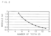
- FIG. 2 is a view showing a relation between a number of teeth Z of the small gear 6 and a module m of the small gear 6 in the case that the center distance L between the steering shaft and the output shaft of the electric motor 7 is set to 55 mm, the speed reduction ratio is set to 10, and a torsion angle ⁇ is set to 25 degrees.
- FIG. 3 is a view showing a relation among the pressure angle ⁇ of the small gear 6, the trochoid interference clearance and the tooth width of the tooth top in the case that the number of teeth Z is 10, the module m is 0.95 and a tooth depth h is 2.25 times of the module m.
- a circle mark indicates a trochoid interference clearance
- a rectangle mark indicates a value obtained by dividing the tooth thickness of the tooth top by the module value, respectively.
- the trochoid interference clearance equal to or more than 0.2 mm is necessary.
- the pressure angle ⁇ is equal to or more than 14.5 degrees and equal to ore less than 35 degrees which is defined as a standard value in Japanese Industrial Standards (JIS)
- the trochoid interference clearance becomes equal to or more than 0.2 mm in a region where the pressure angle ⁇ is equal to or more than 23 degrees. Accordingly, the trochoid interference is not generated.
- the tooth thickness of the tooth top equal to or more than 0.3 times of the module m is necessary. As shown in FIG.
- the pressure angle ⁇ in order to secure the tooth thickness of the tooth top equal to or more than 0.3 times of the module m, it is necessary to set the pressure angle ⁇ to be equal to or less than 27 degrees. In this case, the practical range exists in the torsion angle ⁇ equal to or more than 0 degrees and equal to or less than 40 degrees.
- reference symbol E denotes a longitudinal elastic modulus of a material (a steel material in the present embodiment) of the gear
- reference symbol ⁇ s denotes a front surface contact ratio
- reference symbol b denotes a tooth width of the small gear 6
- reference symbol d b denotes a mating pitch circle diameter of the small gear 6
- reference symbol ⁇ b denotes a mating pressure angle of the small gear 6
- reference symbol ⁇ g denotes a torsion angle of a base cylinder of the small gear 6
- reference symbol Z 1 denotes a number of teeth of the small gear 6
- reference symbol Z 2 denotes a number of teeth of the large gear 5
- reference symbol N b denotes an availability of the tooth width, respectively.
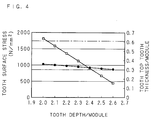
- FIG. 4 is a view showing a relation of the tooth surface stress ⁇ s and the tooth thickness of the tooth top with respect to the tooth depth h of the small gear 6, in the case of setting E to 206000 N/mm 2 , P n to 946, N b to 14 mm, Z 1 to 10, Z 2 to 97, m to 0.95, the pressure angle ⁇ to 25 degrees, the torsion angle ⁇ to 25 degrees, d b to 10.308 mm, ⁇ b to 25.283 degrees, ⁇ g to 22.521 degrees, and Nb to 0.995.
- a circle mark indicates a tooth surface stress
- a rectangle mark indicates a value obtained by dividing the tooth thickness of the tooth top by the module value, respectively.
- FIG. 5 is an explanatory view of a tooth surface shape of the speed reducer 1 used for the motor-driven power steering apparatus in accordance with the embodiment of the present invention.
- the tooth surface shape of any one of the large gear 5 and the small gear 6, or the tooth surface shapes of both of a pair of gears are formed by an aspect shown in FIG. 5.
- the tooth surface of the small gear 6 is shown by being divided into vertical and horizontal meshes.
- the tooth profile direction is provided with a negative pressure angle error in such a manner that the pressure angle of the tooth top becomes larger than the pressure angle of the tooth boot, and the tooth surface shape is formed in such a direction that the mutual mating stresses are increased, that is, such that the center portion forms convex.
- a crowning process is applied in a tooth trace direction, and the tooth surface shape is formed such that the center portion forms convex in the tooth trace direction.
Landscapes
- Engineering & Computer Science (AREA)
- Chemical & Material Sciences (AREA)
- Combustion & Propulsion (AREA)
- Transportation (AREA)
- Mechanical Engineering (AREA)
- Gear Transmission (AREA)
- Power Steering Mechanism (AREA)
- Gears, Cams (AREA)
Abstract
Description
- The present invention relates to a motor-driven power steering apparatus transmitting a rotating torque of an electric motor to a steering shaft by a drive gear provided in an output shaft of the electric motor and a driven gear provided in the steering shaft.
- In a steering apparatus for a motor vehicle in recent days, a motor-driven power steering apparatus making good use of an electric motor is well employed as a steering assist mechanism. The motor-driven power steering apparatus transmits a rotating torque of the electric motor to a steering shaft via a worm gear.
- However, in the worm gear, since a transmission efficiency of the rotating torque is comparatively low such as 60 to 80 %, in the case that a speed reduction ratio is set constant, an electric motor having a larger output torque is necessary for transmitting a predetermined rotating torque. Accordingly, there is a problem that an outer diameter of the electric motor becomes large and it is hard to make an entire of the steering apparatus compact. Therefore, there has been designed a speed reducer in which the output shaft of the electric motor is attached in such a manner as to be in almost parallel to the steering shaft, and which uses a spur gear or a helical gear in which the transmission efficiency of the rotating torque is comparatively high.
- In the case of using the spur gear or the helical gear for the speed reducer, the transmission efficiency of the rotating torque becomes comparatively high such as about 95 %. Accordingly, it is possible to reduce the output torque of the electric motor at that degree, and it is possible to make the entire of the steering apparatus compact by suppressing an enlargement of an outer shape of the electric motor.
- However, in the case of employing the speed reducer, for example, using the spur gear, if it is intended to obtain a necessary speed reduction ratio on the basis of a one-stage structure of the gear provided in the output shaft of the electric motor, and the gear attached to the steering shaft engaging with the gear, a pitch circle of the steering shaft side gear becomes large, and it is impossible to improve the condition that it is hard to intend to make the entire of the steering apparatus compact.
- On the other hand, in the case of employing a speed reducer having a multi-stage structure, for example, having intermediate gears, in place of the speed reducer having the one-stage structure, as the speed reducer using the spur gear, it is possible to intend to make the entire of the steering apparatus compact, however, there is generated a new problem that a comfortable steering feeling is reduced due to an increase of a backlash, a cost increase due to a complication of the structure of the speed reducer or the like.
- In order to solve the problem mentioned above, for example,
Japanese Patent Application Laid-Open No. 11-124045 - In the motor-driven power steering apparatus disclosed in the
Japanese Patent Application Laid-Open No. 11-124045 - However, it is hard in structure to actually manufacture the tooth profile based on the special theory disclosed in the
Japanese Patent Application Laid-Open No. 11-124045 - The present invention is made by taking the circumstance mentioned above into consideration, and an object of the present invention is to provide a motor-driven power steering apparatus which can achieve a predetermined speed reduction ratio even in the case that the motor-driven power steering apparatus is constituted by a pair of spur gears or helical gears, and can secure a sufficient gear strength on the basis of a simple structure.
- In order to achieve the object mentioned above, in accordance with a first aspect of the present invention, there is provided a motor-driven power steering apparatus in which a rotating torque of an electric motor is transmitted to a steering shaft by a drive gear provided in an output shaft of the electric motor and a driven gear provided in the steering shaft, and a speed reduction ratio is equal to or more than 3, wherein the steering shaft and the output shaft of the electric motor are arranged in almost parallel, a center distance between both the shafts is equal to or more than 35 mm and equal to or less than 90 mm, and the drive gear is configured such that a number of teeth is equal to or more than 6 and equal to or less than 15, a module is equal to or more than 0.8 and equal to or less than 1.5, a tooth depth is equal to or less than 2.4 times of the module, and a pressure angle is equal to or more than 14.5 degrees and equal to or less than 30 degrees, and a torsion angle is equal to or more than 0 degrees and equal to or less than 40 degrees.
- In the motor-driven power steering apparatus in accordance with the first aspect of the present invention, since there is employed a pair of gears in which steering shaft and the output shaft of the electric motor are in almost parallel, a transmission efficiency of the rotating torque is high, and it is possible to arrange the entire of steering apparatus compact. Further, on the basis of the data dimensions mentioned above, even in the case of using the gear which can be manufactured in the normal manufacturing step without using the tooth profile based on the predetermined special theory, it is possible to secure correct values of a trochoid interference clearance, a tooth thickness of a tooth top and a tooth surface stress.
- Further, in accordance with a second aspect of the present invention, there is provided a motor-driven power steering apparatus as recited in the first aspect, wherein an involute gear in which a tooth profile is configured in such a manner that a pressure angle is increased from a tooth top of the gear to a tooth root is employed for one or both of the drive gear and the driven gear.
- In the motor-driven power steering apparatus in accordance with the second aspect of the present invention, it is possible to reduce a tooth root stress at a time when a maximum torque is applied, by employing the involute gear in which the tooth profile is formed in such a manner that the pressure angle is increased from the tooth top of the gear to the tooth root, and it is possible to secure a durability of the gear.
- Further, in accordance with a third aspect of the present invention, there is provided a motor-driven power steering apparatus as recited in the first or second aspect, wherein an involute gear in which a crowning process is applied in a direction of a tooth trace is employed for one or both of the drive gear and the driven gear.
- In the motor-driven power steering apparatus in accordance with the third aspect of the present invention, since the involute gear in which the crowning process is applied in the direction of the tooth trace is employed, the tooth surface stress can be reduced. Accordingly, even in the case that a continuous operation is executed under a rated load condition, it is possible to secure a durability of the gear.
- In accordance with the present invention, since there is employed a pair of gears in which the steering shaft and the output shaft of the electric motor are in almost parallel, it is possible to obtain the motor-driven power steering apparatus in which the transmission efficiency of the rotating torque is high, and which is arranged compact as a whole. Further, on the basis of the data dimensions mentioned above, it is possible to secure the correct values of the trochoid interference clearance, the tooth thickness of the tooth top and the tooth surface stress, without employing the tooth profile based on the predetermined special theory.
-
- FIG. 1 is a cross sectional view showing a schematic structure of a motor-driven power steering apparatus in accordance with an embodiment of the present invention;
- FIG. 2 is a view showing a relation between a number of teeth of a small gear and a module of the small gear;
- FIG. 3 is a view showing a relation among a pressure angle, a trochoid interference clearance of the small gear, and a tooth thickness of a tooth top;
- FIG. 4 is a view showing a relation between a tooth surface stress with respect to a tooth depth of the small gear and a tooth thickness of the tooth top; and
- FIG. 5 is an explanatory view of a tooth surface shape of a speed reducer used in the motor-driven power steering apparatus in accordance with the embodiment of the present invention.
-
- 1
- speed reducer
- 5
- large gear (driven gear)
- 6
- small gear (drive gear)
- 7
- electric motor
- h
- tooth depth
- m
- module
- L
- center distance
- Z
- number of teeth
- α
- pressure angle
- FIG. 1 is a cross sectional view showing a schematic structure of a motor-driven power steering apparatus in accordance with an embodiment of the present invention. As shown in FIG. 1, the structure is made such that a steering torque acting on a steering member 4 is transmitted to a steered wheel side via a steering shaft constituted by an
input shaft 12, atorsion bar 13 and anoutput shaft 14, and a rotating torque of an electric motor 7 is transmitted to the steered wheel side via aspeed reducer 1 constituted by a small gear (a drive gear) 6 and a large gear (a driven gear) 5, and theoutput shaft 14 of the steering shaft. - The
input shaft 12 is coupled to the steering member 4, and corresponds to one constituting element of a torque transmission means for transmitting the steering torque acting on the steering member 4 to the steered wheel side. Theinput shaft 12 is configured such that one end side is supported via a bearing (not shown), and the other end side is coupled to thetorsion bar 13. - The
torsion bar 13 couples theinput shaft 12 and theoutput shaft 14, and generates a torsional deformation on the basis of the steering torque, thereby generating a relative displacement of rotating angle between theinput shaft 12 and theoutput shaft 14. - The
output shaft 14 is configured such that one end side is supported viabearings torsion bar 13. Theoutput shaft 14 transmits the steering torque from thetorsion bar 13 to the steered wheel side, and transmits the rotating torque of the electric motor 7 transmitted from thespeed reducer 1 to the steered wheel side. Accordingly, theinput shaft 12 and theoutput shaft 14 are elastically and relatively rotated in correspondence to the steering torque and are coaxially coupled. - A
torque detecting mechanism 15 is configured such as to detect the relative displacement of rotating angle between theoutput shaft 14 and theinput shaft 12 generated due to the torsion of thetorsion bar 13 by the steering torque, thereby detecting the steering torque. - The
speed reducer 1 is configured by a spur gear or a helical gear which is provided with thelarge gear 5 provided in theoutput shaft 14 of the steering shaft, and thesmall gear 6 provided in the output shaft of the electric motor 7. It is possible to arrange the electric motor 7 in almost parallel to the steering shaft, by employing the spur gear or the helical gear. However, a physical restriction on a layout is generated in an outside dimension of the electric motor 7 in correspondence to a center distance L between the steering shaft and the output shaft of the electric motor 7. For example, in the case that the maximum allowable outside dimension of the electric motor 7 is constituted by a diameter 73 mm and a height 95 mm, on the basis of the restriction on the layout, in order to secure a rotating torque equal to or more than 35 Nm for a steering assist torque around the steering shaft, a rating torque is set to 4 Nm, the center distance L is set to 55 mm, and a speed reduction ratio is set to about 10. - FIG. 2 is a view showing a relation between a number of teeth Z of the
small gear 6 and a module m of thesmall gear 6 in the case that the center distance L between the steering shaft and the output shaft of the electric motor 7 is set to 55 mm, the speed reduction ratio is set to 10, and a torsion angle β is set to 25 degrees. A diameter d (= Z x m) of a pitch circle of thesmall gear 6 is about 8 to 10 mm, however, in order to avoid a condition that the number of teeth is extremely large or extremely small, a practical range exists in the number of teeth Z equal to or more than 6 and equal to or less than 15, and the module m equal to or more than 0.8 and equal to or less than 1.5. - Next, taking into consideration a manufacturing error of the gear, and an elastic deformation of the tooth of the gear in the case of executing the rated load operation, a pressure angle α setting a trochoid interference clearance and a tooth thickness of a tooth top to correct values is selected. FIG. 3 is a view showing a relation among the pressure angle α of the
small gear 6, the trochoid interference clearance and the tooth width of the tooth top in the case that the number of teeth Z is 10, the module m is 0.95 and a tooth depth h is 2.25 times of the module m. In FIg. 3, a circle mark indicates a trochoid interference clearance, and a rectangle mark indicates a value obtained by dividing the tooth thickness of the tooth top by the module value, respectively. - In order to avoid the trochoid interference from being generated, the trochoid interference clearance equal to or more than 0.2 mm is necessary. As shown in FIg. 3, in the case that the pressure angle α is equal to or more than 14.5 degrees and equal to ore less than 35 degrees which is defined as a standard value in Japanese Industrial Standards (JIS), the trochoid interference clearance becomes equal to or more than 0.2 mm in a region where the pressure angle α is equal to or more than 23 degrees. Accordingly, the trochoid interference is not generated. On the other hand, in order to secure a tooth top strength, the tooth thickness of the tooth top equal to or more than 0.3 times of the module m is necessary. As shown in FIG. 3, in order to secure the tooth thickness of the tooth top equal to or more than 0.3 times of the module m, it is necessary to set the pressure angle α to be equal to or less than 27 degrees. In this case, the practical range exists in the torsion angle β equal to or more than 0 degrees and equal to or less than 40 degrees.
- Further, in the case that a steel material is employed as a material of the
small gear 6 and thelarge gear 5, it is possible to approximately determine a tooth surface stress σH with respect to a tangential load Pn in a perpendicular direction to the tooth of thesmall gear 6 generated on the basis of an auxiliary rotating torque by using (numerical expression 1).
- In this case, in (numeral expression 1), reference symbol E denotes a longitudinal elastic modulus of a material (a steel material in the present embodiment) of the gear, reference symbol εs denotes a front surface contact ratio, reference symbol b denotes a tooth width of the
small gear 6, reference symbol db denotes a mating pitch circle diameter of thesmall gear 6, reference symbol αb denotes a mating pressure angle of thesmall gear 6, reference symbol βg denotes a torsion angle of a base cylinder of thesmall gear 6, reference symbol Z1 denotes a number of teeth of thesmall gear 6, reference symbol Z2 denotes a number of teeth of thelarge gear 5, and reference symbol Nb denotes an availability of the tooth width, respectively. - FIG. 4 is a view showing a relation of the tooth surface stress σs and the tooth thickness of the tooth top with respect to the tooth depth h of the
small gear 6, in the case of setting E to 206000 N/mm2, Pn to 946, Nb to 14 mm, Z1 to 10, Z2 to 97, m to 0.95, the pressure angle α to 25 degrees, the torsion angle β to 25 degrees, db to 10.308 mm, αb to 25.283 degrees, βg to 22.521 degrees, and Nb to 0.995. In FIG. 4, a circle mark indicates a tooth surface stress, and a rectangle mark indicates a value obtained by dividing the tooth thickness of the tooth top by the module value, respectively. - In the case of setting a target value of the tooth surface stress σH to a threshold value 1760 N/m2 or less on design of a power transmission system gear of a motor vehicle, and setting a target value of the tooth thickness of the tooth top to 0.3 times of the module m or more, it is possible to satisfy both the conditions in the case that the tooth depth h is set to equal to or less than 2.4 times of the module m, as is apparent from FIG. 4.
- FIG. 5 is an explanatory view of a tooth surface shape of the
speed reducer 1 used for the motor-driven power steering apparatus in accordance with the embodiment of the present invention. In order to compensate for the reduction of the tooth root strength, the tooth surface shape of any one of thelarge gear 5 and thesmall gear 6, or the tooth surface shapes of both of a pair of gears are formed by an aspect shown in FIG. 5. In FIG. 5, the tooth surface of thesmall gear 6 is shown by being divided into vertical and horizontal meshes. The tooth profile direction is provided with a negative pressure angle error in such a manner that the pressure angle of the tooth top becomes larger than the pressure angle of the tooth boot, and the tooth surface shape is formed in such a direction that the mutual mating stresses are increased, that is, such that the center portion forms convex. Further, a crowning process is applied in a tooth trace direction, and the tooth surface shape is formed such that the center portion forms convex in the tooth trace direction. - It is possible to equalize a distribution of the contact stress in the tooth surface of the
small gear 6 used in thespeed reducer 1 in the tooth profile direction and the tooth trace direction by employing the tooth surface shape mentioned above, and it is possible to compensate for the lack of the tooth root strength while preventing a biased abrasion of the tooth surface, thereby contributing to an improvement of a durability
Claims (3)
- A motor-driven power steering apparatus in which a rotating torque of an electric motor is transmitted to a steering shaft by a drive gear provided in an output shaft of said electric motor and a driven gear provided in said steering shaft, and a speed reduction ratio is equal to or more than 3, wherein
said steering shaft and the output shaft of said electric motor are arranged in almost parallel, a center distance between both the shafts is equal to or more than 35 mm and equal to or less than 90 mm, and
said drive gear is configured such that a number of teeth is equal to or more than 6 and equal to or less than 15, a module is equal to or more than 0.8 and equal to or less than 1.5, a tooth depth is equal to or less than 2.4 times of the module, and a pressure angle is equal to or more than 14.5 degrees and equal to or less than 30 degrees, and a torsion angle is equal to or more than 0 degree and equal to or less than 40 degrees. - A motor-driven power steering apparatus as claimed in claim 1, wherein an involute gear in which a tooth profile is formed in such a manner that a pressure angle is increased from a tooth top of the gear to a tooth root is employed for one or both of said drive gear and said driven gear.
- A motor-driven power steering apparatus as claimed in claim 1 or 2, wherein an involute gear in which a crowning process is applied in a direction of a tooth trace is employed for one or both of said drive gear and said driven gear.
Applications Claiming Priority (2)
| Application Number | Priority Date | Filing Date | Title |
|---|---|---|---|
| JP2003409449 | 2003-12-08 | ||
| PCT/JP2004/017790 WO2005056367A1 (en) | 2003-12-08 | 2004-11-30 | Electric power steering device |
Publications (3)
| Publication Number | Publication Date |
|---|---|
| EP1702830A1 true EP1702830A1 (en) | 2006-09-20 |
| EP1702830A4 EP1702830A4 (en) | 2007-07-18 |
| EP1702830B1 EP1702830B1 (en) | 2010-09-22 |
Family
ID=34674898
Family Applications (1)
| Application Number | Title | Priority Date | Filing Date |
|---|---|---|---|
| EP04820147A Expired - Lifetime EP1702830B1 (en) | 2003-12-08 | 2004-11-30 | Electric power steering device |
Country Status (6)
| Country | Link |
|---|---|
| US (1) | US7600602B2 (en) |
| EP (1) | EP1702830B1 (en) |
| JP (1) | JPWO2005056367A1 (en) |
| KR (1) | KR20060103542A (en) |
| DE (1) | DE602004029282D1 (en) |
| WO (1) | WO2005056367A1 (en) |
Families Citing this family (5)
| Publication number | Priority date | Publication date | Assignee | Title |
|---|---|---|---|---|
| JP4419574B2 (en) | 2004-01-13 | 2010-02-24 | 株式会社ジェイテクト | Rack and pinion type steering device |
| DE102011087163A1 (en) * | 2011-11-28 | 2013-05-29 | Zf Friedrichshafen Ag | Transmission of a motor vehicle with PTO |
| BR112014013577A2 (en) * | 2011-12-06 | 2017-06-13 | Honda Motor Co Ltd | spiral gear mechanism |
| US9789900B2 (en) * | 2015-12-30 | 2017-10-17 | Automotive Research & Testing Center | Modular steering system |
| US10793183B2 (en) * | 2017-12-22 | 2020-10-06 | Trw Automotive U.S. Llc | Torque overlay steering apparatus |
Family Cites Families (8)
| Publication number | Priority date | Publication date | Assignee | Title |
|---|---|---|---|---|
| JPS6346281U (en) * | 1986-09-16 | 1988-03-29 | ||
| US5010970A (en) | 1988-05-27 | 1991-04-30 | Mazda Motor Corporation | Power-assisted steering system |
| DE4101810A1 (en) * | 1991-01-23 | 1992-07-30 | Teves Gmbh Alfred | Auxiliary electrochemical power steering - has electric servomotor for steering column housed in passenger compartment to protect from dirt, oil, petrol, etc. |
| US5341699A (en) | 1993-04-06 | 1994-08-30 | Axicon Gear Company | Zero dynamic increment gearing |
| JPH09263250A (en) | 1996-03-28 | 1997-10-07 | Fuji Kiko Co Ltd | Electric power steering device |
| JP2000130560A (en) * | 1998-10-27 | 2000-05-12 | Fuji Kiko Co Ltd | Cycloid gear with few teeth |
| JP2001133343A (en) * | 1999-11-05 | 2001-05-18 | Fuji Kiko Co Ltd | Electric power steering device |
| JP2001271889A (en) * | 2000-03-28 | 2001-10-05 | Juken Kogyo:Kk | Structure of a pair of involute gears |
-
2004
- 2004-11-30 US US10/596,285 patent/US7600602B2/en not_active Expired - Fee Related
- 2004-11-30 KR KR1020067013397A patent/KR20060103542A/en not_active Withdrawn
- 2004-11-30 EP EP04820147A patent/EP1702830B1/en not_active Expired - Lifetime
- 2004-11-30 WO PCT/JP2004/017790 patent/WO2005056367A1/en not_active Ceased
- 2004-11-30 DE DE602004029282T patent/DE602004029282D1/en not_active Expired - Lifetime
- 2004-11-30 JP JP2005516093A patent/JPWO2005056367A1/en active Pending
Also Published As
| Publication number | Publication date |
|---|---|
| DE602004029282D1 (en) | 2010-11-04 |
| US20070170787A1 (en) | 2007-07-26 |
| EP1702830B1 (en) | 2010-09-22 |
| WO2005056367A1 (en) | 2005-06-23 |
| KR20060103542A (en) | 2006-10-02 |
| EP1702830A4 (en) | 2007-07-18 |
| JPWO2005056367A1 (en) | 2007-12-06 |
| US7600602B2 (en) | 2009-10-13 |
Similar Documents
| Publication | Publication Date | Title |
|---|---|---|
| EP1731799B1 (en) | Rack and pinion-type steering device | |
| EP1747968B1 (en) | Method of manufacturing electric power steering device | |
| US9550243B2 (en) | Gear and manufacturing method for the same | |
| EP0520072A1 (en) | Planetary gearing | |
| EP3826151A1 (en) | Planetary reduction electrical machine capable of achieving full closed-loop control and articulated robot | |
| CN101713447B (en) | Gear pair consisting of a crown gear and of a pinion gear, differential compensation transmission device | |
| EP1702830B1 (en) | Electric power steering device | |
| US8100028B2 (en) | Cornu's spiral tooth gear | |
| US9512898B2 (en) | Worm gear mechanism | |
| Lee | Manufacturing process for a cylindrical crown gear drive with a controllable fourth order polynomial function of transmission error | |
| CN113415338B (en) | Steering-by-wire road sensing feedback device | |
| JP4746907B2 (en) | Planetary gear reducer | |
| EP0575431B1 (en) | Anti-roll mechanism for a rack and pinion | |
| KR20060030466A (en) | Belt Reduction Device and Electric Power Steering Device for Electric Power Steering System | |
| EP1887254B1 (en) | Electric power steering apparatus | |
| JP4517285B2 (en) | Electric power steering device | |
| EP1626205A1 (en) | Composite planetary device | |
| JP5273460B2 (en) | Steering mechanism design method | |
| US20040134300A1 (en) | Power-assisted steering having a gear mechanism | |
| JP2001133343A (en) | Electric power steering device | |
| Chang et al. | Tooth flank corrections of wide face width helical gears that account for shaft deflections | |
| US7798283B2 (en) | Driving device for power steering | |
| JP2012117649A (en) | Reduction gear, electric power steering device equipped with the same, and method of manufacturing reduction gear | |
| JP2006090481A (en) | Spiral gear, method for manufacturing the same, and method for manufacturing the driving body | |
| CN116395020A (en) | Steering mechanism and steering system with such a steering mechanism |
Legal Events
| Date | Code | Title | Description |
|---|---|---|---|
| PUAI | Public reference made under article 153(3) epc to a published international application that has entered the european phase |
Free format text: ORIGINAL CODE: 0009012 |
|
| 17P | Request for examination filed |
Effective date: 20060710 |
|
| AK | Designated contracting states |
Kind code of ref document: A1 Designated state(s): DE FR GB |
|
| DAX | Request for extension of the european patent (deleted) | ||
| RBV | Designated contracting states (corrected) |
Designated state(s): DE FR GB |
|
| A4 | Supplementary search report drawn up and despatched |
Effective date: 20070618 |
|
| 17Q | First examination report despatched |
Effective date: 20091210 |
|
| GRAP | Despatch of communication of intention to grant a patent |
Free format text: ORIGINAL CODE: EPIDOSNIGR1 |
|
| GRAS | Grant fee paid |
Free format text: ORIGINAL CODE: EPIDOSNIGR3 |
|
| GRAA | (expected) grant |
Free format text: ORIGINAL CODE: 0009210 |
|
| AK | Designated contracting states |
Kind code of ref document: B1 Designated state(s): DE FR GB |
|
| REG | Reference to a national code |
Ref country code: GB Ref legal event code: FG4D |
|
| REF | Corresponds to: |
Ref document number: 602004029282 Country of ref document: DE Date of ref document: 20101104 Kind code of ref document: P |
|
| PGFP | Annual fee paid to national office [announced via postgrant information from national office to epo] |
Ref country code: FR Payment date: 20101014 Year of fee payment: 7 |
|
| PGFP | Annual fee paid to national office [announced via postgrant information from national office to epo] |
Ref country code: DE Payment date: 20101129 Year of fee payment: 7 |
|
| PLBE | No opposition filed within time limit |
Free format text: ORIGINAL CODE: 0009261 |
|
| STAA | Information on the status of an ep patent application or granted ep patent |
Free format text: STATUS: NO OPPOSITION FILED WITHIN TIME LIMIT |
|
| GBPC | Gb: european patent ceased through non-payment of renewal fee |
Effective date: 20101222 |
|
| 26N | No opposition filed |
Effective date: 20110623 |
|
| REG | Reference to a national code |
Ref country code: DE Ref legal event code: R097 Ref document number: 602004029282 Country of ref document: DE Effective date: 20110623 |
|
| PG25 | Lapsed in a contracting state [announced via postgrant information from national office to epo] |
Ref country code: GB Free format text: LAPSE BECAUSE OF NON-PAYMENT OF DUE FEES Effective date: 20101222 |
|
| REG | Reference to a national code |
Ref country code: FR Ref legal event code: ST Effective date: 20120731 |
|
| REG | Reference to a national code |
Ref country code: DE Ref legal event code: R119 Ref document number: 602004029282 Country of ref document: DE Effective date: 20120601 |
|
| PG25 | Lapsed in a contracting state [announced via postgrant information from national office to epo] |
Ref country code: FR Free format text: LAPSE BECAUSE OF NON-PAYMENT OF DUE FEES Effective date: 20111130 |
|
| PG25 | Lapsed in a contracting state [announced via postgrant information from national office to epo] |
Ref country code: DE Free format text: LAPSE BECAUSE OF NON-PAYMENT OF DUE FEES Effective date: 20120601 |