EP1702641B2 - Pressure sensing devices - Google Patents
Pressure sensing devices Download PDFInfo
- Publication number
- EP1702641B2 EP1702641B2 EP06251331.2A EP06251331A EP1702641B2 EP 1702641 B2 EP1702641 B2 EP 1702641B2 EP 06251331 A EP06251331 A EP 06251331A EP 1702641 B2 EP1702641 B2 EP 1702641B2
- Authority
- EP
- European Patent Office
- Prior art keywords
- pressure sensor
- elongate body
- pressure
- antenna
- catheter
- Prior art date
- Legal status (The legal status is an assumption and is not a legal conclusion. Google has not performed a legal analysis and makes no representation as to the accuracy of the status listed.)
- Active
Links
Images


Classifications
-
- A—HUMAN NECESSITIES
- A61—MEDICAL OR VETERINARY SCIENCE; HYGIENE
- A61B—DIAGNOSIS; SURGERY; IDENTIFICATION
- A61B5/00—Measuring for diagnostic purposes; Identification of persons
- A61B5/03—Detecting, measuring or recording fluid pressure within the body other than blood pressure, e.g. cerebral pressure; Measuring pressure in body tissues or organs
- A61B5/031—Intracranial pressure
-
- A—HUMAN NECESSITIES
- A61—MEDICAL OR VETERINARY SCIENCE; HYGIENE
- A61B—DIAGNOSIS; SURGERY; IDENTIFICATION
- A61B5/00—Measuring for diagnostic purposes; Identification of persons
- A61B5/07—Endoradiosondes
- A61B5/076—Permanent implantations
-
- A—HUMAN NECESSITIES
- A61—MEDICAL OR VETERINARY SCIENCE; HYGIENE
- A61B—DIAGNOSIS; SURGERY; IDENTIFICATION
- A61B5/00—Measuring for diagnostic purposes; Identification of persons
- A61B5/68—Arrangements of detecting, measuring or recording means, e.g. sensors, in relation to patient
- A61B5/6846—Arrangements of detecting, measuring or recording means, e.g. sensors, in relation to patient specially adapted to be brought in contact with an internal body part, i.e. invasive
- A61B5/6847—Arrangements of detecting, measuring or recording means, e.g. sensors, in relation to patient specially adapted to be brought in contact with an internal body part, i.e. invasive mounted on an invasive device
- A61B5/6852—Catheters
-
- A—HUMAN NECESSITIES
- A61—MEDICAL OR VETERINARY SCIENCE; HYGIENE
- A61B—DIAGNOSIS; SURGERY; IDENTIFICATION
- A61B5/00—Measuring for diagnostic purposes; Identification of persons
- A61B5/03—Detecting, measuring or recording fluid pressure within the body other than blood pressure, e.g. cerebral pressure; Measuring pressure in body tissues or organs
- A61B5/032—Spinal fluid pressure
-
- A—HUMAN NECESSITIES
- A61—MEDICAL OR VETERINARY SCIENCE; HYGIENE
- A61M—DEVICES FOR INTRODUCING MEDIA INTO, OR ONTO, THE BODY; DEVICES FOR TRANSDUCING BODY MEDIA OR FOR TAKING MEDIA FROM THE BODY; DEVICES FOR PRODUCING OR ENDING SLEEP OR STUPOR
- A61M27/00—Drainage appliance for wounds or the like, i.e. wound drains, implanted drains
- A61M27/002—Implant devices for drainage of body fluids from one part of the body to another
- A61M27/006—Cerebrospinal drainage; Accessories therefor, e.g. valves
Definitions
- the present invention relates to ventricular catheters, and in particular to a catheter device having a pressure sensor disposed therein.
- a pressure sensing ventricular catheter is disclosed for example in EP-A-1 512 427 .
- Hydrocephalus is a neurological condition that is caused by the abnormal accumulation of cerebrospinal fluid (CSF) within the ventricles, or cavities, of the brain.
- CSF cerebrospinal fluid
- CSF is a clear, colorless fluid that is primarily produced by the choroid plexus and surrounds the brain and spinal cord.
- CSF constantly circulates through the ventricular system of the brain and is ultimately absorbed into the bloodstream.
- CSF aids in the protection of the brain and spinal cord. Because CSF keeps the brain and spinal cord buoyant, it acts as a protective cushion or "shock absorber" to prevent injuries to the central nervous system.
- Hydrocephalus which affects children and adults, arises when the normal drainage of CSF in the brain is blocked in some way.
- Such blockage can be caused by a number of factors, including, for example, genetic predisposition, intra-ventricular or intra-cranial hemorrhage, infections such as meningitis, head trauma, or the like. Blockage of the flow of CSF consequently creates an imbalance between the amount of CSF produced by the choroid plexus and the rate at which CSF is absorbed into the bloodstream, thereby increasing pressure on the brain, which causes the ventricles to enlarge.
- Hydrocephalus is most often treated by surgically inserting a shunt system that diverts the flow of CSF from the ventricle to another area of the body where the CSF can be absorbed as part of the circulatory system.
- Shunt systems come in a variety of models, and typically share similar functional components. These components include a ventricular catheter which is introduced through a burr hole in the skull and implanted in the patient's ventricle, a drainage catheter that carries the CSF to its ultimate drainage site, and optionally a flow-control mechanism, e.g., shunt valve, that regulates the one-way flow of CSF from the ventricle to the drainage site to maintain normal pressure within the ventricles.
- a flow-control mechanism e.g., shunt valve
- the ventricular catheter typically contains multiple holes or pores positioned along the length of the ventricular catheter to allow the CSF to enter into the shunt system.
- a removable rigid stylet situated within the lumen of the ventricular catheter, is used to direct the catheter toward the desired targeted location.
- blunt tip brain cannulas and peel-away sheaths have been used to aid placement of the catheters.
- One common problem encountered with the use of ventricular catheters is the difficulty in measuring the pressure within the patient's ventricle.
- One current technique involves placing a pressure sensor in line with the catheter and external to the ventricles such that the sensor communicates with the cerebrospinal fluid flowing through the catheter. As the pressure drop across the catheter is negligible, the sensor can measure pressure that resembles the intra-ventricular pressure. While this technique is advantageous in that it allows the use of a relatively large sensor, catheter blockage can impede the pressure sensed by the sensor, thus preventing an accurate measurement of intra-ventricular pressure from being obtained.
- EP-A-1 389 477 discloses a device for tip pressure monitoring for cryoablation catheters having some of the features of the present invention.
- the present invention generally provides pressure sensing ventricular catheters as defined in claims 1 to 5.
- the devices are particularly advantageous in that they provide a sensor assembly that is hermetically sealed, thereby allowing the device to be permanently implanted, and that can be effective to directly measure the intra- ventricular pressure, thus avoiding potentially inaccurate readings due to blockages occurring in the catheter.
- the pressure sensor is coupled to the catheter using a variety of techniques.
- the pressure sensor can be disposed within a recess formed in an external surface of the elongate body.
- the pressure sensor can be embedded within the elongate body, and the elongate body can include an opening formed therein for exposing at least a portion of the pressure sensor to an external environment.
- the pressure sensor can be embedded within a distal tip of the elongate body, and a portion of the pressure sensor can protrude beyond the distal tip of the elongate body to measure a pressure of an external environment.
- the pressure sensor can be disposed within the inner lumen of the elongate body, and the elongate body can include an opening formed therein for exposing at least a portion of the pressure sensor to an external environment.
- the elongate body can include a second inner lumen extending therethrough, and the pressure sensor can be disposed within the second inner lumen of the elongate body and the elongate body includes an opening formed therein and extending into the second inner lumen for exposing at least a portion of the pressure sensor to an external environment.
- the pressure sensing catheter can include a biocompatible fluid-impermeable coating for hermetically sealing the pressure sensor, the antenna, and/or a connector extending between the pressure sensor and the antenna.
- the pressure sensor, antenna, and the connector extending therebetween can be coated to form a hermetically sealed sensor assembly.
- only a portion of the pressure sensor, the antenna, and/or the connector can be coated.
- a portion of the pressure sensor that is configured to be exposed to fluid during use can be coated.
- the catheter can be coated such that any portion of the pressure sensor, the antenna, and the connector exposed to an external environment are coated.
- the fluid-entry ports formed in the catheter are preferably clear from any coating that would otherwise prevent fluid flow therethrough.
- the particular coating used can also vary, but in one exemplary embodiment the coating is a solvent-based silicone.
- a catheter is formed having a distal end with a pressure sensor. At least a portion of the pressure sensor can be exposed to an ex- ternal environment such that the pressure sensor is adapted to measure a pressure surrounding the catheter.
- the catheter can also include an inner lumen extending therethrough, at least one fluid-entry port formed therein and in fluid communication with the inner lumen, an antenna coupled to the pressure sensor and adapted to communicate a measured pressure to an external device, and a connector extending between the pressure sensor and the antenna.
- the catheter can be extruded with the antenna and at least a portion of the connector disposed therein.
- the connector can be disposed within a slot formed in a sidewall of the catheter and extending along at least a portion of the length thereof.
- the method of manufacturing the catheter can also vary depending on the configuration of the pressure sensor.
- the catheter can include a bullet-shaped tip that is coupled to a distal end thereof, and at least a portion of the pressure sensor can be disposed within the bullet- shaped tip.
- the catheter can be manufactured by coupling the antenna, connector, and pressure sensor to form a sensor assembly, coating the sensor assembly such that it is fluid-impermeable, and coupling the sensor assembly to the catheter.
- the sensor assembly can be coupled to the catheter by, for example, attaching the sensor assembly to an external surface of the catheter, or positioning some of all of the sensor assembly in cutouts, slots, or recesses formed in the catheter.
- the present invention generally provides devices for measuring an intra-ventricular pressure.
- the devices are particularly advantageous in that they provide a hermetically sealed pressure sensing assembly that allows the device to be effective for long term or permanent implantation.
- the devices are also particularly advantageous in that they can be effective to obtain a direct measurement of the intra-ventricular pressure, thereby avoiding potentially inaccurate readings due to a blockage occurring in the ventricular catheter.
- a person skilled in the art will appreciate that, while the device is described in connection with a ventricular catheter for measuring the intra-ventricular pressure, the device can be used for a variety of medical procedures to measure the pressure in a variety of cavities.
- the present invention provides a pressure sensing catheter having a pressure sensor and an antenna that is coupled to the pressure sensor, e.g., by a connector.
- the pressure sensor can be adapted to measure a pressure surrounding the catheter, and the antenna can be adapted to telemetrically communicate the measured pressure to an external device.
- the antenna, pressure sensor, and/or connector are hermetically sealed by the catheter and/or a coating to prevent the antenna, pressure sensor, and connector from coming into contact with fluid, thereby allowing the catheter to be permanently implanted or otherwise used for long term use.
- the catheter and/or coating are also particularly effective to prevent damage to the components due to the corrosive in-vivo environment.
- the catheter and/or coating should not, however, interfere with the ability of the pressure sensor to sense the pressure of fluid in contact therewith.
- Exemplary catheter configurations are discussed in the various embodiments described and illustrated herein, however a person having ordinary skill in the art will appreciate that the pressure sensing catheter can have a variety of other configurations.
- the pressure sensor, antenna, and connector can be incorporated into virtually any catheter or other device.
- FIG. 1 illustrates one exemplary embodiment of a pressure sensing catheter 10 not falling within the scope of the claims.
- the catheter 10 has a generally elongate body 12 with proximal and distal ends 12a, 12b and an inner lumen 12c extending therethrough for accommodating fluid flow.
- the inner lumen 12c preferably terminates just proximal to the distal end 12b such that the distal end 12b is closed.
- the proximal end 12a can be open and it can be adapted to couple to another medical device, such as a valve for controlling fluid flow from the catheter 10.
- the catheter 10 can also include at least one fluid-entry port 14 formed in a sidewall thereof and extending into the inner lumen 12c. The location, quantity, and size of the fluid-entry ports 14 can vary, but they should be adapted to allow fluid to flow therethrough and into the inner lumen 12c.
- the elongate body 12 that forms the catheter 10 can have virtually any configuration, shape, and size.
- the elongate body 12 has a length I that is sufficient to allow at least the distal portion 12d to be implanted in a patient's ventricles, while the proximal portion 12p can extend therefrom to connect to another medical device, such as a valve.
- the elongate body 12 can also be formed from a variety of materials. In an exemplary embodiment, however, the body 12 is formed from a flexible, biocompatible material. Suitable materials include, for example, polymers such as silicones, polyethylene, and polyurethanes, all of which are known in the art.
- the body 12 can also optionally be formed from a radio-opaque material. A person skilled in the art will appreciate that the materials are not limited to those listed herein and that a variety of other biocompatible materials having the appropriate physical properties to enable the desired performance characteristics can be used.
- the catheter 10 also includes a pressure sensor 16 that is adapted to measure a pressure of an external environment, e.g., the pressure in the ventricle, surrounding the catheter 10, and an antenna 18 that is adapted to communicate the measured pressure to an external device.
- the pressure sensor 16 and the antenna 18 can be coupled to one another using a variety of techniques, but in the embodiment shown in FIG. 1 a connector 20 extends between the pressure sensor 16 and the antenna 18.
- Exemplary embodiments of a pressure sensor 16, connector 20, and antenna 18 are described in more detail in U.S. Patent No. 5,321,989 , U.S. Patent No. 5,431,057 , and EP Patent No. 1 312 302 .
- the pressure sensor 16 can be formed on a microchip, as shown in FIG. 8 .
- the size of the pressure sensor 16 can vary, but in one exemplary embodiment the pressure sensor 16 has a length of about 7 mm and a width of about 1 mm.
- the connector 20 that mates the pressure sensor 16 to the antenna 18 can also vary, but in an exemplary embodiment the connector 20 is a gold wire or other conductive element.
- the antenna 18 can also have a variety of configurations, but in an exemplary embodiment the antenna 18 preferably has a coil-shaped configuration. In particular, as shown in FIG. 1 , the antenna 18 is formed into a substantially circular coil. Another embodiment of an antenna 38 is shown in FIG 2 , and in that embodiment the antenna 38 is wrapped around the elongate body 12 to form a substantially cylindrical coil. The coil configuration will allow the antenna 18, 38 to function with an external device, such as the radio-frequency telemetry device 100 shown in FIG. 9A and 9B . The telemetry device is described in more detail in EP Patent No. 1 312 302 .
- the particular configuration of the pressure sensor 16, connector 20, and antenna 18 with respect to the catheter 10 can vary.
- the pressure sensor 16 is disposed within a cut-out or recess 22 formed in the elongate body 12 adjacent to the distal end 12b.
- the recess 22 can extend partially through the elongate body 12, or it can extend fully through the elongate body 12 such that it is in communication with the inner lumen 12c.
- the position of the recess 22 can vary, but in an exemplary embodiment the recess 22 is formed distal of the distal-most fluid entry port 14. Such a configuration allows the pressure sensor 16 to be fully positioned within the ventricle to obtain an accurate reading.
- the connector 20 is disposed within an elongate slot 24 formed in the elongate body 12 and extending proximally from the recess 22. A proximal portion of the connector 20 extends from the elongate slot 24 to mate to the antenna 18.
- the antenna 18 is not attached to the elongate body 12, but rather it is separate from the elongate body 12 and it is coupled to a proximal end of the connector 20. Such a configuration allows the antenna 18 to be positioned a distance apart from the elongate body 12. For example, when the pressure sensing catheter 10 is implanted in a patient's ventricle, the antenna 18 can be positioned just underneath the patient's scalp.
- the elongate slot 24 also allows the connector 20 and antenna 18 to optionally be separated from the elongate body 12 if necessary.
- the antenna 18 may need to be positioned a particular distance away from the elongate body 12, or the elongate body 12 may need to be trimmed, in which case an additional portion of the connector 20 can be removed from the slot 24.
- the pressure sensor 16, connector 20, antenna 18, and/or the elongate body 12 can also include a coating that is adapted to hermetically seal all or at least a portion of the pressure sensor 16, connector 20, and antenna 18.
- the coating can be applied to only a portion of the pressure sensor 16, connector 20, and antenna 18 that will be exposed to fluid within the patient's ventricle, or it can be applied to each of the pressure sensor 16, connector 20, antenna 18, and optionally the elongate body 12.
- the pressure sensor 16, connector 20, and antenna 18, hereinafter collectively referred to as the sensor assembly are preferably pre-coated prior to coupling the sensor assembly to the elongate body 12.
- the pressure sensor 16 can be positioned within the recess 22 and the connector 20 can be positioned within the slot 24.
- An adhesive or other mating technique can optionally be used to affix the pressure sensor 16 within the recess 22, and optionally to affix the connector 20 within the slot 24. Any adhesive or other mating technique can be used to attach the connector 20 to the elongate body 12, however, if desirable it should be configured to allow the connector 20 to be torn away from the body 12 if necessary.
- the catheter 10 can be coated after the sensor assembly is coupled to the elongate body 12 to form a protective sheath over the sensor assembly.
- the fluid-entry ports 14 should, however, either be protected from any coating applied thereto, formed after the coating is applied, or be cleared of any coating applied thereto to allow fluid to flow therethrough and into the inner lumen 12c. In other embodiments, only certain components of the sensor assembly can be coated. A person skilled in the art will appreciate that a variety of other techniques can be used to hermitically seal the pressure sensor 16, connector 20, and antenna 18.
- the material used to form the coating can vary, and a variety of techniques can be used to apply the coating.
- suitable materials include polyurethane, silicone, solvent-based polymer solutions, and any other polymer that will adhere to the components to which it is applied to, and suitable techniques for applying the coating include spray-coating or dip-coating.
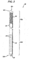
- FIG. 2 illustrates an exemplary embodiment of a pressure sensing catheter 30 according to the invention.
- the catheter 30 is similar to catheter 10 in that it includes an elongate body 32 having proximal and distal ends 32a, 32b with an inner lumen 32c extending therebetween, and several fluid entry ports 34 formed in a distal portion 32d of the elongate body 32 and in fluid communication with the inner lumen 32c to allow fluid to flow therethrough.
- the catheter 30 also includes a pressure sensor 36 that is disposed within the distal end 32b of the elongate body 32 and a connector 40 that extends from the pressure sensor 36 to mate to an antenna 38.
- the pressure sensor 36 and connector 40 can be coupled to the elongate body 32 as previously described, or they can have a variety of other configurations as will be described in more detail with respect to FIGS. 3-7B .
- the embodiment shown in FIG. 2 differs from the embodiment shown in FIG. 1 in that the antenna 38 is not separate from and external to the elongate body 32, but rather it is coupled to a proximal portion 32p of the elongate body 32.
- the antenna 38 is formed into a cylindrical-shaped coil and is embedded within the elongate body 32. This can be achieved by molding the elongate body 32 around the antenna 38.
- the connector 40 is coupled to the antenna 38 and is also molded within the elongate body 32.
- the antenna 38 can be wrapped around the elongate body 32 or it can be disposed within the inner lumen 32c of the elongate body 32.
- An adhesive can optionally be used to fix the antenna 18 to the elongate body 12.
- the antenna 38 which is disposed in the proximal portion 32p of the elongate body 32, can be positioned outside of the ventricle and adjacent to the patient's scalp to allow a reading to be obtained from the pressure sensor 32 via the antenna 38. Accordingly, in an exemplary embodiment, the antenna 38 should be positioned at a location on the elongate body 32 that allows for such positioning of the antenna 38 during use.
- the catheter 30 can also include a coating applied to the pressure sensor 36, antenna 38, connector 40, and/or the elongate body 32.
- the coating is only applied to the pressure sensor 36, or at least to the portion of the pressure sensor 36 that is exposed to the external environment, as the catheter forms a seal around the connector 40 and antenna 38 that are embedded therein.
- the pressure sensor 36 can be disposed within a recess formed in the elongate body 32 and the coating can be applied over the recess to seal the pressure sensor 36 therein.
- FIGS. 3-7B illustrate a variety of other configurations for the pressure sensor and connector with respect to the elongate body.
- the antenna coupling to the pressure sensor and connector can be coupled to the catheter, or it can be separate from and external to the catheter.
- the pressure sensor and connector can have a variety of configurations, in certain exemplary embodiments the pressure sensor and/or connector can be positioned within the inner lumen of the elongate body, positioned within a second inner lumen in the elongate body, embedded in the elongate body, disposed on an external surface of the elongate body, and/or positioned external to the elongate body.
- a coating can be applied to the pressure sensor and/or connector, however the particular technique used to hermetically seal the pressure sensor and connector in each embodiment can depend on the configuration of the pressure sensor and connector, as well as the antenna (shown in FIGS. 1 and 2 ), and whether the antenna is internal or external to the elongate body. Exemplary methods for manufacturing each embodiment and for hermetically sealing the pressure sensor and connector are also disclosed.
- the pressure sensing catheter can have a variety of configurations, and that the method for manufacturing the pressure sensing catheter can vary depending on the configuration.
- FIG. 3 illustrates a distal portion 50 of an elongate body 52 of a pressure sensing catheter.
- the pressure sensor 56 and the connector 58 are disposed on an external surface of the elongate body 52.
- An adhesive or any other mating technique can be used to attach the pressure sensor 56 and connector 58 to the body 52.
- a coating can be applied to some or all of the device, as previously described.
- the sensor assembly can be pre-coated prior to coupling the sensor assembly to the elongate body 52.
- a coating can be applied to the elongate body 52 after the sensor assembly is coupled thereto.
- the fluid-entry ports should, of course, be free from any coating to allowing fluid to flow therethrough.
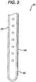
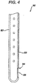
- FIG. 4 illustrates an embodiment according to the invention of a distal portion 60 of an elongate body 62 of a pressure sensing catheter.
- the pressure sensor 66 is disposed within a recess 64 formed in the elongate body 62, and the connector 68 is embedded within the elongate body 62.
- the connector 68 can be embedded in the elongate body 62 during molding, and the recess 64 can either be molded into the elongate body 62 or it can be cut out of the elongate body 62 after the elongate body 62 is formed.
- the sensor 66 can thereafter be positioned within the recess 64.
- an adhesive or any other mating technique can be used to retain the pressure sensor 66 within the recess 64.
- a coating can be applied to the pressure sensor 66 prior to and/or after disposing the pressure sensor 66 in the recess 64.
- the coating can optionally be applied to the elongate body 62 to seal the pressure sensor 66 within the recess 64.
- FIG. 5 illustrates another embodiment according to the invention, of a distal portion 70 of an elongate body 72 of a pressure sensing catheter.
- the pressure sensor 76 and the connector 78 are disposed within the inner lumen 70c of the elongate body 72.
- a cut-out or window 74 is formed in the elongate body 72 to expose a portion of the pressure sensor 76 that is adapted to measure the pressure surrounding the catheter.
- a coating is preferably disposed over the sensor assembly before it is disposed within the elongate body 72, and an adhesive of other mating technique can be used to attach the sensor assembly to the elongate body 72.
- a coating can optionally be applied to the window 74.
- FIG. 6 illustrates another embodiment according to the invention of a distal portion 80 of an elongate body 82 of a pressure sensing catheter.
- the elongate body 82 includes first and second inner lumens 82a, 82b, and the pressure sensor 86 and the connector 88 are disposed within the second inner lumen 82b.
- a cut-out or window 84 is formed in the elongate body 82 and is in commu- nication with the second inner lumen 82b to expose a portion of the pressure sensor 86 that is adapted to meas- ure the pressure surrounding the catheter.
- a coating can either be disposed over the sensor assembly before it is disposed within the second inner lumen 82b in the elongate body 82, or a coating can be applied to the window 84 to seal the pressure sensor 86 and connector 88 within the elongate body 82.
- FIGS. 7A and 7B illustrate another embodiment according to the invention of a distal portion 90 of an elongate body 92 of a pressure sensing catheter.
- the pressure sensor 96 is disposed within a bullet-shaped tip 95 that is attached to the elongate body 92.
- the bullet-shaped tip 95 and elongate body 92 can be manufactured as separate components and then coupled to one another to couple the pressure sensor 96 to the connector 98.
- the pressure sensor 96 is disposed within a recess 94 formed in the distal-most end of the bullet-shaped tip 95, however a portion of the pressure sensor 96 preferably extends from the recess 94 to allow the external pressure to be measured.
- An adhesive can be used to retain the pressure sensor 96 within the tip 95, and a coating can be applied to the pressure sensor 96 and/or the tip 95.
- the elongate body 92 can be formed with the connector 98 embedded therein.
- An adhesive or other mating technique can then be used to attach the bullet- shaped tip 95 to the open distal end of the elongate body 92.
- the connector 98 disposed within the elongate body 92 can then be coupled to the pressure sensor 96 in the tip 95.
- Various techniques can be used to achieve a connection. For example, a portion of the connector 98 can be embedded or disposed within the tip 95 and connected to the pressure sensor 96 when the pressure sensor 96 is inserted into the recess 94.
- the two portions of the connector 98 can then be mated to one another when the tip 95 is attached to the elongate body 92.
- the recess can extend completely through the distal tip 92 to allow a portion of the connector 98 extending from the elongate body 92 to be connected to the pressure sensor 96.
- various techniques can be used to hermetically seal the pressure sensor 96, connector 98, and antenna (shown in FIGS. 1 and 2 ).
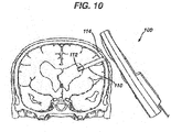
- FIGS. 10 and 11 shown exemplary methods for using a pressure sensing catheter.
- a pressure sensing catheter 110 not falling within the scope of the claims is shown having a pressure sensor 112 (labeled “chip”) disposed within the distal end thereof, and an external antenna 114 (labeled “coil”) positioned a distance apart from a proximal end thereof.
- the catheter 110 is positioned in the patient's ventricle, and the external antenna 114 is positioned just beneath just beneath the patient's scalp.
- the pressure sensor 112 which is exposed to the fluid surrounding the catheter 110, can measure the ventricular pressure surrounding the catheter 110.
- An external device 100 as shown, can then be positioned adjacent to the antenna 114 to telemetrically communicate with the antenna 114, and thereby obtain a reading of the measured pressure.
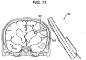
- FIG. 11 similarly illustrates a pressure sensing catheter 120 having a pressure sensor 112 disposed within a patient's ventricle for measuring the intra-ventricular pressure.
- the antenna 124 is internal to the catheter 120, however it is still positioned just beneath the patient's scalp. The device 120 therefore functions in the same manner described above with respect to FIG. 10 .
- Multiple pressure sensor assemblies can also be used, and they can be disposed at various locations relative to one another.
- the use of multiple pressure sensor assemblies can be particularly advantageous as it can allow a differential pressure of the system to be obtained.
- the differential pressure of the system should be equal to the operating pressure of the system, thus indicating whether the system is performing properly.
Description
- The present invention relates to ventricular catheters, and in particular to a catheter device having a pressure sensor disposed therein. A pressure sensing ventricular catheter is disclosed for example in
EP-A-1 512 427 . - Hydrocephalus is a neurological condition that is caused by the abnormal accumulation of cerebrospinal fluid (CSF) within the ventricles, or cavities, of the brain. CSF is a clear, colorless fluid that is primarily produced by the choroid plexus and surrounds the brain and spinal cord. CSF constantly circulates through the ventricular system of the brain and is ultimately absorbed into the bloodstream. CSF aids in the protection of the brain and spinal cord. Because CSF keeps the brain and spinal cord buoyant, it acts as a protective cushion or "shock absorber" to prevent injuries to the central nervous system.
- Hydrocephalus, which affects children and adults, arises when the normal drainage of CSF in the brain is blocked in some way. Such blockage can be caused by a number of factors, including, for example, genetic predisposition, intra-ventricular or intra-cranial hemorrhage, infections such as meningitis, head trauma, or the like. Blockage of the flow of CSF consequently creates an imbalance between the amount of CSF produced by the choroid plexus and the rate at which CSF is absorbed into the bloodstream, thereby increasing pressure on the brain, which causes the ventricles to enlarge.
- Hydrocephalus is most often treated by surgically inserting a shunt system that diverts the flow of CSF from the ventricle to another area of the body where the CSF can be absorbed as part of the circulatory system. Shunt systems come in a variety of models, and typically share similar functional components. These components include a ventricular catheter which is introduced through a burr hole in the skull and implanted in the patient's ventricle, a drainage catheter that carries the CSF to its ultimate drainage site, and optionally a flow-control mechanism, e.g., shunt valve, that regulates the one-way flow of CSF from the ventricle to the drainage site to maintain normal pressure within the ventricles. The ventricular catheter typically contains multiple holes or pores positioned along the length of the ventricular catheter to allow the CSF to enter into the shunt system. To facilitate catheter insertion, a removable rigid stylet, situated within the lumen of the ventricular catheter, is used to direct the catheter toward the desired targeted location. Alternatively, or in addition, blunt tip brain cannulas and peel-away sheaths have been used to aid placement of the catheters.
- One common problem encountered with the use of ventricular catheters is the difficulty in measuring the pressure within the patient's ventricle. One current technique involves placing a pressure sensor in line with the catheter and external to the ventricles such that the sensor communicates with the cerebrospinal fluid flowing through the catheter. As the pressure drop across the catheter is negligible, the sensor can measure pressure that resembles the intra-ventricular pressure. While this technique is advantageous in that it allows the use of a relatively large sensor, catheter blockage can impede the pressure sensed by the sensor, thus preventing an accurate measurement of intra-ventricular pressure from being obtained.
- Accordingly, there remains a need for a catheter having a pressure sensor that is effective to accurately measure a patient's ventricular pressure.
-
EP-A-1 389 477 discloses a device for tip pressure monitoring for cryoablation catheters having some of the features of the present invention. - The present invention generally provides pressure sensing ventricular catheters as defined in claims 1 to 5. The devices are particularly advantageous in that they provide a sensor assembly that is hermetically sealed, thereby allowing the device to be permanently implanted, and that can be effective to directly measure the intra- ventricular pressure, thus avoiding potentially inaccurate readings due to blockages occurring in the catheter.
- The pressure sensor is coupled to the catheter using a variety of techniques. The pressure sensor can be disposed within a recess formed in an external surface of the elongate body. The pressure sensor can be embedded within the elongate body, and the elongate body can include an opening formed therein for exposing at least a portion of the pressure sensor to an external environment. The pressure sensor can be embedded within a distal tip of the elongate body, and a portion of the pressure sensor can protrude beyond the distal tip of the elongate body to measure a pressure of an external environment. The pressure sensor can be disposed within the inner lumen of the elongate body, and the elongate body can include an opening formed therein for exposing at least a portion of the pressure sensor to an external environment. The elongate body can include a second inner lumen extending therethrough, and the pressure sensor can be disposed within the second inner lumen of the elongate body and the elongate body includes an opening formed therein and extending into the second inner lumen for exposing at least a portion of the pressure sensor to an external environment.
- In other aspects, at least a portion of the pressure sensing catheter can include a biocompatible fluid-impermeable coating for hermetically sealing the pressure sensor, the antenna, and/or a connector extending between the pressure sensor and the antenna. In one exemplary embodiment, the pressure sensor, antenna, and the connector extending therebetween can be coated to form a hermetically sealed sensor assembly. In other embodiments, only a portion of the pressure sensor, the antenna, and/or the connector can be coated. For example, a portion of the pressure sensor that is configured to be exposed to fluid during use can be coated. In yet another embodiment, the catheter can be coated such that any portion of the pressure sensor, the antenna, and the connector exposed to an external environment are coated. Where the catheter is coated, the fluid-entry ports formed in the catheter are preferably clear from any coating that would otherwise prevent fluid flow therethrough. The particular coating used can also vary, but in one exemplary embodiment the coating is a solvent-based silicone.
- Methods for manufacturing intra-ventricular pressure sensor devices are also disclosed. In one exemplary embodiment, a catheter is formed having a distal end with a pressure sensor. At least a portion of the pressure sensor can be exposed to an ex- ternal environment such that the pressure sensor is adapted to measure a pressure surrounding the catheter. The catheter can also include an inner lumen extending therethrough, at least one fluid-entry port formed therein and in fluid communication with the inner lumen, an antenna coupled to the pressure sensor and adapted to communicate a measured pressure to an external device, and a connector extending between the pressure sensor and the antenna.
- Where the antenna is embedded within the catheter, the catheter can be extruded with the antenna and at least a portion of the connector disposed therein. In other embodiments, the connector can be disposed within a slot formed in a sidewall of the catheter and extending along at least a portion of the length thereof. The method of manufacturing the catheter can also vary depending on the configuration of the pressure sensor. In one exemplary embodiment, the catheter can include a bullet-shaped tip that is coupled to a distal end thereof, and at least a portion of the pressure sensor can be disposed within the bullet- shaped tip. In another exemplary embodiment, the catheter can be manufactured by coupling the antenna, connector, and pressure sensor to form a sensor assembly, coating the sensor assembly such that it is fluid-impermeable, and coupling the sensor assembly to the catheter. The sensor assembly can be coupled to the catheter by, for example, attaching the sensor assembly to an external surface of the catheter, or positioning some of all of the sensor assembly in cutouts, slots, or recesses formed in the catheter.
- The invention will be more fully understood from the following detailed description taken in conjunction with the accompanying drawings, in which:
-
FIG. 1 is a perspective view of one exemplary embodiment of a pressure sensing catheter having an external antenna not falling within the scope of the claims; -
FIG. 2 is a cross-sectional view of an exemplary embodiment of a pressure sensing catheter having an internal antenna; -
FIG. 3 is a cross-sectional view of one embodiment not according to the present invention of a distal portion of a pressure sensing catheter having a pressure sensor disposed on an external surface thereof; -
FIG. 4 is a cross-sectional view of another embodiment of a distal portion of a pressure sensing catheter having a pressure sensor disposed within a recess formed therein; -
FIG. 5 is a cross-sectional view of yet another embodiment of a distal portion of a pressure sensing catheter having a pressure sensor disposed within an inner lumen formed therein, and having a window formed therein for exposing a portion of the pressure sensor to an external environment; -
FIG. 6 is a cross-sectional view of another embodiment of a distal portion of a pressure sensing catheter having a pressure sensor disposed within a second lumen formed in the catheter; -
FIG. 7A is a cross-sectional view of yet another embodiment of a distal portion of a pressure sensing catheter having a pressure sensor disposed within a distal tip of the catheter; -
FIG. 7B is a cross-sectional view of the distal tip of the catheter show inFIG. 7A taken across line B-B; -
FIG. 8 is a top view of an exemplary embodiment of a pressure sensor; -
FIG. 9A is a perspective view of an exemplary embodiment of an external radiofrequency telemetry system; -
FIG. 9B is a perspective view of the external radiofrequency telemetry system ofFIG. 9A in a disassembled configuration; -
FIG. 10 is a cross-sectional view of a human brain showing one embodiment of a ventricular catheter not falling within the scope of the claims having a distal portion implanted in the ventricle and having an external antenna positioned under the patient's scalp; -
FIG. 11 is a cross-sectional view of a human brain showing one embodiment of a ventricular catheter having a distal portion implanted in the ventricle and having an internal antenna positioned under the patient's scalp; - The present invention generally provides devices for measuring an intra-ventricular pressure. The devices are particularly advantageous in that they provide a hermetically sealed pressure sensing assembly that allows the device to be effective for long term or permanent implantation. In certain exemplary embodiment, the devices are also particularly advantageous in that they can be effective to obtain a direct measurement of the intra-ventricular pressure, thereby avoiding potentially inaccurate readings due to a blockage occurring in the ventricular catheter. A person skilled in the art will appreciate that, while the device is described in connection with a ventricular catheter for measuring the intra-ventricular pressure, the device can be used for a variety of medical procedures to measure the pressure in a variety of cavities.
- In one exemplary embodiment, the present invention provides a pressure sensing catheter having a pressure sensor and an antenna that is coupled to the pressure sensor, e.g., by a connector. The pressure sensor can be adapted to measure a pressure surrounding the catheter, and the antenna can be adapted to telemetrically communicate the measured pressure to an external device. In an exemplary embodiment, the antenna, pressure sensor, and/or connector are hermetically sealed by the catheter and/or a coating to prevent the antenna, pressure sensor, and connector from coming into contact with fluid, thereby allowing the catheter to be permanently implanted or otherwise used for long term use. The catheter and/or coating are also particularly effective to prevent damage to the components due to the corrosive in-vivo environment. The catheter and/or coating should not, however, interfere with the ability of the pressure sensor to sense the pressure of fluid in contact therewith. Exemplary catheter configurations are discussed in the various embodiments described and illustrated herein, however a person having ordinary skill in the art will appreciate that the pressure sensing catheter can have a variety of other configurations. Moreover, the pressure sensor, antenna, and connector can be incorporated into virtually any catheter or other device.
-
FIG. 1 illustrates one exemplary embodiment of apressure sensing catheter 10 not falling within the scope of the claims. As shown, thecatheter 10 has a generallyelongate body 12 with proximal anddistal ends inner lumen 12c extending therethrough for accommodating fluid flow. Theinner lumen 12c preferably terminates just proximal to thedistal end 12b such that thedistal end 12b is closed. Theproximal end 12a can be open and it can be adapted to couple to another medical device, such as a valve for controlling fluid flow from thecatheter 10. Thecatheter 10 can also include at least one fluid-entry port 14 formed in a sidewall thereof and extending into theinner lumen 12c. The location, quantity, and size of the fluid-entry ports 14 can vary, but they should be adapted to allow fluid to flow therethrough and into theinner lumen 12c. - The
elongate body 12 that forms thecatheter 10 can have virtually any configuration, shape, and size. Preferably, theelongate body 12 has a length I that is sufficient to allow at least thedistal portion 12d to be implanted in a patient's ventricles, while the proximal portion 12p can extend therefrom to connect to another medical device, such as a valve. Theelongate body 12 can also be formed from a variety of materials. In an exemplary embodiment, however, thebody 12 is formed from a flexible, biocompatible material. Suitable materials include, for example, polymers such as silicones, polyethylene, and polyurethanes, all of which are known in the art. Thebody 12 can also optionally be formed from a radio-opaque material. A person skilled in the art will appreciate that the materials are not limited to those listed herein and that a variety of other biocompatible materials having the appropriate physical properties to enable the desired performance characteristics can be used. - As is further shown in
FIG. 1 , thecatheter 10 also includes apressure sensor 16 that is adapted to measure a pressure of an external environment, e.g., the pressure in the ventricle, surrounding thecatheter 10, and anantenna 18 that is adapted to communicate the measured pressure to an external device. Thepressure sensor 16 and theantenna 18 can be coupled to one another using a variety of techniques, but in the embodiment shown inFIG. 1 aconnector 20 extends between thepressure sensor 16 and theantenna 18. - Exemplary embodiments of a
pressure sensor 16,connector 20, andantenna 18 are described in more detail inU.S. Patent No. 5,321,989 ,U.S. Patent No. 5,431,057 , andEP Patent No. 1 312 302 . In general, thepressure sensor 16 can be formed on a microchip, as shown inFIG. 8 . The size of thepressure sensor 16 can vary, but in one exemplary embodiment thepressure sensor 16 has a length of about 7 mm and a width of about 1 mm. Theconnector 20 that mates thepressure sensor 16 to theantenna 18 can also vary, but in an exemplary embodiment theconnector 20 is a gold wire or other conductive element. Theantenna 18 can also have a variety of configurations, but in an exemplary embodiment theantenna 18 preferably has a coil-shaped configuration. In particular, as shown inFIG. 1 , theantenna 18 is formed into a substantially circular coil. Another embodiment of anantenna 38 is shown inFIG 2 , and in that embodiment theantenna 38 is wrapped around theelongate body 12 to form a substantially cylindrical coil. The coil configuration will allow theantenna frequency telemetry device 100 shown inFIG. 9A and 9B . The telemetry device is described in more detail inEP Patent No. 1 312 302 . - Continuing to refer to
FIG. 1 , the particular configuration of thepressure sensor 16,connector 20, andantenna 18 with respect to thecatheter 10 can vary. In the embodiment shown inFIG. 1 , thepressure sensor 16 is disposed within a cut-out or recess 22 formed in theelongate body 12 adjacent to thedistal end 12b. Therecess 22 can extend partially through theelongate body 12, or it can extend fully through theelongate body 12 such that it is in communication with theinner lumen 12c. The position of therecess 22 can vary, but in an exemplary embodiment therecess 22 is formed distal of the distal-mostfluid entry port 14. Such a configuration allows thepressure sensor 16 to be fully positioned within the ventricle to obtain an accurate reading. - As further shown in
FIG. 1 , theconnector 20 is disposed within anelongate slot 24 formed in theelongate body 12 and extending proximally from therecess 22. A proximal portion of theconnector 20 extends from theelongate slot 24 to mate to theantenna 18. As shown, theantenna 18 is not attached to theelongate body 12, but rather it is separate from theelongate body 12 and it is coupled to a proximal end of theconnector 20. Such a configuration allows theantenna 18 to be positioned a distance apart from theelongate body 12. For example, when thepressure sensing catheter 10 is implanted in a patient's ventricle, theantenna 18 can be positioned just underneath the patient's scalp. This will allow an external device to be placed adjacent to theantenna 18 to telemetrically communicate with theantenna 18 and receive a pressure reading obtained by thepressure sensor 16, as will be discussed in more detail below. Theelongate slot 24 also allows theconnector 20 andantenna 18 to optionally be separated from theelongate body 12 if necessary. For example, theantenna 18 may need to be positioned a particular distance away from theelongate body 12, or theelongate body 12 may need to be trimmed, in which case an additional portion of theconnector 20 can be removed from theslot 24. - As indicated above, the
pressure sensor 16,connector 20,antenna 18, and/or theelongate body 12 can also include a coating that is adapted to hermetically seal all or at least a portion of thepressure sensor 16,connector 20, andantenna 18. The coating can be applied to only a portion of thepressure sensor 16,connector 20, andantenna 18 that will be exposed to fluid within the patient's ventricle, or it can be applied to each of thepressure sensor 16,connector 20,antenna 18, and optionally theelongate body 12. In the embodiment shown inFIG. 1 , thepressure sensor 16,connector 20, andantenna 18, hereinafter collectively referred to as the sensor assembly, are preferably pre-coated prior to coupling the sensor assembly to theelongate body 12. Once coated thepressure sensor 16 can be positioned within therecess 22 and theconnector 20 can be positioned within theslot 24. An adhesive or other mating technique can optionally be used to affix thepressure sensor 16 within therecess 22, and optionally to affix theconnector 20 within theslot 24. Any adhesive or other mating technique can be used to attach theconnector 20 to theelongate body 12, however, if desirable it should be configured to allow theconnector 20 to be torn away from thebody 12 if necessary. - Alternatively, or in addition to pre-coating, the
catheter 10 can be coated after the sensor assembly is coupled to theelongate body 12 to form a protective sheath over the sensor assembly. The fluid-entry ports 14 should, however, either be protected from any coating applied thereto, formed after the coating is applied, or be cleared of any coating applied thereto to allow fluid to flow therethrough and into theinner lumen 12c. In other embodiments, only certain components of the sensor assembly can be coated. A person skilled in the art will appreciate that a variety of other techniques can be used to hermitically seal thepressure sensor 16,connector 20, andantenna 18. - The material used to form the coating can vary, and a variety of techniques can be used to apply the coating. By way of non-limiting example, suitable materials include polyurethane, silicone, solvent-based polymer solutions, and any other polymer that will adhere to the components to which it is applied to, and suitable techniques for applying the coating include spray-coating or dip-coating.
-
FIG. 2 illustrates an exemplary embodiment of apressure sensing catheter 30 according to the invention. Thecatheter 30 is similar tocatheter 10 in that it includes anelongate body 32 having proximal anddistal ends inner lumen 32c extending therebetween, and severalfluid entry ports 34 formed in adistal portion 32d of theelongate body 32 and in fluid communication with theinner lumen 32c to allow fluid to flow therethrough. Thecatheter 30 also includes apressure sensor 36 that is disposed within thedistal end 32b of theelongate body 32 and aconnector 40 that extends from thepressure sensor 36 to mate to anantenna 38. Thepressure sensor 36 andconnector 40 can be coupled to theelongate body 32 as previously described, or they can have a variety of other configurations as will be described in more detail with respect toFIGS. 3-7B . - The embodiment shown in
FIG. 2 differs from the embodiment shown inFIG. 1 in that theantenna 38 is not separate from and external to theelongate body 32, but rather it is coupled to aproximal portion 32p of theelongate body 32. In particular, theantenna 38 is formed into a cylindrical-shaped coil and is embedded within theelongate body 32. This can be achieved by molding theelongate body 32 around theantenna 38. Preferably, theconnector 40 is coupled to theantenna 38 and is also molded within theelongate body 32. In other embodiments, theantenna 38 can be wrapped around theelongate body 32 or it can be disposed within theinner lumen 32c of theelongate body 32. An adhesive can optionally be used to fix theantenna 18 to theelongate body 12. In use, as will be discussed in more detail with respect toFIG. 11 , theantenna 38, which is disposed in theproximal portion 32p of theelongate body 32, can be positioned outside of the ventricle and adjacent to the patient's scalp to allow a reading to be obtained from thepressure sensor 32 via theantenna 38. Accordingly, in an exemplary embodiment, theantenna 38 should be positioned at a location on theelongate body 32 that allows for such positioning of theantenna 38 during use. - As previously discussed with respect to
FIG. 1 , thecatheter 30 can also include a coating applied to thepressure sensor 36,antenna 38,connector 40, and/or theelongate body 32. In an exemplary embodiment, the coating is only applied to thepressure sensor 36, or at least to the portion of thepressure sensor 36 that is exposed to the external environment, as the catheter forms a seal around theconnector 40 andantenna 38 that are embedded therein. For example, thepressure sensor 36 can be disposed within a recess formed in theelongate body 32 and the coating can be applied over the recess to seal thepressure sensor 36 therein. -
FIGS. 3-7B illustrate a variety of other configurations for the pressure sensor and connector with respect to the elongate body. While not shown, the antenna coupling to the pressure sensor and connector can be coupled to the catheter, or it can be separate from and external to the catheter. While the pressure sensor and connector can have a variety of configurations, in certain exemplary embodiments the pressure sensor and/or connector can be positioned within the inner lumen of the elongate body, positioned within a second inner lumen in the elongate body, embedded in the elongate body, disposed on an external surface of the elongate body, and/or positioned external to the elongate body. A coating can be applied to the pressure sensor and/or connector, however the particular technique used to hermetically seal the pressure sensor and connector in each embodiment can depend on the configuration of the pressure sensor and connector, as well as the antenna (shown inFIGS. 1 and2 ), and whether the antenna is internal or external to the elongate body. Exemplary methods for manufacturing each embodiment and for hermetically sealing the pressure sensor and connector are also disclosed. A person skilled in the art will appreciate that the pressure sensing catheter can have a variety of configurations, and that the method for manufacturing the pressure sensing catheter can vary depending on the configuration. -
FIG. 3 illustrates adistal portion 50 of an elongate body 52 of a pressure sensing catheter. In this embodiment, which is not according to the present invention, thepressure sensor 56 and theconnector 58 are disposed on an external surface of the elongate body 52. An adhesive or any other mating technique can be used to attach thepressure sensor 56 andconnector 58 to the body 52. In order to protect thesensor 56 andconnector 58 from fluid damage, a coating can be applied to some or all of the device, as previously described. For example, the sensor assembly can be pre-coated prior to coupling the sensor assembly to the elongate body 52. Alternatively, or in addition, a coating can be applied to the elongate body 52 after the sensor assembly is coupled thereto. The fluid-entry ports should, of course, be free from any coating to allowing fluid to flow therethrough. -
FIG. 4 illustrates an embodiment according to the invention of adistal portion 60 of anelongate body 62 of a pressure sensing catheter. In this embodiment, which is similar to the embodiment shown inFIG. 1 , thepressure sensor 66 is disposed within arecess 64 formed in theelongate body 62, and theconnector 68 is embedded within theelongate body 62. Theconnector 68 can be embedded in theelongate body 62 during molding, and therecess 64 can either be molded into theelongate body 62 or it can be cut out of theelongate body 62 after theelongate body 62 is formed. Thesensor 66 can thereafter be positioned within therecess 64. As previously discussed, an adhesive or any other mating technique can be used to retain thepressure sensor 66 within therecess 64. A coating can be applied to thepressure sensor 66 prior to and/or after disposing thepressure sensor 66 in therecess 64. The coating can optionally be applied to theelongate body 62 to seal thepressure sensor 66 within therecess 64. -
FIG. 5 illustrates another embodiment according to the invention, of adistal portion 70 of anelongate body 72 of a pressure sensing catheter. In this embodiment, thepressure sensor 76 and the connector 78 are disposed within theinner lumen 70c of theelongate body 72. A cut-out orwindow 74 is formed in theelongate body 72 to expose a portion of thepressure sensor 76 that is adapted to measure the pressure surrounding the catheter. A coating is preferably disposed over the sensor assembly before it is disposed within theelongate body 72, and an adhesive of other mating technique can be used to attach the sensor assembly to theelongate body 72. A coating can optionally be applied to thewindow 74. -
FIG. 6 illustrates another embodiment according to the invention of adistal portion 80 of anelongate body 82 of a pressure sensing catheter. In this embodiment, theelongate body 82 includes first and secondinner lumens pressure sensor 86 and theconnector 88 are disposed within the secondinner lumen 82b. A cut-out orwindow 84 is formed in theelongate body 82 and is in commu- nication with the secondinner lumen 82b to expose a portion of thepressure sensor 86 that is adapted to meas- ure the pressure surrounding the catheter. A coating can either be disposed over the sensor assembly before it is disposed within the secondinner lumen 82b in theelongate body 82, or a coating can be applied to thewindow 84 to seal thepressure sensor 86 andconnector 88 within theelongate body 82. -
FIGS. 7A and 7B illustrate another embodiment according to the invention of adistal portion 90 of anelongate body 92 of a pressure sensing catheter. In this embodiment, thepressure sensor 96 is disposed within a bullet-shapedtip 95 that is attached to theelongate body 92. The bullet-shapedtip 95 andelongate body 92 can be manufactured as separate components and then coupled to one another to couple thepressure sensor 96 to theconnector 98. As shown inFIGS. 7A and 7B , thepressure sensor 96 is disposed within arecess 94 formed in the distal-most end of the bullet-shapedtip 95, however a portion of thepressure sensor 96 preferably extends from therecess 94 to allow the external pressure to be measured. An adhesive can be used to retain thepressure sensor 96 within thetip 95, and a coating can be applied to thepressure sensor 96 and/or thetip 95. As is further shown inFIG. 7A , theelongate body 92 can be formed with theconnector 98 embedded therein. An adhesive or other mating technique can then be used to attach the bullet- shapedtip 95 to the open distal end of theelongate body 92. Theconnector 98 disposed within theelongate body 92 can then be coupled to thepressure sensor 96 in thetip 95. Various techniques can be used to achieve a connection. For example, a portion of theconnector 98 can be embedded or disposed within thetip 95 and connected to thepressure sensor 96 when thepressure sensor 96 is inserted into therecess 94. The two portions of theconnector 98 can then be mated to one another when thetip 95 is attached to theelongate body 92. Alternatively, the recess can extend completely through thedistal tip 92 to allow a portion of theconnector 98 extending from theelongate body 92 to be connected to thepressure sensor 96. As previously discussed, various techniques can be used to hermetically seal thepressure sensor 96,connector 98, and antenna (shown inFIGS. 1 and2 ). -
FIGS. 10 and11 shown exemplary methods for using a pressure sensing catheter. Referring first toFIG. 10 , apressure sensing catheter 110 not falling within the scope of the claims is shown having a pressure sensor 112 (labeled "chip") disposed within the distal end thereof, and an external antenna 114 (labeled "coil") positioned a distance apart from a proximal end thereof. As shown, thecatheter 110 is positioned in the patient's ventricle, and theexternal antenna 114 is positioned just beneath just beneath the patient's scalp. Thepressure sensor 112, which is exposed to the fluid surrounding thecatheter 110, can measure the ventricular pressure surrounding thecatheter 110. Anexternal device 100, as shown, can then be positioned adjacent to theantenna 114 to telemetrically communicate with theantenna 114, and thereby obtain a reading of the measured pressure. -
FIG. 11 similarly illustrates apressure sensing catheter 120 having apressure sensor 112 disposed within a patient's ventricle for measuring the intra-ventricular pressure. In this embodiment, theantenna 124 is internal to thecatheter 120, however it is still positioned just beneath the patient's scalp. Thedevice 120 therefore functions in the same manner described above with respect toFIG. 10 . - Multiple pressure sensor assemblies can also be used, and they can be disposed
at various locations relative to one another. The use of multiple pressure sensor assemblies can be particularly advantageous as it can allow a differential pressure of the system to be obtained. The differential pressure of the system should be equal to the operating pressure of the system, thus indicating whether the system is performing properly.
Claims (7)
- A pressure sensing ventricular catheter (10) for measuring intra-ventricular pressure in a brain comprising:an elongate body (12) having an inner lumen (12c) extending at least partially therethrough, a distal portion having a distal end having a pressure sensor (16), at least a portion of the pressure sensor (16) being exposed to an external environment surrounding the catheter (10) such that the pressure sensor (16) is effective to measure the pressure of the external environment, wherein the pressure sensor (16) is disposed within a recess formed in an external surface of the elongate body (12);at least one fluid-entry port (14, 34) formed in the elongate body proximal to the pressure sensor and in fluid communication with the inner lumen (12c); andan antenna (18) coupled to the pressure sensor (16) and adapted to communicate a measured pressure from the pressure sensor (16) to an external device;wherein the antenna (18) comprises a coil coupled to the pressure sensor (16) by a connector, and the coil is either:(a) disposed around the elongate body (12); or(b) embedded within the elongate body (12).
- A pressure sensing ventricular catheter (10) for measuring intra-ventricular pressure in a brain comprising:an elongate body (12) having an inner lumen (12c) extending at least partially therethrough, a distal portion having a distal end having a pressure sensor (16), at least a portion of the pressure sensor (16) being exposed to an external environment surrounding the catheter (10) such that the pressure sensor (16) is effective to measure the pressure of the external environment, wherein the pressure sensor (16) is embedded within the elongate body (12), and wherein the elongate body (12) includes an opening formed therein for exposing at least a portion of the pressure sensor (16) to an external environment;at least one fluid-entry port (14, 34) formed in the elongate body proximal to the pressure sensor and in fluid communication with the inner lumen (12c); andan antenna (18) coupled to the pressure sensor (16) and adapted to communicate a measured pressure from the pressure sensor (16) to an external device;wherein the antenna (18) comprises a coil coupled to the pressure sensor (16) by a connector, and the coil is either:(a) disposed around the elongate body (12); or(b) embedded within the elongate body (12).
- A pressure sensing ventricular catheter (10) for measuring intra-ventricular pressure in a brain comprising:an elongate body (12) having an inner lumen (12c) extending at least partially therethrough, a distal portion having a distal end having a pressure sensor (16), at least a portion of the pressure sensor (16) being exposed to an external environment surrounding the catheter (10) such that the pressure sensor (16) is effective to measure the pressure of the external environment, wherein the pressure sensor (16) is embedded within a distal tip of the elongate body (12), and wherein the portion of the pressure sensor (16) protrudes beyond the distal tip of the elongate body (12) to measure a pressure of an external environment;at least one fluid-entry port (14, 34) formed in the elongate body proximal to the pressure sensor and in fluid communication with the inner lumen (12c); andan antenna (18) coupled to the pressure sensor (16) and adapted to communicate a measured pressure from the pressure sensor (16) to an external device;wherein the antenna (18) comprises a coil coupled to the pressure sensor (16) by a connector, and the coil is either:(a) disposed around the elongate body (12); or(b) embedded within the elongate body (12).
- A pressure sensing ventricular catheter (10) for measuring intra-ventricular pressure in a brain comprising:an elongate body (12) having an inner lumen (12c) extending at least partially therethrough, a distal portion having a distal end having a pressure sensor (16), at least a portion of the pressure sensor (16) being exposed to an external environment surrounding the catheter (10) such that the pressure sensor (16) is effective to measure the pressure of the external environment, wherein the pressure sensor (16) is disposed within the inner lumen (12c) of the elongate body (12), and wherein the elongate body (12) includes an opening formed therein for exposing at least a portion of the pressure sensor (16) to an external environment;at least one fluid-entry port (14, 34) formed in the elongate body proximal to the pressure sensor and in fluid communication with the inner lumen (12c); andan antenna (18) coupled to the pressure sensor (16) and adapted to communicate a measured pressure from the pressure sensor (16) to an external device;wherein the antenna (18) comprises a coil coupled to the pressure sensor (16) by a connector, and the coil is either:(a) disposed around the elongate body (12); or(b) embedded within the elongate body (12).
- A pressure sensing ventricular catheter (10) for measuring intra-ventricular pressure in a brain comprising:an elongate body (12) having an inner lumen (12c) extending at least partially therethrough, a distal portion having a distal end having a pressure sensor (16), at least a portion of the pressure sensor (16) being exposed to an external environment surrounding the catheter (10) such that the pressure sensor (16) is effective to measure the pressure of the external environment, wherein the elongate body (12) includes a second inner lumen extending therethrough, and wherein the pressure sensor (16) is disposed within the second inner lumen of the elongate body (12), the elongate body (12) including an opening formed therein and extending into the second inner lumen for exposing at least a portion of the pressure sensor (16) to an external environment;at least one fluid-entry port (14, 34) formed in the elongate body proximal to the pressure sensor and in fluid communication with the inner lumen (12c); andan antenna (18) coupled to the pressure sensor (16) and adapted to communicate a measured pressure from the pressure sensor (16) to an external device;wherein the antenna (18) comprises a coil coupled to the pressure sensor (16) by a connector, and the coil is either:(a) disposed around the elongate body (12); or(b) embedded within the elongate body (12).
- The device of any of claims 1 to 5, wherein at least the exposed portion of the pressure sensor (16) includes biocompatible fluid-impermeable coating disposed thereon.
- The device of claim 6, wherein the biocompatible fluid-impermeable coating is disposed on the pressure sensor (16) and the antenna (18) such that the pressure sensor (16) and the antenna (18) are fluid impermeable.
Applications Claiming Priority (4)
| Application Number | Priority Date | Filing Date | Title |
|---|---|---|---|
| US66175805P | 2005-03-15 | 2005-03-15 | |
| US10/907,663 US10362947B2 (en) | 2005-03-15 | 2005-04-11 | Pressure sensing devices |
| US10/907,665 US7510533B2 (en) | 2005-03-15 | 2005-04-11 | Pressure sensing valve |
| US10/907,664 US20060211945A1 (en) | 2005-03-15 | 2005-04-11 | Pressure sensing methods |
Publications (4)
| Publication Number | Publication Date |
|---|---|
| EP1702641A2 EP1702641A2 (en) | 2006-09-20 |
| EP1702641A3 EP1702641A3 (en) | 2006-09-27 |
| EP1702641B1 EP1702641B1 (en) | 2010-08-11 |
| EP1702641B2 true EP1702641B2 (en) | 2020-08-05 |
Family
ID=36424639
Family Applications (1)
| Application Number | Title | Priority Date | Filing Date |
|---|---|---|---|
| EP06251331.2A Active EP1702641B2 (en) | 2005-03-15 | 2006-03-14 | Pressure sensing devices |
Country Status (7)
| Country | Link |
|---|---|
| EP (1) | EP1702641B2 (en) |
| JP (2) | JP5172101B2 (en) |
| CN (2) | CN1879555B (en) |
| AU (1) | AU2006200951B2 (en) |
| CA (2) | CA2539461C (en) |
| CO (1) | CO5810194A1 (en) |
| DE (1) | DE602006016034D1 (en) |
Families Citing this family (47)
| Publication number | Priority date | Publication date | Assignee | Title |
|---|---|---|---|---|
| DE102007008642B3 (en) * | 2007-02-22 | 2008-08-14 | Aesculap Ag & Co. Kg | Measuring device for physiological parameters |
| US20090005701A1 (en) * | 2007-06-29 | 2009-01-01 | Codman & Shurtleff, Inc. | Cradled Sensor Assembly |
| EP2197350A2 (en) * | 2007-09-11 | 2010-06-23 | Baxter International Inc. | Infusion therapy sensor system |
| US9636031B2 (en) * | 2007-11-26 | 2017-05-02 | C.R. Bard, Inc. | Stylets for use with apparatus for intravascular placement of a catheter |
| FR2930165B1 (en) * | 2008-04-21 | 2010-08-20 | Air Liquide | DEVICE FOR DETECTING PATIENT OBSERVANCE OF OXYGEN THERAPY TREATMENT |
| CH701634A2 (en) * | 2009-08-07 | 2011-02-15 | Peter Schlumpf | Sleeve for a catheter. |
| DE102009039336B4 (en) * | 2009-08-29 | 2023-07-13 | Paul Hartmann Ag | Vacuum therapy device with pressure sensor |
| EP2675343B1 (en) | 2011-02-16 | 2022-01-05 | The Alfred E. Mann Foundation for Scientific Research | Implantable shunt system and associated pressure sensors |
| US20130035660A1 (en) | 2011-08-01 | 2013-02-07 | Alcyone Lifesciences, Inc. | Multidirectional microfluidic drug delivery devices with conformable balloons |
| US9072864B2 (en) * | 2012-11-28 | 2015-07-07 | Ad-Tech Medical Instrument Corporation | Catheter with depth electrode for dual-purpose use |
| US8992458B2 (en) | 2012-12-18 | 2015-03-31 | Alcyone Lifesciences, Inc. | Systems and methods for reducing or preventing backflow in a delivery system |
| EP3010574B1 (en) | 2013-06-17 | 2019-12-18 | Alcyone Lifesciences, Inc. | Devices for protecting catheter tips and stereotactic fixtures for microcatheters |
| JP6498670B2 (en) | 2013-07-31 | 2019-04-10 | アルキオーネ・ライフサイエンシズ・インコーポレイテッドAlcyone Lifesciences, Inc. | Systems and methods for drug delivery, therapy, and monitoring |
| CN103519795B (en) * | 2013-10-22 | 2015-08-26 | 苏州亘科医疗科技有限公司 | Measuring guide |
| US9877660B2 (en) | 2013-11-14 | 2018-01-30 | Medtronic Vascular Galway | Systems and methods for determining fractional flow reserve without adenosine or other pharmalogical agent |
| US10130269B2 (en) | 2013-11-14 | 2018-11-20 | Medtronic Vascular, Inc | Dual lumen catheter for providing a vascular pressure measurement |
| CN103690157A (en) * | 2013-12-30 | 2014-04-02 | 上海交通大学 | Uniformly-transmitting pressure sensor used for artificial anal sphincter system |
| US9913585B2 (en) | 2014-01-15 | 2018-03-13 | Medtronic Vascular, Inc. | Catheter for providing vascular pressure measurements |
| US20150272449A1 (en) * | 2014-03-26 | 2015-10-01 | Volcano Corporation | Hybrid Intravascular Pressure Measurement Devices and Associated Systems and Methods |
| US11330989B2 (en) | 2014-06-16 | 2022-05-17 | Medtronic Vascular, Inc. | Microcatheter sensor design for mounting sensor to minimize induced strain |
| US10973418B2 (en) | 2014-06-16 | 2021-04-13 | Medtronic Vascular, Inc. | Microcatheter sensor design for minimizing profile and impact of wire strain on sensor |
| US10201284B2 (en) | 2014-06-16 | 2019-02-12 | Medtronic Vascular Inc. | Pressure measuring catheter having reduced error from bending stresses |
| CN104398251A (en) * | 2014-12-05 | 2015-03-11 | 苏州景昱医疗器械有限公司 | Intracranial pressure monitoring system probe and calibrating method thereof |
| CN104352233A (en) * | 2014-12-05 | 2015-02-18 | 苏州景昱医疗器械有限公司 | Probe contact of intracranial pressure monitoring system and probe provided with probe contact |
| US10194812B2 (en) | 2014-12-12 | 2019-02-05 | Medtronic Vascular, Inc. | System and method of integrating a fractional flow reserve device with a conventional hemodynamic monitoring system |
| CN104436418A (en) * | 2014-12-20 | 2015-03-25 | 周化庆 | Intracranial hematoma drainage tube capable of measuring cranium pressure |
| US10806396B2 (en) | 2015-01-26 | 2020-10-20 | Alcyone Lifesciences, Inc. | Drug delivery methods with tracer |
| CN104905781A (en) * | 2015-02-13 | 2015-09-16 | 林昌军 | Encephalic physiological parameter collecting device and application |
| US10226193B2 (en) | 2015-03-31 | 2019-03-12 | Medtronic Ps Medical, Inc. | Wireless pressure measurement and monitoring for shunts |
| CN104825150A (en) * | 2015-05-07 | 2015-08-12 | 复旦大学附属华山医院 | Intracranial disease monitoring and treating device |
| CN105013064A (en) * | 2015-08-26 | 2015-11-04 | 中国人民解放军第二军医大学 | Improved external ventricular drainage tube |
| US10531882B2 (en) | 2016-01-04 | 2020-01-14 | Alcyone Lifesciences, Inc. | Methods and devices for treating stroke |
| TWI653031B (en) * | 2016-03-28 | 2019-03-11 | 鉅旺生技股份有限公司 | Wireless pressure sensor |
| CN105962917B (en) * | 2016-06-08 | 2017-03-22 | 深圳北芯生命科技有限公司 | Measuring conduit manufacturing method |
| US11272850B2 (en) | 2016-08-09 | 2022-03-15 | Medtronic Vascular, Inc. | Catheter and method for calculating fractional flow reserve |
| US11471108B2 (en) | 2017-02-24 | 2022-10-18 | Snp—Smart Neuro Products Gmbh | Device for drainage of the brain |
| US11330994B2 (en) | 2017-03-08 | 2022-05-17 | Medtronic Vascular, Inc. | Reduced profile FFR catheter |
| US10646122B2 (en) | 2017-04-28 | 2020-05-12 | Medtronic Vascular, Inc. | FFR catheter with covered distal pressure sensor and method of manufacture |
| CN107510509A (en) * | 2017-07-10 | 2017-12-26 | 北京万特福医疗器械有限公司 | A kind of microsensor encapsulating structure and its manufacture method |
| US11219741B2 (en) | 2017-08-09 | 2022-01-11 | Medtronic Vascular, Inc. | Collapsible catheter and method for calculating fractional flow reserve |
| US11235124B2 (en) | 2017-08-09 | 2022-02-01 | Medtronic Vascular, Inc. | Collapsible catheter and method for calculating fractional flow reserve |
| CN107837081A (en) * | 2017-12-07 | 2018-03-27 | 上海英诺伟医疗器械有限公司 | A kind of Pressure wire |
| EP3773221A4 (en) | 2018-05-03 | 2021-09-15 | MicroVention, Inc. | Treatment for hydrocephalus |
| US11185244B2 (en) | 2018-08-13 | 2021-11-30 | Medtronic Vascular, Inc. | FFR catheter with suspended pressure sensor |
| CN111760172A (en) * | 2020-06-16 | 2020-10-13 | 杭州未名信科科技有限公司 | Pulmonary artery catheter |
| CN112168157B (en) * | 2020-09-25 | 2022-12-16 | 杭州未名信科科技有限公司 | Pulmonary artery floating catheter and preparation method thereof |
| US20220133134A1 (en) * | 2020-11-04 | 2022-05-05 | Kotl, Llc | Imaging and pressure sensing apparatus and probes with a slidable sheath |
Citations (12)
| Publication number | Priority date | Publication date | Assignee | Title |
|---|---|---|---|---|
| US5704352A (en) † | 1995-11-22 | 1998-01-06 | Tremblay; Gerald F. | Implantable passive bio-sensor |
| US5957912A (en) † | 1998-04-16 | 1999-09-28 | Camino Neurocare, Inc. | Catheter having distal stylet opening and connector |
| US6120457A (en) † | 1997-07-02 | 2000-09-19 | Johnson & Johnson Professional, Inc. | In vivo zeroing of catheter pressure sensor |
| US6264611B1 (en) † | 1998-11-25 | 2001-07-24 | Ball Semiconductor, Inc. | Monitor for interventional procedures |
| US20020035331A1 (en) † | 1997-10-14 | 2002-03-21 | Data Sciences International, Inc. | Pressure measurement device |
| US20020087059A1 (en) † | 2000-03-17 | 2002-07-04 | O'keefe Jonathan B. | Ventricular catheter with reduced size connector |
| WO2002062215A2 (en) † | 2001-01-04 | 2002-08-15 | Medtronic, Inc. | Implantable medical device with sensor |
| US20030135110A1 (en) † | 2001-03-21 | 2003-07-17 | Leussler Christoph Gunther | Catheter for use in a magnetic resonance imaging apparatus |
| DE10239743A1 (en) † | 2002-08-29 | 2004-03-25 | Rehau Ag + Co. | Implantable brain parameter measurement device comprises a sensor unit with sensor mounted in a catheter that is inserted into the brain tissue and electronics mounted on a base plate and encapsulated between skull and tissue |
| US20040193021A1 (en) † | 2002-12-11 | 2004-09-30 | Proteus Biomedical, Inc., A Delaware Corporation | Method and system for monitoring and treating hemodynamic parameters |
| EP1512427A2 (en) † | 2003-08-18 | 2005-03-09 | CODMAN & SHURTLEFF, INC. | Trimmable sensing catheter |
| US10156469B2 (en) † | 2017-02-24 | 2018-12-18 | The Boeing Company | Systems and methods for aircraft mass determination |
Family Cites Families (17)
| Publication number | Priority date | Publication date | Assignee | Title |
|---|---|---|---|---|
| US4385636A (en) * | 1978-05-23 | 1983-05-31 | Cosman Eric R | Telemetric differential pressure sensor with the improvement of a conductive shorted loop tuning element and a resonant circuit |
| DE3366503D1 (en) * | 1983-02-03 | 1986-11-06 | Honeywell Medical Electronics | Measurement sensor for instalment in a catheter, particularly a pressure sensor |
| JPH066113B2 (en) * | 1985-05-29 | 1994-01-26 | 三井東圧化学株式会社 | Catheter with pressure sensor |
| US4850358A (en) * | 1986-11-14 | 1989-07-25 | Millar Instruments, Inc. | Method and assembly for introducing multiple devices into a biological vessel |
| US5005584A (en) * | 1987-06-15 | 1991-04-09 | Mnm Enterprises, Inc. | Fiber optic pressure transducer |
| US5009644A (en) * | 1989-07-25 | 1991-04-23 | Medtronic, Inc. | Needle placement verifier |
| CA2044159C (en) * | 1989-10-11 | 2003-04-15 | John P. Hall | Integral intracranial pressure monitor and drainage catheter assembly |
| JPH04141139A (en) * | 1990-10-03 | 1992-05-14 | Aisin Seiki Co Ltd | Catheter |
| US5417235A (en) * | 1993-07-28 | 1995-05-23 | Regents Of The University Of Michigan | Integrated microvalve structures with monolithic microflow controller |
| JP3062386B2 (en) * | 1994-02-24 | 2000-07-10 | 川澄化学工業株式会社 | Double lumen catheter with pressure sensor |
| US5980480A (en) * | 1996-07-11 | 1999-11-09 | Cs Fluids, Inc. | Method and apparatus for treating adult-onset dementia of the alzheimer's type |
| US5854382A (en) * | 1997-08-18 | 1998-12-29 | Meadox Medicals, Inc. | Bioresorbable compositions for implantable prostheses |
| JP2001104471A (en) * | 1999-10-04 | 2001-04-17 | Seiko Instruments Inc | Pressure varying valve device and set pressure detector of the valve device |
| CN2555770Y (en) * | 2002-06-07 | 2003-06-18 | 张清平 | Intracranical pressure monitor with miniature sensor |
| US20040034344A1 (en) * | 2002-08-16 | 2004-02-19 | Eric Ryba | Tip pressure monitoring for cryoablation catheters |
| US7613497B2 (en) * | 2003-07-29 | 2009-11-03 | Biosense Webster, Inc. | Energy transfer amplification for intrabody devices |
| US20050277839A1 (en) * | 2004-06-10 | 2005-12-15 | Honeywell International, Inc. | Wireless flow measurement in arterial stent |
-
2006
- 2006-03-06 AU AU2006200951A patent/AU2006200951B2/en active Active
- 2006-03-14 EP EP06251331.2A patent/EP1702641B2/en active Active
- 2006-03-14 CA CA2539461A patent/CA2539461C/en active Active
- 2006-03-14 CA CA2842754A patent/CA2842754C/en active Active
- 2006-03-14 DE DE602006016034T patent/DE602006016034D1/en active Active
- 2006-03-14 JP JP2006069651A patent/JP5172101B2/en active Active
- 2006-03-15 CO CO06026077A patent/CO5810194A1/en active IP Right Grant
- 2006-03-15 CN CN2006100793776A patent/CN1879555B/en active Active
- 2006-03-15 CN CN2010105557494A patent/CN102160783A/en active Pending
-
2011
- 2011-08-05 JP JP2011171694A patent/JP5595990B2/en active Active
Patent Citations (12)
| Publication number | Priority date | Publication date | Assignee | Title |
|---|---|---|---|---|
| US5704352A (en) † | 1995-11-22 | 1998-01-06 | Tremblay; Gerald F. | Implantable passive bio-sensor |
| US6120457A (en) † | 1997-07-02 | 2000-09-19 | Johnson & Johnson Professional, Inc. | In vivo zeroing of catheter pressure sensor |
| US20020035331A1 (en) † | 1997-10-14 | 2002-03-21 | Data Sciences International, Inc. | Pressure measurement device |
| US5957912A (en) † | 1998-04-16 | 1999-09-28 | Camino Neurocare, Inc. | Catheter having distal stylet opening and connector |
| US6264611B1 (en) † | 1998-11-25 | 2001-07-24 | Ball Semiconductor, Inc. | Monitor for interventional procedures |
| US20020087059A1 (en) † | 2000-03-17 | 2002-07-04 | O'keefe Jonathan B. | Ventricular catheter with reduced size connector |
| WO2002062215A2 (en) † | 2001-01-04 | 2002-08-15 | Medtronic, Inc. | Implantable medical device with sensor |
| US20030135110A1 (en) † | 2001-03-21 | 2003-07-17 | Leussler Christoph Gunther | Catheter for use in a magnetic resonance imaging apparatus |
| DE10239743A1 (en) † | 2002-08-29 | 2004-03-25 | Rehau Ag + Co. | Implantable brain parameter measurement device comprises a sensor unit with sensor mounted in a catheter that is inserted into the brain tissue and electronics mounted on a base plate and encapsulated between skull and tissue |
| US20040193021A1 (en) † | 2002-12-11 | 2004-09-30 | Proteus Biomedical, Inc., A Delaware Corporation | Method and system for monitoring and treating hemodynamic parameters |
| EP1512427A2 (en) † | 2003-08-18 | 2005-03-09 | CODMAN & SHURTLEFF, INC. | Trimmable sensing catheter |
| US10156469B2 (en) † | 2017-02-24 | 2018-12-18 | The Boeing Company | Systems and methods for aircraft mass determination |
Also Published As
| Publication number | Publication date |
|---|---|
| CN102160783A (en) | 2011-08-24 |
| CA2842754A1 (en) | 2006-09-15 |
| EP1702641B1 (en) | 2010-08-11 |
| AU2006200951A1 (en) | 2006-09-28 |
| CA2842754C (en) | 2017-10-24 |
| CA2539461C (en) | 2017-09-19 |
| CN1879555A (en) | 2006-12-20 |
| EP1702641A2 (en) | 2006-09-20 |
| JP2011212502A (en) | 2011-10-27 |
| AU2006200951B2 (en) | 2012-01-19 |
| CO5810194A1 (en) | 2007-10-31 |
| CA2539461A1 (en) | 2006-09-15 |
| JP5595990B2 (en) | 2014-09-24 |
| JP2006255422A (en) | 2006-09-28 |
| CN1879555B (en) | 2011-12-14 |
| EP1702641A3 (en) | 2006-09-27 |
| DE602006016034D1 (en) | 2010-09-23 |
| JP5172101B2 (en) | 2013-03-27 |
Similar Documents
| Publication | Publication Date | Title |
|---|---|---|
| EP1702641B2 (en) | Pressure sensing devices | |
| US7510533B2 (en) | Pressure sensing valve | |
| US10362947B2 (en) | Pressure sensing devices | |
| US20060211945A1 (en) | Pressure sensing methods | |
| CA2477993C (en) | Trimmable sensing catheter | |
| US8480612B2 (en) | Wireless shunts with storage | |
| US20050043670A1 (en) | Intra-ventricular pressure sensing catheter | |
| AU2008202878B2 (en) | Cradled sensor assembly | |
| AU2015255162B2 (en) | Pressure sensing devices | |
| AU2012200359B2 (en) | Pressure sensing devices | |
| AU2014203011A1 (en) | Wireless shunts with storage |
Legal Events
| Date | Code | Title | Description |
|---|---|---|---|
| PUAI | Public reference made under article 153(3) epc to a published international application that has entered the european phase |
Free format text: ORIGINAL CODE: 0009012 |
|
| PUAL | Search report despatched |
Free format text: ORIGINAL CODE: 0009013 |
|
| AK | Designated contracting states |
Kind code of ref document: A2 Designated state(s): AT BE BG CH CY CZ DE DK EE ES FI FR GB GR HU IE IS IT LI LT LU LV MC NL PL PT RO SE SI SK TR |
|
| AX | Request for extension of the european patent |
Extension state: AL BA HR MK YU |
|
| AK | Designated contracting states |
Kind code of ref document: A3 Designated state(s): AT BE BG CH CY CZ DE DK EE ES FI FR GB GR HU IE IS IT LI LT LU LV MC NL PL PT RO SE SI SK TR |
|
| AX | Request for extension of the european patent |
Extension state: AL BA HR MK YU |
|
| 17P | Request for examination filed |
Effective date: 20070305 |
|
| 17Q | First examination report despatched |
Effective date: 20070405 |
|
| AKX | Designation fees paid |
Designated state(s): CH DE FR GB IT LI |
|
| GRAP | Despatch of communication of intention to grant a patent |
Free format text: ORIGINAL CODE: EPIDOSNIGR1 |
|
| GRAS | Grant fee paid |
Free format text: ORIGINAL CODE: EPIDOSNIGR3 |
|
| GRAA | (expected) grant |
Free format text: ORIGINAL CODE: 0009210 |
|
| AK | Designated contracting states |
Kind code of ref document: B1 Designated state(s): CH DE FR GB IT LI |
|
| REG | Reference to a national code |
Ref country code: GB Ref legal event code: FG4D |
|
| REG | Reference to a national code |
Ref country code: CH Ref legal event code: EP |
|
| REG | Reference to a national code |
Ref country code: CH Ref legal event code: NV Representative=s name: E. BLUM & CO. AG PATENT- UND MARKENANWAELTE VSP |
|
| REF | Corresponds to: |
Ref document number: 602006016034 Country of ref document: DE Date of ref document: 20100923 Kind code of ref document: P |
|
| PLBI | Opposition filed |
Free format text: ORIGINAL CODE: 0009260 |
|
| 26 | Opposition filed |
Opponent name: RAUMEDIC AG Effective date: 20110204 |
|
| REG | Reference to a national code |
Ref country code: DE Ref legal event code: R026 Ref document number: 602006016034 Country of ref document: DE Effective date: 20110204 |
|
| PLAX | Notice of opposition and request to file observation + time limit sent |
Free format text: ORIGINAL CODE: EPIDOSNOBS2 |
|
| PLAF | Information modified related to communication of a notice of opposition and request to file observations + time limit |
Free format text: ORIGINAL CODE: EPIDOSCOBS2 |
|
| PLBB | Reply of patent proprietor to notice(s) of opposition received |
Free format text: ORIGINAL CODE: EPIDOSNOBS3 |
|
| RIC2 | Information provided on ipc code assigned after grant |
Ipc: A61B 5/03 20060101AFI20140210BHEP Ipc: A61B 5/07 20060101ALI20140210BHEP Ipc: A61M 27/00 20060101ALI20140210BHEP |
|
| APAH | Appeal reference modified |
Free format text: ORIGINAL CODE: EPIDOSCREFNO |
|
| APBM | Appeal reference recorded |
Free format text: ORIGINAL CODE: EPIDOSNREFNO |
|
| APBP | Date of receipt of notice of appeal recorded |
Free format text: ORIGINAL CODE: EPIDOSNNOA2O |
|
| APBQ | Date of receipt of statement of grounds of appeal recorded |
Free format text: ORIGINAL CODE: EPIDOSNNOA3O |
|
| REG | Reference to a national code |
Ref country code: FR Ref legal event code: PLFP Year of fee payment: 11 |
|
| REG | Reference to a national code |
Ref country code: FR Ref legal event code: PLFP Year of fee payment: 12 |
|
| REG | Reference to a national code |
Ref country code: FR Ref legal event code: PLFP Year of fee payment: 13 |
|
| PLAB | Opposition data, opponent's data or that of the opponent's representative modified |
Free format text: ORIGINAL CODE: 0009299OPPO |
|
| R26 | Opposition filed (corrected) |
Opponent name: RAUMEDIC AG Effective date: 20110204 |
|
| REG | Reference to a national code |
Ref country code: GB Ref legal event code: 732E Free format text: REGISTERED BETWEEN 20180712 AND 20180718 |
|
| REG | Reference to a national code |
Ref country code: GB Ref legal event code: 732E Free format text: REGISTERED BETWEEN 20180719 AND 20180725 |
|
| REG | Reference to a national code |
Ref country code: DE Ref legal event code: R082 Ref document number: 602006016034 Country of ref document: DE Representative=s name: MUELLER-BORE & PARTNER PATENTANWAELTE PARTG MB, DE Ref country code: DE Ref legal event code: R081 Ref document number: 602006016034 Country of ref document: DE Owner name: INTEGRA LIFESCIENCES SWITZERLAND SARL, CH Free format text: FORMER OWNER: CODMAN & SHURTLEFF, INC., RAYNHAM, MASS., US |
|
| REG | Reference to a national code |
Ref country code: CH Ref legal event code: PUE Owner name: DEPUY SYNTHES PRODUCTS, INC., US Free format text: FORMER OWNER: DEPUY SPINE, LLC, US Ref country code: CH Ref legal event code: PUE Owner name: INTEGRA LIFESCIENCES SWITZERLAND SARL, CH Free format text: FORMER OWNER: DEPUY SYNTHES PRODUCTS, INC., US Ref country code: CH Ref legal event code: PUE Owner name: DEPUY SPINE, LLC, US Free format text: FORMER OWNER: CODMAN AND SHURTLEFF, INC., US |
|
| APBU | Appeal procedure closed |
Free format text: ORIGINAL CODE: EPIDOSNNOA9O |
|
| PUAH | Patent maintained in amended form |
Free format text: ORIGINAL CODE: 0009272 |
|
| STAA | Information on the status of an ep patent application or granted ep patent |
Free format text: STATUS: PATENT MAINTAINED AS AMENDED |
|
| REG | Reference to a national code |
Ref country code: CH Ref legal event code: AELC |
|
| 27A | Patent maintained in amended form |
Effective date: 20200805 |
|
| AK | Designated contracting states |
Kind code of ref document: B2 Designated state(s): CH DE FR GB IT LI |
|
| REG | Reference to a national code |
Ref country code: DE Ref legal event code: R102 Ref document number: 602006016034 Country of ref document: DE |
|
| PGFP | Annual fee paid to national office [announced via postgrant information from national office to epo] |
Ref country code: FR Payment date: 20230110 Year of fee payment: 18 |
|
| PGFP | Annual fee paid to national office [announced via postgrant information from national office to epo] |
Ref country code: IT Payment date: 20230213 Year of fee payment: 18 Ref country code: GB Payment date: 20230119 Year of fee payment: 18 Ref country code: DE Payment date: 20230117 Year of fee payment: 18 |
|
| P01 | Opt-out of the competence of the unified patent court (upc) registered |
Effective date: 20230522 |
|
| PGFP | Annual fee paid to national office [announced via postgrant information from national office to epo] |
Ref country code: CH Payment date: 20230402 Year of fee payment: 18 |