EP1701533A1 - A method and apparatus for illuminating a document - Google Patents
A method and apparatus for illuminating a document Download PDFInfo
- Publication number
- EP1701533A1 EP1701533A1 EP06004602A EP06004602A EP1701533A1 EP 1701533 A1 EP1701533 A1 EP 1701533A1 EP 06004602 A EP06004602 A EP 06004602A EP 06004602 A EP06004602 A EP 06004602A EP 1701533 A1 EP1701533 A1 EP 1701533A1
- Authority
- EP
- European Patent Office
- Prior art keywords
- document
- light
- ellipse
- reflector
- light source
- Prior art date
- Legal status (The legal status is an assumption and is not a legal conclusion. Google has not performed a legal analysis and makes no representation as to the accuracy of the status listed.)
- Ceased
Links
Images




Classifications
-
- H—ELECTRICITY
- H04—ELECTRIC COMMUNICATION TECHNIQUE
- H04N—PICTORIAL COMMUNICATION, e.g. TELEVISION
- H04N1/00—Scanning, transmission or reproduction of documents or the like, e.g. facsimile transmission; Details thereof
- H04N1/024—Details of scanning heads ; Means for illuminating the original
- H04N1/028—Details of scanning heads ; Means for illuminating the original for picture information pick-up
- H04N1/02815—Means for illuminating the original, not specific to a particular type of pick-up head
- H04N1/02845—Means for illuminating the original, not specific to a particular type of pick-up head using an elongated light source, e.g. tubular lamp, LED array
- H04N1/0285—Means for illuminating the original, not specific to a particular type of pick-up head using an elongated light source, e.g. tubular lamp, LED array in combination with at least one reflector which is in fixed relation to the light source
-
- H—ELECTRICITY
- H04—ELECTRIC COMMUNICATION TECHNIQUE
- H04N—PICTORIAL COMMUNICATION, e.g. TELEVISION
- H04N1/00—Scanning, transmission or reproduction of documents or the like, e.g. facsimile transmission; Details thereof
- H04N1/024—Details of scanning heads ; Means for illuminating the original
- H04N1/028—Details of scanning heads ; Means for illuminating the original for picture information pick-up
- H04N1/02815—Means for illuminating the original, not specific to a particular type of pick-up head
-
- H—ELECTRICITY
- H04—ELECTRIC COMMUNICATION TECHNIQUE
- H04N—PICTORIAL COMMUNICATION, e.g. TELEVISION
- H04N1/00—Scanning, transmission or reproduction of documents or the like, e.g. facsimile transmission; Details thereof
- H04N1/024—Details of scanning heads ; Means for illuminating the original
- H04N1/028—Details of scanning heads ; Means for illuminating the original for picture information pick-up
- H04N1/02815—Means for illuminating the original, not specific to a particular type of pick-up head
- H04N1/02845—Means for illuminating the original, not specific to a particular type of pick-up head using an elongated light source, e.g. tubular lamp, LED array
- H04N1/0287—Means for illuminating the original, not specific to a particular type of pick-up head using an elongated light source, e.g. tubular lamp, LED array using a tubular lamp or a combination of such lamps
-
- H—ELECTRICITY
- H04—ELECTRIC COMMUNICATION TECHNIQUE
- H04N—PICTORIAL COMMUNICATION, e.g. TELEVISION
- H04N1/00—Scanning, transmission or reproduction of documents or the like, e.g. facsimile transmission; Details thereof
- H04N1/04—Scanning arrangements, i.e. arrangements for the displacement of active reading or reproducing elements relative to the original or reproducing medium, or vice versa
- H04N1/10—Scanning arrangements, i.e. arrangements for the displacement of active reading or reproducing elements relative to the original or reproducing medium, or vice versa using flat picture-bearing surfaces
- H04N1/1013—Scanning arrangements, i.e. arrangements for the displacement of active reading or reproducing elements relative to the original or reproducing medium, or vice versa using flat picture-bearing surfaces with sub-scanning by translatory movement of at least a part of the main-scanning components
-
- H—ELECTRICITY
- H04—ELECTRIC COMMUNICATION TECHNIQUE
- H04N—PICTORIAL COMMUNICATION, e.g. TELEVISION
- H04N1/00—Scanning, transmission or reproduction of documents or the like, e.g. facsimile transmission; Details thereof
- H04N1/04—Scanning arrangements, i.e. arrangements for the displacement of active reading or reproducing elements relative to the original or reproducing medium, or vice versa
- H04N1/19—Scanning arrangements, i.e. arrangements for the displacement of active reading or reproducing elements relative to the original or reproducing medium, or vice versa using multi-element arrays
- H04N1/191—Scanning arrangements, i.e. arrangements for the displacement of active reading or reproducing elements relative to the original or reproducing medium, or vice versa using multi-element arrays the array comprising a one-dimensional [1D] array
- H04N1/192—Simultaneously or substantially simultaneously scanning picture elements on one main scanning line
- H04N1/193—Simultaneously or substantially simultaneously scanning picture elements on one main scanning line using electrically scanned linear arrays, e.g. linear CCD arrays
Definitions
- the present invention relates to a method and apparatus for illuminating a document. More particularly, the present invention relates to a document illuminating unit, using a fluorescent lamp serving as a light source, that can efficiently illuminate an original document with a large quantity of light and a low amount of flare, and an image scanner utilizing the document illuminating unit, and an image forming apparatus such as a copier, printer, facsimile machine, and a multi-functional machine including the functions of the copier, printer, facsimile machine, and so forth, the image forming apparatus including the image scanner with the document illuminating unit.
- a document illuminating unit using a fluorescent lamp serving as a light source, that can efficiently illuminate an original document with a large quantity of light and a low amount of flare
- an image scanner utilizing the document illuminating unit
- an image forming apparatus such as a copier, printer, facsimile machine, and a multi-functional machine including the functions of the copier, printer, facsimile machine,
- an image scanner included in an image forming apparatus generally employs a xenon lamp, having a diameter of approximately 10 mm, as a fluorescent lamp.
- the xenon lamp has brightness smaller than a halogen lamp but has a greater amount of light emission because the xenon lamp has a greater area for emitting visible light rays, and also has higher luminous efficiency with respect to electric power consumption. Further, the amount of light emission of the xenon lamp is substantially proportional to an area covered with fluorescent coating. Therefore, the amount of light emission of the xenon lamp increases when a diameter of a glass tube of the xenon lamp is increased and fluorescent coating is applied to a wider area of the xenon lamp. However, a greater diameter of the glass tube requires a greater size of the document illuminating unit, and a greater size of an image scanner.
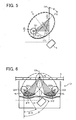
- Figure 1 shows a cross sectional view of a main portion of a xenon lamp 2 that has generally been used as a light source of a document illuminating unit.
- the xenon lamp 2 includes an opening or aperture 2a, a fluorescent material 2b, a lamp bulb or glass tube 2c, and electrodes 2d and 2e.
- the glass tube 2c has a transparent and cylindrical shape and a thickness of approximately 0.5 mm to approximately 1 mm.
- the electrodes 2d and 2e are disposed on a circumference of the glass tube 2c, facing each other.
- the xenon lamp 2 is filled with xenon gas and the electrodes 2d and 2e are applied with a predetermined amount (a several hundred) of an alternating voltage so that the light can be discharged from the xenon lamp 2.
- This discharge causes flows of electrons, which causes the electrons of xenon gas passing through the glass tube 2c to collide with the atoms of xenon gas in the glass tube 2c.
- This collision can generate ultraviolet rays.
- the ultraviolet rays illuminate the fluorescent-coated inner circumference of the glass tube 2b, the fluorescent material is excited to emit visible light rays.
- the visible light rays are emitted from the aperture 2a to the outside the fluorescent lamp 2.
- Figure 2 shows a conventional document illuminating unit utilizing the above-described xenon lamp as a light source to illuminate an original document.
- the conventional document illuminating unit of Figure 2 includes one xenon lamp and one reflection plate for illuminating its image reading area. A portion of luminous fluxes emitted from the xenon lamp travels through an opening or aperture (not shown) via the reflection plate to illuminate an original document placed on a contact glass. The other portion of luminous fluxes emitted from the xenon lamp directly illuminates the image reading area of the original document on the contact glass.
- the reflected luminous fluxes are directed to an image forming lens via first, second, and third mirrors (not shown) so that they can be ready as image data by an image reading unit such as a CCD (charge-coupled device) sensor.
- an image reading unit such as a CCD (charge-coupled device) sensor.
- Well known reflection plates have a surface with an elliptic shape, a paraboloidal shape, and so forth.
- a reflection plate corresponding to the lamp has a cylindrical shape.
- the reflection plate having a shape of an ellipse has two focal points, and a center of the fluorescent lamp is arranged at one of the two focal points, the focal point is located at a far side of the original document.
- the above-described conventional document illuminating unit suffers from the disadvantage that a high-speed full-color image scanner that has high productivity requires a large amount of light to illuminate a document.
- the xenon lamp 2 needs a greater area coated by fluorescent agent, which requires a greater diameter of the glass tube 2c so as to flow a greater amount of electric current. If the diameter of the glass tube 2c becomes greater in size, the area of the aperture 2a also becomes greater. This causes the reflection plate itself to have a greater size, which contributes to maximization of the document illuminating unit.
- the xenon lamp 2 since the xenon lamp 2 has a relatively large area of light emission and has the aperture 2a to emit luminous flux, it is difficult to collect the luminous flux to illuminate a document area.
- the luminous flux emitted for illuminating a document area A may illuminate as far as an area B. That is, the luminous flux illuminates a wider area than expected. Therefore, reflecting light rays of unnecessary luminous flux travel via a reflection plate and the xenon lamp 2 to illuminate the original document. That is, the original document is illuminated again.
- an amount of light emission may change according to a density of the original document.
- the density of an original document is substantially equal to an area coverage rate of the original document, which shows how much image data covers a reading area on the original document. For example, when an original document has a low area coverage, the density of the original document becomes lower, and when an original document has a high area coverage, the density of the original document becomes higher. That is, the conventional document illuminating unit has the disadvantage that a density value of scanned image data becomes more different from a density value of data of an original document, and the reproducibility of image may become worse. Further, the reproducibility of image also becomes worse even when the conventional document illuminating unit having a lamp generally with a large quantity of light is used.
- the present invention has been made in view of the above-described circumstances.
- An object of the present invention is to provide a novel document illuminating unit that can efficiently illuminate an original document with a large quantity of light and a low amount of flare by reducing unnecessary luminous flux and can downsize a reflection plate used in the novel document illuminating unit.
- Another object of the present invention is to provide a method of illuminating a document with light emitted from a light source via a reflection plate.
- a novel document illuminating unit includes at least one light source and at least one reflector.
- the at least one light source is configured to emit light and has an opening.
- the at least one reflector is configured to reflect the light emitted from the at least one light source.
- the opening is arranged at an obliquely downward portion of the at least one light source, the at least one reflector is disposed at a position obliquely downward the at least one light source, and the light emitted from the opening of the at least one light source travels via the at least one reflector to illuminate a document reading area.
- the at least one light source may include a fluorescent lamp, and the at least one reflector may have a shape of an ellipse to collect the light emitted from the at least one light source.
- One focal point of the reflector may be arranged in a straight line of a center of the fluorescent lamp and a center of the opening, and another focal point may be arranged in a vicinity of a reading position of a document.
- the at least one light source may include two fluorescent lamps configured to emit light respectively, and the at least one reflector may include two reflectors configured to reflect the light emitted from the respective fluorescent lamps.
- Each of the reflectors has a shape of an ellipse. Further, a cross point of major axes of the respective ellipses of the reflectors may be located at one of a first position inside a contact glass and a second position upper than the contact glass.
- the cross point of the major axes of the respective ellipses of the reflectors may be a focal point of the ellipses of the reflectors located on the document, and the following formula may be satisfied; D ⁇ cos ⁇ ⁇ H , where "D" represents a distance between the two focal points, " ⁇ ” represents a lean angle of the ellipse with respect to an optical axis in a direction of a plumb line to a document, and "H” represents a distance from a center of each of the fluorescent lamps to a lower surface of the contact glass.
- the at least one light source may include one fluorescent lamp configured to emit light
- the at least one reflector may include one reflector having a shape of an ellipse and configured to reflect the light emitted from the one fluorescent lamp, and a focal point of the ellipse of the reflector may be located at one of a first position inside a contact glass and a second position upper than the contact glass.
- the at least one light source may include two fluorescent lamps configured to emit light respectively, and the at least one reflector may include two reflectors configured to reflect the light emitted from the respective fluorescent lamps.
- Each of the reflectors may have a shape of an ellipse.
- one focal point of the reflector may be arranged in a straight line of a center of the fluorescent lamp and a center of the opening and another focal point may be arranged in a vicinity of a reading position of the document, and a cross point of major axes of the respective ellipses of the reflectors may be located at one of a first position inside a contact glass and a second position upper than the contact glass.
- the above-described novel document illuminating unit may be included in a document reading device.
- the above-described novel document illuminating unit may be included in an image forming apparatus.
- a novel method of illuminating a document with light emitted from a light source via a reflector includes emitting light from the light source to the reflector arranged at an obliquely downward position with respect to the light source, receiving the emitted light, and reflecting the emitted light to the document.
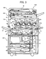
- the image forming apparatus 1000 of Figure 3 includes a main body 100, a sheet feeding table 200, an image scanner 300, and an automatic document feeder (ADF) 400.
- ADF automatic document feeder
- the main body 100 is disposed on the sheet feeding table 200.
- the image scanner 300 serves as an image reading device and is provided on the upper surface of the main body 100.
- the automatic document feeder 400 is provided on the top of the image scanner 300.
- the main body 100 can include four image forming units 18y, 18c, 18m, and 18bk as a tandem-type image forming mechanism 20, an intermediate transfer member 10 as a transfer mechanism, a writing unit 21 as a writing mechanism, a fixing unit 25 as a fixing mechanism, and a portion of a sheet feeding mechanism that is mainly disposed in the sheet feeding table 200.
- the four image forming units 18y, 18c, 18m, and 18bk of the tandem-type image forming mechanism 20 include four photoconductive elements 40y, 40c, 40m, and 40bk, respectively.
- the four photoconductive elements 40y, 40c, 40m, and 40bk can have similar structures and functions, except that the toners are different colors to form yellow images, magenta images, cyan images, and black images, respectively.
- the four image forming units 18y, 18c, 18m, and 18bk are separately arranged at positions having horizontal heights or elevations forming the tandem-type image forming mechanism 20.
- the photoconductive elements 40y, 40c, 40m, and 40bk separately receive respective light laser beams emitted by the writing unit 21, such that electrostatic latent images are formed on the respective surfaces of the four photoconductive elements 40y, 40c, 40m, and 40bk.
- Respective charging rollers (not shown) are held in contact with the photoconductive elements 40y, 40c, 40m, and 40bk to charge respective surfaces of the photoconductive elements 40y, 40c, 40m, and 40bk.
- Respective developing units 60y, 60c, 60m, and 60bk are separately disposed in a vicinity of or adjacent to the four image forming units 18y, 18c, 18m, and 18bk, respectively.
- the respective developing units 60y, 60c, 60m, and 60bk store the different colored toners for the image forming units 18y, 18c, 18m, and 18bk.
- the writing unit 21 is provided at a position above the tandem-type image forming mechanism 20.
- the writing unit 21 is provided at a position above the image forming units 18y, 18c, 18m, and 18bk.
- the writing unit 21 has four laser diodes (LDs), a polygon scanner, and lenses and mirrors.
- the four laser diodes (LDs) serve as light sources and irradiate the respective photoconductive elements 40m, 40c, 40y and 40bk with respective imagewise laser light beams to form electrostatic latent images thereon.
- the polygon scanner including a polygon mirror having plural surfaces and a polygon motor.
- Lenses such as f-theta lenses, elongate WTLs, and other lenses, and mirrors are provided in an optical path of the respective laser light beams.
- the laser light beams emitted from the laser diodes are deflected by the polygon scanner to irradiate the photoconductive elements 40m 40c, 40y and 40bk.
- the transfer mechanism which includes the intermediate transfer belt 10, is located or disposed below the tandem-type image forming mechanism 20 (substantially at the center of the image forming apparatus 1000).
- the intermediate transfer member 10 forms an endless belt and is passed over or surrounds a plurality of supporting rollers 14, 15, and 16.
- the intermediate transfer member 10 is held in contact with the photoconductive elements 40y, 40c, 40m, and 40bk, and is driven to rotate clockwise as indicated by an arrow as shown in Figure 3.
- an intermediate transfer member cleaning unit 17 is provided in the left side of the supporting roller 15.
- the intermediate transfer member cleaning unit 17 removes a residual toner on the intermediate transfer member 10 after image formation.
- Four primary transfer unit 65y, 65c, 65m, and 65bk are disposed inside a loop of the intermediate transfer member 10 to face the respective photoconductive elements 40y, 40c, 40m, and 40bk, which are accommodated in the image forming units 18y, 18c, 18m, and 18bk.
- a secondary transfer unit 22 is located on the opposite side of the intermediate transfer member 10 from the tandem type image forming mechanism 20.
- the secondary transfer unit 22 includes a secondary transfer belt 24 that is an endless belt, and the transfer belt 24 is extended between two secondary transfer rollers 23a and 23b.
- the secondary transfer unit 22 is arranged such that a portion of the secondary transfer belt 24, which is close to the secondary transfer roller 23a, presses the intermediate transfer member 10 against the supporting roller 16.
- the fixing unit 25 is positioned at a lower left side of the main body 100, in a vicinity of the secondary transfer roller 23b and below the supporting roller 15.
- the fixing unit 25 includes a fixing belt 26 and a pressure roller 27, and is configured to press the pressure roller 27 against the fixing belt 26 that is an endless belt
- the secondary transfer unit 22 also serves as a sheet transport mechanism for transporting a recording sheet having a color toner image thereon to the fixing unit 25.
- a transfer roller or a non-contact transfer charging unit may be used as an alternative to the secondary transfer unit 22. In a case in which the transfer roller or the non-contact transfer charging unit is used, however, it is preferable to separately provide a sheet transport mechanism for transporting a recording sheet having a color toner image thereon to the fixing unit 25.
- the main body 100 is further provided with a sheet reverse unit 28 for reversing a recording sheet on one side of which an image is formed. Another image can be formed on the other side of the recording sheet for a duplex image forming operation in a duplex copy mode.
- the sheet reverse unit 28 is arranged under the secondary transfer unit 22 and the fixing unit 25, and is substantially parallel to the tandem-type image forming mechanism 20.
- the main body 100 includes several components, such as a sheet transporting passage 48 and a pair of registration rollers 49 serving as the sheet feeding mechanism, which will be described below, the sheet feeding mechanism is mainly arranged in the sheet feeding table 200.
- the sheet feeding table 200 serving as the sheet feeding mechanism, is arranged in a lower portion of the image forming apparatus 1000, and includes: sheet feeding rollers 42a, 42b, and 42c; a sheet bank 43; sheet feeding cassettes 44a, 44b, and 44c; sheet separation rollers 45a, 45b, and 45c; a sheet transporting passage 46; and a plurality of sheet feeding rollers 47.
- the sheet feeding cassettes 44a, 44b and 44c are provided to the sheet bank 43 and are loaded with a stack of sheets of particular size, including a recording sheet (not shown).
- a recording sheet (not shown).
- the recording sheet is fed from one of the sheet feeding cassettes 44a, 44b, and 44c and is conveyed toward the pair of registration rollers 49.
- the sheet feeding mechanism also includes a manual sheet feeding tray 51, a switch pawl 55, a pair of sheet discharging rollers 56, and a sheet discharging tray 57.
- the manual sheet feeding tray 51 is mounted on the right side of the main body 100 of Figure 3, and includes sheet inlet rollers 50, sheet separation rollers 52 and a manual sheet transporting passage 53. After opening the manual sheet feeding tray 51, an operator of the image forming apparatus 1000 may feed sheets by hand.
- the image scanner 300 includes an original document stacker 30 and a contact glass 3.
- the image scanner 300 also includes first and second moving units 31 and 32, an image forming lens 33, and an image reading sensor 34.
- a set of original documents are placed in a face-up orientation on the original document stacker 30 of the ADF 400.
- the set of original documents can manually be placed sheet by sheet directly on the contact glass 3 of the image scanner 300.
- an operator lifts up the ADF 400 having a shell-like openable structure.
- the operator lowers the ADF 400 to a closing position, thereby an entire surface of the original document placed on the contact glass 3 may be pressed by a lower surface of the ADF 400.
- a start button (not shown) is pressed, an uppermost sheet of the set of original documents placed on the ADF 400 is separated and is transported to the contact glass 3 of the image scanner 300 and, subsequently, the image scanner 300 is activated. That is, the first and second moving units 31 and 32 of the image scanner 300 slide in a predetermined direction.
- the image scanner 300 is immediately activated upon the press of the start button.
- the first moving unit 31 is a document lighting unit 31, and includes light sources 121 and 122, reflection plates 111 and 112 (see Figure 4), and a first mirror 4.
- the second moving unit 32 includes second and third mirrors (not shown).
- the first moving unit or the document lighting unit 31 causes a light beam to emit and deflects the light beam reflected by the original document placed on the contact glass 3.
- the second moving unit 32 receives the light beam reflected by the mirror or the first moving unit 33 and reflects the light beam to the image reading sensor 34 via the image forming lens 33.
- one of the supporting rollers 14, 15, and 16 is driven by a drive motor (not shown) to rotate the other two rollers.
- This causes the intermediate transfer member 10 to rotate.
- the image forming units 18y, 18c, 18m, and 18bk are driven to rotate the corresponding photoconductive elements 40y, 40c, 40m, and 40bk.
- This forms single color images in yellow, cyan, magenta, and black on the respective photoconductive elements 40y, 40c, 40m, and 40bk in the image forming mechanism 20.
- each of the photoconductive elements 40y, 40c, 40m, and 40bk rotates in a counterclockwise direction in Figure 3 and are uniformly charged with corresponding charging rollers (not shown) included in respective charging units (not shown).
- the writing unit 21 emits the light beams corresponding to the respective color image data and irradiates the photoconductive elements 40y, 40c, 40m, and 40bk of the image forming units 18y, 18c, 18m, and 18bk, respectively.
- Electrostatic latent images corresponding to the respective color image data are formed on respective surfaces of the photoconductive elements 40y, 40c, 40m, and 40bk.
- the electrostatic latent images formed on the respective photoconductive elements 40y, 40c, 40m, and 40bk are visualized by the respective developing units 60y, 60c, 60m, and 60bk, which contain respective color toners therein, into yellow, cyan, magenta, and black toner images, respectively.
- Those color toner images are sequentially overlaid on the surface of the intermediate transfer member 10 such that a composite color image is formed on the surface of the intermediate transfer member 10.
- the sheet feeding roller 42a starts to rotate so that the recording sheet is conveyed to the sheet separation roller 45a in the sheet feeding cassette 44a.
- the sheet separation roller 45a separates the recording sheet from the following sheets and transfers the recording sheet to the sheet transporting passage 46.
- the recording sheet S is conveyed by the plurality of sheet feeding rollers 47 through the sheet transporting passage 48 to the pair of registration rollers 49.
- the sheet inlet roller 50 is rotated to feed a set of recording sheets placed on the manual sheet feeding tray 51 to the pair of sheet separation rollers 52. Then, the pair of sheet separation rollers 52 separate an uppermost recording sheet from the set of recording sheets placed on the manual sheet feeding tray 51 and transfers the uppermost recording sheet, which will be referred to as the recording sheet, to the pair of registration rollers 49 through the manual sheet transporting passage 53.
- the pair of registration rollers 49 stops and feeds the recording sheet in synchronization with a movement of the composite color image towards a transfer area formed between the intermediate transfer member 10 and the secondary transfer unit 22.
- the transfer area is formed between a portion where the intermediate transfer member 10 is supported by the supporting roller 16 and a portion where the secondary transfer unit 22 is supported by the secondary transfer roller 23a.
- the composite color image formed on the surface of the intermediate transfer member 10 is transferred onto the recording sheet at the transfer area.
- the recording sheet that has the composite color image thereon is further conveyed and passes through the fixing unit 25.
- the fixing unit 25 fixes the composite color image to the recording sheet by applying heat and pressure.
- the recording sheet may be sent to the sheet reverse unit 28 when the switch pawl 55 selects a sheet transporting passage (not shown) for the duplex image forming operation.
- the sheet reverse unit 28 receives the recording sheet, which on one side an image is formed. Another recording sheet is fed to the sheet reverse unit 28 after the recording sheet is switched back to the face-down orientation at the sheet transporting passage of the sheet reverse unit 28.
- the sheet reverse unit 28 then transports the recording sheet via the sheet transporting passage 48 to the pair of registration rollers 49 to pass through the transfer area formed between the intermediate transfer member 10 and the secondary image transfer unit 22 so that a next composite color image is transferred onto the back surface of the recording sheet.
- the recording sheet having composite color images printed on the front and back sides, is conveyed to the fixing unit 25.
- the recording sheet passes through the fixing unit 25, the recording sheet passes through a discharging passage selected by the switch pawl 55 and is discharged to a sheet discharging tray 57 via a pair of sheet discharging rollers 56.
- the intermediate transfer member cleaning unit 17 removes residual toner on the surface of the intermediate transfer member 10 before a next image forming operation.
- the supporting roller 15 When the image forming apparatus 1000 receives a command to produce black and white copies according to black and white image data, the supporting roller 15 is moved downward, thereby separating the image transfer belt 10 from the photoconductive elements 40y, 40c and 40m.
- the photoconductive element 40bk of the image forming unit 18bk rotates in the counterclockwise direction in Figure 3 to be uniformly charged with the corresponding charging roller (not shown). Then an imagewise laser light beam corresponding to the black and white image data irradiates the photoconductive element 40bk, resulting in formation of an electrostatic latent image on the photoconductive element 40bk.
- the electrostatic latent image formed on a surface of the photoconductive element 40bk is developed with the black developing device 60bk, resulting in formation of a black toner image on the photoconductive element 40bk.
- the image forming units 18y, 18c and 18m, the photoconductive elements 40y, 40c, and 40bk, and the developing units 60y, 60c and 60m are not activated. Therefore, undesired abrasion of the photoconductive elements 40m, 40c and 40y and undesired consumption of the toners other than the black toner can be prevented.
- the recording sheet is fed from one of the sheet feeding cassettes 44a, 44b, and 44c, to the image forming unit 18bk in synchronization with the pair of registration rollers 49 such that the black toner image formed on the photoconductive element 40bk is transferred to a proper position of the recording sheet.
- the recording sheet Since the recording sheet is fed while the recording paper is attracted by the image transfer belt 10, the recording sheet can be fed to the photoconductive element 40bk even when the photoconductive elements 40m, 40c and 40y are separated from the image transfer belt 10, resulting in formation of the black color image on the recording sheet.
- the recording sheet having the black toner image on the surface is discharged.
- the image forming operation described above is repeated.
- the image forming apparatus 1000 including the image scanner 300 has the structures and functions and performs the operations as described above.
- the structures, functions, and operations of the image forming apparatus 1000 of the present invention are not limited to those described above.
- the image forming apparatus 1000 according to the present invention can include one image bearing member for a plurality of developing units with an intermediate transferring system.
- the image forming apparatus according to the present invention also can be an image forming apparatus that performs black and white image forming but not color image forming.
- FIG 4 is a cross sectional view of the document illuminating unit 31 according to the present invention.
- the document illuminating unit 31 includes two fluorescent lamps 121 and 122, first and second reflection plates 111 and 112.
- the two fluorescent lamps 121 and 122 serving as a light source can be a xenon lamp, having a cylindrical shape in its major axis.
- the fluorescent lamps 121 and 122 have respective openings or apertures 121a and 122a.
- the apertures 121a and 122a are arranged at an obliquely downward portion of the fluorescent lamps 121 and 122, respectively.
- the first and second reflection plates 111 and 112 have a shape of an ellipse.
- the first reflection plate 111 is disposed at a position obliquely downward the fluorescent lamp 121.
- the second reflection plate 112 is disposed at a position obliquely downward the fluorescent lamp 122.
- the first reflection plates 111 corresponding to the fluorescent lamp 121 and the second reflection plate 112 corresponding to the fluorescent lamp 122 collect the respective luminous fluxes to illuminate a document reading area of the contact glass 3 on which an original document is placed.
- one focal point of an ellipse of the reflection plate 111 is arranged in a straight line of the center of the fluorescent lamp 121 and the center of the aperture 121a and another focal point is arranged in a vicinity of a reading position of an original document
- one focal point of an ellipse of the reflection plate 112 is arranged on a straight line extending from the center of the fluorescent lamp 122 to the center of the aperture 122a and another focal point is arranged in a vicinity of a reading position of an original document.
- the structure of the document illuminating unit 31 shown in Figure 4 has the two fluorescent lamps 121 and 122 and the two reflection plates 111 and 112.
- one fluorescent lamp and one reflection plate can be applied to the document illuminating unit 31 of the present invention.
- the reflection plates 111 and 112 and the fluorescent lamps 121 and 122 shown in Figure 4 are symmetrically disposed, sandwiching an optical axis OA in a direction of a plumb line from the reflection mirror 4 to an original document. Since the reflection plates 111 and 112 have similar structures and functions to each other and the fluorescent lamps 121 and 122 also have similar structures and functions to each other, the reflection plate 111 and the fluorescent lamp 121 are described below.
- the reflection plate 111 has the shape of an ellipse.
- a major axis of the ellipse of the reflection plate 111 is represented as a coordinate "X” and a minor axis of the ellipse of the reflection plate 111 is represented as a coordinate "Y”
- a center of the fluorescent lamp 121 having a radius "R" is arranged at one of two focal points of the ellipse.
- the focal point is located at a far side of the original document.
- Another focal point is arranged to be located in the vicinity of a reading position of the original document.
- a solid line drawn on the circumference mainly drawn by an alternate short and long dashed line in Figure 4 represents the reflection plate 111.
- angle " ⁇ ” satisfies the formula: ⁇ > sin - 1 ( R / D ) , where "D" represents a distance between the two focal points, and “R” represents the radius of the fluorescent lamp 121.
- the aperture 121a of the fluorescent lamp 121 is arranged at an obliquely downward portion on a circumference of the fluorescent lamp 121 and is configured to output light therethrough.
- the light emitting angle of the aperture 121a is arranged and directed to face the opposite side to the original document and also to face the optical axis OA in the plumb line from the reflection mirror 4 to the original document.
- the structure and formulas described above for the reflection plate 111 and the fluorescent lamp 121 can also be applied to the reflection plate 112 and the fluorescent lamp 122.
- a shaded area 5 shown in Figure 4 shows a range of light rays or luminous fluxes that is used to effectively illuminate the original document. Since the aperture 121a of the fluorescent lamp 121 is facing the opposite side to the original document, light passing through a slit 6 and shining directly on the reflection mirror 4 can be ambient light to adversely affect the reproducibility of image of the original document.
- the reflection plate 111 has a shape extending for a sufficient length to a direction of the optical axis OA in the direction of the plumb line to the original document from the reflection mirror 4 to reduce the negative effect due to ambient light. That is, the reflection plates 111 and 112 have a shape to function to avoid the direct incident light from the fluorescent lamps 112 and 122, respectively, on the reflection mirror 4. Moreover, the size of the reflection plate 111 is determined so as not to cover a distance S of the slit 6.
- the document illuminating device of Figure 6 includes two reflection plates 211 and 212 having respective shapes of an ellipse while the document illuminating device of Figure 4 is described for one fluorescent lamp.
- one focal point "fa” is arranged at a position on the optical axis OA in the direction of the plumb line to the original document and in the vicinity of the original document to be illuminated.
- Another focal point is located at a cross point "fb" of a fluorescent lamp 221 on a straight line extending from the center of the fluorescent lamp 221 to the center of an opening or aperture 221a on the circumference of a tube of the fluorescent lamp 221 with an angle " ⁇ /2”.
- Another focal point is located at a cross point "fc" of a fluorescent lamp 222 on a straight line extending from the center of the fluorescent lamp 222 to the center of an opening or aperture 222a on the circumference of a tube of the fluorescent lamp 222.
- FIG. 7 a side view showing another embodiment of the document illuminating unit 31 according to the present invention.
- the document illuminating unit 31 includes two fluorescent lamps 321 and 322 and two reflection plates 311 and 312 that respectively correspond to the fluorescent lamps 321 and 322.
- Each of the reflection plates 311 and 312 has a shape of an ellipse.
- the structures and functions of the fluorescent lamps 321 and 322 are identical to each other, and the structures and functions of the reflection plates 311 and 312 are also identical to each other. While the fluorescent lamp 321 has an opening or aperture 321a in Figure 7, the fluorescent lamp 322 also has an opening or aperture that is not shown in Figure 7.
- the fluorescent lamps 321 and 322 used in Figure 7 are a xenon lamp that illuminates an area, and therefore, the light rays illuminating the original document are not converged to a focal point.
- a graph shows distances from a surface of the original document to an upper surface of the contact glass 3 included in the image scanner 300 of Figure 3 and the amounts of fluctuation of image data.
- optical system 1 shows the amount of fluctuation of image data read by a conventional optical system
- optical system 2 shows the amount of fluctuation of image data read by a proposed optical system according to the present invention.
- the document illuminating unit 31 when the document illuminating unit 31 according to the present invention has at least one of the fluorescent lamps 121 and 122 and at least one of the reflection plates 111 and 112 corresponding to the fluorescent lamps 121 and 122, respectively, the document illuminating unit 31 can reduce the amount of fluctuation of image data having a distance between the contact glass 3 and the original document to 1/3 or less of the amount of fluctuation of image data for a conventional document illuminating unit.
- the document illuminating unit 31 includes the fluorescent lamps 121 and 122, each of which has a cylindrical shape in its major axis, and have the apertures 121a and 122a arranged at an obliquely downward portion of the fluorescent lamps 121 and 122, respectively.
- the document illuminating unit 31 also includes the first and second reflection plates 111 and 112 having a shape of an ellipse.
- the reflection plate 111 is disposed at a position obliquely downward the fluorescent lamp 121
- the second reflection plate 112 is disposed at a position obliquely downward the fluorescent lamp 122.
- the first reflection plates 111 corresponding to the fluorescent lamp 121 and the second reflection plate 112 corresponding to the fluorescent lamp 122 collect the respective luminous fluxes to illuminate a document reading area of the contact glass 3 on which an original document is placed.
- the document illuminating unit 31 can not adversely be affected by a reflection density of the original document, and can reduce the amount of unnecessary light for illuminating the original document and efficiently illuminate the original document.
- one focal point is arranged to a center of the fluorescent lamps 121 or 122 having the radius R, and another focal point is arranged to be located in the vicinity of the reading position of the original document.
- the light emitting angle of each of the apertures 121a and 122a is arranged and directed to face the opposite side to the original document and also to face the optical axis OA in the plumb line from the reflection mirror 4 to the original document.
- one focal point is arranged to the center of the fluorescent lamps 121 or 122 having the radius R, and another focal point is arranged to be located in the vicinity of the reading position of the original document.
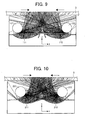
- FIGs 9 and 10 schematic views show estimated beam lines of light of the document illuminating apparatus 31 of Figures 4 and 6, respectively.
- one focal point of the ellipse of each of the reflection plates 111 and 112 is located at the center of each of the fluorescent lamps 121 (corresponding to the reflection plate 111) and 122 (corresponding to the reflection plate 112) and another focal point is located on the original document to be illuminated.
- one focal point of the reflection plate 211 is located at a cross point "fb" of the fluorescent lamp 221 on a straight line extending from the center of the fluorescent lamp 221 to the center of the aperture 221a on the circumference of a tube of the fluorescent lamp 221 with an angle " ⁇ /2".
- one focal point is located at a cross point "fc" of the fluorescent lamp 222 on a straight line extending from the center of the fluorescent lamp 222 to the center of the aperture 222a on the circumference of a tube of the fluorescent lamp 222.
- another focal point "fa” is arranged on the original document to be illuminated on the optical axis OA in the direction of the plumb line to the original document.
- coordinates "x” and “y” in Figures 9 and 10 are used for simulations to obtain the estimated beam lines of light of the document illuminating apparatus 31.
- the coordinate "x” indicates a direction of a plumb line of light traveling in the document illuminating unit 31, and the coordinate "y” indicates a direction of a horizontal line of the light.
- the light rays or luminous fluxes emitted from the fluorescent lamps 221 and 222 of the document illuminating unit 31 of Figure 10 are more collected at the reading position of the original document than the light rays or luminous flux emitted from the fluorescent lamps 121 and 122 of the document illuminating unit 31 of Figure 9.
- the areas of the ellipses of the reflecting plates 211 and 212 of Figure 10 can be arranged smaller so as to fit in a relatively small space in a downsized document illuminating unit 31.
- the reflection plates 111 and 112 and the fluorescent lamps 121 and 122 in Figure 9 and the reflection plates 211 and 212 and the fluorescent lamps 221 and 222 in Figure 10 are symmetrically disposed, both sandwiching the optical axis OA in the direction of the plumb line from the reflection mirror 4 to the original document.
- the above-described structure can cause the document illuminating unit 31 to uniformly emit the reading area of the original document from the fluorescent lamps 121, 122, 212, and 222. Thereby, it is possible to avoid shading problems caused by curling of the original document when the original document is relatively small.
- a cross point of the major axes of the respective ellipses of the reflection plates 111 and 112 is located at a position inside or upper than the contact glass 3.
- the cross point of the major axes of the respective ellipses of the reflection plates 111 and 112 is a focal point of the ellipses of the reflection plates 111 and 112 located on the original document, and is expressed by the following formula; D • cos ⁇ ⁇ H , where "D" represents a distance between the two focal points, " ⁇ ” represents a lean angle of the ellipse with respect to the optical axis OA in the direction of the plumb line from the reflection mirror 4 to the original document, and "H” represents a distance from the center of each of the fluorescent lamps 121 and 122 to a lower surface of the contact glass 3.
- the apex of the area on which the light rays emitted from the fluorescent lamps 121 and 122 are traveling across each other is arranged at an upper portion than the original document placed on the upper surface of the contact glass 3 so that the brightest area can be used for illuminating the original document. That is, as shown in Figure 8, the original document having a distance above 0 mm from the contact glass 3 can be illuminated at the brightness substantially equal to the original document closely placed on the upper surface the contact glass 3.
- the fluctuation of light rays or luminous fluxes can be reduced and the density or the area coverage rate of an original document can have less difference from the density or the area coverage rate of the image data obtained from the original document.
- the document illuminating unit 31 of the present invention can simultaneously satisfy the structures and functions as described above. Since the apertures 121a and 122a of the fluorescent lamps 121 and 122 in this embodiment are facing the opposite side of the original document, the incident of flare can be reduced, and therefore, an appropriate ellipse shape to forming the light rays emitted from the fluorescent lamps 121 and 122 to the convergent luminous fluxes.
- the document illuminating unit 31 of the present invention can arrange the reflection plates 111 and 112 to have a shape that can avoid the direct incident light from the fluorescent lamps 112 and 122, respectively, on the reflection mirror 4.
- the document illuminating unit 31 can reduce the amount of unnecessary light for illuminating the original document and efficiently illuminate the original document.
Landscapes
- Engineering & Computer Science (AREA)
- Multimedia (AREA)
- Signal Processing (AREA)
- Facsimile Scanning Arrangements (AREA)
- Light Sources And Details Of Projection-Printing Devices (AREA)
Abstract
Description
- The present invention relates to a method and apparatus for illuminating a document. More particularly, the present invention relates to a document illuminating unit, using a fluorescent lamp serving as a light source, that can efficiently illuminate an original document with a large quantity of light and a low amount of flare, and an image scanner utilizing the document illuminating unit, and an image forming apparatus such as a copier, printer, facsimile machine, and a multi-functional machine including the functions of the copier, printer, facsimile machine, and so forth, the image forming apparatus including the image scanner with the document illuminating unit.
- It is well known that an image scanner included in an image forming apparatus generally employs a xenon lamp, having a diameter of approximately 10 mm, as a fluorescent lamp. The xenon lamp has brightness smaller than a halogen lamp but has a greater amount of light emission because the xenon lamp has a greater area for emitting visible light rays, and also has higher luminous efficiency with respect to electric power consumption. Further, the amount of light emission of the xenon lamp is substantially proportional to an area covered with fluorescent coating. Therefore, the amount of light emission of the xenon lamp increases when a diameter of a glass tube of the xenon lamp is increased and fluorescent coating is applied to a wider area of the xenon lamp. However, a greater diameter of the glass tube requires a greater size of the document illuminating unit, and a greater size of an image scanner.
- Figure 1 shows a cross sectional view of a main portion of a
xenon lamp 2 that has generally been used as a light source of a document illuminating unit. In Figure 1, thexenon lamp 2 includes an opening oraperture 2a, afluorescent material 2b, a lamp bulb orglass tube 2c, andelectrodes glass tube 2c has a transparent and cylindrical shape and a thickness of approximately 0.5 mm to approximately 1 mm. Theelectrodes glass tube 2c, facing each other. Thexenon lamp 2 is filled with xenon gas and theelectrodes xenon lamp 2. This discharge causes flows of electrons, which causes the electrons of xenon gas passing through theglass tube 2c to collide with the atoms of xenon gas in theglass tube 2c. This collision can generate ultraviolet rays. When the ultraviolet rays illuminate the fluorescent-coated inner circumference of theglass tube 2b, the fluorescent material is excited to emit visible light rays. The visible light rays are emitted from theaperture 2a to the outside thefluorescent lamp 2. - Figure 2 shows a conventional document illuminating unit utilizing the above-described xenon lamp as a light source to illuminate an original document. The conventional document illuminating unit of Figure 2 includes one xenon lamp and one reflection plate for illuminating its image reading area. A portion of luminous fluxes emitted from the xenon lamp travels through an opening or aperture (not shown) via the reflection plate to illuminate an original document placed on a contact glass. The other portion of luminous fluxes emitted from the xenon lamp directly illuminates the image reading area of the original document on the contact glass. After these luminous fluxes are reflected, the reflected luminous fluxes are directed to an image forming lens via first, second, and third mirrors (not shown) so that they can be ready as image data by an image reading unit such as a CCD (charge-coupled device) sensor.
- Well known reflection plates have a surface with an elliptic shape, a paraboloidal shape, and so forth. When a lamp serving as a light source has a columnar shape, it is well known a reflection plate corresponding to the lamp has a cylindrical shape.
- Further, the reflection plate having a shape of an ellipse has two focal points, and a center of the fluorescent lamp is arranged at one of the two focal points, the focal point is located at a far side of the original document.
- The above-described conventional document illuminating unit suffers from the disadvantage that a high-speed full-color image scanner that has high productivity requires a large amount of light to illuminate a document. To obtain a large quantity of light, however, the
xenon lamp 2 needs a greater area coated by fluorescent agent, which requires a greater diameter of theglass tube 2c so as to flow a greater amount of electric current. If the diameter of theglass tube 2c becomes greater in size, the area of theaperture 2a also becomes greater. This causes the reflection plate itself to have a greater size, which contributes to maximization of the document illuminating unit. - Further, since the
xenon lamp 2 has a relatively large area of light emission and has theaperture 2a to emit luminous flux, it is difficult to collect the luminous flux to illuminate a document area. For example, as shown in Figure 2, the luminous flux emitted for illuminating a document area A may illuminate as far as an area B. That is, the luminous flux illuminates a wider area than expected. Therefore, reflecting light rays of unnecessary luminous flux travel via a reflection plate and thexenon lamp 2 to illuminate the original document. That is, the original document is illuminated again. When the reflecting light rays have has a large quantity of light, an amount of light emission may change according to a density of the original document. The density of an original document is substantially equal to an area coverage rate of the original document, which shows how much image data covers a reading area on the original document. For example, when an original document has a low area coverage, the density of the original document becomes lower, and when an original document has a high area coverage, the density of the original document becomes higher. That is, the conventional document illuminating unit has the disadvantage that a density value of scanned image data becomes more different from a density value of data of an original document, and the reproducibility of image may become worse. Further, the reproducibility of image also becomes worse even when the conventional document illuminating unit having a lamp generally with a large quantity of light is used. - The present invention has been made in view of the above-described circumstances.
- An object of the present invention is to provide a novel document illuminating unit that can efficiently illuminate an original document with a large quantity of light and a low amount of flare by reducing unnecessary luminous flux and can downsize a reflection plate used in the novel document illuminating unit.
- Another object of the present invention is to provide a method of illuminating a document with light emitted from a light source via a reflection plate.
- In one embodiment, a novel document illuminating unit includes at least one light source and at least one reflector. The at least one light source is configured to emit light and has an opening. The at least one reflector is configured to reflect the light emitted from the at least one light source. The opening is arranged at an obliquely downward portion of the at least one light source, the at least one reflector is disposed at a position obliquely downward the at least one light source, and the light emitted from the opening of the at least one light source travels via the at least one reflector to illuminate a document reading area.
- The at least one light source may include a fluorescent lamp, and the at least one reflector may have a shape of an ellipse to collect the light emitted from the at least one light source.
- One focal point of the reflector may be arranged in a straight line of a center of the fluorescent lamp and a center of the opening, and another focal point may be arranged in a vicinity of a reading position of a document.
- The reflector may be expressed by following formulas;


where "X" represents a major axis of the ellipse, "Y" represents a minor axis of the ellipse, "θ" represents a lean angle of the ellipse with respect to an optical axis in a direction of a plumb line to an document, "α represents an angle between the major axis of the ellipse and a nearest light ray to the document, "β" represents a light convergent angle, "γ" represents an angle between a farthest light ray from the document and the optical axis in the direction of the plumb line to the document, "R" represents a radius of the fluorescent lamp, and "D" represents a distance between two focal points. - The reflector may be expressed by following formulas;


- The at least one light source may include two fluorescent lamps configured to emit light respectively, and the at least one reflector may include two reflectors configured to reflect the light emitted from the respective fluorescent lamps. Each of the reflectors has a shape of an ellipse. Further, a cross point of major axes of the respective ellipses of the reflectors may be located at one of a first position inside a contact glass and a second position upper than the contact glass.
- The cross point of the major axes of the respective ellipses of the reflectors may be a focal point of the ellipses of the reflectors located on the document, and the following formula may be satisfied;

- The at least one light source may include one fluorescent lamp configured to emit light, and the at least one reflector may include one reflector having a shape of an ellipse and configured to reflect the light emitted from the one fluorescent lamp, and a focal point of the ellipse of the reflector may be located at one of a first position inside a contact glass and a second position upper than the contact glass.
- The at least one light source may include two fluorescent lamps configured to emit light respectively, and the at least one reflector may include two reflectors configured to reflect the light emitted from the respective fluorescent lamps. Each of the reflectors may have a shape of an ellipse. The reflector may be expressed by following formulas;


- The above-described novel document illuminating unit may be included in a document reading device.
- The above-described novel document illuminating unit may be included in an image forming apparatus.
- Further, in one embodiment, a novel method of illuminating a document with light emitted from a light source via a reflector includes emitting light from the light source to the reflector arranged at an obliquely downward position with respect to the light source, receiving the emitted light, and reflecting the emitted light to the document.
- A more complete appreciation of the disclosure and many of the attendant advantages thereof will be readily obtained as the same becomes better understood by reference to the following detailed description when considered in connection with the accompanying drawings, wherein:
- Figure 1 is a cross sectional view of a main portion of a xenon lamp generally used as a light source;
- Figure 2 is a cross sectional view of a conventional document illuminating unit utilizing the xenon lamp of Figure 1;
- Figure 3 is a schematic structure of an image forming apparatus including an image scanner having a document illuminating unit according to an exemplary embodiment of the present invention;
- Figure 4 is a side view showing a schematic structure of an exemplary embodiment of the document illuminating unit according to the present invention;
- Figure 5 is a side view of an ellipse of a reflector and a fluorescent lamp of Figure 4;
- Figure 6 is a side view of another embodiment of the document illuminating unit according to the present invention;
- Figure 7 is a side view showing another embodiment of the document illuminating unit according to the present invention;
- Figure 8 is a graph showing distances from a surface of the original document to an upper surface of a contact glass included in an image scanner and amounts of fluctuation of image data;
- Figure 9 is a schematic view showing estimated beam lines of light of the document illuminating unit of Figure 4; and
- Figure 10 is a schematic view showing estimated beam lines of light of the document illuminating unit of Figure 6.
- In describing preferred embodiments illustrated in the drawings, specific terminology is employed for the sake of clarity. However, the disclosure of this patent specification is not intended to be limited to the specific terminology so selected and it is to be understood that each specific element includes all technical equivalents that operate in a similar manner.
- The features relating to the present invention and described with reference to the drawings attached to the present patent application and discussed in the specification can be used in connection with the different embodiments although such features are only disclosed in connection with one of the embodiments. In particular, it is possible to use the features disclosed in the claims in combination with the different embodiments disclosed in the specification. In particular, it is possible to exchange one or several features of one embodiment with those of another embodiment or to supplement one embodiment with features of another embodiment.
- Referring now to the drawings, wherein like reference numerals designate identical or corresponding parts throughout the several views, preferred embodiments of the present invention are described.
- Referring to Figure 3, a structure of a
image forming apparatus 1000 including animage scanner 300 having adocument illuminating unit 31 according to an exemplary embodiment of the present invention is now described. - The
image forming apparatus 1000 of Figure 3 includes amain body 100, a sheet feeding table 200, animage scanner 300, and an automatic document feeder (ADF) 400. - The
main body 100 is disposed on the sheet feeding table 200. Theimage scanner 300 serves as an image reading device and is provided on the upper surface of themain body 100. Theautomatic document feeder 400 is provided on the top of theimage scanner 300. - In Figure 3, the
main body 100 can include fourimage forming units image forming mechanism 20, anintermediate transfer member 10 as a transfer mechanism, awriting unit 21 as a writing mechanism, a fixingunit 25 as a fixing mechanism, and a portion of a sheet feeding mechanism that is mainly disposed in the sheet feeding table 200. - The four
image forming units image forming mechanism 20 include fourphotoconductive elements photoconductive elements - The four
image forming units image forming mechanism 20. Thephotoconductive elements writing unit 21, such that electrostatic latent images are formed on the respective surfaces of the fourphotoconductive elements - Respective charging rollers (not shown) are held in contact with the
photoconductive elements photoconductive elements - Respective developing
units image forming units units image forming units - The
writing unit 21 is provided at a position above the tandem-typeimage forming mechanism 20. Thewriting unit 21 is provided at a position above theimage forming units writing unit 21 has four laser diodes (LDs), a polygon scanner, and lenses and mirrors. The four laser diodes (LDs) serve as light sources and irradiate the respectivephotoconductive elements photoconductive elements 40m - The transfer mechanism, which includes the
intermediate transfer belt 10, is located or disposed below the tandem-type image forming mechanism 20 (substantially at the center of the image forming apparatus 1000). Theintermediate transfer member 10 forms an endless belt and is passed over or surrounds a plurality of supportingrollers intermediate transfer member 10 is held in contact with thephotoconductive elements - In Figure 3, an intermediate transfer
member cleaning unit 17 is provided in the left side of the supporting roller 15. The intermediate transfermember cleaning unit 17 removes a residual toner on theintermediate transfer member 10 after image formation. - Four
primary transfer unit intermediate transfer member 10 to face the respectivephotoconductive elements image forming units - A
secondary transfer unit 22 is located on the opposite side of theintermediate transfer member 10 from the tandem typeimage forming mechanism 20. Thesecondary transfer unit 22 includes asecondary transfer belt 24 that is an endless belt, and thetransfer belt 24 is extended between twosecondary transfer rollers secondary transfer unit 22 is arranged such that a portion of thesecondary transfer belt 24, which is close to thesecondary transfer roller 23a, presses theintermediate transfer member 10 against the supportingroller 16. When a recording sheet is conveyed to a portion between the supportingroller 16 and thesecondary transfer roller 23a of thesecondary transfer belt 24, an overlaid color toner image formed on the surface of theintermediate transfer member 10 is transferred onto the recording sheet. - The fixing
unit 25 is positioned at a lower left side of themain body 100, in a vicinity of thesecondary transfer roller 23b and below the supporting roller 15. The fixingunit 25 includes a fixingbelt 26 and apressure roller 27, and is configured to press thepressure roller 27 against the fixingbelt 26 that is an endless belt - The
secondary transfer unit 22 also serves as a sheet transport mechanism for transporting a recording sheet having a color toner image thereon to the fixingunit 25. As an alternative to thesecondary transfer unit 22, a transfer roller or a non-contact transfer charging unit may be used. In a case in which the transfer roller or the non-contact transfer charging unit is used, however, it is preferable to separately provide a sheet transport mechanism for transporting a recording sheet having a color toner image thereon to the fixingunit 25. - In the
image forming apparatus 1000 of Figure 3, themain body 100 is further provided with a sheetreverse unit 28 for reversing a recording sheet on one side of which an image is formed. Another image can be formed on the other side of the recording sheet for a duplex image forming operation in a duplex copy mode. The sheetreverse unit 28 is arranged under thesecondary transfer unit 22 and the fixingunit 25, and is substantially parallel to the tandem-typeimage forming mechanism 20. - While the
main body 100 includes several components, such as asheet transporting passage 48 and a pair ofregistration rollers 49 serving as the sheet feeding mechanism, which will be described below, the sheet feeding mechanism is mainly arranged in the sheet feeding table 200. - The sheet feeding table 200, serving as the sheet feeding mechanism, is arranged in a lower portion of the
image forming apparatus 1000, and includes:sheet feeding rollers sheet bank 43;sheet feeding cassettes sheet separation rollers sheet transporting passage 46; and a plurality ofsheet feeding rollers 47. - The
sheet feeding cassettes sheet bank 43 and are loaded with a stack of sheets of particular size, including a recording sheet (not shown). When an image forming operation is performed, the recording sheet is fed from one of thesheet feeding cassettes registration rollers 49. - The sheet feeding mechanism also includes a manual
sheet feeding tray 51, aswitch pawl 55, a pair ofsheet discharging rollers 56, and asheet discharging tray 57. - The manual
sheet feeding tray 51 is mounted on the right side of themain body 100 of Figure 3, and includessheet inlet rollers 50,sheet separation rollers 52 and a manualsheet transporting passage 53. After opening the manualsheet feeding tray 51, an operator of theimage forming apparatus 1000 may feed sheets by hand. - The
image scanner 300 includes anoriginal document stacker 30 and acontact glass 3. - The
image scanner 300 also includes first and second movingunits image forming lens 33, and animage reading sensor 34. - Now, a full color image forming operation of the above-described
image forming apparatus 1000 is described. - Before starting an image forming operation, a set of original documents are placed in a face-up orientation on the
original document stacker 30 of theADF 400. Alternatively, the set of original documents can manually be placed sheet by sheet directly on thecontact glass 3 of theimage scanner 300. When each original document is directly placed on thecontact glass 3, an operator lifts up theADF 400 having a shell-like openable structure. After the original document is correctly placed, the operator lowers theADF 400 to a closing position, thereby an entire surface of the original document placed on thecontact glass 3 may be pressed by a lower surface of theADF 400. - When a start button (not shown) is pressed, an uppermost sheet of the set of original documents placed on the
ADF 400 is separated and is transported to thecontact glass 3 of theimage scanner 300 and, subsequently, theimage scanner 300 is activated. That is, the first and second movingunits image scanner 300 slide in a predetermined direction. When the original document is manually set on thecontact glass 3, theimage scanner 300 is immediately activated upon the press of the start button. - The first moving
unit 31 is adocument lighting unit 31, and includeslight sources reflection plates 111 and 112 (see Figure 4), and afirst mirror 4. The second movingunit 32 includes second and third mirrors (not shown). - The first moving unit or the
document lighting unit 31 causes a light beam to emit and deflects the light beam reflected by the original document placed on thecontact glass 3. The second movingunit 32 receives the light beam reflected by the mirror or the first movingunit 33 and reflects the light beam to theimage reading sensor 34 via theimage forming lens 33. - When the start button is pressed, one of the supporting
rollers intermediate transfer member 10 to rotate. Subsequently, theimage forming units photoconductive elements photoconductive elements image forming mechanism 20. - When the
image forming apparatus 1000 receives full color image data, each of thephotoconductive elements writing unit 21 emits the light beams corresponding to the respective color image data and irradiates thephotoconductive elements image forming units photoconductive elements photoconductive elements units intermediate transfer member 10 such that a composite color image is formed on the surface of theintermediate transfer member 10. - When the start button is pressed, the original document is scanned and a size of a copy sheet is determined. In a case in which a size of the copy sheet selected is equivalent to the recording sheet accommodated in the
sheet feeding cassette 44a, thesheet feeding roller 42a starts to rotate so that the recording sheet is conveyed to thesheet separation roller 45a in thesheet feeding cassette 44a. Thesheet separation roller 45a separates the recording sheet from the following sheets and transfers the recording sheet to thesheet transporting passage 46. The recording sheet S is conveyed by the plurality ofsheet feeding rollers 47 through thesheet transporting passage 48 to the pair ofregistration rollers 49. - When manual insertion is used, the
sheet inlet roller 50 is rotated to feed a set of recording sheets placed on the manualsheet feeding tray 51 to the pair ofsheet separation rollers 52. Then, the pair ofsheet separation rollers 52 separate an uppermost recording sheet from the set of recording sheets placed on the manualsheet feeding tray 51 and transfers the uppermost recording sheet, which will be referred to as the recording sheet, to the pair ofregistration rollers 49 through the manualsheet transporting passage 53. - Then, the pair of
registration rollers 49 stops and feeds the recording sheet in synchronization with a movement of the composite color image towards a transfer area formed between theintermediate transfer member 10 and thesecondary transfer unit 22. In particular, the transfer area is formed between a portion where theintermediate transfer member 10 is supported by the supportingroller 16 and a portion where thesecondary transfer unit 22 is supported by thesecondary transfer roller 23a. The composite color image formed on the surface of theintermediate transfer member 10 is transferred onto the recording sheet at the transfer area. - The recording sheet that has the composite color image thereon is further conveyed and passes through the fixing
unit 25. The fixingunit 25 fixes the composite color image to the recording sheet by applying heat and pressure. - As an alternative, the recording sheet may be sent to the sheet
reverse unit 28 when theswitch pawl 55 selects a sheet transporting passage (not shown) for the duplex image forming operation. When the duplex image forming operation is performed, the sheetreverse unit 28 receives the recording sheet, which on one side an image is formed. Another recording sheet is fed to the sheetreverse unit 28 after the recording sheet is switched back to the face-down orientation at the sheet transporting passage of the sheetreverse unit 28. The sheetreverse unit 28 then transports the recording sheet via thesheet transporting passage 48 to the pair ofregistration rollers 49 to pass through the transfer area formed between theintermediate transfer member 10 and the secondaryimage transfer unit 22 so that a next composite color image is transferred onto the back surface of the recording sheet. Then, the recording sheet, having composite color images printed on the front and back sides, is conveyed to the fixingunit 25. - After the recording sheet passes through the fixing
unit 25, the recording sheet passes through a discharging passage selected by theswitch pawl 55 and is discharged to asheet discharging tray 57 via a pair ofsheet discharging rollers 56. - After the composite color image is transferred onto the recording sheet, the intermediate transfer
member cleaning unit 17 removes residual toner on the surface of theintermediate transfer member 10 before a next image forming operation. - Next, the image forming operation for producing black and white copies is described.
- When the
image forming apparatus 1000 receives a command to produce black and white copies according to black and white image data, the supporting roller 15 is moved downward, thereby separating theimage transfer belt 10 from thephotoconductive elements image forming units photoconductive elements units photoconductive elements - The recording sheet is fed from one of the
sheet feeding cassettes registration rollers 49 such that the black toner image formed on the photoconductive element 40bk is transferred to a proper position of the recording sheet. - Since the recording sheet is fed while the recording paper is attracted by the
image transfer belt 10, the recording sheet can be fed to the photoconductive element 40bk even when thephotoconductive elements image transfer belt 10, resulting in formation of the black color image on the recording sheet. - After the black toner image is fixed by the fixing
unit 25, the recording sheet having the black toner image on the surface is discharged. When a request producing two or more copies is specified, the image forming operation described above is repeated. - The
image forming apparatus 1000 including theimage scanner 300 has the structures and functions and performs the operations as described above. However, the structures, functions, and operations of theimage forming apparatus 1000 of the present invention are not limited to those described above. For example, theimage forming apparatus 1000 according to the present invention can include one image bearing member for a plurality of developing units with an intermediate transferring system. The image forming apparatus according to the present invention also can be an image forming apparatus that performs black and white image forming but not color image forming. - Now, following are embodiments of the
document illuminating unit 31 according to the present invention. - Referring to Figure 4, a schematic structure of the
document illuminating unit 31 is described. - Figure 4 is a cross sectional view of the
document illuminating unit 31 according to the present invention. Thedocument illuminating unit 31 includes twofluorescent lamps second reflection plates - The two
fluorescent lamps fluorescent lamps apertures apertures fluorescent lamps - The first and
second reflection plates first reflection plate 111 is disposed at a position obliquely downward thefluorescent lamp 121. Thesecond reflection plate 112 is disposed at a position obliquely downward thefluorescent lamp 122. - When the
fluorescent lamps respective apertures first reflection plates 111 corresponding to thefluorescent lamp 121 and thesecond reflection plate 112 corresponding to thefluorescent lamp 122 collect the respective luminous fluxes to illuminate a document reading area of thecontact glass 3 on which an original document is placed. - Further, in the
document illuminating unit 31, one focal point of an ellipse of thereflection plate 111 is arranged in a straight line of the center of thefluorescent lamp 121 and the center of theaperture 121a and another focal point is arranged in a vicinity of a reading position of an original document, and one focal point of an ellipse of thereflection plate 112 is arranged on a straight line extending from the center of thefluorescent lamp 122 to the center of theaperture 122a and another focal point is arranged in a vicinity of a reading position of an original document. - The structure of the
document illuminating unit 31 shown in Figure 4 has the twofluorescent lamps reflection plates document illuminating unit 31 of the present invention. - Now, following show shapes of the
reflection plates fluorescent lamps reflection plates fluorescent lamps reflection mirror 4 to an original document. Since thereflection plates fluorescent lamps reflection plate 111 and thefluorescent lamp 121 are described below. - As previously described, the
reflection plate 111 has the shape of an ellipse. When a major axis of the ellipse of thereflection plate 111 is represented as a coordinate "X" and a minor axis of the ellipse of thereflection plate 111 is represented as a coordinate "Y", the shape of the ellipse is expressed by the following formulas;

reflection mirror 4 to the original document. - A center of the
fluorescent lamp 121 having a radius "R" is arranged at one of two focal points of the ellipse. The focal point is located at a far side of the original document. Another focal point is arranged to be located in the vicinity of a reading position of the original document. - A solid line drawn on the circumference mainly drawn by an alternate short and long dashed line in Figure 4 represents the
reflection plate 111. - In this embodiment, "α", "β", and "γ" are defined as follows:
- α: an angle between the major axis of the ellipse and a nearest light ray to the original document;
- β: a light convergent angle; and
- γ: an angle between a farthest light ray from the original document and the optical axis OA in the direction of the plumb line from the
reflection mirror 4 to the original document. The three angles "α", "β", and "γ" separately reside, and the angle "θ" that is a lean angle of the ellipse with respect to the optical axis OA in the direction of the plumb line from thereflection mirror 4 to the original document satisfies the formula:
- Further, the angle "α" satisfies the formula:

fluorescent lamp 121. - The
aperture 121a of thefluorescent lamp 121 is arranged at an obliquely downward portion on a circumference of thefluorescent lamp 121 and is configured to output light therethrough. The light emitting angle of theaperture 121a is arranged and directed to face the opposite side to the original document and also to face the optical axis OA in the plumb line from thereflection mirror 4 to the original document. With the above-described arrangement, an amount of unnecessary light for illuminating the original document can be reduced. Further, when the angle "α" is determined in accordance with the above-described formula, the luminous flux reflected at thereflection plate 111 is not limited by thefluorescent lamp 121 itself, so that the light can efficiently be used to illuminate the original document. - The structure and formulas described above for the
reflection plate 111 and thefluorescent lamp 121 can also be applied to thereflection plate 112 and thefluorescent lamp 122. - Referring to Figure 5, a side view of the ellipse of the
reflection plate 111 and thefluorescent lamp 121 of Figure 4 is described. - In Figure 5, a right triangle which is bounded by a line between the two focal points of the ellipse, the optical axis OA in the direction of the plumb line from the
reflection mirror 4 to the original document, and a horizontal line extending from the center of thefluorescent lamp 121 and running perpendicular to the optical axis OA in the direction of the plumb line is discussed. - When the major axis of the ellipse is represented as a coordinate "X" and the minor axis of the ellipse is represented as a coordinate "Y", the shape of the ellipse of the
reflection plate 111 is, as previously described, expressed by the following formulas;


reflection mirror 4 to the original document. - If the ellipse of the
reflection plate 111 passes through a point that resides outside the coordinate "Y" and the focal points are arranged on the center of thefluorescent lamp 121 and the original document, an appropriate ellipse shape fitting in a relatively small space can be determined. - Further, if the relation among the three factors, such as "α", "β", and "γ", and the value "y" which restricts a size of the ellipse satisfy the formulas, it is possible to determine an appropriate positional relationship between the
fluorescent lamp 121 and thereflection plate 111 and a shape of thereflection plate 111. With the above-described structure, it is possible to efficiently illuminate the original document and reduce the incidence of flare. - A shaded
area 5 shown in Figure 4 shows a range of light rays or luminous fluxes that is used to effectively illuminate the original document. Since theaperture 121a of thefluorescent lamp 121 is facing the opposite side to the original document, light passing through a slit 6 and shining directly on thereflection mirror 4 can be ambient light to adversely affect the reproducibility of image of the original document. However, thereflection plate 111 has a shape extending for a sufficient length to a direction of the optical axis OA in the direction of the plumb line to the original document from thereflection mirror 4 to reduce the negative effect due to ambient light. That is, thereflection plates fluorescent lamps reflection mirror 4. Moreover, the size of thereflection plate 111 is determined so as not to cover a distance S of the slit 6. - Referring to Figure 6, a side view of another embodiment of the
document illuminating unit 31 is described. The document illuminating device of Figure 6 includes tworeflection plates - In Figure 6, one focal point "fa" is arranged at a position on the optical axis OA in the direction of the plumb line to the original document and in the vicinity of the original document to be illuminated. Another focal point is located at a cross point "fb" of a
fluorescent lamp 221 on a straight line extending from the center of thefluorescent lamp 221 to the center of an opening oraperture 221a on the circumference of a tube of thefluorescent lamp 221 with an angle "φ/2". Another focal point is located at a cross point "fc" of afluorescent lamp 222 on a straight line extending from the center of thefluorescent lamp 222 to the center of an opening oraperture 222a on the circumference of a tube of thefluorescent lamp 222. - Referring to Figure 7, a side view showing another embodiment of the
document illuminating unit 31 according to the present invention. - In Figure 7, the
document illuminating unit 31 includes twofluorescent lamps reflection plates fluorescent lamps reflection plates fluorescent lamps reflection plates fluorescent lamp 321 has an opening oraperture 321a in Figure 7, thefluorescent lamp 322 also has an opening or aperture that is not shown in Figure 7. - When a distance "H" is from the center of each of the two
fluorescent lamps contact glass 3, if the distance "H" is expressed by the following formula;
document illuminating unit 31 of this embodiment use a distance "D" between two focal points and an angle "θ" of the ellipse with respect to the optical axis OA in the direction of the plumb line from thereflection mirror 4 to the original document so that the above-described formula is satisfied. With the above-described structure as shown in Figure 7, it is possible that an apex of the area on which the light rays emitted from thefluorescent lamps contact glass 3 so that the brightest area can be used for illuminating the original document. - Now the
fluorescent lamps - Referring to Figure 8, a graph shows distances from a surface of the original document to an upper surface of the
contact glass 3 included in theimage scanner 300 of Figure 3 and the amounts of fluctuation of image data. - As shown in Figure 8, "
optical system 1" shows the amount of fluctuation of image data read by a conventional optical system, and "optical system 2" shows the amount of fluctuation of image data read by a proposed optical system according to the present invention. As shown in Figure 8, when thedocument illuminating unit 31 according to the present invention has at least one of thefluorescent lamps reflection plates fluorescent lamps document illuminating unit 31 can reduce the amount of fluctuation of image data having a distance between thecontact glass 3 and the original document to 1/3 or less of the amount of fluctuation of image data for a conventional document illuminating unit. - As described above, the
document illuminating unit 31 according to the present invention includes thefluorescent lamps apertures fluorescent lamps document illuminating unit 31 also includes the first andsecond reflection plates reflection plate 111 is disposed at a position obliquely downward thefluorescent lamp 121, and thesecond reflection plate 112 is disposed at a position obliquely downward thefluorescent lamp 122. When thefluorescent lamps respective apertures first reflection plates 111 corresponding to thefluorescent lamp 121 and thesecond reflection plate 112 corresponding to thefluorescent lamp 122 collect the respective luminous fluxes to illuminate a document reading area of thecontact glass 3 on which an original document is placed. With the above-described structure, light passing directly from thefluorescent lamps reflection mirror 4 can be prevented. Thereby, thedocument illuminating unit 31 can not adversely be affected by a reflection density of the original document, and can reduce the amount of unnecessary light for illuminating the original document and efficiently illuminate the original document. - Further, as previously described, the ellipse of each of the
reflection plates 


where "X" represents a major axis of the ellipse, "Y" represents a minor axis of the ellipse, "θ" represents a lean angle of the ellipse with respect to an optical axis OA in the direction of a plumb line from thereflection mirror 4 to the original document, "α" represents an angle between the major axis of the ellipse and a nearest light ray to the original document, "β" represents a light convergent angle, "γ" represents an angle between a farthest light ray from the original document and the optical axis OA in the direction of the plumb line from thereflection mirror 4 to the original document, "R" represents a radius of thefluorescent lamps fluorescent lamps apertures reflection mirror 4 to the original document. Thus, it is possible to reduce the incident of flare and efficiently illuminate the original document. - Further, as previously described in reference to Figures 4 and 5, the ellipse of each of the
reflection plates 


reflection mirror 4 to the original document. And, one focal point is arranged to the center of thefluorescent lamps fluorescent lamps reflection plates reflection plates reflection plates reflection mirror 4 to the original document. - Now, referring to Figures 9 and 10, schematic views show estimated beam lines of light of the
document illuminating apparatus 31 of Figures 4 and 6, respectively. In Figure 9, one focal point of the ellipse of each of thereflection plates reflection plate 211 is located at a cross point "fb" of thefluorescent lamp 221 on a straight line extending from the center of thefluorescent lamp 221 to the center of theaperture 221a on the circumference of a tube of thefluorescent lamp 221 with an angle "φ/2". Also, one focal point is located at a cross point "fc" of thefluorescent lamp 222 on a straight line extending from the center of thefluorescent lamp 222 to the center of theaperture 222a on the circumference of a tube of thefluorescent lamp 222. And, another focal point "fa" is arranged on the original document to be illuminated on the optical axis OA in the direction of the plumb line to the original document. - Now, coordinates "x" and "y" in Figures 9 and 10 are used for simulations to obtain the estimated beam lines of light of the
document illuminating apparatus 31. The coordinate "x" indicates a direction of a plumb line of light traveling in thedocument illuminating unit 31, and the coordinate "y" indicates a direction of a horizontal line of the light. - When Figures 9 and 10 are compared, the light rays or luminous fluxes emitted from the
fluorescent lamps document illuminating unit 31 of Figure 10 are more collected at the reading position of the original document than the light rays or luminous flux emitted from thefluorescent lamps document illuminating unit 31 of Figure 9. Further, the areas of the ellipses of the reflectingplates document illuminating unit 31. - Further, the
reflection plates fluorescent lamps reflection plates fluorescent lamps reflection mirror 4 to the original document. The above-described structure can cause thedocument illuminating unit 31 to uniformly emit the reading area of the original document from thefluorescent lamps - In addition to the above-described structures, a cross point of the major axes of the respective ellipses of the
reflection plates contact glass 3. As previously shown in Figure 7, the cross point of the major axes of the respective ellipses of thereflection plates reflection plates 
reflection mirror 4 to the original document, and "H" represents a distance from the center of each of thefluorescent lamps contact glass 3. With the above-described structure, it is possible that the apex of the area on which the light rays emitted from thefluorescent lamps contact glass 3 so that the brightest area can be used for illuminating the original document. That is, as shown in Figure 8, the original document having a distance above 0 mm from thecontact glass 3 can be illuminated at the brightness substantially equal to the original document closely placed on the upper surface thecontact glass 3. Thus, the fluctuation of light rays or luminous fluxes can be reduced and the density or the area coverage rate of an original document can have less difference from the density or the area coverage rate of the image data obtained from the original document. - The above-described structure and function are described for the
document illuminating unit 31 having the twofluorescent lamps reflection plates document illuminating unit 31 having one fluorescent lamp and one reflection plate. - Further, the
document illuminating unit 31 of the present invention can simultaneously satisfy the structures and functions as described above. Since theapertures fluorescent lamps fluorescent lamps - Further, the
document illuminating unit 31 of the present invention can arrange thereflection plates fluorescent lamps reflection mirror 4. Thus, thedocument illuminating unit 31 can reduce the amount of unnecessary light for illuminating the original document and efficiently illuminate the original document. - The above-described embodiments are illustrative, and numerous additional modifications and variations are possible in light of the above teachings. For example, elements and/or features of different illustrative and exemplary embodiments herein may be combined with each other and/or substituted for each other within the scope of this disclosure and appended claims. It is therefore to be understood that within the scope of the appended claims, the disclosure of this patent specification may be practiced otherwise than as specifically described herein.
Claims (13)
- A document illuminating unit, comprising:at least one light source configured to emit light, the at least one light source having an opening; andat least one reflector configured to reflect the light emitted from the at least one light source,wherein the opening is arranged at an obliquely downward portion of the at least one light source, the at least one reflector is disposed at a position obliquely downward the at least one light source, and the light emitted from the opening of the at least one light source travels via the at least one reflector to illuminate a reading area of a document.
- The document illuminating unit according to claim 1, wherein:the at least one light source includes a fluorescent lamp, and the at least one reflector has a shape of an ellipse to collect the light emitted from the at least one light source.
- The document illuminating unit according to claim 2, wherein:one focal point of the reflector is arranged in a straight line of a center of the fluorescent lamp and a center of the opening and another focal point is arranged in a vicinity of a reading position of a document.
- The document illuminating unit according to claim 2, wherein:the reflector is expressed by following formulas;where "X" represents a major axis of the ellipse, "Y" represents a minor axis of the ellipse, "θ" represents a lean angle of the ellipse with respect to an optical axis in a direction of a plumb line to an document, "α" represents an angle between the major axis of the ellipse and a nearest light ray to the document, "β" represents a light convergent angle, "γ" represents an angle between a farthest light ray from the document and the optical axis in the direction of the plumb line to the document, "R" represents a radius of the fluorescent lamp, and "D" represents a distance between two focal points, and


one focal point of the reflector is arranged in a straight line of a center of the fluorescent lamp and a center of the opening and another focal point is arranged in a vicinity of a reading position of the document. - The document illuminating unit according to claim 2, wherein:the reflector is expressed by following formulas;


one focal point of the reflector is arranged in a straight line of a center of the fluorescent lamp and a center of the opening and another focal point is arranged in a vicinity of a reading position of the document. - The document illuminating unit according to claim 2, wherein:the at least one light source comprises two fluorescent lamps configured to emit light respectively, and the at least one reflector comprises two reflectors, each of which having a shape of an ellipse, the two reflectors configured to reflect the light emitted from the respective fluorescent lamps, anda cross point of major axes of the respective ellipses of the reflectors is located at one of a first position inside a contact glass and a second position upper than the contact glass.
- The document illuminating unit according to claim 6, wherein:the cross point of the major axes of the respective ellipses of the reflectors is a focal point of the ellipses of the reflectors located on the document, andthe following formula is satisfied;where "D" represents a distance between the two focal points, "θ" represents a lean angle of the ellipse with respect to an optical axis in a direction of a plumb line to a document, and "H" represents a distance from a center of each of the fluorescent lamps to a lower surface of the contact glass.

- The document illuminating unit according to claim 2, wherein:the at least one light source comprises one fluorescent lamp configured to emit light, and the at least one reflector comprises one reflector having a shape of an ellipse and configured to reflect the light emitted from the one fluorescent lamp, anda focal point of the ellipse of the reflector is located at one of a first position inside a contact glass and a second position upper than the contact glass.
- The document illuminating unit according to claim 2, wherein:the at least one light source comprises two fluorescent lamps configured to emit light respectively, and the at least one reflector comprises two reflectors, each of which having a shape of an ellipse, the two reflectors configured to reflect the light emitted from the respective fluorescent lamps, andthe reflector is expressed by following formulas;


one focal point of the reflector is arranged in a straight line of a center of the fluorescent lamp and a center of the opening and another focal point is arranged in a vicinity of a reading position of the document, and a cross point of major axes of the respective ellipses of the reflectors is located at one of a first position inside a contact glass and a second position upper than the contact glass. - A document reading device characterized in that it includes a document illuminating unit according to one of claims 1 to 9.
- An image forming apparatus includes a document illuminating unit according to one of claims 1 to 9.
- A document illuminating unit, comprising:means for emitting light having means for outputting the light toward an obliquely downward direction; andmeans for receiving and reflecting the emitted light to illuminate a reading area of a document.
- A method of illuminating a document with light emitted from a light source via a reflector, comprising:emitting light from the light source to the reflector arranged at an obliquely downward position with respect to the light source;receiving the emitted light; andreflecting the emitted light to the document.
Applications Claiming Priority (3)
| Application Number | Priority Date | Filing Date | Title |
|---|---|---|---|
| JP2005067326 | 2005-03-10 | ||
| JP2005370058 | 2005-12-22 | ||
| JP2006045565A JP4870446B2 (en) | 2005-03-10 | 2006-02-22 | Document illumination device, image reading device, and image forming device |
Publications (1)
| Publication Number | Publication Date |
|---|---|
| EP1701533A1 true EP1701533A1 (en) | 2006-09-13 |
Family
ID=36263917
Family Applications (1)
| Application Number | Title | Priority Date | Filing Date |
|---|---|---|---|
| EP06004602A Ceased EP1701533A1 (en) | 2005-03-10 | 2006-03-07 | A method and apparatus for illuminating a document |
Country Status (3)
| Country | Link |
|---|---|
| US (1) | US7619787B2 (en) |
| EP (1) | EP1701533A1 (en) |
| JP (1) | JP4870446B2 (en) |
Families Citing this family (6)
| Publication number | Priority date | Publication date | Assignee | Title |
|---|---|---|---|---|
| US8233168B2 (en) * | 2007-02-16 | 2012-07-31 | Ricoh Company, Ltd. | Image forming apparatus for converting lights to generate and store electrical power |
| WO2011096411A1 (en) * | 2010-02-05 | 2011-08-11 | 株式会社 東芝 | Illumination device and image-reading device provided with illumination device |
| JP5665439B2 (en) * | 2010-09-07 | 2015-02-04 | 株式会社東芝 | LIGHTING DEVICE AND IMAGE READING DEVICE HAVING LIGHTING DEVICE |
| JP5668980B2 (en) * | 2011-03-22 | 2015-02-12 | 株式会社オプティックス | Light emitting device |
| JP6996920B2 (en) * | 2017-09-25 | 2022-01-17 | 東芝ライテック株式会社 | Light source device |
| JP7335550B2 (en) | 2019-11-29 | 2023-08-30 | 株式会社リコー | Image reading device, image forming device |
Citations (3)
| Publication number | Priority date | Publication date | Assignee | Title |
|---|---|---|---|---|
| US3947115A (en) * | 1973-08-09 | 1976-03-30 | Minolta Camera Kabushiki Kaisha | Optical illumination device for use in copying machine |
| EP0901272A2 (en) * | 1997-09-03 | 1999-03-10 | Bayer Corporation | Single lamp illumination system for a dual plane flat-bed scanner |
| DE10249208A1 (en) * | 2002-10-22 | 2004-03-18 | Osram Opto Semiconductors Gmbh | Laser system used in scanners has a line of solid state laser diodes focussed onto a common line by an elliptical mirror |
Family Cites Families (14)
| Publication number | Priority date | Publication date | Assignee | Title |
|---|---|---|---|---|
| JPS61105960A (en) * | 1984-10-30 | 1986-05-24 | Toshiba Corp | Information reading device |
| JPS6458165A (en) * | 1987-08-28 | 1989-03-06 | Seiko Epson Corp | Picture reader |
| JP3184602B2 (en) * | 1992-04-03 | 2001-07-09 | キヤノン株式会社 | Image reading device |
| JP3217879B2 (en) * | 1992-12-08 | 2001-10-15 | 株式会社リコー | Image reading device |
| JPH09244158A (en) * | 1996-03-05 | 1997-09-19 | Canon Inc | Light source and original illuminating device using the same |
| JP3532724B2 (en) * | 1997-02-27 | 2004-05-31 | 株式会社東芝 | Illumination device and image reading system using the same |
| JPH11205538A (en) | 1998-01-16 | 1999-07-30 | Ricoh Co Ltd | Image reading device |
| JPH11237699A (en) | 1998-02-20 | 1999-08-31 | Ricoh Co Ltd | Image reading device |
| JP2000224379A (en) * | 1999-02-01 | 2000-08-11 | Pfu Ltd | Image reading device |
| JP2000307809A (en) | 1999-04-20 | 2000-11-02 | Ricoh Co Ltd | Image reading device |
| JP2003283820A (en) | 2002-03-22 | 2003-10-03 | Ricoh Co Ltd | Image reading device |
| JP2004235861A (en) | 2003-01-29 | 2004-08-19 | Ricoh Co Ltd | Image reading device and image forming device |
| US7733543B2 (en) * | 2004-10-18 | 2010-06-08 | Ricoh Company, Ltd. | Document illumination apparatus, document reading apparatus and image forming apparatus permitting efficient cooling |
| EP1746465B1 (en) * | 2005-07-15 | 2014-09-10 | Ricoh Company, Ltd. | An image forming apparatus capable of efficiently controlling light radiation to read an image |
-
2006
- 2006-02-22 JP JP2006045565A patent/JP4870446B2/en not_active Expired - Fee Related
- 2006-03-07 EP EP06004602A patent/EP1701533A1/en not_active Ceased
- 2006-03-10 US US11/372,052 patent/US7619787B2/en not_active Expired - Fee Related
Patent Citations (3)
| Publication number | Priority date | Publication date | Assignee | Title |
|---|---|---|---|---|
| US3947115A (en) * | 1973-08-09 | 1976-03-30 | Minolta Camera Kabushiki Kaisha | Optical illumination device for use in copying machine |
| EP0901272A2 (en) * | 1997-09-03 | 1999-03-10 | Bayer Corporation | Single lamp illumination system for a dual plane flat-bed scanner |
| DE10249208A1 (en) * | 2002-10-22 | 2004-03-18 | Osram Opto Semiconductors Gmbh | Laser system used in scanners has a line of solid state laser diodes focussed onto a common line by an elliptical mirror |
Non-Patent Citations (1)
| Title |
|---|
| ANONYMOUS: "Document Illuminator using Elliptic and Dichroic Reflectors. April 1972.", IBM TECHNICAL DISCLOSURE BULLETIN, vol. 14, no. 11, 1 April 1972 (1972-04-01), New York, US, pages 3236 - 3237, XP002380616 * |
Also Published As
| Publication number | Publication date |
|---|---|
| JP2007193287A (en) | 2007-08-02 |
| US7619787B2 (en) | 2009-11-17 |
| US20060203495A1 (en) | 2006-09-14 |
| JP4870446B2 (en) | 2012-02-08 |
Similar Documents
| Publication | Publication Date | Title |
|---|---|---|
| US8081355B2 (en) | Illumination unit, image read apparatus, image formation apparatus | |
| US7538911B2 (en) | Lighting device image, reading apparatus, and image forming apparatus | |
| JP4494805B2 (en) | Illumination apparatus, image reading apparatus, and image forming apparatus | |
| JP5049147B2 (en) | Image reading apparatus and image forming apparatus | |
| US8253989B2 (en) | Optical reader, image reader and image forming device | |
| US7619787B2 (en) | Method and apparatus for illuminating a document | |
| US7957039B2 (en) | Original-document illumination apparatus, image reading apparatus, color-original-document reading apparatus and image forming apparatus | |
| CN102811301A (en) | Image reading device and image forming device | |
| CN104079766B (en) | Illumination device, image reading apparatus, and image forming apparatus | |
| JP5298939B2 (en) | Document illumination unit, and image reading apparatus and image forming apparatus using the same | |
| JP5032864B2 (en) | Illumination unit, image reading apparatus, and image forming apparatus | |
| JP6140790B2 (en) | Image reading apparatus and image forming apparatus having the same | |
| CN100553282C (en) | Document illuminating device, image reading device and image forming device | |
| JP6361783B2 (en) | Image reading apparatus and image forming apparatus having the same | |
| JP6155366B2 (en) | Image reading apparatus and image forming apparatus having the same | |
| JP4659698B2 (en) | Image reading apparatus and image forming apparatus having the same | |
| JP5026224B2 (en) | Document illumination device, image reading device, and image forming device | |
| JP5163177B2 (en) | Document illumination device and image reading device | |
| JP2010210749A (en) | Image reader and image forming apparatus | |
| JP5982324B2 (en) | Image reading apparatus and image forming apparatus having the same | |
| JP5991060B2 (en) | Document illumination device, document reading device, and image forming device | |
| JP6140791B2 (en) | Image reading apparatus and image forming apparatus having the same | |
| JP6060580B2 (en) | Illumination apparatus, image reading apparatus, and image forming apparatus | |
| JP2008227961A (en) | Illumination unit and image reading apparatus and image forming apparatus using the same | |
| JP2012156574A (en) | Image reading device and image forming device comprising the same |
Legal Events
| Date | Code | Title | Description |
|---|---|---|---|
| PUAI | Public reference made under article 153(3) epc to a published international application that has entered the european phase |
Free format text: ORIGINAL CODE: 0009012 |
|
| AK | Designated contracting states |
Kind code of ref document: A1 Designated state(s): AT BE BG CH CY CZ DE DK EE ES FI FR GB GR HU IE IS IT LI LT LU LV MC NL PL PT RO SE SI SK TR |
|
| AX | Request for extension of the european patent |
Extension state: AL BA HR MK YU |
|
| 17P | Request for examination filed |
Effective date: 20061129 |
|
| AKX | Designation fees paid |
Designated state(s): DE ES FR GB IT NL |
|
| 17Q | First examination report despatched |
Effective date: 20080527 |
|
| STAA | Information on the status of an ep patent application or granted ep patent |
Free format text: STATUS: THE APPLICATION HAS BEEN REFUSED |
|
| 18R | Application refused |
Effective date: 20100121 |